EP2290908A1 - System and method for providing presence information - Google Patents
System and method for providing presence information Download PDFInfo
- Publication number
- EP2290908A1 EP2290908A1 EP10162105A EP10162105A EP2290908A1 EP 2290908 A1 EP2290908 A1 EP 2290908A1 EP 10162105 A EP10162105 A EP 10162105A EP 10162105 A EP10162105 A EP 10162105A EP 2290908 A1 EP2290908 A1 EP 2290908A1
- Authority
- EP
- European Patent Office
- Prior art keywords
- presence information
- sensor node
- sensor
- circumstance
- server
- Prior art date
- Legal status (The legal status is an assumption and is not a legal conclusion. Google has not performed a legal analysis and makes no representation as to the accuracy of the status listed.)
- Withdrawn
Links
Images


Classifications
-
- H—ELECTRICITY
- H04—ELECTRIC COMMUNICATION TECHNIQUE
- H04L—TRANSMISSION OF DIGITAL INFORMATION, e.g. TELEGRAPHIC COMMUNICATION
- H04L67/00—Network arrangements or protocols for supporting network services or applications
- H04L67/50—Network services
- H04L67/54—Presence management, e.g. monitoring or registration for receipt of user log-on information, or the connection status of the users
-
- H—ELECTRICITY
- H04—ELECTRIC COMMUNICATION TECHNIQUE
- H04L—TRANSMISSION OF DIGITAL INFORMATION, e.g. TELEGRAPHIC COMMUNICATION
- H04L67/00—Network arrangements or protocols for supporting network services or applications
- H04L67/01—Protocols
- H04L67/12—Protocols specially adapted for proprietary or special-purpose networking environments, e.g. medical networks, sensor networks, networks in vehicles or remote metering networks
Definitions
- the present invention relates to a presence information provision method for providing mainly data communication service to a user and providing presence service to the user in order to provide the data communication service with improved effectiveness in a communication system having a plurality of communication nodes such as a communication terminal used by the user.
- the invention also relates to a presence information provision system for performing the method.
- the presence service is defined as informing one user of another user's presence information that is indicative of presence such as the another user's contract status, availability for communications, and whether he or she will respond to a message (see Non Patent Document 1).
- a presence service by a communication system for providing telephone call services is configured to inform one user of another user's availability for call connections or whether he or she will respond to an incoming call.
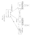
- Fig. 1 is a view illustrating how to exchange presence information in a conventional presence service.
- a user A uses a communication terminal A (node A)
- a user B uses a communication terminal B (node B)
- a presence server is available for providing control to presence services.
- the node A transmits a PUBLISH message with the presence information to the presence server.
- the presence server receives the transmitted presence information and then associates it with the user A to retain it therein.
- the node B transmits a SUBSCRIBE message directed to the node A to the presence server prior to making a call to the node A.
- the presence server transmits the presence information associated with the user A to the node B as a NOTIFY message.
- the node B receives the presence information, acknowledges the presence of the user A based on the contents thereof, and then initiates or cancels the call connection.
- the structure of presence information indicative of the presence of a person is discussed as a presence data model.
- the data elements of the presence data model are largely divided into three data elements: person, service, and device.
- the person refers to the data on the user himself/herself, for example, activity information such as being at a meeting or even emotion such as feeling sad.
- the service means data on communication services such as telephone calls or instant messages and may include, for example, the data on the specification or capability of an image or speech communication scheme.
- the device is concerned with the data on physical elements such as telephones or personal computers (PC) and may include data such as the availability for communications of whether PCs are running or the remaining level of batteries or the like.
- the presence of a person can be expressed in the combination of the aforementioned three data elements. For example, one user may be associated with a plurality of nodes when using a telephone and a PC at the same time, in the case of which the presence information of the user can be expressed by any one of these data elements or in combination with these pieces of data.
- Non-Patent Document 1 Gonzalo Camarillo, Miguel A. Garcia Martin "IMS Standard Text. " (translated by Takuya Fukada and Takuya Kashima): RIC TELECOM
- the data elements of the presence data model are not limited to the three elements mentioned above but may include status information such as person's surrounding circumstances or environments. For example, the ambient temperature of the user can be measured, so that the resulting temperature data may be reflected on the presence of the user. This is expected to contribute to providing presence information with improved reliability.
- a conventional art shown in Fig. 1 would not work, for example, when the node C is a sensor node with a temperature sensor but also a non-presence-ready terminal node.
- the non-presence-ready terminal node such as the sensor node has no consistency with the presence-ready node in terms of the level of acknowledgement of the presence of a person.
- the sensor data could not be employed as presence information as it was.
- the present invention was developed in view of the aforementioned problems. It is therefore an object of the invention is to provide a presence information provision method and system which can incorporate non-presence-ready terminal nodes such as sensor node terminals and combine a plurality of pieces of presence information from a plurality of nodes, thereby providing presence information with improved reliability.
- a presence information provision method is directed to a communication system which includes a plurality of communication terminals each associated with the presence of a specific user and a presence server for collecting or delivering presence information indicative of the presence from or to the communication terminal.
- the method includes a circumstance presence information creation step of creating circumstance presence information associated with the user in response to a change in value of sensor data transmitted from at least one sensor node terminal.
- the method further includes a circumstance presence information delivery step of delivering the circumstance presence information created in relation to the user either in place of the presence information or in combination with the presence information.
- a presence information provision system includes a presence server for collecting or delivering presence information indicative of presence of a specific user from or to a plurality of communication terminals each associated with the presence.
- the system includes a service conversion server connected to the communication terminal and the presence server for creating circumstance presence information associated with the user in response to a change in value of sensor data transmitted from at least one sensor node terminal.
- the presence server delivers the circumstance presence information created in relation to the user either in place of the presence information or in combination with the presence information.
- the presence information provision method and system according to the present invention allow for incorporating a non-presence-ready node such as a sensor node and combining a plurality of pieces of presence information from a plurality of nodes, thereby providing the presence information with improved reliability.
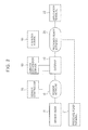
- Fig. 2 is a view illustrating an embodiment of the present invention and its overall configuration including a presence information provision system according to the present invention.
- a communication system which implements the presence information provision method according to the present invention includes a sensor network 10, a sensor node 11, a presence-ready network 20, a presence-ready terminal 21, an application terminal 22, a sensor controller 30, a gateway 40, a service conversion server 50, and a presence server 60.
- the presence information provision system according to the present invention includes at least the service conversion server 50 and the presence server 60.
- the sensor node 11 is a non-presence-ready terminal.
- the sensor node 11 is provided, for example, with a sensor such as a temperature sensor, and serves as a communication node for transmitting sensor data, which is obtained through a measurement operation of the sensor, to outside via the sensor network 10.
- the presence-ready terminal 21 is a communication terminal such as a typical PC and can transmit and receive presence information via the presence-ready network 20.
- the presence-ready network 20 may be any typical communication network so long as it can provide presence service, such as a telephone network, the Internet, or an intranet.
- Fig. 2 for purposes of illustration, only one sensor node 11 and one presence-ready terminal 21 are shown; however, the present invention is not limited thereto, but two or more sensor nodes 11 and presence-ready terminals 21 may also be employed. In this embodiment, it is assumed that a specific user is associated with the sensor node 11 and the presence-ready terminal 21.
- the sensor controller 30, which is connected to the sensor node 11 via the sensor network 10, provides for each sensor node such sensing settings as the time and cycle of transmitting sensor data to be transmitted by the sensor node.
- the service conversion server 50 may transmit control data to the sensor node 11 in order to provide sensing settings directly to the sensor node 11.
- the gateway 40 is connected between the sensor network 10 and the presence-ready network 20 and functions to transfer control data, control message, and presence information from one of the two networks to the other.
- the application terminal 22, connected to the presence-ready network 20, is an example communication node for utilizing presence information coming from the presence-ready network 20 and can be a communication terminal such as a typical PC (Personal Computer).
- the application terminal 22 itself may also be a presence-ready terminal for delivering one piece of presence information.
- the presence server 60 which is connected to the presence-ready network 20, is a server for managing presence service.
- the presence server 60 serves to receive and hold presence information from the presence-ready terminal 21, which delivers the presence information, and then send the retained presence information in response to a request from the application terminal 22 or a node that utilizes the presence information.
- the presence server 60 also functions to receive and hold presence information transmitted from the service conversion server 50 and then transmit the presence information in response to a request from the application terminal 22.
- the service conversion server 50 which is connected to the gateway 40, serves to convert a sensor data provision service from the sensor node 11 into a presence service via the gateway 40. This will be detailed later in relation to Fig. 3 .
- the sensor controller 30 and the service conversion server 50 are connected to the gateway 40; however, the present invention is not limited thereto.
- the sensor controller 30 may be connected directly to the sensor network 10 and the service conversion server 50 may also be connected directly to the presence-ready network 20, in order to implement the predetermined function.
- Fig. 3 illustrates the internal configuration of the service conversion server 50 shown in Fig. 2 .
- the service conversion server 50 is made up of at least a communication control part 51, a sensor node control part 52, a service conversion processing part 53, and a service conversion table 54.
- the communication control part 51 transmits and receives control data and control message to and from the sensor node 11, receives sensor data from the sensor node 11, and transmits presence information to the presence server 60.
- the sensor node control part 52 monitors the running status of the sensor node 11 and sets the sensor address of the sensor node 11 and the like to the service conversion table 54 as well as enables or disables the sensor node 11 in response to the running status of the sensor node 11. Furthermore, the sensor node control part 52 creates control data in accordance with the contents of the service conversion table 54, and the sensor node control part 52 then transmits the resulting data to the sensor node 11 directly or via the sensor controller 30.
- the service conversion processing part 53 converts sensor data from the sensor node 11 or a non-presence-ready terminal into presence information, thereby continually performing service conversions. For example, when the sensor node 11 is equipped with a temperature sensor and the temperature sensor provides a data value that exceeds a predetermined threshold, the service conversion processing part 53 estimates that the room temperature has been raised due to the presence of a person, thus creating presence information indicative of the presence of the person.
- the service conversion table 54 retains setting information on which the service conversion processing part 53 bases for processing its presence conversions.
- the contents of the service conversion table 54 may be either preset manually or automatically set by the sensor node control part 52 in response to an initiation message from the sensor node 11 that is a non-presence-ready terminal.
- Fig. 4 illustrates an example setting of the service conversion table 54 shown in Fig. 3 .
- the service conversion table 54 contains entries such as a sensor address, a sensing setting value, a server address, and an enable flag, the contents of each entry being set for each sensor node.
- the sensor address has a description of the network address of the sensor node 11, so that the sensor node 11 is uniquely identified in the sensor network 10.
- the sensing setting value for example, has a description of information for defining a measurement mode such as an acquisition cycle at which the sensor node 11 acquires sensor data. For instance, an acquisition cycle of 10 seconds means that the sensor node 11 transmits sensor data, to be received by the service conversion server 50, at a rate of once in 10 seconds.
- the presence definition has setting information for defining the correspondence between the sensor data value created by the sensor node and the contents of presence information.
- the definition may include a description such as a point of change in presence status, for example, the range of sensor values.
- the presence status is assumed to change at a temperature higher than 30.0°C. i.e., at a temperature data value ⁇ 30.0.
- the server address allows the presence server 60 to be provided with a network address setting and uniquely identified in the presence-ready network 20.
- the presence server 60 being made identifiable in turn makes it possible to specify the presence service to be offered.
- the network address of the presence server 60 may have not a physical device address but instead a logical address description such as a SIP-URL (Session Initiation Protocol - Uniform Resource Locator).
- the enable flag may be provided with an ON/OFF status setting indicative of whether the sensor node 11 or a non-presence-ready terminal should be enabled as a presence-ready terminal.
- the sensor node 11 with the enable flag having an ON status setting is registered (REGISTER) by the sensor node control part 52 with the presence server 60, and will function then as a presence-ready terminal onward.
- the sensor node 11 is registered with the presence server 60.
- a plurality of sensor nodes including other than the sensor node 11 may also be registered with the presence server 60 for its service. That is, a set of multiple pieces of sensor data may be employed to create presence information.
- Fig. 5 shows a procedure for the service conversion server 50 to register the sensor node 11 or a non-presence-ready terminal with the presence server 60. After such registration, provision of actual presence service (see Fig. 7 to be described later) will be started.
- the service conversion server 50 sets the sensor address, the sensing setting value, the presence definition, and the server address to the service conversion table 54 (step S11).
- the settings of the service conversion table 54 are input manually.
- the service conversion server 50 extracts one sensor address from the service conversion table 54 (step S12) to determine whether the sensor node associated with the sensor address has been activated (step S13).
- the method for extracting one sensor address from the service conversion table 54 is, for example, to extract one sensor node from top of the service conversion table 54 in sequence.
- the process determines whether the sensor node 11 has been activated. If the sensor node 11 is not active, the process turns OFF the enable flag, and after a predetermined period of time, determines again whether the sensor node is active (step S13).
- the determination of whether the node has been activated can be realized, for example, by the service conversion server 50 transmitting a confirmatory message to the sensor controller 30.
- the service conversion server 50 turns ON the enable flag for the sensor node 11 to enable the sensor node 11 (step S14).
- the process registers it with the presence server 60 by transmitting the REGISTER message thereto and transmits control data to the sensor node 11 to set its operation mode. Subsequently, the process continues processing for another sensor node.
- Fig. 6 shows a modified example procedure for the service conversion server 50 to register the sensor node 11. That is, in this modified example, the service conversion server 50 automatically creates the service conversion table 54.
- the service conversion server 50 always keeps waiting for the initiation message from a sensor node (step S21).
- the sensor node 11 automatically delivers the initiation message.
- the service conversion server 50 determines whether the initiation message has arrived (step S22). The service conversion server 50 returns repeatedly to step S21 to keep the wait status until the initiation message arrives.
- the service conversion server 50 extracts the sensor address of the sensor node 11 from the initiation message, and creates the sensing setting value, the presence definition, and the server address by associating them with the sensor address of the sensor node 11. Then, the server 50 sets these entries to the service conversion table 54 (step S23). These setting contents can be created, for example, based on the address list and the setting value lookup table that have been prepared in advance for each sensor node.
- the service conversion server 50 turns ON the enable flag for the sensor node 11 to enable the sensor node 11 (step S24).
- the process registers it with the presence server 60 by transmitting the REGISTER message thereto and transmits control data to the sensor node 11 to set its operation mode. Subsequently, the process returns to step S21 to continue processing for another sensor node.
- Fig. 7 illustrates the procedure for converting the sensor data of the sensor node 11 into presence information to inform the application terminal 22 of the resulting information.
- the service conversion server 50 enables the sensor node 11 (step S31).
- the sensor node 11 is enabled based on the procedure shown Fig. 5 or in Fig. 6 .
- the operation is initiated in response to the initiation message from the sensor node 11 to create control data to be directed to the sensor node 11.
- the service conversion server 50 registers the sensor node 11 with the presence server 60 by transmitting the REGISTER message thereto (step S32).
- control data transmitted from the service conversion server 50 are set to the sensor node 11 directly or via the sensor controller 30.
- the sensor node 11 starts to create and transmit sensor data in accordance with the contents of control data (step S33).
- the transmitted sensor data is received by the service conversion server 50.
- the service conversion server 50 converts the received sensor data into presence information in accordance with the contents of the service conversion table 54, and then transmits the presence information as the PUBLISH message to the presence server 60 (step S34). From then onward, the service conversion server 50 creates and transmits presence information in response to a change in the value of the sensor data when the sensor data has been transmitted from the enabled sensor node 11.
- the service conversion server 50 does not need to create presence information each time the sensor node 11 transmits the sensor data. For example the service conversion server 50 determines each time the sensor data is transmitted whether there is a change in the value of the sensor data, and if there is a change, transmits the presence information to the presence server 60. For example, the service conversion server 50 may create presence information and transmit it to the presence server 60 only when the value of the temperature sensor data has exceeded 30°C.
- the service conversion server 50 may monitor a sensor node in parallel to create presence information in response to the result of monitoring (step S35).
- a monitoring result may be a problem with the sensor status of the sensor node 11 or the network status of the sensor network 10. Those modes will be described later with reference to Fig. 8 .
- the presence server 60 receives presence information from the service conversion server 50 and at the same time receives presence information (PUBLISH message) from a typical presence-ready terminal 21 (step S36).
- presence information PBLISH message
- PUBSCRIBE message requests the delivery of presence information of a specific user by specifying the user.
- the presence of the user is intended to be associated with the sensor node 11 and the presence-ready terminal.
- the presence server 60 combines the presence information from the service conversion server 50 (i.e., the presence information from the sensor node 11) and the presence information from the presence-ready terminal 21 into one piece of presence information (step S38).
- the combination can be provided such that it includes only the presence information from the sensor node 11 or the combination of the presence information from the sensor node 11 and the presence information from the presence-ready terminal 21.
- various pieces of presence information may be produced for each combination of the presence status representative of one piece of presence information and the presence status indicative of the other piece of presence information.
- the presence server 60 sends the resulting presence information as a NOTIFY message to the application terminal 22 (step S39).
- the application terminal 22 carries out presence-ready processing in accordance with the contents of the NOTIFY message (step S40). For example, the terminal 22 may make a call for a call connection, or alternatively, simply indicate a change in the presence for the user to recognize it.
- Fig. 8 shows in more detail the sensor node monitoring procedure shown in Fig. 7 .
- the service conversion server 50 extracts one sensor address of those of non-presence-ready terminal nodes whose sensor node status is to be monitored (step S51). Then, the service conversion server 50 transmits a confirmatory message to check if the sensor node of the address (by way of example, the sensor node 11 in this embodiment) has been activated, thereby monitoring the sensor node 11 (step S52).
- the service conversion server 50 determines whether the sensor node 11 is working (step S53). If it is working, the service conversion server 50 continues service conversions for the sensor node 11 (step S58). For example, the sensor node 11 is determined to be working if the sensor node 11 sends back a response message to the confirmatory message within a give period of time.
- the service conversion server 50 determines whether the transmission path leading to the sensor node 11 is normal without any network failure (step S54).
- the network failure on the transmission path may be expected to include, for example, a failure in the gateway 40 or a failure of an intermediate node on the sensor network 10.
- the gateway 40 can be determined to be normal or abnormal by periodically transmitting a diagnostic message to the gateway 40.
- An intermediate node on the sensor network 10 can be determined to be normal or abnormal, for example, according to the result of response to the inquiry message directed to the sensor controller 30 or another controlled node.
- the process may determine that the transmission path leading to the sensor node 11 is normal without any network failure. In this case, the process recognizes that the sensor node 11 itself is abnormal and then creates node status presence information indicating that the sensor node is failed. On the other hand, the transmission path may be determined to be abnormal with some network failure. In this case, the service conversion server 50 recognizes that there has occurred a failure on the transmission path leading to the sensor node 11, and then creates network status presence indicating that there is a network failure. Then, the process transmits the resulting node status presence information or network status presence to the presence server 60 (step S57).
- the presence server 60 updates the presence information of the user associated with the sensor node 11 in response to the transmitted node status presence information or network status presence to prepare for a request to acquire the presence information of the user.
- the presence conversion server is provided to collect sensor data from a sensor node and create presence information from the sensor data. This allows for obtaining not only presence information such as the online status of a PC operated by a person but also such presence information that contains circumstance presence information indicative of the emotion or ambient situations of a person. It is thus possible to grasp the presence of person in greater detail or in various forms.
- presence could be recognized with improved reliability. This may be achieved by the service conversion server 50 monitoring the status of a sensor node when sensor data cannot be obtained as having been initially set, so that the status can be reflected on the presence information in the event of occurrence of a failure. On the other hand, not only presence information based on sensor data but also the presence information of a sensor node itself may be delivered, thereby allowing the user using the presence service to determine the reliability of the presence information.
- the sensor node 11 was described as a sensor node that includes a temperature sensor; however, the present invention is not limited thereto.
- a sound sensor may be alternatively employed so that at a sensor level greater than a certain value, multiple people present at the spot are considered to be talking to each other, thus creating presence information indicative of presence "being busy”.
- a cigarette smoke sensor may work allowing to create "At break (available to answering a call)," or a wash room human-sensitive sensor may act allowing to create “At break (unavailable to answering a call).”
- Other forms may be found, for example, as a kitchen gas meter being activated allowing to create "At break (unavailable to answering a call).”
- a high temperature or high humidity may lead to creating presence information as “uncomfortable,”
- the presence-ready terminal 21 has been described as a communication node associated with a presence service and a terminal that can transmit presence information to the presence server 60.
- the presence-ready terminal 21 may be provided with a function similar to that of the service conversion server 50. This may allow the terminal 21 to acquire not only the presence information created within the presence-ready terminal 21 but also the sensor data from the sensor node 11 via the sensor network 10 and the gateway 40. Thus, the terminal 21 could perform the service conversion function instead of the service conversion server 50.
Landscapes
- Engineering & Computer Science (AREA)
- Computer Networks & Wireless Communication (AREA)
- Signal Processing (AREA)
- Telephonic Communication Services (AREA)
Applications Claiming Priority (1)
| Application Number | Priority Date | Filing Date | Title |
|---|---|---|---|
| JP2009194504A JP5458744B2 (ja) | 2009-08-25 | 2009-08-25 | プレゼンス情報提供方法及びシステム |
Publications (1)
| Publication Number | Publication Date |
|---|---|
| EP2290908A1 true EP2290908A1 (en) | 2011-03-02 |
Family
ID=43064656
Family Applications (1)
| Application Number | Title | Priority Date | Filing Date |
|---|---|---|---|
| EP10162105A Withdrawn EP2290908A1 (en) | 2009-08-25 | 2010-05-06 | System and method for providing presence information |
Country Status (3)
| Country | Link |
|---|---|
| US (1) | US8171076B2 (ja) |
| EP (1) | EP2290908A1 (ja) |
| JP (1) | JP5458744B2 (ja) |
Cited By (2)
| Publication number | Priority date | Publication date | Assignee | Title |
|---|---|---|---|---|
| WO2016133659A1 (en) * | 2015-02-19 | 2016-08-25 | Vivint, Inc. | Methods and systems for automatically monitoring user activity |
| WO2016206042A1 (en) * | 2015-06-25 | 2016-12-29 | Thomson Licensing | Gateway and diagnosing method thereof |
Families Citing this family (7)
| Publication number | Priority date | Publication date | Assignee | Title |
|---|---|---|---|---|
| CN101227295B (zh) * | 2007-01-15 | 2011-02-02 | 杭州华三通信技术有限公司 | 基于同轴电缆网上的以太网收发装置及以太网传输方法 |
| KR100937872B1 (ko) * | 2007-12-17 | 2010-01-21 | 한국전자통신연구원 | 무선 센서네트워크에서 센서모듈을 위한센서노드동적관리장치 및 방법 |
| US9064243B2 (en) * | 2012-02-16 | 2015-06-23 | Blackberry Limited | System and method for communicating presence status |
| CN103368755A (zh) * | 2012-03-30 | 2013-10-23 | 富泰华工业(深圳)有限公司 | 远端服务器运行管理系统和管理方法 |
| US9401952B1 (en) | 2013-03-13 | 2016-07-26 | Shortel, Inc. | Managing presence state |
| JP6761633B2 (ja) * | 2015-12-10 | 2020-09-30 | ローム株式会社 | コントローラノード、センサネットワークシステム、およびその動作方法 |
| EP3993340A1 (en) * | 2020-11-02 | 2022-05-04 | Schneider Electric Industries SAS | Iot gateway for industrial control systems, associated devices, systems and methods |
Citations (4)
| Publication number | Priority date | Publication date | Assignee | Title |
|---|---|---|---|---|
| US20060010240A1 (en) * | 2003-10-02 | 2006-01-12 | Mei Chuah | Intelligent collaborative expression in support of socialization of devices |
| US20080240384A1 (en) * | 2007-03-29 | 2008-10-02 | Lalitha Suryanarayana | Methods and apparatus to provide presence information |
| US20080278312A1 (en) * | 2007-05-09 | 2008-11-13 | Sony Ericsson Mobile Communications Ab | Methods, electronic devices, and computer program products for generating presence information associated with a user of an electronic device based on environmental information |
| WO2009043020A2 (en) * | 2007-09-28 | 2009-04-02 | The Trustees Of Dartmouth College | System and method for injecting sensed presence into social networking applications |
Family Cites Families (22)
| Publication number | Priority date | Publication date | Assignee | Title |
|---|---|---|---|---|
| US7152045B2 (en) * | 1994-11-28 | 2006-12-19 | Indivos Corporation | Tokenless identification system for authorization of electronic transactions and electronic transmissions |
| US7937461B2 (en) * | 2000-11-09 | 2011-05-03 | Intel-Ge Care Innovations Llc | Method for controlling a daily living activity monitoring system from a remote location |
| US20080301298A1 (en) * | 2002-07-29 | 2008-12-04 | Linda Bernardi | Identifying a computing device |
| GB0218716D0 (en) * | 2002-08-12 | 2002-09-18 | Mitel Knowledge Corp | Privacy and security mechanism fo presence systems with tuple spaces |
| ES2329683T3 (es) * | 2004-02-20 | 2009-11-30 | Fico Mirrors, Sa | Sistema de control de funcionamiento de dispositivos detectores de presencia y metodo para su realizacion. |
| US7426538B2 (en) * | 2004-07-13 | 2008-09-16 | International Business Machines Corporation | Dynamic media content for collaborators with VOIP support for client communications |
| US7921369B2 (en) * | 2004-12-30 | 2011-04-05 | Aol Inc. | Mood-based organization and display of instant messenger buddy lists |
| US20070239755A1 (en) * | 2005-01-10 | 2007-10-11 | Instant Information Inc. | Methods and systems for messaging in a collaboration system |
| JP2006211236A (ja) * | 2005-01-27 | 2006-08-10 | Mitsubishi Electric Corp | プレゼンス流通システム |
| CA2540404A1 (en) * | 2005-03-21 | 2006-09-21 | Magna International Inc. | Image-based vehicle occupant classification system |
| US7318001B2 (en) * | 2005-05-03 | 2008-01-08 | Cnv Technologies, Llc | Method and apparatus for collecting data for detecting and locating disturbances |
| CN101278568B (zh) * | 2005-08-16 | 2010-12-15 | 尼尔森(美国)有限公司 | 显示装置开/关检测方法和设备 |
| JP4420955B2 (ja) * | 2005-09-29 | 2010-02-24 | 富士通株式会社 | プレゼンス通信システム及び方法 |
| CN101460946B (zh) * | 2006-04-21 | 2013-06-12 | 意大利电信股份公司 | 用于提供呈现信息的方法和系统 |
| JP5037072B2 (ja) * | 2006-08-31 | 2012-09-26 | ガイアホールディングス株式会社 | プレゼンスサービス端末及びプレゼンスサービスシステム |
| ATE456355T1 (de) * | 2006-11-14 | 2010-02-15 | Beldico Integrated Solutions S | Vorrichtung zur automatischen bewegungsdetektion von objekten |
| US8224359B2 (en) * | 2006-12-22 | 2012-07-17 | Yahoo! Inc. | Provisioning my status information to others in my social network |
| US20080242231A1 (en) * | 2007-03-29 | 2008-10-02 | Sony Ericsson Mobile Communications Ab | Updating Presence Based on Detecting User Activity |
| ATE466442T1 (de) * | 2007-05-24 | 2010-05-15 | France Telecom | System und verfahren zur verarbeitung von informationen über den präsenzzustand mit verbesserter zuverlässigkeit |
| JP2010041482A (ja) * | 2008-08-06 | 2010-02-18 | Nippon Telegr & Teleph Corp <Ntt> | プレゼンス情報生成システム、コンピュータプログラム、およびプレゼンス情報生成方法 |
| US8473733B2 (en) * | 2008-10-14 | 2013-06-25 | Research In Motion Limited | Method for managing opaque presence indications within a presence access layer |
| US8489112B2 (en) * | 2009-07-29 | 2013-07-16 | Shopkick, Inc. | Method and system for location-triggered rewards |
-
2009
- 2009-08-25 JP JP2009194504A patent/JP5458744B2/ja not_active Expired - Fee Related
-
2010
- 2010-05-06 EP EP10162105A patent/EP2290908A1/en not_active Withdrawn
- 2010-05-14 US US12/662,995 patent/US8171076B2/en not_active Expired - Fee Related
Patent Citations (4)
| Publication number | Priority date | Publication date | Assignee | Title |
|---|---|---|---|---|
| US20060010240A1 (en) * | 2003-10-02 | 2006-01-12 | Mei Chuah | Intelligent collaborative expression in support of socialization of devices |
| US20080240384A1 (en) * | 2007-03-29 | 2008-10-02 | Lalitha Suryanarayana | Methods and apparatus to provide presence information |
| US20080278312A1 (en) * | 2007-05-09 | 2008-11-13 | Sony Ericsson Mobile Communications Ab | Methods, electronic devices, and computer program products for generating presence information associated with a user of an electronic device based on environmental information |
| WO2009043020A2 (en) * | 2007-09-28 | 2009-04-02 | The Trustees Of Dartmouth College | System and method for injecting sensed presence into social networking applications |
Non-Patent Citations (1)
| Title |
|---|
| BROK J ET AL: "ENABLING NEW SERVICES BY EXPLOITING PRESENCE AND CONTEXT INFORMATION IN IMS", BELL LABS TECHNICAL JOURNAL, WILEY, CA, US, vol. 4, no. 10, 1 January 2006 (2006-01-01), pages 83 - 100, XP001239288, ISSN: 1089-7089, DOI: 10.1002/BLTJ.20126 * |
Cited By (4)
| Publication number | Priority date | Publication date | Assignee | Title |
|---|---|---|---|---|
| WO2016133659A1 (en) * | 2015-02-19 | 2016-08-25 | Vivint, Inc. | Methods and systems for automatically monitoring user activity |
| US9942056B2 (en) | 2015-02-19 | 2018-04-10 | Vivint, Inc. | Methods and systems for automatically monitoring user activity |
| US10419235B2 (en) | 2015-02-19 | 2019-09-17 | Vivint, Inc. | Methods and systems for automatically monitoring user activity |
| WO2016206042A1 (en) * | 2015-06-25 | 2016-12-29 | Thomson Licensing | Gateway and diagnosing method thereof |
Also Published As
| Publication number | Publication date |
|---|---|
| US8171076B2 (en) | 2012-05-01 |
| JP2011049668A (ja) | 2011-03-10 |
| JP5458744B2 (ja) | 2014-04-02 |
| US20110055319A1 (en) | 2011-03-03 |
Similar Documents
| Publication | Publication Date | Title |
|---|---|---|
| US8171076B2 (en) | System and method for providing presence information | |
| US20220264274A1 (en) | Method and system for emergency call management | |
| US9954995B2 (en) | End to end design of personal emergency service utilizing M2M cellular, XMPP/XML technologies on mobile help button | |
| US8401154B2 (en) | Emergency text communications | |
| JP4740328B2 (ja) | シンクサーバーを用いたメッセンジャー通知システム及びその方法 | |
| AU2004202814B2 (en) | Communication Exchanging System Capable of Changing Forwarding Destination According to Notification of Presence Change of User | |
| CN103037319B (zh) | 通信转移方法、移动终端及服务器 | |
| US8098810B2 (en) | Intelligent presence management in a communication routing system | |
| CN101521677B (zh) | 信息分发系统 | |
| JP2009541902A (ja) | プレゼンス・サーバでのユーザ状態の遠隔更新 | |
| US20100246569A1 (en) | Temporary connection number management system, terminal, temporary connection number management method, and temporary connection number management program | |
| JP4633842B2 (ja) | メッセンジャーを用いた通知システム及び方法 | |
| JP2006197126A (ja) | プレゼンスサーバ、移動機、プレゼンス情報管理システムおよびプレゼンス情報管理方法 | |
| US20110051910A1 (en) | Method and apparatus for Forwarding Voicemail | |
| JP4240218B2 (ja) | 監視システム、監視通報装置および監視システムにおける通信方法 | |
| KR101283808B1 (ko) | 메신저와 이동통신 단말기간의 통신방법 및 그 시스템 | |
| JP4002545B2 (ja) | 音声通信システム及び音声通信方法 | |
| JP2012257086A (ja) | ゲートウエイ装置 | |
| JP5037072B2 (ja) | プレゼンスサービス端末及びプレゼンスサービスシステム | |
| KR101686947B1 (ko) | 고객관리 서비스 제공 방법 | |
| US8588212B2 (en) | IP telephone system, network device, communication method in disaster situations used therefor and IP telephone terminal | |
| JP6327815B2 (ja) | 緊急通報システム、緊急通報装置、サーバおよび緊急通報方法 | |
| JP2006050004A (ja) | 電子メール着信通知装置及び電子メール着信通知方法 | |
| JP2008193236A (ja) | 遠隔監視装置及びこれを用いた遠隔監視システム | |
| KR20070011865A (ko) | 네트워크 상태 표시기능을 갖는 이동통신 단말기, 이를이용한 인스턴트 메시징 시스템 |
Legal Events
| Date | Code | Title | Description |
|---|---|---|---|
| PUAI | Public reference made under article 153(3) epc to a published international application that has entered the european phase |
Free format text: ORIGINAL CODE: 0009012 |
|
| AK | Designated contracting states |
Kind code of ref document: A1 Designated state(s): AL AT BE BG CH CY CZ DE DK EE ES FI FR GB GR HR HU IE IS IT LI LT LU LV MC MK MT NL NO PL PT RO SE SI SK SM TR |
|
| AX | Request for extension of the european patent |
Extension state: BA ME RS |
|
| 17P | Request for examination filed |
Effective date: 20110902 |
|
| 17Q | First examination report despatched |
Effective date: 20131018 |
|
| STAA | Information on the status of an ep patent application or granted ep patent |
Free format text: STATUS: THE APPLICATION IS DEEMED TO BE WITHDRAWN |
|
| 18D | Application deemed to be withdrawn |
Effective date: 20131203 |