EP2290782A2 - Non-contact electric power feeding apparatus, non-contact electric power receiving apparatus, non-contact electric power feeding method, non-contact electric power receiving method and non-contact electric power feeding system - Google Patents
Non-contact electric power feeding apparatus, non-contact electric power receiving apparatus, non-contact electric power feeding method, non-contact electric power receiving method and non-contact electric power feeding system Download PDFInfo
- Publication number
- EP2290782A2 EP2290782A2 EP10007328A EP10007328A EP2290782A2 EP 2290782 A2 EP2290782 A2 EP 2290782A2 EP 10007328 A EP10007328 A EP 10007328A EP 10007328 A EP10007328 A EP 10007328A EP 2290782 A2 EP2290782 A2 EP 2290782A2
- Authority
- EP
- European Patent Office
- Prior art keywords
- electric power
- resonance
- power feeding
- noncontact
- resonance element
- Prior art date
- Legal status (The legal status is an assumption and is not a legal conclusion. Google has not performed a legal analysis and makes no representation as to the accuracy of the status listed.)
- Granted
Links
- 238000000034 method Methods 0.000 title claims description 25
- 230000008878 coupling Effects 0.000 claims abstract description 92
- 238000010168 coupling process Methods 0.000 claims abstract description 92
- 238000005859 coupling reaction Methods 0.000 claims abstract description 92
- 239000003990 capacitor Substances 0.000 claims description 21
- 230000005540 biological transmission Effects 0.000 description 55
- 230000005284 excitation Effects 0.000 description 33
- ORQBXQOJMQIAOY-UHFFFAOYSA-N nobelium Chemical compound [No] ORQBXQOJMQIAOY-UHFFFAOYSA-N 0.000 description 22
- 230000014509 gene expression Effects 0.000 description 15
- 238000010586 diagram Methods 0.000 description 12
- 230000005674 electromagnetic induction Effects 0.000 description 10
- 238000006243 chemical reaction Methods 0.000 description 5
- 230000005684 electric field Effects 0.000 description 5
- CNQCVBJFEGMYDW-UHFFFAOYSA-N lawrencium atom Chemical compound [Lr] CNQCVBJFEGMYDW-UHFFFAOYSA-N 0.000 description 4
- 230000009467 reduction Effects 0.000 description 4
- 238000001514 detection method Methods 0.000 description 3
- 230000006866 deterioration Effects 0.000 description 2
- 238000012546 transfer Methods 0.000 description 2
- 230000004075 alteration Effects 0.000 description 1
- 230000008901 benefit Effects 0.000 description 1
- 230000008859 change Effects 0.000 description 1
- 238000004891 communication Methods 0.000 description 1
- 238000013461 design Methods 0.000 description 1
- 230000000694 effects Effects 0.000 description 1
- 230000005611 electricity Effects 0.000 description 1
- 230000004907 flux Effects 0.000 description 1
- 238000012986 modification Methods 0.000 description 1
- 230000004048 modification Effects 0.000 description 1
Images


Classifications
-
- H—ELECTRICITY
- H02—GENERATION; CONVERSION OR DISTRIBUTION OF ELECTRIC POWER
- H02J—CIRCUIT ARRANGEMENTS OR SYSTEMS FOR SUPPLYING OR DISTRIBUTING ELECTRIC POWER; SYSTEMS FOR STORING ELECTRIC ENERGY
- H02J50/00—Circuit arrangements or systems for wireless supply or distribution of electric power
- H02J50/10—Circuit arrangements or systems for wireless supply or distribution of electric power using inductive coupling
- H02J50/12—Circuit arrangements or systems for wireless supply or distribution of electric power using inductive coupling of the resonant type
Definitions
- the present invention relates to noncontact electric power feeding apparatus and method for feeding an electric power by using a resonance such as a magnetic field resonance or an electric field resonance, noncontact electric power receiving apparatus and method for receiving the electric power by using the resonance such as the magnetic field resonance or the electric field resonance, and a noncontact electric power feeding system for feeding the electric power by using the resonance such as the magnetic field resonance or the electric field resonance.
- An electromagnetic induction system and a magnetic field resonance system are each known as a technique for enabling an electric energy to be transmitted in a noncontact style. Also, the electromagnetic induction system and the magnetic field resonance system are different in various respects from each other. In recent years, the energy transmission using the magnetic field resonance system attracts attention.
- FIG. 8 is a conceptual diagram, partly in circuit, showing a basic configuration of a noncontact electric power feeding system using the magnetic field resonance system.
- the noncontact electric power feeding system using magnetic field resonance system is composed of an electric power feeding side (electric power feeding apparatus) 100, and an electric power receiving side (electric power receiving apparatus) 200.
- the electric power feeding side 100 includes an A.C. power source 101 and a resonance element 102.
- the A.C. power source 101 generates an A.C. electric power (A.C. current) having the same self-resonance frequency as that of the resonance element 102 and supplies the A.C. electric power thus generated to the resonance element 102.
- the electric power receiving side 200 is composed of a resonance element 201 and a load circuit 202.
- the resonance element 101 of the electric power feeding side 100 and the resonance element 201 of the electric power receiving side 200 are identical in self-resonance frequency to each other, and are coupled to each other through magnetic field coupling.
- the A.C. electric power generated by the A.C. power source 102 of the electric power feeding side 100 is supplied to the resonance element 102, thereby generating the magnetic field in the resonance element 102. Also, the magnetic field coupling is caused between the resonance element 102 of the electric power feeding side 100, and the resonance element 201 of the electric power receiving side 200 to induce the A.C. electric power in the resonance element 201 of the electric power receiving side 200. The A.C. electric power thus induced is supplied to the load circuit 202.
- an unmodulated sine wave having a central frequency f 0 is used as the A.C. power. Since this unmodulated sine wave is unmodulated one, an occupied frequency bandwidth is narrow (ideally 0 (zero) Hz).
- a frequency band necessary for the resonance coil through which the unmodulated sine wave is transmitted has to be as narrow as about several hertz.
- a Q value is large.
- the Q value represents the sharpness of the peak of the resonance in the resonance circuit, and thus when the peak of the resonance becomes sharp, it is possible to increase the transmission efficiency of the A.C. electric power.
- the Q value of the resonance element 102 is reduced due to the influence of circuit impedance.
- the resonance element 201 is directly connected to the A.C. load circuit 202 on the electric power receiving side 200 as well, the Q value of the resonance element 201 is reduced due to the influence of circuit impedance.
- FIG. 9 is a block diagram showing an example of a configuration of a noncontact electric power feeding system, using a magnetic field resonance system, which is configured in order to prevent both the reflection of the electric power, and the reduction of the Q value by providing excitation elements in both the electric power feeding side 100 and the electric power receiving side 200, respectively.
- the electric power feeding side 100 has a configuration such that an excitation element 103 is provided between the A.C. power source 101 and the resonance element 102.
- the electric power receiving side 200 has a configuration such that an excitation element 203 and a rectifying circuit 204 are provided between the resonance element 201 and the load circuit 202.
- the electric power feeding side 100 for example, is realized in the form of a charging apparatus or the like.
- the electric power receiving side 200 for example, is realized in the form of a mobile electronic apparatus such as a mobile-phone unit.
- the inside of the electric power feeding side 100 is configured in such a way that the excitation element 103 is connected to the A.C. power source 101, and the excitation element 103 and the resonance element 102 are strongly coupled to each other through the electromagnetic induction.
- the inside of the electric power receiving apparatus 200 is configured in such a way that the resonance element 201 and the excitation element 203 are strongly coupled to each other through the electromagnetic induction, the excitation element 203 is connected to the rectifying circuit 204, and the rectifying circuit 204 and the load circuit 202 are connected to each other.
- the resonance element 102 of the electric power feeding side 100, and the resonance element 201 of the electric power receiving side 200 show a magnetic field resonance relationship. As a result, a coupling amount becomes maximum, and a loss becomes minimum.
- an A.C. electric power (A.C. current) having a predetermined frequency is supplied from the A.C. power source 101 to the excitation element 103, which results in that an A.C. electric power is induced in the resonance element 102 through the electromagnetic induction.
- a frequency of the A.C. electric power generated in the A.C. power source 101 is set as being identical to each of a self-resonance frequency of the resonance element 102 of the electric power supply source, and a self-resonance frequency of the resonance element 201 of the electric power supply destination.
- the resonance element 102 of the electric power feeding side 100, and the resonance element 201 of the electric power receiving side 200 are disposed so as to show the magnetic field resonance relationship.
- the A.C. electric power is supplied from the resonance element 102 to the resonance element 201 at a resonance frequency in a noncontact style.
- the A.C. electric power supplied from the resonance element 102 of the electric power feeding side 100 is received by the resonance element 201.
- the A.C. electric power from the resonance element 201 is supplied to the rectifying circuit 204 via the excitation element 203 through the electromagnetic induction, and is then converted into a D.C. electric power (D.C. current) in the rectifying circuit 204 to be supplied to each of the various kinds of load circuits 202.
- D.C. electric power D.C. current
- the D.C. electric power is supplied from the electric power feeding side 100 to the electric power receiving side 200 in the noncontact style. It is noted that the D.C. electric power outputted from the rectifying circuit 204, for example, is supplied to a charging circuit as the load circuit 202 to which a battery is connected, thereby being used to charge the battery with the electricity.
- the noncontact electric power feeding system concerned has a relationship, as shown in FIG. 10 , between the frequency of the A.C. power source and the coupling amount.
- the coupling amount does not become large.
- the coupling amount becomes maximum only at a specific frequency at which a magnetic field resonance phenomenon is caused. That is to say, the magnetic field resonance allows the frequency property of the coupling amount to show a frequency selectivity property.
- the noncontact electric power feeding system concerned has a relationship, as shown in FIG. 11 , between a distance between the resonance elements 102 and 201, and the coupling amount. As can be seen from FIG. 12 , the coupling amount is reduced as the distance between the resonance elements 102 and 201 becomes longer.
- the coupling amount does not become large just because the distance between the resonance elements 102 and 201 is short.
- the distance at which the coupling amount becomes maximum exists at a certain resonance frequency.
- the noncontact electric power feeding system has a relationship, as shown in FIG. 12 , between the resonance frequency and the inter-resonance element distance at which the maximum coupling amount is obtained. That is to say, it is understood from FIG. 12 that when the resonance frequency is low, the resonance element interval is wide. In addition, it is also understood from FIG. 12 that when the resonance frequency is high, the maximum coupling amount can be obtained by narrowing the resonance element interval.
- the electric power feeding side and the electric power receiving side need to have a magnetic flux in common.
- the electric power feeding source and the electric power feeding destination need to be disposed close proximity to each other, and thus the axis alignment for the coupling between the electric power feeding source and the electric power feeding destination becomes also important.
- the noncontact electric power feeding system using the magnetic field resonance phenomenon has an advantage that from the principles called the magnetic field resonance phenomenon, the electric power can be transmitted at a longer distance than that in the case of the noncontact electric power feeding system using the electromagnetic induction system, and even when the axis alignment is slightly poor, the electric power transmission efficiency is not reduced so much.
- US Patent Application Publication No. 2007/0222542 discloses a technique about an electric power transmission system using the magnetic field resonance system as described above.
- the reason for this is because when the distance between the resonance element 102 of the electric power feeding side 100, and the resonance element 201 of the electric power receiving side 200 is too short to provide the tight coupling state, the resonance frequency is separated into two parts to provide double-humped resonance characteristics, and thus the electric power transmission efficiency at the central frequency becomes worse.
- the present invention has been made in order to solve the problems described above, and it is therefore desirable to provide noncontact electric power feeding apparatus and method, noncontact electric power receiving apparatus and method, and a noncontact electric power feeding system in each of which even in the case where a distance between an electric power feeding side and an electric power receiving side becomes short to provide a tight coupling state when an electric power is fed or received in a noncontact style by using a resonance system, the electric power transmission efficiency can be highly maintained.
- a noncontact electric power feeding apparatus including: a resonance element for supplying an A.C. electric power in a noncontact style in accordance with a resonance; an A.C. power source portion configured to generate an A.C. electric power to be supplied to the resonance element; and an impedance adjusting section provided between the A.C. power source portion and the resonance element for variably controlling an impedance in accordance with a coupling coefficient between the noncontact electric power feeding apparatus and an electric power feeding destination of the A.C. electric power.
- the A.C. electric power from the A.C. power source portion is supplied to the resonance element, whereby the magnetic field is generated in the resonance element, and the A.C. electric power is supplied to an electric power receiving apparatus in accordance with the resonance.
- the impedance is adjusted so as to be suitable in accordance with the coupling coefficient between the noncontact electric power feeding apparatus and the electric power feeding destination of the A.C. electric power by the impedance adjusting section provided between the A.C. power source and the resonance element.
- the distance between the noncontact electric power feeding apparatus concerned and a noncontact electric power receiving apparatus as the electric power feeding destination of the A.C. electric power is changed, whereby even when the coupling coefficient between the noncontact electric power feeding apparatus and the noncontact electric power receiving apparatus as the electric power feeding destination of the A.C. electric power is changed, the impedance of the resonance element is suitably changed, thereby allowing the noncontact electric power feeding to be carried out at a high efficiency.
- the impedance adjusting means includes: an adjusting section composed of one of or both of a variable inductor and a variable capacitor; a detecting section configured to detect a magnitude of a reflected electric power which is changed in accordance with the coupling coefficient; and a control section configured to control the adjusting section in accordance with the magnitude of the reflected electric power detected by the detecting section.
- the magnitude of the reflected electric power which is changed in accordance with the coupling coefficient is detected by the detecting section, and the control section is informed of the detection results. Also, the adjusting section composed of one of or both of the variable inductor and the variable capacitor is controlled by the control section, and thus the impedance of the resonance element is properly controlled on a steady basis.
- the impedance of the resonance element is suitably changed, thereby allowing the noncontact electric power feeding to be carried out at the high efficiency.
- a noncontact electric power receiving apparatus including: a resonance element for receiving an A.C. electric power in a noncontact style in accordance with a resonance from a resonance element of an electric power feeding source; a rectifying circuit for creating a D.C. electric power from the A.C. electric power received through the resonance element to output the D.C. electric power thus created; and an impedance adjusting section provided between the resonance element and the rectifying circuit for variably controlling an impedance in accordance with a magnitude of a coupling coefficient between the noncontact electric power receiving apparatus and the electric power feeding source of the A.C. electric power.
- a noncontact electric power feeding method including the step of: variably controlling an impedance in accordance with a coupling coefficient between an A.C. power source portion for generating an A.C. electric power, and an electric power feeding destination of the A.C. electric power between the A.C. power source portion and a resonance element for supplying the A.C. electric power from the A.C. power source portion to another electronic apparatus in a noncontact style.
- a noncontact electric power receiving method including the step of: variably controlling an impedance in accordance with a magnitude of a coupling coefficient between an electric power feeding source of an A.C. electric power and an electric power feeding destination of the A.C. electric power between a resonance element for receiving the A.C. electric power in a noncontact style in accordance with a resonance from a resonance element of the electric power feeding source, and a rectifying circuit for creating a D.C. electric power from the A.C. electric power received through the resonance element to output the D.C. electric power thus created.
- a noncontact electric power feeding system including: a noncontact electric power feeding apparatus including: a resonance element for supplying an A.C. electric power in a noncontact style in accordance with a resonance; an A.C. power source portion configured to generate an A.C. electric power to be supplied to the resonance element; and an impedance adjusting section provided between the A.C. power source portion and the resonance element for variably controlling an impedance in accordance with a coupling coefficient between the noncontact electric power feeding apparatus and an electric power feeding destination of the A.C. electric power; and a noncontact electric power receiving apparatus including: a resonance element for receiving the A.C.
- the impedance is properly matched, thereby making it possible to highly maintain the transmission efficiency.
- noncontact electric power feeding apparatus and method noncontact electric power receiving apparatus and method
- a noncontact electric power feeding system according to embodiments of the present invention will be described in detail with reference to the accompanying drawings.
- resonance systems such as the magnetic field resonance system, the electric field resonance system, and the electromagnetic resonance system, hereinafter, a description will be given by exemplifying the case where the magnetic field resonance system is used.
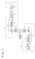
- FIG. 1 is a block diagram, partly in circuit, showing a configuration of the noncontact electric power feeding system using the magnetic field resonance system according to an embodiment of the present invention.
- the noncontact electric power feeding system using the magnetic field resonance system according to the embodiment of the present invention is composed of an electric power feeding side (electric power feeding source) 1, and an electric power receiving side (electric power feeding destination) 2.
- the electric power feeding side 1 feeds the electric power to another electronic apparatus in a noncontact style by using the magnetic field resonance system, and realizes a function as a noncontact electric power feeding apparatus.
- the electric power feeding side 1 for example, is realized in the form of an electronic apparatus such as a charging apparatus (cradle).
- the electric power receiving side 2 receives the electric power from the electric power feeding side 1 in a noncontact style in the embodiment, and uses the electric power for driving of an auto-load circuit, and realizes a function of a noncontact electric power receiving apparatus.
- the electric power receiving side 2 is realized in the form of any, of various kinds of electronic apparatuses, which is required to receive the electric power from the outside in the noncontact style and which is typified by a mobile-phone unit.
- the electric power feeding side 1 includes an A.C. power source 11, an automatic matching box 12, an excitation element 13, and a resonance element 14 for the electric power feeding.
- each of the excitation element 13, and the resonance element 14 for the electric power feeding is constructed in the form of an air core coil.
- a function as an impedance converter 15 is realized by the automatic matching box 12 and the excitation element 13.
- the excitation element 13 obtains the impedance matching between the A.C. power source 11 and the resonance element 14 for the electric power feeding, thereby preventing reflection of the electric power.
- the excitation element 13 realizes a function of highly maintaining a Q value of the resonance element 14 by fixedly setting the impedance of the resonance element 14 for the electric power feeding as a suitable value.
- a conversion rate of the impedance using the excitation element 13 is fixed.
- the impedance needs to be controlled so as to match the impedance which is changed in accordance with a coupling coefficient, k, which is changed depending on the transmission distance of the electric power.
- the automatic matching box 12 realizes a function of variably adjusting an impedance of a resonance circuit having the resonance element 14 for the electric power feeding in accordance with the coupling coefficient, k, which is changed depending on the transmission distance of the electric power. In such a manner, the automatic matching box 12 has the function of variably controlling the impedance conversion rate.
- the electric power receiving side 2 includes a resonance element 21 for electric power reception, an excitation element 22, an automatic matching box 23, a rectifying circuit 24, and a load circuit 25.
- each of the resonance element 21 for electric power reception and the excitation element 22 is constructed in the form of an air core coil.
- a function as an impedance converter 26 is realized by the excitation element 22 and the automatic matching box 23.
- the excitation element 22 obtains the impedance matching between the resonance element 21 for electric power reception and the rectifying circuit 23, thereby preventing the reflection of the electric power.
- the excitation element 22 realizes a function of highly maintaining the Q value of the resonance element 21 for electric power reception by fixedly maintaining the impedance of the resonance element 21.
- a conversion rate of the impedance using the excitation element 22 is fixed. For this reason, in the electric power receiving side 2 as well, the impedance needs to be controlled so as to match the impedance which is changed in accordance with the coupling coefficient, k, which is changed depending on the transmission distance of the electric power.
- the automatic matching box 23 realizes a function of variably adjusting an impedance of a resonance circuit having the resonance element 21 for the electric power reception in accordance with the coupling coefficient, k, which is changed depending on the transmission distance of the electric power. In such a manner, the automatic matching box 23 has the function of variably controlling the impedance conversion rate.
- the resonance element 14 of the electric power feeding side 1, and the resonance element 21 of the electric power receiving side 2 are identical in self-resonance frequency to each other, and are coupled to each other through the magnetic field coupling. Also, an input/output impedance between the resonance element 14 and the resonance element 21 depends on the coupling coefficient k between the resonance elements and the Q value of the resonance element. Thus, there is shown a relationship that the input impedance becomes small as both the coupling coefficient k and the Q value are larger.
- the A.C. power source 11 of the electric power feeding side 1 generates an A.C. electric power (A.C. current) having the same frequency or approximately the same frequency as the self-resonance frequency of the resonance element 14 of the electric power feeding side 1, and supplies the A.C. electric power thus generated to the excitation element 13 through the automatic matching box 12.
- A.C. power source 11 of the electric power feeding side 1 for example, includes a Colpitts oscillating circuit, a Hartley oscillating circuit or the like.
- the excitation element 13 of the electric power feeding side 1 is an element which is excited by the A.C. electric power supplied thereto from the A.C. power source 11, thereby supplying the A.C. electric power therefrom to the resonance element 14 for the electric power feeding.
- the excitation element 13 which receives the A.C. electric power supplied thereto from the A.C. power source 11, and the resonance element 14 for the electric power feeding are strongly coupled to each other through the electromagnetic induction. To this end, the A.C. electric power from the A.C. power source 11 is supplied to the resonance element 14 for the electric power feeding through the excitation element 13.
- the resonance element 14 for the electric power feeding generates the magnetic field in accordance with the A.C. electric power supplied thereto from the excitation element 13.
- the resonance element 14 for the electric power feeding includes an inductor L and a capacitor C. The strength of the magnetic field of the resonance element 14 for the electric power feeding becomes highest at a resonance frequency.
- the resonance frequency f 01 of the resonance element 14 for the electric power feeding depends on the inductance L 1 and the capacitance C 1 each of which the resonance element 14 for the electric power feeding has.
- a line capacitor of the resonance element 14 for the electric power feeding plays a part of the capacitor.
- the resonance element 14 for the electric power feeding generates the magnetic field in an axial direction of the coil.
- the resonance element 21 for the electric power reception of the electric power receiving side 2 is an element which receives the A.C. electric power supplied thereto from the electric power feeding side 1 in accordance with the magnetic field coupling based on the magnetic field resonance.
- the resonance element 21 for the electric power reception has the same resonance frequency or approximately the same resonance frequency as that of the resonance element 14 for the electric power feeding of the electric power feeding side 1.
- the resonance element 21 for the electric power reception of the electric power receiving side 2 is constructed in the form of the air core coil, a line capacitor plays a part of a capacitor. Also, as shown in FIG. 1 , the resonance element 21 for the electric power reception of the electric power receiving side 2 is coupled to the resonance element 14 for the electric power feeding of the electric power feeding side 1 through the magnetic field resonance.
- the A.C. electric power is supplied from the resonance element 14 for the electric power feeding of the electric power feeding side 1 to the resonance element 21 for the electric power reception of the electric power receiving side 2 at the resonance frequency in the noncontact style through the magnetic field resonance.
- the resonance element 21 for the electric power reception and the excitation element 22 are coupled to each other through the electromagnetic induction.
- the A.C. electric power is supplied from the resonance element 21 for the electric power reception to the rectifying circuit 24 through the excitation element 22 and the automatic matching box 23.
- the rectifying circuit 24 creates a D.C. electric power which will be supplied to the load circuit 25 in a subsequent stage from the A.C. electric power supplied thereto through the excitation element 22 and the automatic matching box 23, and then supplies the D.C. electric power thus created to the load circuit 25.
- the load circuit 25, for example, is any of various kinds of circuit portions such as a charging circuit having a battery.
- the electric power can be fed from the electric power feeding side 1 to the electric power receiving side 2 in the noncontact style.
- the Q value is highly maintained by suitably holding the impedance of the resonance circuit having the resonance element 14 for the electric power feeding, and the transmission efficiency of the electric power is held at the high efficiency.
- the Q value is highly maintained by suitably holding the impedance of the resonance circuit having the resonance element 21 for the electric power reception, and the transmission efficiency of the electric power is held at the high efficiency.
- the resonance frequency is separated into two parts to provide the double-humped resonance characteristics. As a result, the transmission efficiency at the resonance frequency becomes worse.
- the automatic matching box 12 can adjust adaptively the impedance in accordance with the coupling coefficient k which is changed depending on the transmission distance.
- the automatic matching box 23 can adjust adaptively the impedance in accordance with the coupling coefficient k which is changed depending on the transmission distance.
- the resonance element 14 for the electric power feeding of the electric power feeding side 1, and the resonance element 21 for the electric power reception of the electric power receiving side 2 are identical in self-resonance frequency to each other, and are coupled to each other through the magnetic field coupling. Also, the transmission efficiency between the resonance element 14 for the electric power feeding and the resonance element 21 for the electric power reception depends on both the coupling coefficient k between the resonance element 14 for the electric power feeding and the resonance element 21 for the electric power reception, and the Q values of the resonance element 14 for the electric power feeding and the resonance element 21 for the electric power reception. Thus, the transmission efficiency of the electric power becomes high as both the coupling coefficient k and the Q value are larger.
- the coupling coefficient k depends on the distance between the resonance elements, and each of the sizes of the resonance elements.
- the coupling becomes strong and the high efficiency is obtained as each of the sizes of the resonance elements is larger and the distance between the resonance elements is shorter.
- the coupling coefficient k is changed in accordance with the distance between the resonance elements.
- the impedance of the resonance circuit having the resonance element 14 for the electric power feeding can be adjusted in accordance with the coupling coefficient k between the electric power feeding side 1 and the electric power receiving side 2.
- the impedance of the resonance circuit having the resonance element 21 for the electric power reception can be adjusted in accordance with the coupling coefficient k between the electric power feeding side 1 and the electric power receiving side 2.
- the impedance of the resonance circuit having the resonance element 14 for the electric power feeding of the electric power feeding side 1 can be both adjusted in accordance with the coupling coefficient k between the electric power feeding side 1 and the electric power receiving side 2.
- FIG. 2 is an equivalent circuit diagram of the noncontact electric power feeding system having the basic configuration in which the electric power feeding side 1 is composed of the A.C. power source 11 and the resonance element 14 for the electric power feeding, and the electric power receiving side 2 is composed of the resonance element 21 for the electric power reception, and the load circuit 25 similarly to the case of the noncontact electric power feeding system using the magnetic field resonance system shown in FIG. 8 .
- the A.C. power source 11 of the electric power feeding side 1 can be equivalently expressed in the form of an A.C. power source having an impedance R s .
- the resonance element 14 for the electric power feeding of the electric power feeding side 1 can be equivalently expressed in the form of a resonance circuit having an inductor L 1 , a capacitor C 1 , and a resistor R 1 .
- the resonance element 21 of the electric power receiving side 2 can be equivalently expressed in the form of a resonance circuit having an inductor L 2 , a capacitor C 2 , and a resistor R 2 .
- the load circuit 25 of the electric power receiving side 2 can be equivalently expressed in the form of a load having an impedance R L .
- the resonance frequency f 01 of the resonance element 14 for the electric power feeding of the electric power feeding side 1 can be expressed by Expression (1) described above.
- the resonance frequency f 02 of the resonance element 21 for the electric power reception of the electric power reception side 2 can be expressed by Expression (2) described above.
- the coupling coefficient between the resonance element 14 for the electric power feeding of the electric power feeding side 1, and the resonance element 21 for the electric power reception of the electric power reception side 2 is designated by reference symbol k.
- a Q value of the circuit composed of the resonance element (resonance circuit) 14 and the resonance element (resonance circuit) 21 is designated by reference symbol Q.
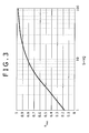
- a multiplication value (k ⁇ Q) of the coupling coefficient k and the Q value is expressed by reference symbol S.
- FIG. 4 shows transmission characteristics in the case where when this state is held, each of the power source impedance R S and the load impedance R L is fixed to 3,000 (Q), and the coupling coefficient, k, is changed to 0.01, 0.04, 0.07, and 0.21 in order.
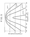
- FIG. 5 shows the transmission characteristics of the electric power when in order to cope with such a situation, the coupling coefficient k is changed to 0.01, 0.04, 0.07, and 0.1 in order in the manner as described above, and each of the power source impedance R S and the load impedance R L is made variable in accordance with Expression (7).
- each of the power source impedance R S and the load impedance R L is fixed.
- the electric power feeding side 1 is provided with the automatic matching box 12 for the impedance adjustment and the electric power receiving side 2 is provided with the automatic matching box 23 for the impedance adjustment.
- the Q value of the resonance element 14 for the electric power feeding is highly maintained by adjusting the impedance of the electric power feeding side 1 in accordance with the magnitude of the coupling coefficient k and thus the transmission efficiency of the electric power is highly held.
- the Q value of the resonance element 21 for the electric power reception is highly maintained by adjusting the impedance of the electric power receiving side 2 in accordance with the magnitude of the coupling coefficient k and thus the transmission efficiency of the electric power is highly held.
- the impedances of the electric power feeding side 1 and the electric power receiving side 2 are suitably controlled in accordance with the magnitude of the coupling coefficient, k.
- the transmission efficiency of the electric power is prevented from being reduced even at the central frequency on a steady basis.
- the reduction of the impedance means that the reflected electric power is increased.
- the reflected electric power is detected instead of directly detecting the change of the coupling coefficient k and the impedance is directly adjusted so that the reflected electric power disappears.
- FIG. 6 is a block diagram showing the configuration of the automatic matching box 12 of the electric power feeding side 1.
- the automatic matching box 12 of the electric power feeding side 1 is composed of a directional coupler 121, an Analog/Digital (A/D) conversion circuit 122, a microcomputer (hereinafter referred to as "a micom" for short) 123, and an LC variable circuit 124.
- A/D Analog/Digital
- micom microcomputer
- the directional coupler 121 is a device of three ports (unidirectional coupler) in the case of FIG. 6 .
- the directional coupler 121 detects the reflected electric power which is changed in accordance with the coupling coefficient k as described above, and supplies the reflected electric power thus detected to the A/D converter 122.
- the A/D converter 122 converts the reflected electric power supplied thereto from the directional coupler 121 into a digital signal and supplies the resulting digital signal to the micom 123.
- the micom 123 produces a control signal in accordance with which the LC variable circuit 124 is controlled based on the magnitude of the reflected electric power from the A/D converter 122, and supplies the control signal thus produced to the LC variable circuit 124.
- the LC variable circuit 124 includes a variable inductor and a variable capacitor in the case of the automatic matching box 12 shown in FIG. 6 .
- the LC variable circuit 124 controls both the variable inductor and the variable capacitor in accordance with the control signal supplied thereto from the micom 123, thereby adjusting the impedance of the electric power feeding side 1.
- the inductance value of the variable inductor, and the capacitance value of the variable capacitor are adjusted to adjust the impedance of the electric power feeding side 1, thereby preventing the double-humped resonance characteristics from being provided as previously described with reference to FIG. 5 .
- the inductance value of the variable inductor, and the capacitance value of the variable capacitor in the LC variable circuit 124 are adjusted so as to reduce the magnitude of the reflected electric power to zero.
- the inductance value of the inductor in the resonance circuit of the electric power feeding side 1 is preferably adjusted.
- the double-humped resonance characteristics are avoided on the electric power feeding side 1, thereby preventing the transfer characteristics of the electric power from being deteriorated at the central frequency.
- the automatic matching box 23 of the electric power receiving side 2 is also basically configured similarly to the case of the automatic matching box 12 of the electric power feeding side 1 shown in FIG. 6 .
- FIG. 7 is a block diagram showing the configuration of the automatic matching box 23 of the electric power receiving side 2.
- the automatic matching box 23 of the electric power receiving side 2 is composed of a directional coupler 231, an A/D converter 232, a micom 233, and an LC variable circuit 234.
- the directional coupler 231 is a device of three ports (unidirectional coupler) similarly to the case of the directional coupler 121 of the electric power feeding side 1 described above.
- the directional coupler 231 detects the reflected electric power which is changed in accordance with the coupling coefficient k and supplies the reflected electric power thus detected to the A/D converter 232.
- the A/D converter 232 converts the reflected electric power supplied thereto from the directional coupler 231 into a digital signal and supplies the resulting digital signal to the micom 233.
- the micom 233 produces a control signal in accordance with which the LC variable circuit 234 is controlled based on the magnitude of the reflected electric power from the A/D converter 232, and supplies the control signal thus produced to the LC variable circuit 234.
- the LC variable circuit 234 includes a variable inductor and a variable capacitor similarly to the case of the LC variable circuit 124 of the electric power feeding side 1.
- the LC variable circuit 234 controls both the variable inductor and the variable capacitor in accordance with the control signal supplied thereto from the micom 233, thereby adjusting the impedance of the electric power receiving side 2.
- the inductance value of the variable inductor, and the capacitance value of the variable capacitor are adjusted to adjust the impedance of the electric power feeding side 1, thereby preventing the double-humped resonance characteristics from being provided as previously described with reference to FIG. 5 .
- the inductance value of the variable inductor, and the capacitance value of the variable capacitor in the LC variable circuit 234 are adjusted so as to reduce the magnitude of the reflected electric power to zero.
- the inductance value of the inductor in the resonance circuit of the electric power receiving side 2 is properly adjusted.
- the double-humped resonance characteristics are avoided on the electric power receiving side 2 as well, thereby preventing the transfer characteristics of the electric power from being deteriorated at the central frequency.
- the automatic matching box 12 shown in FIG. 6 , and the automatic matching box 23 shown in FIG. 7 are both used, whereby the impedance matching can be suitably carried out in each of the electric power feeding side 1 and the electric power receiving side 2.
- each of the automatic matching boxes 12 and 23 can be realized in the form of either a low-pass filter or a high-pass filter which is composed of an L type circuit (L match), a T type circuit (T match) or a ⁇ type circuit ( ⁇ match).
- the LC variable circuit 124 is used in the automatic matching box 12 shown in FIG. 6 .
- the present invention is by no means limited thereto. That is to say, an adjusting circuit using one of the variable inductor and the variable capacitor may be used in the automatic matching box 12 instead of using the LC variable circuit 124 as long as the impedance of the resonance circuit can be suitably adjusted.
- the LC variable circuit 234 is used in the automatic matching box 23 shown in FIG. 7 .
- the present invention is by no means limited thereto. That is to say, an adjusting circuit using one of the variable inductor and the variable capacitor may be used in the automatic matching box 23 instead of using the LC variable circuit 234 as long as the impedance of the resonance circuit can be suitably adjusted.
- the impedance of the electric power receiving side 2 may be adjusted so that the magnitudes of the A.C. electric power and the D.C. electric power become the predetermined magnitudes, respectively.
- a detector for detecting the magnitude of the A.C. electric power is provided in the preceding stage of the rectifying circuit 24 instead of using the directional coupler 231. Also, a detection output from the detector is fed back to the A/D converter 232 of the automatic matching box 23.
- the A/D converter 232 converts the magnitude of the A.C. electric power into a digital signal, and supplies the resulting digital signal to the micom 233, and the micom 233 adjusts the impedance by controlling the LC variable circuit 234, thereby adjusting the magnitude of the A.C. electric power to the desired magnitude.
- a detector for detecting the magnitude of the D.C. electric power is provided in the subsequent stage of the rectifying circuit 24 instead of using the directional coupler 231. Also, a detection output from the detector is fed back to the A/D converter 232 of the automatic matching box 23.
- the A/D converter 232 converts the magnitude of the D.C. electric power into a digital signal, and supplies the resulting digital signal to the micom 233, and the micom 233 adjusts the impedance by controlling the LC variable circuit 234, thereby adjusting the magnitude of the D.C. electric power to the desired magnitude.
- the double-humped resonance characteristics are not provided, but the single peak resonance characteristics can be provided, and thus the transmission characteristics can be made to have the boarder band. Therefore, even when the electric power is not fed or received, but the communication is carried out, the present invention can be applied thereto, and thus the data can be precisely transmitted at a high speed even in a near distance.
- the noncontact electric power feeding system composed of the electric power feeding side (noncontact electric power feeding apparatus) 1, and the electric power receiving side (noncontact electric power receiving apparatus) 2 is configured in accordance with the application of the noncontact electric power feeding system according to an embodiment of the present invention.
- the noncontact electric power feeding apparatus includes: the resonance element 14 for supplying the A.C. electric power in the noncontact style in accordance with the resonance; the A.C. power source 11 for generating the A.C. electric power to be supplied to the resonance element; and the automatic matching box 12 provided between the A.C. power source 11 and the resonance element 14 for variably controlling the impedance in accordance with the coupling coefficient, k, between the noncontact electric power feeding apparatus and the electric power receiving side 2 of the A.C. electric power.
- the noncontact electric power receiving apparatus includes: the resonance element 21 for receiving the A.C. electric power in the noncontact style in accordance with the resonance from the resonance element 14 of the electric power feeding side 1; the rectifying circuit 24 for creating the D.C. electric power from the A.C. electric power received through the resonance element 21 to output the D.C. electric power thus created; and the automatic matching box 23 provided between the resonance element 21 and the rectifying circuit 24 for variably controlling the impedance in accordance with the magnitude of the coupling coefficient, k, between the electric power receiving side 2 and the electric power feeding side 1 of the A.C. electric power.
- the electric power feeding method in the electric power feeding side 1 described with reference to FIGS. 1 to 6 is a noncontact electric power feeding method of the present invention. That is to say, the noncontact electric power feeding method according to yet another embodiment of the present invention includes the step of: variably controlling the impedance in accordance with the coupling coefficient k between the A.C. power source 11 for generating the A.C. electric power, and the electric power receiving side 2 of the A.C. electric power between the A.C. power source 11 and the resonance element 14 for supplying the A.C. electric power from the A.C. power source 11 to another electronic apparatus in the noncontact style.
- the noncontact electric power feeding method according to the yet another embodiment of the present invention is realized in the apparatus having the configuration shown in FIGS. 1 and 6 .
- the electric power receiving method in the electric power receiving side 2 described with reference to FIGS. 1 to 5 and FIG. 7 is a noncontact electric power receiving method of the present invention. That is to say, the noncontact electric power receiving method according to a further embodiment of the present invention includes the step of: variably controlling the impedance in accordance with the magnitude of the coupling coefficient k between the electric power feeding side 1 of the A.C. electric power and the electric power receiving side 2 of the A.C. electric power between the resonance element 21 for receiving the A.C. electric power in the noncontact style in accordance with the resonance from the resonance element 14 of the electric power feeding side 1, and the rectifying circuit 24 for creating the D.C. electric power from the A.C. electric power received through the resonance element 21 to output the D.C. electric power thus created.
- the noncontact electric power receiving method according to the further embodiment of the present invention is realized in the apparatus having the configuration shown in FIGS. 1 and 7 .
- the resonance element 14 for the electric power feeding of the electric power feeding side 1 shown in FIG. 1 realizes the function as the resonance element in the noncontact electric power feeding apparatus in the another embodiment of the present invention.
- the A.C. power source 11 of the electric power feeding side 1 shown in FIG. 1 realizes the A.C. power source portion in the noncontact electric power feeding apparatus in the another embodiment of the present invention.
- the automatic matching box 12 of the electric power feeding side 1 realizes the impedance adjusting means in the noncontact electric power feeding apparatus in the another embodiment of the present invention.
- the LC variable circuit 124 shown in FIG. 6 realizes the adjusting means
- the directional coupler 121 shown in FIG. 6 realizes the detecting means
- the micom 123 shown in FIG. 6 realizes the control means.
- the resonance element 21 for the electric power reception of the electric power receiving side 2 shown in FIG. 1 realizes the function as the resonance element in the noncontact electric power receiving apparatus in the still another embodiment of the present invention
- the rectifying circuit 24 of the electric power receiving side 2 realizes the rectifying circuit in the noncontact electric power receiving apparatus in the still another embodiment of the present invention
- the automatic matching box 23 of the electric power receiving side 2 realizes the impedance adjusting means in the noncontact electric power receiving apparatus in the still another embodiment of the present invention.
- the LC variable circuit 234 shown in FIG. 7 realizes impedance adjusting means
- the directional coupler 231 shown in FIG. 7 realizes detecting means
- the micom 233 shown in FIG. 7 realizes control means.
- the present invention is by no means limited thereto. That is to say, the present invention is suitably applied to various kinds of electronic apparatuses, each required to receive the electric power from the outside, such as a portable music player, a portable game machine, a digital still camera, a digital video camera, and an electronic databook, especially, a portable electronic apparatus which is carried to be utilized.
- the present invention is by no means limited thereto. That is to say, the present invention can also be applied to the case where information is transmitted between near apparatuses by using the same system or the case where both the information and the electric power are transmitted in addition to the case where the electric power is fed or received in the manner described above.
- the present invention can also be similarly applied not only to the case where the electric power is supplied in the noncontact style by using the magnetic field resonance system, but also to the case where the electric power is supplied in the noncontact style by using either the electric field resonance system or the electromagnetic resonance system.
Landscapes
- Engineering & Computer Science (AREA)
- Computer Networks & Wireless Communication (AREA)
- Power Engineering (AREA)
- Charge And Discharge Circuits For Batteries Or The Like (AREA)
- Current-Collector Devices For Electrically Propelled Vehicles (AREA)
- Electric Propulsion And Braking For Vehicles (AREA)
Abstract
Description
- The present invention relates to noncontact electric power feeding apparatus and method for feeding an electric power by using a resonance such as a magnetic field resonance or an electric field resonance, noncontact electric power receiving apparatus and method for receiving the electric power by using the resonance such as the magnetic field resonance or the electric field resonance, and a noncontact electric power feeding system for feeding the electric power by using the resonance such as the magnetic field resonance or the electric field resonance.
- An electromagnetic induction system and a magnetic field resonance system are each known as a technique for enabling an electric energy to be transmitted in a noncontact style. Also, the electromagnetic induction system and the magnetic field resonance system are different in various respects from each other. In recent years, the energy transmission using the magnetic field resonance system attracts attention.
-
FIG. 8 is a conceptual diagram, partly in circuit, showing a basic configuration of a noncontact electric power feeding system using the magnetic field resonance system. The noncontact electric power feeding system using magnetic field resonance system is composed of an electric power feeding side (electric power feeding apparatus) 100, and an electric power receiving side (electric power receiving apparatus) 200. - The electric
power feeding side 100 includes anA.C. power source 101 and aresonance element 102. TheA.C. power source 101 generates an A.C. electric power (A.C. current) having the same self-resonance frequency as that of theresonance element 102 and supplies the A.C. electric power thus generated to theresonance element 102. - The electric
power receiving side 200 is composed of aresonance element 201 and aload circuit 202. Theresonance element 101 of the electricpower feeding side 100 and theresonance element 201 of the electricpower receiving side 200 are identical in self-resonance frequency to each other, and are coupled to each other through magnetic field coupling. - Therefore, the A.C. electric power generated by the
A.C. power source 102 of the electricpower feeding side 100 is supplied to theresonance element 102, thereby generating the magnetic field in theresonance element 102. Also, the magnetic field coupling is caused between theresonance element 102 of the electricpower feeding side 100, and theresonance element 201 of the electricpower receiving side 200 to induce the A.C. electric power in theresonance element 201 of the electricpower receiving side 200. The A.C. electric power thus induced is supplied to theload circuit 202. - However, in the case of the noncontact electric power feeding system using the magnetic field resonance system shown in
FIG. 8 , in the electricpower feeding side 100, reflection of the electric power is caused between theA.C. power source 101 and theresonance element 102. Likewise, in the electricpower receiving side 200, the reflection of the electric power is caused between theresonance element 201 and theload circuit 202. For this reason, it may be impossible to efficiently carry out the power transmission. - In addition, in the noncontact electric power feeding system using the magnetic field resonance system, normally, an unmodulated sine wave having a central frequency f0 is used as the A.C. power. Since this unmodulated sine wave is unmodulated one, an occupied frequency bandwidth is narrow (ideally 0 (zero) Hz).
- Therefore, a frequency band necessary for the resonance coil through which the unmodulated sine wave is transmitted has to be as narrow as about several hertz. However, for the purpose of increasing a transmission efficiency, it is required for a resonance circuit that a loss is low ("a Q value" is large). Here, it is noted that "the Q value" represents the sharpness of the peak of the resonance in the resonance circuit, and thus when the peak of the resonance becomes sharp, it is possible to increase the transmission efficiency of the A.C. electric power.
- In a word, in order to obtain the high transmission efficiency in the noncontact electric power transmission using the magnetic field resonance system, it is preferable to increase the Q value as much as possible in both the
resonance element 102 of the electricpower feeding side 100, and theresonance element 201 of the electricpower receiving side 200. - As shown in
FIG. 8 , however, when theresonance element 102 is directly connected to theA.C. power source 101 on the electricpower feeding side 100, the Q value of theresonance element 102 is reduced due to the influence of circuit impedance. Likewise, when theresonance element 201 is directly connected to theA.C. load circuit 202 on the electricpower receiving side 200 as well, the Q value of theresonance element 201 is reduced due to the influence of circuit impedance. - Then, for the purpose of preventing both the reflection of the electric power, and the reduction of the Q value, there is adopted a configuration such that excitation elements are used in both the electric
power feeding side 100 and the electricpower receiving side 200, respectively. -
FIG. 9 is a block diagram showing an example of a configuration of a noncontact electric power feeding system, using a magnetic field resonance system, which is configured in order to prevent both the reflection of the electric power, and the reduction of the Q value by providing excitation elements in both the electricpower feeding side 100 and the electricpower receiving side 200, respectively. - As shown in
FIG. 9 , the electricpower feeding side 100 has a configuration such that anexcitation element 103 is provided between theA.C. power source 101 and theresonance element 102. The electricpower receiving side 200 has a configuration such that anexcitation element 203 and a rectifyingcircuit 204 are provided between theresonance element 201 and theload circuit 202. - Here, the electric
power feeding side 100, for example, is realized in the form of a charging apparatus or the like. Also, the electricpower receiving side 200, for example, is realized in the form of a mobile electronic apparatus such as a mobile-phone unit. - Also, the inside of the electric
power feeding side 100 is configured in such a way that theexcitation element 103 is connected to theA.C. power source 101, and theexcitation element 103 and theresonance element 102 are strongly coupled to each other through the electromagnetic induction. Likewise, the inside of the electricpower receiving apparatus 200 is configured in such a way that theresonance element 201 and theexcitation element 203 are strongly coupled to each other through the electromagnetic induction, theexcitation element 203 is connected to the rectifyingcircuit 204, and the rectifyingcircuit 204 and theload circuit 202 are connected to each other. - Also, similarly to the case of the noncontact electric power transmission system shown in
FIG. 8 when theresonance element 102 of the electricpower feeding side 100, and theresonance element 201 of the electricpower receiving side 200 agree in self-resonance frequency to each other, theresonance element 102 of the electricpower feeding side 100, and theresonance element 201 of the electricpower receiving side 200 show a magnetic field resonance relationship. As a result, a coupling amount becomes maximum, and a loss becomes minimum. - That is to say, in the noncontact electric power feeding system shown in
FIG. 9 , firstly, in the electricpower feeding side 100, an A.C. electric power (A.C. current) having a predetermined frequency is supplied from theA.C. power source 101 to theexcitation element 103, which results in that an A.C. electric power is induced in theresonance element 102 through the electromagnetic induction. Here, a frequency of the A.C. electric power generated in theA.C. power source 101 is set as being identical to each of a self-resonance frequency of theresonance element 102 of the electric power supply source, and a self-resonance frequency of theresonance element 201 of the electric power supply destination. - Also, as described above, the
resonance element 102 of the electricpower feeding side 100, and theresonance element 201 of the electricpower receiving side 200 are disposed so as to show the magnetic field resonance relationship. Thus, the A.C. electric power is supplied from theresonance element 102 to theresonance element 201 at a resonance frequency in a noncontact style. - In the electric
power receiving side 200, the A.C. electric power supplied from theresonance element 102 of the electricpower feeding side 100 is received by theresonance element 201. The A.C. electric power from theresonance element 201 is supplied to the rectifyingcircuit 204 via theexcitation element 203 through the electromagnetic induction, and is then converted into a D.C. electric power (D.C. current) in the rectifyingcircuit 204 to be supplied to each of the various kinds ofload circuits 202. - In the manner described above, the D.C. electric power is supplied from the electric
power feeding side 100 to the electricpower receiving side 200 in the noncontact style. It is noted that the D.C. electric power outputted from the rectifyingcircuit 204, for example, is supplied to a charging circuit as theload circuit 202 to which a battery is connected, thereby being used to charge the battery with the electricity. - Also, the following features are obtained in the noncontact electric power feeding system in which the electric power feeding side and the electric power receiving side which are configured in the manner as shown in
FIG. 9 show one-to-one correspondence. - The noncontact electric power feeding system concerned has a relationship, as shown in
FIG. 10 , between the frequency of the A.C. power source and the coupling amount. As can be seen fromFIG. 10 , even when the frequency of the A.C. power source is low, or conversely the frequency of the A.C. power source is high, the coupling amount does not become large. Thus, the coupling amount becomes maximum only at a specific frequency at which a magnetic field resonance phenomenon is caused. That is to say, the magnetic field resonance allows the frequency property of the coupling amount to show a frequency selectivity property. - In addition, the noncontact electric power feeding system concerned has a relationship, as shown in
FIG. 11 , between a distance between theresonance elements FIG. 12 , the coupling amount is reduced as the distance between theresonance elements - However, the coupling amount does not become large just because the distance between the
resonance elements FIG. 11 , it is also possible to ensure a certain or more coupling amount as long as the distance between theresonance elements - In addition, the noncontact electric power feeding system has a relationship, as shown in
FIG. 12 , between the resonance frequency and the inter-resonance element distance at which the maximum coupling amount is obtained. That is to say, it is understood fromFIG. 12 that when the resonance frequency is low, the resonance element interval is wide. In addition, it is also understood fromFIG. 12 that when the resonance frequency is high, the maximum coupling amount can be obtained by narrowing the resonance element interval. - In the noncontact electric power feeding system using the electromagnetic induction system which has been currently widely used, the electric power feeding side and the electric power receiving side need to have a magnetic flux in common. For the purpose of efficiently feeding the electric power, the electric power feeding source and the electric power feeding destination need to be disposed close proximity to each other, and thus the axis alignment for the coupling between the electric power feeding source and the electric power feeding destination becomes also important.
- On the other hand, the noncontact electric power feeding system using the magnetic field resonance phenomenon, as described above, has an advantage that from the principles called the magnetic field resonance phenomenon, the electric power can be transmitted at a longer distance than that in the case of the noncontact electric power feeding system using the electromagnetic induction system, and even when the axis alignment is slightly poor, the electric power transmission efficiency is not reduced so much.
- Note that,
US Patent Application Publication No. 2007/0222542 discloses a technique about an electric power transmission system using the magnetic field resonance system as described above. - Also, in the case of the noncontact electric power feeding system using the magnetic field resonance system described with reference to
FIGS. 8 and9 , when the distance between theresonance element 102 of the electricpower feeding side 100 and theresonance elements 201 of the electricpower receiving side 200 becomes too short, as shown inFIG. 11 as well, the coupling amount becomes small and thus the electric power transmission efficiency is deteriorated. - The reason for this is because when the distance between the
resonance element 102 of the electricpower feeding side 100, and theresonance element 201 of the electricpower receiving side 200 is too short to provide the tight coupling state, the resonance frequency is separated into two parts to provide double-humped resonance characteristics, and thus the electric power transmission efficiency at the central frequency becomes worse. - In other words, in the noncontact electric power feeding system using the magnetic field resonance system and configured as shown in
FIG. 8 or9 , when the distance between the electricpower feeding side 100 and the electricpower receiving side 200 is not property held, a coupling coefficient k between theresonance element 102 and theresonance element 201 is changed to cause the mismatch in the impedance matching. - When the mismatch is caused in the impedance matching in such a manner, there is caused such a problem that since the impedance is reduced, the electric power is reflected, and thus the electric power transmission efficiency becomes worse. For this reason, it is desired that the electric power transmission efficiency is prevented from being reduced even when the tight coupling state is provided between the resonance elements.
- The present invention has been made in order to solve the problems described above, and it is therefore desirable to provide noncontact electric power feeding apparatus and method, noncontact electric power receiving apparatus and method, and a noncontact electric power feeding system in each of which even in the case where a distance between an electric power feeding side and an electric power receiving side becomes short to provide a tight coupling state when an electric power is fed or received in a noncontact style by using a resonance system, the electric power transmission efficiency can be highly maintained.
- In order to attain the desire described above, according to an embodiment of the present invention, there is provided a noncontact electric power feeding apparatus including: a resonance element for supplying an A.C. electric power in a noncontact style in accordance with a resonance; an A.C. power source portion configured to generate an A.C. electric power to be supplied to the resonance element; and an impedance adjusting section provided between the A.C. power source portion and the resonance element for variably controlling an impedance in accordance with a coupling coefficient between the noncontact electric power feeding apparatus and an electric power feeding destination of the A.C. electric power.
- In the noncontact electric power feeding apparatus according to the embodiment of the present invention, the A.C. electric power from the A.C. power source portion is supplied to the resonance element, whereby the magnetic field is generated in the resonance element, and the A.C. electric power is supplied to an electric power receiving apparatus in accordance with the resonance.
- Also, the impedance is adjusted so as to be suitable in accordance with the coupling coefficient between the noncontact electric power feeding apparatus and the electric power feeding destination of the A.C. electric power by the impedance adjusting section provided between the A.C. power source and the resonance element.
- As a result, the distance between the noncontact electric power feeding apparatus concerned and a noncontact electric power receiving apparatus as the electric power feeding destination of the A.C. electric power is changed, whereby even when the coupling coefficient between the noncontact electric power feeding apparatus and the noncontact electric power receiving apparatus as the electric power feeding destination of the A.C. electric power is changed, the impedance of the resonance element is suitably changed, thereby allowing the noncontact electric power feeding to be carried out at a high efficiency.
- Preferably, the impedance adjusting means includes: an adjusting section composed of one of or both of a variable inductor and a variable capacitor; a detecting section configured to detect a magnitude of a reflected electric power which is changed in accordance with the coupling coefficient; and a control section configured to control the adjusting section in accordance with the magnitude of the reflected electric power detected by the detecting section.
- In this case, the magnitude of the reflected electric power which is changed in accordance with the coupling coefficient is detected by the detecting section, and the control section is informed of the detection results. Also, the adjusting section composed of one of or both of the variable inductor and the variable capacitor is controlled by the control section, and thus the impedance of the resonance element is properly controlled on a steady basis.
- As a result, even when the distance between the noncontact electric power feeding apparatus and the noncontact electric power receiving apparatus as the electric power feeding destination of the A.C. electric power is changed, whereby the coupling coefficient between the noncontact electric power feeding apparatus and the noncontact electric power receiving apparatus as the electric power feeding destination of the A.C. electric power is changed, the impedance of the resonance element is suitably changed, thereby allowing the noncontact electric power feeding to be carried out at the high efficiency.
- According to another embodiment of the present invention, there is provided a noncontact electric power receiving apparatus including: a resonance element for receiving an A.C. electric power in a noncontact style in accordance with a resonance from a resonance element of an electric power feeding source; a rectifying circuit for creating a D.C. electric power from the A.C. electric power received through the resonance element to output the D.C. electric power thus created; and an impedance adjusting section provided between the resonance element and the rectifying circuit for variably controlling an impedance in accordance with a magnitude of a coupling coefficient between the noncontact electric power receiving apparatus and the electric power feeding source of the A.C. electric power.
- According to still another embodiment of the present invention, there is provided a noncontact electric power feeding method including the step of: variably controlling an impedance in accordance with a coupling coefficient between an A.C. power source portion for generating an A.C. electric power, and an electric power feeding destination of the A.C. electric power between the A.C. power source portion and a resonance element for supplying the A.C. electric power from the A.C. power source portion to another electronic apparatus in a noncontact style.
- According to yet another embodiment of the present invention, there is provided a noncontact electric power receiving method including the step of: variably controlling an impedance in accordance with a magnitude of a coupling coefficient between an electric power feeding source of an A.C. electric power and an electric power feeding destination of the A.C. electric power between a resonance element for receiving the A.C. electric power in a noncontact style in accordance with a resonance from a resonance element of the electric power feeding source, and a rectifying circuit for creating a D.C. electric power from the A.C. electric power received through the resonance element to output the D.C. electric power thus created.
- According to a further embodiment of the present invention, there is provided a noncontact electric power feeding system including: a noncontact electric power feeding apparatus including: a resonance element for supplying an A.C. electric power in a noncontact style in accordance with a resonance; an A.C. power source portion configured to generate an A.C. electric power to be supplied to the resonance element; and an impedance adjusting section provided between the A.C. power source portion and the resonance element for variably controlling an impedance in accordance with a coupling coefficient between the noncontact electric power feeding apparatus and an electric power feeding destination of the A.C. electric power; and a noncontact electric power receiving apparatus including: a resonance element for receiving the A.C. electric power in a noncontact style in accordance with a resonance of the resonance element of the noncontact element power feeding apparatus; a rectifying circuit for creating a D.C. electric power from the A.C. electric power received through the resonance element to output the D.C. electric power thus created; and an impedance adjusting section provided between the resonance element and the rectifying circuit for variably controlling an impedance in accordance with a magnitude of a coupling coefficient between the noncontact electric power receiving apparatus and the electric power feeding source of the A.C. electric power.
- According to the present invention, even in the case where the distance between the electric power feeding side and the electric power receiving side is changed to provide the tight coupling state when the electric power is fed or received in the noncontact style by using the resonance system, the impedance is properly matched, thereby making it possible to highly maintain the transmission efficiency.
-
-
FIG. 1 is block diagram, partly in circuit, showing a configuration of a noncontact electric power feeding system using a magnetic field resonance system according to an embodiment of the present invention; -
FIG. 2 is an equivalent circuit diagram of the noncontact electric power feeding system having a basic configuration; -
FIG. 3 is a graph showing a relationship between a maximum transmission efficiency ηMAX and a value S (= k × Q); -
FIG. 4 is a graph showing transmission characteristics of an electric power when a coupling coefficient is changed; -
FIG. 5 is a graph showing transmission characteristics of an electric power when the coupling coefficient is changed, and values of a power source impedance and a load impedance are changed; -
FIG. 6 is a block diagram showing a configuration of an automatic matching box of an electric power feeding side in the noncontact electric power feeding system using the magnetic field resonance system shown inFIG. 1 ; -
FIG. 7 is a block diagram showing a configuration of an automatic matching box of an electric power receiving side in the noncontact electric power feeding system using the magnetic field resonance system shown inFIG. 1 ; -
FIG. 8 is a conceptual diagram, partly in circuit, showing a basic configuration of the noncontact electric power feeding system using the magnetic field resonance system shown inFIG. 1 ; -
FIG. 9 is a block diagram, partly in circuit, showing a configuration of the noncontact electric power feeding system using the magnetic field resonance system and provided with an excitation element; -
FIG. 10 is a graphical representation explaining frequency characteristics in the noncontact electric power feeding system using the magnetic field resonance system; -
FIG. 11 is a graphical representation explaining a relationship between a distance between the resonance elements, and a coupling amount in the noncontact electric power feeding system using the magnetic field resonance system; and -
FIG. 12 is a graphical representation explaining a relationship between a resonance frequency and the distance between the resonance elements in which a maximum coupling amount is obtained in the noncontact electric power feeding system using the magnetic field resonance system. - Hereinafter, noncontact electric power feeding apparatus and method, noncontact electric power receiving apparatus and method, and a noncontact electric power feeding system according to embodiments of the present invention will be described in detail with reference to the accompanying drawings. Although the present invention can be applied to various kinds of resonance systems such as the magnetic field resonance system, the electric field resonance system, and the electromagnetic resonance system, hereinafter, a description will be given by exemplifying the case where the magnetic field resonance system is used.
-
FIG. 1 is a block diagram, partly in circuit, showing a configuration of the noncontact electric power feeding system using the magnetic field resonance system according to an embodiment of the present invention. The noncontact electric power feeding system using the magnetic field resonance system according to the embodiment of the present invention, as shown inFIG. 1 , is composed of an electric power feeding side (electric power feeding source) 1, and an electric power receiving side (electric power feeding destination) 2. - The electric
power feeding side 1 feeds the electric power to another electronic apparatus in a noncontact style by using the magnetic field resonance system, and realizes a function as a noncontact electric power feeding apparatus. Specifically, the electricpower feeding side 1, for example, is realized in the form of an electronic apparatus such as a charging apparatus (cradle). - In addition, the electric
power receiving side 2 receives the electric power from the electricpower feeding side 1 in a noncontact style in the embodiment, and uses the electric power for driving of an auto-load circuit, and realizes a function of a noncontact electric power receiving apparatus. Specifically, the electricpower receiving side 2 is realized in the form of any, of various kinds of electronic apparatuses, which is required to receive the electric power from the outside in the noncontact style and which is typified by a mobile-phone unit. - The electric
power feeding side 1, as shown inFIG. 1 , includes anA.C. power source 11, anautomatic matching box 12, anexcitation element 13, and aresonance element 14 for the electric power feeding. In the embodiment, each of theexcitation element 13, and theresonance element 14 for the electric power feeding is constructed in the form of an air core coil. - Also, in the electric
power feeding side 1, a function as animpedance converter 15 is realized by theautomatic matching box 12 and theexcitation element 13. Here, theexcitation element 13 obtains the impedance matching between theA.C. power source 11 and theresonance element 14 for the electric power feeding, thereby preventing reflection of the electric power. - In addition, the
excitation element 13 realizes a function of highly maintaining a Q value of theresonance element 14 by fixedly setting the impedance of theresonance element 14 for the electric power feeding as a suitable value. - Also, a conversion rate of the impedance using the
excitation element 13 is fixed. For this reason, the impedance needs to be controlled so as to match the impedance which is changed in accordance with a coupling coefficient, k, which is changed depending on the transmission distance of the electric power. - Then, although details will also be described later, the
automatic matching box 12 realizes a function of variably adjusting an impedance of a resonance circuit having theresonance element 14 for the electric power feeding in accordance with the coupling coefficient, k, which is changed depending on the transmission distance of the electric power. In such a manner, theautomatic matching box 12 has the function of variably controlling the impedance conversion rate. - On the other hand, the electric
power receiving side 2, as shown inFIG. 1 , includes aresonance element 21 for electric power reception, anexcitation element 22, anautomatic matching box 23, a rectifyingcircuit 24, and aload circuit 25. In the embodiment, each of theresonance element 21 for electric power reception and theexcitation element 22 is constructed in the form of an air core coil. - Also, in the electric
power receiving side 2, a function as animpedance converter 26 is realized by theexcitation element 22 and theautomatic matching box 23. Here, theexcitation element 22 obtains the impedance matching between theresonance element 21 for electric power reception and the rectifyingcircuit 23, thereby preventing the reflection of the electric power. - In addition, the
excitation element 22 realizes a function of highly maintaining the Q value of theresonance element 21 for electric power reception by fixedly maintaining the impedance of theresonance element 21. - Also, a conversion rate of the impedance using the
excitation element 22 is fixed. For this reason, in the electricpower receiving side 2 as well, the impedance needs to be controlled so as to match the impedance which is changed in accordance with the coupling coefficient, k, which is changed depending on the transmission distance of the electric power. - Then, although details will also be described later, the
automatic matching box 23 realizes a function of variably adjusting an impedance of a resonance circuit having theresonance element 21 for the electric power reception in accordance with the coupling coefficient, k, which is changed depending on the transmission distance of the electric power. In such a manner, theautomatic matching box 23 has the function of variably controlling the impedance conversion rate. - Also, the
resonance element 14 of the electricpower feeding side 1, and theresonance element 21 of the electricpower receiving side 2 are identical in self-resonance frequency to each other, and are coupled to each other through the magnetic field coupling. Also, an input/output impedance between theresonance element 14 and theresonance element 21 depends on the coupling coefficient k between the resonance elements and the Q value of the resonance element. Thus, there is shown a relationship that the input impedance becomes small as both the coupling coefficient k and the Q value are larger. - Also, the
A.C. power source 11 of the electricpower feeding side 1 generates an A.C. electric power (A.C. current) having the same frequency or approximately the same frequency as the self-resonance frequency of theresonance element 14 of the electricpower feeding side 1, and supplies the A.C. electric power thus generated to theexcitation element 13 through theautomatic matching box 12. For the purpose of generating the A.C. electric power having the desired frequency, theA.C. power source 11 of the electricpower feeding side 1, for example, includes a Colpitts oscillating circuit, a Hartley oscillating circuit or the like. - The
excitation element 13 of the electricpower feeding side 1 is an element which is excited by the A.C. electric power supplied thereto from theA.C. power source 11, thereby supplying the A.C. electric power therefrom to theresonance element 14 for the electric power feeding. Theexcitation element 13 which receives the A.C. electric power supplied thereto from theA.C. power source 11, and theresonance element 14 for the electric power feeding are strongly coupled to each other through the electromagnetic induction. To this end, the A.C. electric power from theA.C. power source 11 is supplied to theresonance element 14 for the electric power feeding through theexcitation element 13. - Also, the
resonance element 14 for the electric power feeding generates the magnetic field in accordance with the A.C. electric power supplied thereto from theexcitation element 13. Theresonance element 14 for the electric power feeding includes an inductor L and a capacitor C. The strength of the magnetic field of theresonance element 14 for the electric power feeding becomes highest at a resonance frequency. - That is to say, a resonance frequency f01 of the
resonance element 14 for the electric power feeding is expressed by Expression (1) :
resonance element 14 for the electric power feeding has, and C1 is a capacitance which theresonance element 14 for the electric power feeding has. - Therefore, the resonance frequency f01 of the
resonance element 14 for the electric power feeding depends on the inductance L1 and the capacitance C1 each of which theresonance element 14 for the electric power feeding has. As described above, since theresonance element 14 for the electric power feeding is constructed in the form of the air core coil, a line capacitor of theresonance element 14 for the electric power feeding plays a part of the capacitor. Also, theresonance element 14 for the electric power feeding generates the magnetic field in an axial direction of the coil. - On the other hand, the
resonance element 21 for the electric power reception of the electricpower receiving side 2 is an element which receives the A.C. electric power supplied thereto from the electricpower feeding side 1 in accordance with the magnetic field coupling based on the magnetic field resonance. A resonance frequency f02 of theresonance element 21 for the electric power reception of the electricpower receiving side 2 is expressed by Expression (2):
resonance element 21 for the electric power reception has, and C2 is a capacitance which theresonance element 21 for the electric power reception has. In this case, theresonance element 21 for the electric power reception has the same resonance frequency or approximately the same resonance frequency as that of theresonance element 14 for the electric power feeding of the electricpower feeding side 1. - Also, as described above, since the
resonance element 21 for the electric power reception of the electricpower receiving side 2 is constructed in the form of the air core coil, a line capacitor plays a part of a capacitor. Also, as shown inFIG. 1 , theresonance element 21 for the electric power reception of the electricpower receiving side 2 is coupled to theresonance element 14 for the electric power feeding of the electricpower feeding side 1 through the magnetic field resonance. - As a result, the A.C. electric power is supplied from the
resonance element 14 for the electric power feeding of the electricpower feeding side 1 to theresonance element 21 for the electric power reception of the electricpower receiving side 2 at the resonance frequency in the noncontact style through the magnetic field resonance. - Also, as described above, in the electric
power receiving side 2, theresonance element 21 for the electric power reception and theexcitation element 22 are coupled to each other through the electromagnetic induction. Thus, the A.C. electric power is supplied from theresonance element 21 for the electric power reception to the rectifyingcircuit 24 through theexcitation element 22 and theautomatic matching box 23. - The rectifying
circuit 24 creates a D.C. electric power which will be supplied to theload circuit 25 in a subsequent stage from the A.C. electric power supplied thereto through theexcitation element 22 and theautomatic matching box 23, and then supplies the D.C. electric power thus created to theload circuit 25. Theload circuit 25, for example, is any of various kinds of circuit portions such as a charging circuit having a battery. - In such a manner, in the noncontact electric power feeding system using the magnetic field resonance system of the embodiment, the electric power can be fed from the electric
power feeding side 1 to the electricpower receiving side 2 in the noncontact style. - Also, as also described above, in the electric
power feeding side 1, by using theexcitation element 13, the reflection of the electric power is prevented, the Q value is highly maintained by suitably holding the impedance of the resonance circuit having theresonance element 14 for the electric power feeding, and the transmission efficiency of the electric power is held at the high efficiency. - Likewise, in the electric
power receiving side 2 as well, by using theexcitation element 22, the reflection of the electric power is prevented, the Q value is highly maintained by suitably holding the impedance of the resonance circuit having theresonance element 21 for the electric power reception, and the transmission efficiency of the electric power is held at the high efficiency. - However, although details will also be described later, when the electric
power feeding side 1 and the electricpower receiving side 2 come close to each other, so that the tight coupling state is provided between theresonance element 14 for the electric power feeding, and theresonance element 21 for the electric power reception, the resonance frequency is separated into two parts to provide the double-humped resonance characteristics. As a result, the transmission efficiency at the resonance frequency becomes worse. - The reason for this is because if the transmission distance between the
resonance element 14 for the electric power feeding and theresonance element 21 for the electric power reception is changed, the coupling coefficient k between theresonance element 14 for the electric power feeding, and theresonance element 21 for the electric power reception would also be changed, whereby the impedance mismatch is caused in the input/output in the noncontact electric power feeding system, and thus the transmission efficiency is reduced. - In order to cope with such a situation, in the electric
power feeding side 1, theautomatic matching box 12 can adjust adaptively the impedance in accordance with the coupling coefficient k which is changed depending on the transmission distance. Likewise, in the electricpower receiving side 2 as well, theautomatic matching box 23 can adjust adaptively the impedance in accordance with the coupling coefficient k which is changed depending on the transmission distance. - The
resonance element 14 for the electric power feeding of the electricpower feeding side 1, and theresonance element 21 for the electric power reception of the electricpower receiving side 2 are identical in self-resonance frequency to each other, and are coupled to each other through the magnetic field coupling. Also, the transmission efficiency between theresonance element 14 for the electric power feeding and theresonance element 21 for the electric power reception depends on both the coupling coefficient k between theresonance element 14 for the electric power feeding and theresonance element 21 for the electric power reception, and the Q values of theresonance element 14 for the electric power feeding and theresonance element 21 for the electric power reception. Thus, the transmission efficiency of the electric power becomes high as both the coupling coefficient k and the Q value are larger. - In addition, the coupling coefficient k depends on the distance between the resonance elements, and each of the sizes of the resonance elements. Thus, the coupling becomes strong and the high efficiency is obtained as each of the sizes of the resonance elements is larger and the distance between the resonance elements is shorter. However, it can be said that since each of the sizes of the resonance elements is fixed, the coupling coefficient k is changed in accordance with the distance between the resonance elements.
- Then, as also described above, in the
automatic matching box 12 of the electricpower feeding side 1, the impedance of the resonance circuit having theresonance element 14 for the electric power feeding can be adjusted in accordance with the coupling coefficient k between the electricpower feeding side 1 and the electricpower receiving side 2. - Likewise, in the
automatic matching box 23 of the electricpower receiving side 2, the impedance of the resonance circuit having theresonance element 21 for the electric power reception can be adjusted in accordance with the coupling coefficient k between the electricpower feeding side 1 and the electricpower receiving side 2. - Here, it is concretely described that the impedance of the resonance circuit having the
resonance element 14 for the electric power feeding of the electricpower feeding side 1, and the impedance of the resonance circuit having theresonance element 21 for the electric power reception of the electricpower receiving side 2 can be both adjusted in accordance with the coupling coefficient k between the electricpower feeding side 1 and the electricpower receiving side 2. -
FIG. 2 is an equivalent circuit diagram of the noncontact electric power feeding system having the basic configuration in which the electricpower feeding side 1 is composed of theA.C. power source 11 and theresonance element 14 for the electric power feeding, and the electricpower receiving side 2 is composed of theresonance element 21 for the electric power reception, and theload circuit 25 similarly to the case of the noncontact electric power feeding system using the magnetic field resonance system shown inFIG. 8 . - As shown in
FIG. 2 , theA.C. power source 11 of the electricpower feeding side 1 can be equivalently expressed in the form of an A.C. power source having an impedance Rs. In addition, theresonance element 14 for the electric power feeding of the electricpower feeding side 1 can be equivalently expressed in the form of a resonance circuit having an inductor L1, a capacitor C1, and a resistor R1. - In addition, the
resonance element 21 of the electricpower receiving side 2 can be equivalently expressed in the form of a resonance circuit having an inductor L2, a capacitor C2, and a resistor R2. Also, theload circuit 25 of the electricpower receiving side 2 can be equivalently expressed in the form of a load having an impedance RL. - Also, in the equivalent circuit shown in
FIG. 2 , the resonance frequency f01 of theresonance element 14 for the electric power feeding of the electricpower feeding side 1 can be expressed by Expression (1) described above. In addition, the resonance frequency f02 of theresonance element 21 for the electric power reception of the electricpower reception side 2 can be expressed by Expression (2) described above. - In addition, in the equivalent circuit shown in
FIG. 2 , a Q value (Q1) of theresonance element 14 for the electric power feeding of the electricpower feeding side 1 can be expressed by Expression (3):
- In addition, a Q value (Q2) of the
resonance element 21 for the electric power reception of the electricpower receiving side 2 can be expressed by Expression (4):
- In addition a Q value (QL) of the
load circuit 25 of the electricpower receiving side 2 can be expressed by Expression (5) :
- Here, the coupling coefficient between the
resonance element 14 for the electric power feeding of the electricpower feeding side 1, and theresonance element 21 for the electric power reception of the electricpower reception side 2 is designated by reference symbol k. In addition, a Q value of the circuit composed of the resonance element (resonance circuit) 14 and the resonance element (resonance circuit) 21 is designated by reference symbol Q. Also, a multiplication value (k × Q) of the coupling coefficient k and the Q value is expressed by reference symbol S. - In a word, S = k × Q is set. In this case, the maximum transmission efficiency ηMAX is expressed by Expression (6):

- As can be seen from Expression (6), the maximum transmission efficiency ηMAX is expressed as a function of S (= k × Q).
-
FIG. 3 is a graph showing a relationship between the maximum transmission efficiency ηMAX expressed by Expression (6), and the value S (= k × Q). As can be seen fromFIG. 3 , it is understood that when the value S becomes larger than 20 (when S > 20), the maximum transmission efficiency ηMAX becomes equal to or larger than 90%. That is to say, it is understood that the transmission efficiency depends on the coupling efficiency k. - Also, when the maximum transmission efficiency ηMAX is equal to or larger than 90%, the input/output impedance RS in the electric
power feeding side 1, and the output/output impedance RL in the electricpower receiving side 2 match each other. Thus, the input/output impedance RL at this time is expressed by Expression (7):
- As can be seen from Expression (7), the input/ impedance RL becomes a function of S (= k × Q). Therefore, it is also understood that when the coupling coefficient k, is changed, the input/output impedance RL is also changed accordingly.
- Here, when L1 = L2 = 1 (µH), C1 = C2 = 1 (pF), and R1 = R2 = 10 (Q) are set in the equivalent circuit shown in
FIG. 2 , the Q value Q1 of theresonance element 14 for the electric power feeding, and the Q value Q2 of theresonance element 21 for the electric power reception are expressed by Q1 = Q2 = 100, and the resonance frequency f01 of theresonance element 14 for the electric power feeding, and the resonance frequency f02 of theresonance element 21 for the electric power reception are expressed by f01 = f02 = 159.23 (MHz). -
FIG. 4 shows transmission characteristics in the case where when this state is held, each of the power source impedance RS and the load impedance RL is fixed to 3,000 (Q), and the coupling coefficient, k, is changed to 0.01, 0.04, 0.07, and 0.21 in order. - As can be seen from
FIG. 4 , it is understood that when the coupling coefficient k becomes large to provide the tight coupling state, the transmission characteristics becomes the double-humped resonance characteristics, and an attenuation amount becomes large at the central frequency, and thus the transmission efficiency of the electric power is reduced. -
FIG. 5 shows the transmission characteristics of the electric power when in order to cope with such a situation, the coupling coefficient k is changed to 0.01, 0.04, 0.07, and 0.1 in order in the manner as described above, and each of the power source impedance RS and the load impedance RL is made variable in accordance with Expression (7). - As can be seen from
FIG. 5 , it is understood that even when the coupling coefficient k becomes large to provide the tight coupling state, the double-humped resonance characteristics are prevented from being provided by adjusting the impedance, and thus the transmission efficiency of the electric power is not reduced even at the central frequency. - Actually, each of the power source impedance RS and the load impedance RL is fixed. To this end, as previously with reference to
FIG. 1 , in the noncontact electric power feeding system of the embodiment, the electricpower feeding side 1 is provided with theautomatic matching box 12 for the impedance adjustment and the electricpower receiving side 2 is provided with theautomatic matching box 23 for the impedance adjustment. - Also, as also described above, in the
automatic matching box 12 of the electricpower feeding side 1, the Q value of theresonance element 14 for the electric power feeding is highly maintained by adjusting the impedance of the electricpower feeding side 1 in accordance with the magnitude of the coupling coefficient k and thus the transmission efficiency of the electric power is highly held. - Likewise, in the
automatic matching box 23 of the electricpower receiving side 2, the Q value of theresonance element 21 for the electric power reception is highly maintained by adjusting the impedance of the electricpower receiving side 2 in accordance with the magnitude of the coupling coefficient k and thus the transmission efficiency of the electric power is highly held. - As a result, in the noncontact electric power feeding system shown in
FIG. 1 , the impedances of the electricpower feeding side 1 and the electricpower receiving side 2 are suitably controlled in accordance with the magnitude of the coupling coefficient, k. Thus, as shown inFIG. 5 , the transmission efficiency of the electric power is prevented from being reduced even at the central frequency on a steady basis. - Next, a description will be given with respect to concrete configurations of the
automatic matching box 12 of the electricpower feeding side 1, and theautomatic matching box 23 of the electricpower receiving side 2. As previously stated, when the distance between theresonance element 14 for the electric power feeding, and theresonance element 21 for the electric power reception becomes short to provide the tight coupling state, the impedance in the electricpower feeding side 1 and the impedance in the electricpower receiving side 2 are both reduced to lower the transmission efficiency of the electric power. - Also, the reduction of the impedance means that the reflected electric power is increased. Thus, the reflected electric power is detected instead of directly detecting the change of the coupling coefficient k and the impedance is directly adjusted so that the reflected electric power disappears.
- Firstly, a description will be given with respect to a configuration of the
automatic matching box 12 of the electricpower feeding side 1.FIG. 6 is a block diagram showing the configuration of theautomatic matching box 12 of the electricpower feeding side 1. As shown inFIG. 6 , theautomatic matching box 12 of the electricpower feeding side 1 is composed of adirectional coupler 121, an Analog/Digital (A/D)conversion circuit 122, a microcomputer (hereinafter referred to as "a micom" for short) 123, and an LCvariable circuit 124. - The
directional coupler 121 is a device of three ports (unidirectional coupler) in the case ofFIG. 6 . Thus, thedirectional coupler 121 detects the reflected electric power which is changed in accordance with the coupling coefficient k as described above, and supplies the reflected electric power thus detected to the A/D converter 122. - The A/
D converter 122 converts the reflected electric power supplied thereto from thedirectional coupler 121 into a digital signal and supplies the resulting digital signal to themicom 123. Themicom 123 produces a control signal in accordance with which the LCvariable circuit 124 is controlled based on the magnitude of the reflected electric power from the A/D converter 122, and supplies the control signal thus produced to the LCvariable circuit 124. - The LC
variable circuit 124 includes a variable inductor and a variable capacitor in the case of theautomatic matching box 12 shown inFIG. 6 . The LCvariable circuit 124 controls both the variable inductor and the variable capacitor in accordance with the control signal supplied thereto from themicom 123, thereby adjusting the impedance of the electricpower feeding side 1. - In this case, the inductance value of the variable inductor, and the capacitance value of the variable capacitor are adjusted to adjust the impedance of the electric
power feeding side 1, thereby preventing the double-humped resonance characteristics from being provided as previously described with reference toFIG. 5 . As a result, it is possible to prevent the deterioration of the transmission efficiency in the phase of the tight coupling. - In a word, when the magnitude of the reflected electric power is large, the inductance value of the variable inductor, and the capacitance value of the variable capacitor in the LC
variable circuit 124 are adjusted so as to reduce the magnitude of the reflected electric power to zero. As a result, the inductance value of the inductor in the resonance circuit of the electricpower feeding side 1 is preferably adjusted. As a result, the double-humped resonance characteristics are avoided on the electricpower feeding side 1, thereby preventing the transfer characteristics of the electric power from being deteriorated at the central frequency. - Next, a description will be given with respect to the configuration of the
automatic matching box 23 of the electricpower receiving side 2. Theautomatic matching box 23 of the electricpower receiving side 2 is also basically configured similarly to the case of theautomatic matching box 12 of the electricpower feeding side 1 shown inFIG. 6 . -
FIG. 7 is a block diagram showing the configuration of theautomatic matching box 23 of the electricpower receiving side 2. As shown inFIG. 7 , theautomatic matching box 23 of the electricpower receiving side 2 is composed of a directional coupler 231, an A/D converter 232, amicom 233, and an LCvariable circuit 234. - The directional coupler 231 is a device of three ports (unidirectional coupler) similarly to the case of the
directional coupler 121 of the electricpower feeding side 1 described above. Thus, the directional coupler 231 detects the reflected electric power which is changed in accordance with the coupling coefficient k and supplies the reflected electric power thus detected to the A/D converter 232. - The A/
D converter 232 converts the reflected electric power supplied thereto from the directional coupler 231 into a digital signal and supplies the resulting digital signal to themicom 233. Themicom 233 produces a control signal in accordance with which the LCvariable circuit 234 is controlled based on the magnitude of the reflected electric power from the A/D converter 232, and supplies the control signal thus produced to the LCvariable circuit 234. - The LC
variable circuit 234 includes a variable inductor and a variable capacitor similarly to the case of the LCvariable circuit 124 of the electricpower feeding side 1. The LCvariable circuit 234 controls both the variable inductor and the variable capacitor in accordance with the control signal supplied thereto from themicom 233, thereby adjusting the impedance of the electricpower receiving side 2. - In this case, the inductance value of the variable inductor, and the capacitance value of the variable capacitor are adjusted to adjust the impedance of the electric
power feeding side 1, thereby preventing the double-humped resonance characteristics from being provided as previously described with reference toFIG. 5 . As a result, it is possible to prevent the deterioration of the transmission efficiency in the phase of the tight coupling. - In a word, when the magnitude of the reflected electric power is large, the inductance value of the variable inductor, and the capacitance value of the variable capacitor in the LC
variable circuit 234 are adjusted so as to reduce the magnitude of the reflected electric power to zero. As a result, the inductance value of the inductor in the resonance circuit of the electricpower receiving side 2 is properly adjusted. As a result, the double-humped resonance characteristics are avoided on the electricpower receiving side 2 as well, thereby preventing the transfer characteristics of the electric power from being deteriorated at the central frequency. - The
automatic matching box 12 shown inFIG. 6 , and theautomatic matching box 23 shown inFIG. 7 are both used, whereby the impedance matching can be suitably carried out in each of the electricpower feeding side 1 and the electricpower receiving side 2. - It is noted that each of the
automatic matching boxes - In addition, the LC
variable circuit 124 is used in theautomatic matching box 12 shown inFIG. 6 . However, the present invention is by no means limited thereto. That is to say, an adjusting circuit using one of the variable inductor and the variable capacitor may be used in theautomatic matching box 12 instead of using the LCvariable circuit 124 as long as the impedance of the resonance circuit can be suitably adjusted. - In addition, the LC
variable circuit 234 is used in theautomatic matching box 23 shown inFIG. 7 . However, the present invention is by no means limited thereto. That is to say, an adjusting circuit using one of the variable inductor and the variable capacitor may be used in theautomatic matching box 23 instead of using the LCvariable circuit 234 as long as the impedance of the resonance circuit can be suitably adjusted. - It is noted that as also stated above, it has been described that the maximum transmission efficiency ηMAX is expressed as the function of S (= k × Q). Also, it can also be said that the maximum transmission efficiency ηMAX depends on the Q values of the
resonance element 14 for the electric power feeding, and theresonance element 21 for the electric power reception because of the expression of S = k × Q. - For this reason, of cause, there may be adopted a configuration such that the LC
variable circuits power feeding side 1, and the impedance of the electricpower receiving side 2 are controlled so that the Q values become the predetermined values, respectively. - In addition, in the electric
power receiving side 2, for example, on the basis of the magnitude of the A.C. electric power in a preceding stage of the rectifyingcircuit 24 or the magnitude of the D.C. electric power in a subsequent stage of the rectifyingcircuit 24, the impedance of the electricpower receiving side 2 may be adjusted so that the magnitudes of the A.C. electric power and the D.C. electric power become the predetermined magnitudes, respectively. - For example, in the
automatic matching box 24 shown inFIG. 7 , a detector for detecting the magnitude of the A.C. electric power is provided in the preceding stage of the rectifyingcircuit 24 instead of using the directional coupler 231. Also, a detection output from the detector is fed back to the A/D converter 232 of theautomatic matching box 23. - It is also possible to adopt a configuration such that the A/
D converter 232 converts the magnitude of the A.C. electric power into a digital signal, and supplies the resulting digital signal to themicom 233, and themicom 233 adjusts the impedance by controlling the LCvariable circuit 234, thereby adjusting the magnitude of the A.C. electric power to the desired magnitude. - Likewise, in the
automatic matching box 24 shown inFIG. 7 , a detector for detecting the magnitude of the D.C. electric power is provided in the subsequent stage of the rectifyingcircuit 24 instead of using the directional coupler 231. Also, a detection output from the detector is fed back to the A/D converter 232 of theautomatic matching box 23. - It is also possible to adopt a configuration such that the A/
D converter 232 converts the magnitude of the D.C. electric power into a digital signal, and supplies the resulting digital signal to themicom 233, and themicom 233 adjusts the impedance by controlling the LCvariable circuit 234, thereby adjusting the magnitude of the D.C. electric power to the desired magnitude. - Even when the transmission distance is changed and thus the coupling coefficient k is changed, the matching is obtained between the input/output impedances, thereby making it possible to enhance the transmission efficiency. In addition, even in the case of the tight coupling state, it is possible to prevent the reduction of the transmission efficiency at the central frequency.
- In addition, in the tight coupling state, the double-humped resonance characteristics are not provided, but the single peak resonance characteristics can be provided, and thus the transmission characteristics can be made to have the boarder band. Therefore, even when the electric power is not fed or received, but the communication is carried out, the present invention can be applied thereto, and thus the data can be precisely transmitted at a high speed even in a near distance.
- It is noted that as shown in
FIG. 1 , the noncontact electric power feeding system composed of the electric power feeding side (noncontact electric power feeding apparatus) 1, and the electric power receiving side (noncontact electric power receiving apparatus) 2 is configured in accordance with the application of the noncontact electric power feeding system according to an embodiment of the present invention. - The noncontact electric power feeding apparatus according to another embodiment of the present invention includes: the
resonance element 14 for supplying the A.C. electric power in the noncontact style in accordance with the resonance; theA.C. power source 11 for generating the A.C. electric power to be supplied to the resonance element; and theautomatic matching box 12 provided between theA.C. power source 11 and theresonance element 14 for variably controlling the impedance in accordance with the coupling coefficient, k, between the noncontact electric power feeding apparatus and the electricpower receiving side 2 of the A.C. electric power. - The noncontact electric power receiving apparatus according to still another embodiment of the present invention includes: the
resonance element 21 for receiving the A.C. electric power in the noncontact style in accordance with the resonance from theresonance element 14 of the electricpower feeding side 1; the rectifyingcircuit 24 for creating the D.C. electric power from the A.C. electric power received through theresonance element 21 to output the D.C. electric power thus created; and theautomatic matching box 23 provided between theresonance element 21 and the rectifyingcircuit 24 for variably controlling the impedance in accordance with the magnitude of the coupling coefficient, k, between the electricpower receiving side 2 and the electricpower feeding side 1 of the A.C. electric power. - The electric power feeding method in the electric
power feeding side 1 described with reference toFIGS. 1 to 6 is a noncontact electric power feeding method of the present invention. That is to say, the noncontact electric power feeding method according to yet another embodiment of the present invention includes the step of: variably controlling the impedance in accordance with the coupling coefficient k between theA.C. power source 11 for generating the A.C. electric power, and the electricpower receiving side 2 of the A.C. electric power between theA.C. power source 11 and theresonance element 14 for supplying the A.C. electric power from theA.C. power source 11 to another electronic apparatus in the noncontact style. The noncontact electric power feeding method according to the yet another embodiment of the present invention is realized in the apparatus having the configuration shown inFIGS. 1 and6 . - Likewise, the electric power receiving method in the electric
power receiving side 2 described with reference toFIGS. 1 to 5 andFIG. 7 is a noncontact electric power receiving method of the present invention. That is to say, the noncontact electric power receiving method according to a further embodiment of the present invention includes the step of: variably controlling the impedance in accordance with the magnitude of the coupling coefficient k between the electricpower feeding side 1 of the A.C. electric power and the electricpower receiving side 2 of the A.C. electric power between theresonance element 21 for receiving the A.C. electric power in the noncontact style in accordance with the resonance from theresonance element 14 of the electricpower feeding side 1, and the rectifyingcircuit 24 for creating the D.C. electric power from the A.C. electric power received through theresonance element 21 to output the D.C. electric power thus created. The noncontact electric power receiving method according to the further embodiment of the present invention is realized in the apparatus having the configuration shown inFIGS. 1 and7 . - It is noted that in the embodiments described above, the
resonance element 14 for the electric power feeding of the electricpower feeding side 1 shown inFIG. 1 realizes the function as the resonance element in the noncontact electric power feeding apparatus in the another embodiment of the present invention. In addition, theA.C. power source 11 of the electricpower feeding side 1 shown inFIG. 1 realizes the A.C. power source portion in the noncontact electric power feeding apparatus in the another embodiment of the present invention. Also, theautomatic matching box 12 of the electricpower feeding side 1 realizes the impedance adjusting means in the noncontact electric power feeding apparatus in the another embodiment of the present invention. - In addition, the LC
variable circuit 124 shown inFIG. 6 realizes the adjusting means, thedirectional coupler 121 shown inFIG. 6 realizes the detecting means and themicom 123 shown inFIG. 6 realizes the control means. - In addition, the
resonance element 21 for the electric power reception of the electricpower receiving side 2 shown inFIG. 1 realizes the function as the resonance element in the noncontact electric power receiving apparatus in the still another embodiment of the present invention, and the rectifyingcircuit 24 of the electricpower receiving side 2 realizes the rectifying circuit in the noncontact electric power receiving apparatus in the still another embodiment of the present invention. In addition, theautomatic matching box 23 of the electricpower receiving side 2 realizes the impedance adjusting means in the noncontact electric power receiving apparatus in the still another embodiment of the present invention. - In addition, the LC
variable circuit 234 shown inFIG. 7 realizes impedance adjusting means, the directional coupler 231 shown inFIG. 7 realizes detecting means, and themicom 233 shown inFIG. 7 realizes control means. - In addition, although in the embodiments described above, it has been described that the electric
power receiving side 2, for example, is realized in the form of the mobile-phone unit or the like, the present invention is by no means limited thereto. That is to say, the present invention is suitably applied to various kinds of electronic apparatuses, each required to receive the electric power from the outside, such as a portable music player, a portable game machine, a digital still camera, a digital video camera, and an electronic databook, especially, a portable electronic apparatus which is carried to be utilized. - In addition, although in the embodiment described above, the description has been given with respect to the case where the present invention is applied to the noncontact electric power feeding system using the magnetic field resonance system, the present invention is by no means limited thereto. That is to say, the present invention can also be applied to the case where information is transmitted between near apparatuses by using the same system or the case where both the information and the electric power are transmitted in addition to the case where the electric power is fed or received in the manner described above.
- In this case, since the transmission efficiency, as shown in
FIG. 5 , can be made broad, the various kinds of pieces of information can be precisely transmitted at a high speed. - In addition, although in the embodiments described above, the description has been given by exemplifying the case where the electric power is supplied in the noncontact style by using the magnetic field resonance system, the present invention can also be similarly applied not only to the case where the electric power is supplied in the noncontact style by using the magnetic field resonance system, but also to the case where the electric power is supplied in the noncontact style by using either the electric field resonance system or the electromagnetic resonance system.
- The present application contains subject matter related to that disclosed in Japanese Priority Patent Application
JP 2009-195172 - It should be understood by those skilled in the art that various modifications, combinations, sub-combinations and alterations may occur depending on design requirements and other factor in so far as they are within the scope of the appended claims or the equivalents thereof.
Claims (7)
- A noncontact electric power feeding apparatus, comprising:a resonance element for supplying an alternative current electric power in a noncontact style in accordance with a resonance;an alternative current power source portion configured to generate an alternative current electric power to be supplied to said resonance element; andimpedance adjusting means provided between said alternative current power source portion and said resonance element for variably controlling an impedance in accordance with a coupling coefficient between said noncontact electric power feeding apparatus and an electric power feeding destination of the alternative current electric power.
- The noncontact electric power feeding apparatus according to claim 1, wherein said impedance adjusting means comprises:adjusting means composed of one of or both of a variable inductor and a variable capacitor;detecting means for detecting a magnitude of a reflected electric power which is changed in accordance with the coupling coefficient; andcontrol means for controlling said adjusting means in accordance with the magnitude of the reflected electric power detected by said detecting means.
- A noncontact electric power receiving apparatus, comprising:a resonance element for receiving an alternative current electric power in a noncontact style in accordance with a resonance from a resonance element of an electric power feeding source;a rectifying circuit for creating a direct current electric power from the alternative current electric power received through said resonance element to output the direct current electric power thus created; andimpedance adjusting means provided between said resonance element and said rectifying circuit for variably controlling an impedance in accordance with a magnitude of a coupling coefficient between said noncontact electric power receiving apparatus and said electric power feeding source of the alternative current electric power.
- The noncontact electric power receiving apparatus according to claim 3, wherein said impedance adjusting means comprises:adjusting means composed of either one of or both of a variable inductor and a variable capacitor;detecting means for detecting a magnitude of a reflected electric power which is changed in accordance with the coupling coefficient; andcontrol means for controlling said adjusting means in accordance with the magnitude of the reflected electric power detected by said detecting means.
- A noncontact electric power feeding method, comprising the step of:variably controlling an impedance in accordance with a coupling coefficient between an alternative current power source portion for generating an alternative current electric power, and an electric power feeding destination of the alternative current electric power between said alternative current power source portion and a resonance element for supplying the alternative current electric power from said alternative current power source portion to another electronic apparatus in a noncontact style.
- A noncontact electric power receiving method, comprising the step of:variably controlling an impedance in accordance with a magnitude of a coupling coefficient between an electric power feeding source of an alternative current electric power and an electric power feeding destination of the alternative current electric power between a resonance element for receiving the alternative current electric power in a noncontact style in accordance with a resonance from a resonance element of said electric power feeding source, and a rectifying circuit for creating a direct current electric power from the alternative current electric power received through said resonance element to output the direct current electric power thus created.
- A noncontact electric power feeding system, comprising:a noncontact electric power feeding apparatus includinga resonance element for supplying an alternative current electric power in a noncontact style in accordance with a resonance;an alternative current power source portion configured to generate an alternative current electric power to be supplied to said resonance element; andimpedance adjusting means provided between said alternative current power source portion and said resonance element for variably controlling an impedance in accordance with a coupling coefficient between said noncontact electric power feeding apparatus and an electric power feeding destination of the alternative current electric power; anda noncontact electric power receiving apparatus includinga resonance element for receiving the alternative current electric power in a noncontact style in accordance with a resonance from said resonance element of said noncontact element power feeding apparatus;a rectifying circuit for creating a direct current electric power from the alternative current electric power received through said resonance element to output the direct current electric power thus created; andimpedance adjusting means provided between said resonance element and said rectifying circuit for variably controlling an impedance in accordance with a magnitude of a coupling coefficient between said noncontact electric power receiving apparatus and said electric power feeding source of the alternative current electric power.
Applications Claiming Priority (1)
| Application Number | Priority Date | Filing Date | Title |
|---|---|---|---|
| JP2009195172A JP2011050140A (en) | 2009-08-26 | 2009-08-26 | Non-contact electric power feeding apparatus, non-contact power electric receiver receiving apparatus, non-contact electric power feeding method, non-contact electric power receiving method and non-contact electric power feeding system |
Publications (3)
| Publication Number | Publication Date |
|---|---|
| EP2290782A2 true EP2290782A2 (en) | 2011-03-02 |
| EP2290782A3 EP2290782A3 (en) | 2012-09-12 |
| EP2290782B1 EP2290782B1 (en) | 2021-05-19 |
Family
ID=43242299
Family Applications (1)
| Application Number | Title | Priority Date | Filing Date |
|---|---|---|---|
| EP10007328.7A Active EP2290782B1 (en) | 2009-08-26 | 2010-07-15 | Non-contact electric power feeding apparatus, non-contact electric power receiving apparatus, non-contact electric power feeding method, non-contact electric power receiving method and non-contact electric power feeding system |
Country Status (5)
| Country | Link |
|---|---|
| US (1) | US8912685B2 (en) |
| EP (1) | EP2290782B1 (en) |
| JP (1) | JP2011050140A (en) |
| CN (1) | CN102005827A (en) |
| TW (1) | TW201112628A (en) |
Cited By (10)
| Publication number | Priority date | Publication date | Assignee | Title |
|---|---|---|---|---|
| WO2011142417A1 (en) * | 2010-05-14 | 2011-11-17 | 株式会社 豊田自動織機 | Resonance-type non-contact power supply system, and adjustment method for matching unit during charging of resonance-type non-contact power supply system |
| WO2012086051A1 (en) * | 2010-12-24 | 2012-06-28 | トヨタ自動車株式会社 | Contactless power supply system, vehicle, power supply facility, and contactless power supply system control method |
| WO2012111085A1 (en) * | 2011-02-15 | 2012-08-23 | トヨタ自動車株式会社 | Non-contact power receiving apparatus, vehicle having the non-contact power receiving apparatus mounted therein, non-contact power supply equipment, method for controlling non-contact power receiving apparatus, and method for controlling non-contact power supply equipment |
| CN104065176A (en) * | 2014-06-13 | 2014-09-24 | 中国科学院电工研究所 | Resonant wireless power transmission system capable of automatically performing frequency conversion and resonance matching |
| US8994326B2 (en) | 2010-05-14 | 2015-03-31 | Kabushiki Kaisha Toyota Jidoshokki | Resonance-type non-contact power supply system |
| EP2712052A4 (en) * | 2011-05-18 | 2015-07-29 | Sony Corp | Electromagnetically-coupled state detection circuit, power transmission apparatus, contactless power transmission system, and electromagnetically-coupled state detection method |
| US9142972B2 (en) | 2010-05-14 | 2015-09-22 | Kabushiki Kaisha Toyota Jidoshokki | Power reception equipment for resonance-type non-contact power supply system |
| CN105474459A (en) * | 2013-06-20 | 2016-04-06 | Lg伊诺特有限公司 | Receiving antenna and wireless power receiving apparatus comprising same |
| EP2985860A4 (en) * | 2013-02-28 | 2016-09-28 | Nitto Denko Corp | Wireless power transmission device, method for adjusting load fluctuation response of input impedance in wireless power transmission device, and method for manufacturing wireless power transmission device |
| EP2985879A4 (en) * | 2013-04-01 | 2016-12-21 | Nitto Denko Corp | Wireless power transfer device, supplied-power control method for wireless power transfer device, and wireless-power-transfer-device manufacturing method |
Families Citing this family (152)
| Publication number | Priority date | Publication date | Assignee | Title |
|---|---|---|---|---|
| US9421388B2 (en) | 2007-06-01 | 2016-08-23 | Witricity Corporation | Power generation for implantable devices |
| US8115448B2 (en) | 2007-06-01 | 2012-02-14 | Michael Sasha John | Systems and methods for wireless power |
| US8907531B2 (en) | 2008-09-27 | 2014-12-09 | Witricity Corporation | Wireless energy transfer with variable size resonators for medical applications |
| US9035499B2 (en) | 2008-09-27 | 2015-05-19 | Witricity Corporation | Wireless energy transfer for photovoltaic panels |
| US8772973B2 (en) | 2008-09-27 | 2014-07-08 | Witricity Corporation | Integrated resonator-shield structures |
| US9544683B2 (en) | 2008-09-27 | 2017-01-10 | Witricity Corporation | Wirelessly powered audio devices |
| US8912687B2 (en) | 2008-09-27 | 2014-12-16 | Witricity Corporation | Secure wireless energy transfer for vehicle applications |
| US8946938B2 (en) | 2008-09-27 | 2015-02-03 | Witricity Corporation | Safety systems for wireless energy transfer in vehicle applications |
| US8643326B2 (en) | 2008-09-27 | 2014-02-04 | Witricity Corporation | Tunable wireless energy transfer systems |
| US9601270B2 (en) | 2008-09-27 | 2017-03-21 | Witricity Corporation | Low AC resistance conductor designs |
| US8482158B2 (en) | 2008-09-27 | 2013-07-09 | Witricity Corporation | Wireless energy transfer using variable size resonators and system monitoring |
| US8963488B2 (en) | 2008-09-27 | 2015-02-24 | Witricity Corporation | Position insensitive wireless charging |
| US8957549B2 (en) | 2008-09-27 | 2015-02-17 | Witricity Corporation | Tunable wireless energy transfer for in-vehicle applications |
| US9093853B2 (en) | 2008-09-27 | 2015-07-28 | Witricity Corporation | Flexible resonator attachment |
| US9160203B2 (en) | 2008-09-27 | 2015-10-13 | Witricity Corporation | Wireless powered television |
| US9318922B2 (en) | 2008-09-27 | 2016-04-19 | Witricity Corporation | Mechanically removable wireless power vehicle seat assembly |
| US9105959B2 (en) | 2008-09-27 | 2015-08-11 | Witricity Corporation | Resonator enclosure |
| US8497601B2 (en) | 2008-09-27 | 2013-07-30 | Witricity Corporation | Wireless energy transfer converters |
| US8937408B2 (en) | 2008-09-27 | 2015-01-20 | Witricity Corporation | Wireless energy transfer for medical applications |
| US20100277121A1 (en) * | 2008-09-27 | 2010-11-04 | Hall Katherine L | Wireless energy transfer between a source and a vehicle |
| US9601261B2 (en) | 2008-09-27 | 2017-03-21 | Witricity Corporation | Wireless energy transfer using repeater resonators |
| US9515494B2 (en) | 2008-09-27 | 2016-12-06 | Witricity Corporation | Wireless power system including impedance matching network |
| US8901779B2 (en) | 2008-09-27 | 2014-12-02 | Witricity Corporation | Wireless energy transfer with resonator arrays for medical applications |
| US9106203B2 (en) | 2008-09-27 | 2015-08-11 | Witricity Corporation | Secure wireless energy transfer in medical applications |
| US9577436B2 (en) | 2008-09-27 | 2017-02-21 | Witricity Corporation | Wireless energy transfer for implantable devices |
| US9744858B2 (en) | 2008-09-27 | 2017-08-29 | Witricity Corporation | System for wireless energy distribution in a vehicle |
| US9065423B2 (en) | 2008-09-27 | 2015-06-23 | Witricity Corporation | Wireless energy distribution system |
| US9396867B2 (en) | 2008-09-27 | 2016-07-19 | Witricity Corporation | Integrated resonator-shield structures |
| US9246336B2 (en) | 2008-09-27 | 2016-01-26 | Witricity Corporation | Resonator optimizations for wireless energy transfer |
| US8947186B2 (en) | 2008-09-27 | 2015-02-03 | Witricity Corporation | Wireless energy transfer resonator thermal management |
| US8901778B2 (en) | 2008-09-27 | 2014-12-02 | Witricity Corporation | Wireless energy transfer with variable size resonators for implanted medical devices |
| US8928276B2 (en) | 2008-09-27 | 2015-01-06 | Witricity Corporation | Integrated repeaters for cell phone applications |
| US20100259110A1 (en) * | 2008-09-27 | 2010-10-14 | Kurs Andre B | Resonator optimizations for wireless energy transfer |
| US8598743B2 (en) | 2008-09-27 | 2013-12-03 | Witricity Corporation | Resonator arrays for wireless energy transfer |
| US9184595B2 (en) | 2008-09-27 | 2015-11-10 | Witricity Corporation | Wireless energy transfer in lossy environments |
| US9601266B2 (en) | 2008-09-27 | 2017-03-21 | Witricity Corporation | Multiple connected resonators with a single electronic circuit |
| US8922066B2 (en) | 2008-09-27 | 2014-12-30 | Witricity Corporation | Wireless energy transfer with multi resonator arrays for vehicle applications |
| US8933594B2 (en) | 2008-09-27 | 2015-01-13 | Witricity Corporation | Wireless energy transfer for vehicles |
| JP2011177009A (en) * | 2010-01-26 | 2011-09-08 | Equos Research Co Ltd | Non-contact power transmission system |
| JP2011155732A (en) * | 2010-01-26 | 2011-08-11 | Equos Research Co Ltd | Noncontact power transmission system and noncontact power transmission device |
| BR112012019690A2 (en) * | 2010-02-10 | 2016-05-03 | Fujitsu Ltd | resonant frequency control method, electric power transmitting device, electric power receiving device in magnetic resonant coupling type power transmission system |
| EP2536002A4 (en) | 2010-02-10 | 2017-03-29 | Fujitsu Limited | Resonance frequency control method, power transmission device, and power reception device for magnetic-resonant-coupling type power transmission system |
| KR101744162B1 (en) * | 2010-05-03 | 2017-06-07 | 삼성전자주식회사 | Apparatus and Method of control of matching of source-target structure |
| JP5307073B2 (en) * | 2010-05-14 | 2013-10-02 | 株式会社豊田自動織機 | Contactless power receiving system and contactless power transmission system |
| US9602168B2 (en) | 2010-08-31 | 2017-03-21 | Witricity Corporation | Communication in wireless energy transfer systems |
| JP4982598B2 (en) * | 2010-09-07 | 2012-07-25 | 株式会社東芝 | Wireless power transmission system, power transmission device and power reception device of the system |
| CN103270671B (en) * | 2010-12-21 | 2016-02-24 | 矢崎总业株式会社 | Feeding power system |
| US9054544B2 (en) | 2010-12-22 | 2015-06-09 | Semiconductor Energy Laboratory Co., Ltd. | Power feeding device, power receiving device, and wireless power feed system |
| US9065302B2 (en) | 2010-12-24 | 2015-06-23 | Semiconductor Energy Laboratory Co., Ltd. | Wireless power feeding system |
| US8664803B2 (en) * | 2010-12-28 | 2014-03-04 | Tdk Corporation | Wireless power feeder, wireless power receiver, and wireless power transmission system |
| KR20120084659A (en) | 2011-01-20 | 2012-07-30 | 가부시키가이샤 한도오따이 에네루기 켄큐쇼 | Power feeding device and wireless power feeding system |
| US9325205B2 (en) | 2011-03-04 | 2016-04-26 | Semiconductor Energy Laboratory Co., Ltd. | Method for driving power supply system |
| JP5718127B2 (en) * | 2011-03-31 | 2015-05-13 | フェリカネットワークス株式会社 | COMMUNICATION DEVICE, COMMUNICATION METHOD, AND PROGRAM |
| US9000620B2 (en) | 2011-05-31 | 2015-04-07 | Samsung Electronics Co., Ltd. | Apparatus and method of dividing wireless power in wireless resonant power transmission system |
| JP5922651B2 (en) * | 2011-06-02 | 2016-05-24 | 株式会社アドバンテスト | Wireless power receiver, wireless power feeder |
| US9484881B2 (en) | 2011-06-07 | 2016-11-01 | Pioneer Corporation | Impedance matching device and control method |
| WO2012169014A1 (en) | 2011-06-07 | 2012-12-13 | パイオニア株式会社 | Impedance matching device and control method |
| JP2012257374A (en) * | 2011-06-08 | 2012-12-27 | Toyota Industries Corp | Non-contact power transmission device |
| JP2013005614A (en) * | 2011-06-17 | 2013-01-07 | Toyota Motor Corp | Power transmission equipment, power incoming equipment, vehicle, and non-contact power supply system |
| JP2013017256A (en) * | 2011-06-30 | 2013-01-24 | Sekisui Chem Co Ltd | Power transmission system, method of controlling the same, and power supply device |
| JP2013017257A (en) * | 2011-06-30 | 2013-01-24 | Sekisui Chem Co Ltd | Power transmission system, method of controlling the same, and power supply device |
| EP2728711A1 (en) * | 2011-06-30 | 2014-05-07 | Yazaki Corporation | Power feeding system design method and power feeding system |
| JP2013013274A (en) * | 2011-06-30 | 2013-01-17 | Yazaki Corp | Power supply system |
| US9948145B2 (en) | 2011-07-08 | 2018-04-17 | Witricity Corporation | Wireless power transfer for a seat-vest-helmet system |
| WO2013015416A1 (en) * | 2011-07-28 | 2013-01-31 | 本田技研工業株式会社 | Wireless power transmission method |
| US9384885B2 (en) | 2011-08-04 | 2016-07-05 | Witricity Corporation | Tunable wireless power architectures |
| KR101252282B1 (en) * | 2011-08-19 | 2013-04-08 | 국립대학법인 울산과학기술대학교 산학협력단 | Apparatus and method for transmiting a wireless power |
| CA2848040C (en) | 2011-09-09 | 2019-08-13 | Witricity Corporation | Foreign object detection in wireless energy transfer systems |
| JP5794056B2 (en) * | 2011-09-12 | 2015-10-14 | ソニー株式会社 | Power supply device and power supply system |
| US20130062966A1 (en) | 2011-09-12 | 2013-03-14 | Witricity Corporation | Reconfigurable control architectures and algorithms for electric vehicle wireless energy transfer systems |
| JP2013074659A (en) * | 2011-09-27 | 2013-04-22 | Nagano Japan Radio Co | Power transmission device and contactless power transmission system |
| JP5801154B2 (en) * | 2011-10-07 | 2015-10-28 | 日立マクセル株式会社 | Non-contact power transmission apparatus and non-contact power transmission method |
| US9318257B2 (en) | 2011-10-18 | 2016-04-19 | Witricity Corporation | Wireless energy transfer for packaging |
| WO2013061441A1 (en) | 2011-10-27 | 2013-05-02 | トヨタ自動車株式会社 | Non-contact power receiving apparatus, non-contact power transmitting apparatus, and non-contact power transmitting/receiving system |
| CN103988391A (en) | 2011-11-04 | 2014-08-13 | WiTricity公司 | Wireless energy transfer modeling tool |
| WO2013080468A1 (en) * | 2011-12-01 | 2013-06-06 | パナソニック 株式会社 | Non-contact power transmission device |
| CN103348562B (en) * | 2011-12-14 | 2017-05-10 | 松下知识产权经营株式会社 | Contactless connector system and power transmission system |
| CN103348561B (en) * | 2011-12-14 | 2017-07-07 | 松下知识产权经营株式会社 | The information transmission system |
| KR101338654B1 (en) | 2011-12-19 | 2013-12-06 | 엘지이노텍 주식회사 | Apparatus for transmitting wireless power, apparatus for receiving wireless power, system for transmitting wireless power and method for transmitting wireless power |
| JP5718830B2 (en) * | 2012-01-16 | 2015-05-13 | トヨタ自動車株式会社 | vehicle |
| US9306635B2 (en) | 2012-01-26 | 2016-04-05 | Witricity Corporation | Wireless energy transfer with reduced fields |
| JP5890191B2 (en) * | 2012-02-06 | 2016-03-22 | トヨタ自動車株式会社 | Power transmission device, power reception device, and power transmission system |
| TWI587597B (en) * | 2012-02-17 | 2017-06-11 | Lg伊諾特股份有限公司 | Wireless power transmitter, wireless power receiver, and power transmission method of wireless power transmitting system |
| KR101262615B1 (en) | 2012-03-05 | 2013-05-08 | 엘지이노텍 주식회사 | Apparatus for transmitting wireless power, apparatus for receiving wireless power, system for transmitting wireless power and method for transmitting wireless power |
| JP6024129B2 (en) * | 2012-03-13 | 2016-11-09 | 日産自動車株式会社 | Non-contact power feeding device |
| KR101988009B1 (en) | 2012-03-23 | 2019-06-11 | 삼성전자주식회사 | Wireless power transmission system and method that controls resonance frequency and increases coupling efficiency |
| JP5405694B1 (en) * | 2012-03-30 | 2014-02-05 | パナソニック株式会社 | Power transmission device, electronic device and wireless power transmission system |
| US20130270919A1 (en) * | 2012-04-16 | 2013-10-17 | Ut-Battelle, Llc | Above resonance frequency operation for wireless power transfer |
| US9391674B2 (en) * | 2012-04-26 | 2016-07-12 | Semiconductor Energy Laboratory Co., Ltd. | Power feeding system and power feeding method |
| JP5591283B2 (en) * | 2012-06-14 | 2014-09-17 | トヨタ自動車株式会社 | Non-contact power transmission device, non-contact power reception device, and non-contact power transmission / reception system |
| US9899875B2 (en) | 2012-06-26 | 2018-02-20 | Hitachi, Ltd. | Radio power transmission apparatus and radio power transmission system |
| US9343922B2 (en) | 2012-06-27 | 2016-05-17 | Witricity Corporation | Wireless energy transfer for rechargeable batteries |
| US9679695B2 (en) * | 2012-07-16 | 2017-06-13 | Qualcomm Incorporated | Tuning circuit and method for wireless power transfer systems |
| US9287607B2 (en) | 2012-07-31 | 2016-03-15 | Witricity Corporation | Resonator fine tuning |
| WO2014030690A1 (en) * | 2012-08-23 | 2014-02-27 | 株式会社 豊田自動織機 | Non-contact power transmission equipment |
| JP5988210B2 (en) * | 2012-08-31 | 2016-09-07 | 株式会社エクォス・リサーチ | Power transmission system |
| DE112013004520T5 (en) * | 2012-09-18 | 2015-06-03 | Panasonic Intellectual Property Management Co., Ltd. | System for contactless electrical power supply |
| US9595378B2 (en) | 2012-09-19 | 2017-03-14 | Witricity Corporation | Resonator enclosure |
| JP5988211B2 (en) | 2012-09-28 | 2016-09-07 | 株式会社エクォス・リサーチ | Power transmission system |
| JP2014075885A (en) * | 2012-10-03 | 2014-04-24 | Toyota Industries Corp | Power transmission apparatus, power reception apparatus and non-contact power transmission device |
| EP4145671A1 (en) | 2012-10-19 | 2023-03-08 | WiTricity Corporation | Foreign object detection in wireless energy transfer systems |
| US9449757B2 (en) | 2012-11-16 | 2016-09-20 | Witricity Corporation | Systems and methods for wireless power system with improved performance and/or ease of use |
| JP5599447B2 (en) * | 2012-11-20 | 2014-10-01 | 三菱電機エンジニアリング株式会社 | Wireless power transmission transmission system and receiving side transmission apparatus |
| JP5523540B2 (en) * | 2012-11-20 | 2014-06-18 | 三菱電機エンジニアリング株式会社 | Transmission system using wireless power transmission and transmission apparatus on transmission side |
| KR101965252B1 (en) | 2012-12-14 | 2019-04-04 | 삼성전자 주식회사 | Wireless power transmission device, wireless power reception device, wireless power transmission system and wireless power transmission method |
| JP5836287B2 (en) | 2013-01-07 | 2015-12-24 | 東芝テック株式会社 | Power transmission equipment |
| KR101795097B1 (en) | 2013-01-14 | 2017-11-07 | 엘지이노텍 주식회사 | Apparatus for transmitting wireless power, apparatus for receiving wireless power, system for transmitting wireless power and method for controling impedence |
| KR101795098B1 (en) | 2013-01-24 | 2017-11-07 | 엘지이노텍 주식회사 | Apparatus for transmitting wireless power, apparatus for receiving wireless power, system for transmitting wireless power and method for transmitting wireless power |
| CN103974467A (en) * | 2013-02-06 | 2014-08-06 | 致伸科技股份有限公司 | Radio heating device and radio heating system |
| JP2014155375A (en) * | 2013-02-12 | 2014-08-25 | Nitto Denko Corp | Wireless power transmission device, supply power control method of wireless power transmission device and manufacturing method of wireless power transmission device |
| JP2014168359A (en) | 2013-02-28 | 2014-09-11 | Nitto Denko Corp | Wireless power transmission device, power supply control method of wireless power transmission device, and method of manufacturing wireless power transmission device |
| KR101905882B1 (en) * | 2013-03-14 | 2018-11-28 | 엘지이노텍 주식회사 | Apparatus for transmitting wireless power, apparatus for receiving wireless power, system for transmitting wireless power and method for transmitting wireless power |
| JP6199058B2 (en) | 2013-03-25 | 2017-09-20 | 日東電工株式会社 | Receiving voltage control method for power-supplied device powered by wireless power transmission, wireless power transmission device adjusted by the receiving voltage control method, and method for manufacturing the wireless power transmission device |
| JP5889250B2 (en) | 2013-07-12 | 2016-03-22 | 東芝テック株式会社 | Power transmission device, power transmission device and power reception device for power transmission device |
| US9857821B2 (en) | 2013-08-14 | 2018-01-02 | Witricity Corporation | Wireless power transfer frequency adjustment |
| JP2015146722A (en) | 2014-01-06 | 2015-08-13 | 日東電工株式会社 | Wireless power transmission device |
| US9780573B2 (en) | 2014-02-03 | 2017-10-03 | Witricity Corporation | Wirelessly charged battery system |
| JP2015154512A (en) * | 2014-02-10 | 2015-08-24 | キヤノン株式会社 | Electronic equipment and power transmission device |
| WO2015123614A2 (en) | 2014-02-14 | 2015-08-20 | Witricity Corporation | Object detection for wireless energy transfer systems |
| US9806658B2 (en) * | 2014-03-06 | 2017-10-31 | The Boeing Company | Wirelessly powered electric motor |
| US9842687B2 (en) | 2014-04-17 | 2017-12-12 | Witricity Corporation | Wireless power transfer systems with shaped magnetic components |
| WO2015161035A1 (en) | 2014-04-17 | 2015-10-22 | Witricity Corporation | Wireless power transfer systems with shield openings |
| US9837860B2 (en) | 2014-05-05 | 2017-12-05 | Witricity Corporation | Wireless power transmission systems for elevators |
| CN106489082B (en) | 2014-05-07 | 2021-09-21 | 无线电力公司 | Foreign object detection in wireless energy transfer systems |
| WO2015196123A2 (en) | 2014-06-20 | 2015-12-23 | Witricity Corporation | Wireless power transfer systems for surfaces |
| US10574091B2 (en) | 2014-07-08 | 2020-02-25 | Witricity Corporation | Enclosures for high power wireless power transfer systems |
| CN107258046B (en) | 2014-07-08 | 2020-07-17 | 无线电力公司 | Resonator equalization in wireless power transfer systems |
| JP2016059115A (en) | 2014-09-08 | 2016-04-21 | 東芝テック株式会社 | Non-contact power transmission device |
| KR102025899B1 (en) * | 2014-09-11 | 2019-09-26 | 주식회사 위츠 | Non-contact type power charging apparatus, non-contact type battery apparatus |
| JP2016067135A (en) | 2014-09-25 | 2016-04-28 | 東芝テック株式会社 | Non-contact power supply device |
| US9843217B2 (en) | 2015-01-05 | 2017-12-12 | Witricity Corporation | Wireless energy transfer for wearables |
| US10541563B2 (en) * | 2015-01-16 | 2020-01-21 | Ge Hybrid Technologies, Llc | Wireless power transmission device |
| JP6417992B2 (en) | 2015-02-06 | 2018-11-07 | 株式会社Ihi | Contactless power supply system |
| US10075024B2 (en) * | 2015-05-22 | 2018-09-11 | La-Z-Boy Incorporated | Apparatus and method for wireless power transfer in furniture |
| WO2017062647A1 (en) | 2015-10-06 | 2017-04-13 | Witricity Corporation | Rfid tag and transponder detection in wireless energy transfer systems |
| US9929721B2 (en) | 2015-10-14 | 2018-03-27 | Witricity Corporation | Phase and amplitude detection in wireless energy transfer systems |
| WO2017070227A1 (en) | 2015-10-19 | 2017-04-27 | Witricity Corporation | Foreign object detection in wireless energy transfer systems |
| WO2017070009A1 (en) | 2015-10-22 | 2017-04-27 | Witricity Corporation | Dynamic tuning in wireless energy transfer systems |
| US10075019B2 (en) | 2015-11-20 | 2018-09-11 | Witricity Corporation | Voltage source isolation in wireless power transfer systems |
| EP3462574B1 (en) | 2016-02-02 | 2021-11-17 | WiTricity Corporation | Controlling wireless power transfer systems |
| US10063104B2 (en) | 2016-02-08 | 2018-08-28 | Witricity Corporation | PWM capacitor control |
| US10491027B2 (en) * | 2016-04-01 | 2019-11-26 | Intel Corporation | Wireless power transmission |
| US10483804B2 (en) | 2016-06-07 | 2019-11-19 | Mediatek Inc. | Monotonic wireless power transfer |
| CN106374578B (en) * | 2016-10-28 | 2019-02-22 | 北京航空航天大学 | Wireless charging system and its power transmission control method |
| CN106374579B (en) * | 2016-10-28 | 2019-02-22 | 北京航空航天大学 | Wireless charging system and its power transmission control method |
| WO2019006376A1 (en) | 2017-06-29 | 2019-01-03 | Witricity Corporation | Protection and control of wireless power systems |
| JP6858151B2 (en) * | 2018-03-28 | 2021-04-14 | 古河電気工業株式会社 | Wireless power supply device and its impedance adjustment method |
| JP6974244B2 (en) * | 2018-04-25 | 2021-12-01 | 株式会社Soken | Contactless power transmission device |
| JP6974243B2 (en) * | 2018-04-25 | 2021-12-01 | 株式会社Soken | Contactless power transmission device |
| SG11202112134SA (en) * | 2019-05-15 | 2021-12-30 | Nat Univ Singapore | Impedance tuning device and method and rectifier circuit, for a wireless power transfer apparatus |
| EP4007119A4 (en) * | 2019-07-25 | 2022-09-14 | Denso Corporation | Contactless power feeding device |
| WO2022244730A1 (en) * | 2021-05-17 | 2022-11-24 | ローレルバンクマシン株式会社 | Wireless power feeding system and method, and wireless power transmission system |
Citations (1)
| Publication number | Priority date | Publication date | Assignee | Title |
|---|---|---|---|---|
| US20070222542A1 (en) | 2005-07-12 | 2007-09-27 | Joannopoulos John D | Wireless non-radiative energy transfer |
Family Cites Families (20)
| Publication number | Priority date | Publication date | Assignee | Title |
|---|---|---|---|---|
| JP3392016B2 (en) * | 1996-09-13 | 2003-03-31 | 株式会社日立製作所 | Power transmission system and power transmission and information communication system |
| JPH11146578A (en) * | 1997-11-04 | 1999-05-28 | Harness Syst Tech Res Ltd | In-handle signal transmitting device |
| JPH11188113A (en) * | 1997-12-26 | 1999-07-13 | Nec Corp | Power transmission system, power transmission method and electric stimulation device provided with the power transmission system |
| US7522878B2 (en) * | 1999-06-21 | 2009-04-21 | Access Business Group International Llc | Adaptive inductive power supply with communication |
| JP3488166B2 (en) * | 2000-02-24 | 2004-01-19 | 日本電信電話株式会社 | Contactless IC card system, its reader / writer and contactless IC card |
| JP4671515B2 (en) * | 2001-03-07 | 2011-04-20 | 株式会社椿本チエイン | Power supply device |
| JP2003189507A (en) * | 2001-12-11 | 2003-07-04 | Tau Giken Kk | Tray for wrapped coins, feeder apparatus therefor, and non-contact feeder system therefor |
| JP2004166384A (en) * | 2002-11-12 | 2004-06-10 | Sharp Corp | Non-contact power feeding system, electromagnetic coupling characteristic adjustment method therein and power feeder |
| US6876155B2 (en) * | 2002-12-31 | 2005-04-05 | Lam Research Corporation | Plasma processor apparatus and method, and antenna |
| US7521890B2 (en) * | 2005-12-27 | 2009-04-21 | Power Science Inc. | System and method for selective transfer of radio frequency power |
| JP2008035405A (en) * | 2006-07-31 | 2008-02-14 | Sharp Corp | Semiconductor device |
| US9129741B2 (en) * | 2006-09-14 | 2015-09-08 | Qualcomm Incorporated | Method and apparatus for wireless power transmission |
| US9634730B2 (en) * | 2007-07-09 | 2017-04-25 | Qualcomm Incorporated | Wireless energy transfer using coupled antennas |
| JP4561796B2 (en) * | 2007-08-31 | 2010-10-13 | ソニー株式会社 | Power receiving device and power transmission system |
| JP5054113B2 (en) * | 2007-09-17 | 2012-10-24 | 秀雄 菊地 | Inductive power transmission circuit |
| JP4453741B2 (en) * | 2007-10-25 | 2010-04-21 | トヨタ自動車株式会社 | Electric vehicle and vehicle power supply device |
| WO2009089146A1 (en) * | 2008-01-04 | 2009-07-16 | Powercast Corporation | Power transmission by electric field |
| US8855554B2 (en) * | 2008-03-05 | 2014-10-07 | Qualcomm Incorporated | Packaging and details of a wireless power device |
| WO2011033660A1 (en) * | 2009-09-18 | 2011-03-24 | 株式会社 東芝 | Wireless power transmission device |
| KR101744162B1 (en) * | 2010-05-03 | 2017-06-07 | 삼성전자주식회사 | Apparatus and Method of control of matching of source-target structure |
-
2009
- 2009-08-26 JP JP2009195172A patent/JP2011050140A/en active Pending
-
2010
- 2010-07-09 TW TW099122753A patent/TW201112628A/en unknown
- 2010-07-15 EP EP10007328.7A patent/EP2290782B1/en active Active
- 2010-07-30 US US12/847,498 patent/US8912685B2/en active Active
- 2010-08-19 CN CN2010102606164A patent/CN102005827A/en active Pending
Patent Citations (1)
| Publication number | Priority date | Publication date | Assignee | Title |
|---|---|---|---|---|
| US20070222542A1 (en) | 2005-07-12 | 2007-09-27 | Joannopoulos John D | Wireless non-radiative energy transfer |
Cited By (16)
| Publication number | Priority date | Publication date | Assignee | Title |
|---|---|---|---|---|
| US9391468B2 (en) | 2010-05-14 | 2016-07-12 | Kabushiki Kaisha Toyota Jidoshokki | Resonance-type non-contact power supply system, and adjustment method for matching unit during charging of resonance-type non-contact power supply system |
| US9142972B2 (en) | 2010-05-14 | 2015-09-22 | Kabushiki Kaisha Toyota Jidoshokki | Power reception equipment for resonance-type non-contact power supply system |
| US8994326B2 (en) | 2010-05-14 | 2015-03-31 | Kabushiki Kaisha Toyota Jidoshokki | Resonance-type non-contact power supply system |
| WO2011142417A1 (en) * | 2010-05-14 | 2011-11-17 | 株式会社 豊田自動織機 | Resonance-type non-contact power supply system, and adjustment method for matching unit during charging of resonance-type non-contact power supply system |
| WO2012086051A1 (en) * | 2010-12-24 | 2012-06-28 | トヨタ自動車株式会社 | Contactless power supply system, vehicle, power supply facility, and contactless power supply system control method |
| WO2012111085A1 (en) * | 2011-02-15 | 2012-08-23 | トヨタ自動車株式会社 | Non-contact power receiving apparatus, vehicle having the non-contact power receiving apparatus mounted therein, non-contact power supply equipment, method for controlling non-contact power receiving apparatus, and method for controlling non-contact power supply equipment |
| EP2712052A4 (en) * | 2011-05-18 | 2015-07-29 | Sony Corp | Electromagnetically-coupled state detection circuit, power transmission apparatus, contactless power transmission system, and electromagnetically-coupled state detection method |
| EP3171523A1 (en) * | 2011-05-18 | 2017-05-24 | Sony Corporation | Electromagnetically-coupled state detection circuit, power transmission apparatus, contactless power transmission system, and electromagnetically-coupled state detection method |
| US9806769B2 (en) | 2011-05-18 | 2017-10-31 | Sony Corporation | Electromagnetically-coupled state detection circuit, power transmission apparatus, contactless power transmission system, and electromagnetically-coupled state detection method |
| US10819393B2 (en) | 2011-05-18 | 2020-10-27 | Sony Corporation | Electromagnetically-coupled state detection circuit, power transmission apparatus, contactless power transmission system, and electromagnetically-coupled state detection method |
| EP2985860A4 (en) * | 2013-02-28 | 2016-09-28 | Nitto Denko Corp | Wireless power transmission device, method for adjusting load fluctuation response of input impedance in wireless power transmission device, and method for manufacturing wireless power transmission device |
| EP2985879A4 (en) * | 2013-04-01 | 2016-12-21 | Nitto Denko Corp | Wireless power transfer device, supplied-power control method for wireless power transfer device, and wireless-power-transfer-device manufacturing method |
| CN105474459A (en) * | 2013-06-20 | 2016-04-06 | Lg伊诺特有限公司 | Receiving antenna and wireless power receiving apparatus comprising same |
| US9997950B2 (en) | 2013-06-20 | 2018-06-12 | Lg Innotek Co., Ltd. | Receiving antenna and wireless power receiving device including the same |
| US10333358B2 (en) | 2013-06-20 | 2019-06-25 | Lg Innotek Co., Ltd. | Receiving antenna and wireless power receiving device including the same |
| CN104065176A (en) * | 2014-06-13 | 2014-09-24 | 中国科学院电工研究所 | Resonant wireless power transmission system capable of automatically performing frequency conversion and resonance matching |
Also Published As
| Publication number | Publication date |
|---|---|
| EP2290782A3 (en) | 2012-09-12 |
| US20110049995A1 (en) | 2011-03-03 |
| JP2011050140A (en) | 2011-03-10 |
| EP2290782B1 (en) | 2021-05-19 |
| US8912685B2 (en) | 2014-12-16 |
| CN102005827A (en) | 2011-04-06 |
| TW201112628A (en) | 2011-04-01 |
Similar Documents
| Publication | Publication Date | Title |
|---|---|---|
| EP2290782A2 (en) | Non-contact electric power feeding apparatus, non-contact electric power receiving apparatus, non-contact electric power feeding method, non-contact electric power receiving method and non-contact electric power feeding system | |
| US11362544B2 (en) | Hybrid wireless power transmitting system and method therefor | |
| US10122213B2 (en) | Wireless power supplying system | |
| US20110018358A1 (en) | Contactless power supplying communication apparatus, contactless power receiving communication apparatus, power supplying communication controlling method and power receiving communication controlling method | |
| US10320235B2 (en) | Power feeding device, power receiving device and wireless power feeding system | |
| US20190304679A1 (en) | Coupled inductor system having multi-tap coil | |
| KR101184503B1 (en) | Wireless power transmission apparatus and transmission method thereof | |
| CN102214954B (en) | Electric supply installation, current-collecting device, wireless power supply system and wireless power transmission method | |
| EP2413451B1 (en) | Wireless feeding system | |
| JP5573190B2 (en) | Wireless power supply system | |
| US20110169337A1 (en) | Power feed device, power receiving device, and wireless power feed system | |
| US20110163609A1 (en) | Wireless power feed system | |
| US20120223591A1 (en) | Overvoltage protection circuit, power transmission device including the same, and control method thereof | |
| WO2013115245A1 (en) | Non-contact power transmitting system | |
| GB2418541A (en) | Inductive coupler with input peak voltage and frequency control | |
| US20180166923A1 (en) | Power receiving unit, power receiving control method, feed system, and electronic apparatus | |
| KR20130128130A (en) | Resonance coupling wireless energy transfer receiver and transmistter | |
| JP2011205750A (en) | Electromagnetic resonance power transmission device | |
| US10491027B2 (en) | Wireless power transmission | |
| EP2080149B1 (en) | System for communicating with a responder | |
| CN1527489A (en) | Remote control data transmitting and receiving apparatus for hearing-aid | |
| JP2014183693A (en) | Power receiving apparatus and non-contact power transmission device |
Legal Events
| Date | Code | Title | Description |
|---|---|---|---|
| PUAI | Public reference made under article 153(3) epc to a published international application that has entered the european phase |
Free format text: ORIGINAL CODE: 0009012 |
|
| 17P | Request for examination filed |
Effective date: 20100715 |
|
| AK | Designated contracting states |
Kind code of ref document: A2 Designated state(s): AL AT BE BG CH CY CZ DE DK EE ES FI FR GB GR HR HU IE IS IT LI LT LU LV MC MK MT NL NO PL PT RO SE SI SK SM TR |
|
| AX | Request for extension of the european patent |
Extension state: BA ME RS |
|
| PUAL | Search report despatched |
Free format text: ORIGINAL CODE: 0009013 |
|
| AK | Designated contracting states |
Kind code of ref document: A3 Designated state(s): AL AT BE BG CH CY CZ DE DK EE ES FI FR GB GR HR HU IE IS IT LI LT LU LV MC MK MT NL NO PL PT RO SE SI SK SM TR |
|
| AX | Request for extension of the european patent |
Extension state: BA ME RS |
|
| RIC1 | Information provided on ipc code assigned before grant |
Ipc: H02J 5/00 20060101ALI20120808BHEP Ipc: H02J 7/02 20060101AFI20120808BHEP |
|
| STAA | Information on the status of an ep patent application or granted ep patent |
Free format text: STATUS: EXAMINATION IS IN PROGRESS |
|
| 17Q | First examination report despatched |
Effective date: 20170411 |
|
| GRAP | Despatch of communication of intention to grant a patent |
Free format text: ORIGINAL CODE: EPIDOSNIGR1 |
|
| STAA | Information on the status of an ep patent application or granted ep patent |
Free format text: STATUS: GRANT OF PATENT IS INTENDED |
|
| INTG | Intention to grant announced |
Effective date: 20201208 |
|
| GRAS | Grant fee paid |
Free format text: ORIGINAL CODE: EPIDOSNIGR3 |
|
| GRAA | (expected) grant |
Free format text: ORIGINAL CODE: 0009210 |
|
| STAA | Information on the status of an ep patent application or granted ep patent |
Free format text: STATUS: THE PATENT HAS BEEN GRANTED |
|
| AK | Designated contracting states |
Kind code of ref document: B1 Designated state(s): AL AT BE BG CH CY CZ DE DK EE ES FI FR GB GR HR HU IE IS IT LI LT LU LV MC MK MT NL NO PL PT RO SE SI SK SM TR |
|
| REG | Reference to a national code |
Ref country code: GB Ref legal event code: FG4D |
|
| REG | Reference to a national code |
Ref country code: CH Ref legal event code: EP |
|
| REG | Reference to a national code |
Ref country code: DE Ref legal event code: R096 Ref document number: 602010066990 Country of ref document: DE |
|
| REG | Reference to a national code |
Ref country code: AT Ref legal event code: REF Ref document number: 1394934 Country of ref document: AT Kind code of ref document: T Effective date: 20210615 |
|
| REG | Reference to a national code |
Ref country code: IE Ref legal event code: FG4D |
|
| RAP4 | Party data changed (patent owner data changed or rights of a patent transferred) |
Owner name: SONY GROUP CORPORATION |
|
| REG | Reference to a national code |
Ref country code: LT Ref legal event code: MG9D |
|
| REG | Reference to a national code |
Ref country code: AT Ref legal event code: MK05 Ref document number: 1394934 Country of ref document: AT Kind code of ref document: T Effective date: 20210519 |
|
| REG | Reference to a national code |
Ref country code: NL Ref legal event code: MP Effective date: 20210519 |
|
| PG25 | Lapsed in a contracting state [announced via postgrant information from national office to epo] |
Ref country code: AT Free format text: LAPSE BECAUSE OF FAILURE TO SUBMIT A TRANSLATION OF THE DESCRIPTION OR TO PAY THE FEE WITHIN THE PRESCRIBED TIME-LIMIT Effective date: 20210519 Ref country code: BG Free format text: LAPSE BECAUSE OF FAILURE TO SUBMIT A TRANSLATION OF THE DESCRIPTION OR TO PAY THE FEE WITHIN THE PRESCRIBED TIME-LIMIT Effective date: 20210819 Ref country code: HR Free format text: LAPSE BECAUSE OF FAILURE TO SUBMIT A TRANSLATION OF THE DESCRIPTION OR TO PAY THE FEE WITHIN THE PRESCRIBED TIME-LIMIT Effective date: 20210519 Ref country code: LT Free format text: LAPSE BECAUSE OF FAILURE TO SUBMIT A TRANSLATION OF THE DESCRIPTION OR TO PAY THE FEE WITHIN THE PRESCRIBED TIME-LIMIT Effective date: 20210519 Ref country code: FI Free format text: LAPSE BECAUSE OF FAILURE TO SUBMIT A TRANSLATION OF THE DESCRIPTION OR TO PAY THE FEE WITHIN THE PRESCRIBED TIME-LIMIT Effective date: 20210519 |
|
| PG25 | Lapsed in a contracting state [announced via postgrant information from national office to epo] |
Ref country code: GR Free format text: LAPSE BECAUSE OF FAILURE TO SUBMIT A TRANSLATION OF THE DESCRIPTION OR TO PAY THE FEE WITHIN THE PRESCRIBED TIME-LIMIT Effective date: 20210820 Ref country code: LV Free format text: LAPSE BECAUSE OF FAILURE TO SUBMIT A TRANSLATION OF THE DESCRIPTION OR TO PAY THE FEE WITHIN THE PRESCRIBED TIME-LIMIT Effective date: 20210519 Ref country code: IS Free format text: LAPSE BECAUSE OF FAILURE TO SUBMIT A TRANSLATION OF THE DESCRIPTION OR TO PAY THE FEE WITHIN THE PRESCRIBED TIME-LIMIT Effective date: 20210919 Ref country code: SE Free format text: LAPSE BECAUSE OF FAILURE TO SUBMIT A TRANSLATION OF THE DESCRIPTION OR TO PAY THE FEE WITHIN THE PRESCRIBED TIME-LIMIT Effective date: 20210519 Ref country code: NO Free format text: LAPSE BECAUSE OF FAILURE TO SUBMIT A TRANSLATION OF THE DESCRIPTION OR TO PAY THE FEE WITHIN THE PRESCRIBED TIME-LIMIT Effective date: 20210819 Ref country code: PL Free format text: LAPSE BECAUSE OF FAILURE TO SUBMIT A TRANSLATION OF THE DESCRIPTION OR TO PAY THE FEE WITHIN THE PRESCRIBED TIME-LIMIT Effective date: 20210519 Ref country code: PT Free format text: LAPSE BECAUSE OF FAILURE TO SUBMIT A TRANSLATION OF THE DESCRIPTION OR TO PAY THE FEE WITHIN THE PRESCRIBED TIME-LIMIT Effective date: 20210920 Ref country code: ES Free format text: LAPSE BECAUSE OF FAILURE TO SUBMIT A TRANSLATION OF THE DESCRIPTION OR TO PAY THE FEE WITHIN THE PRESCRIBED TIME-LIMIT Effective date: 20210519 |
|
| PG25 | Lapsed in a contracting state [announced via postgrant information from national office to epo] |
Ref country code: NL Free format text: LAPSE BECAUSE OF FAILURE TO SUBMIT A TRANSLATION OF THE DESCRIPTION OR TO PAY THE FEE WITHIN THE PRESCRIBED TIME-LIMIT Effective date: 20210519 |
|
| PG25 | Lapsed in a contracting state [announced via postgrant information from national office to epo] |
Ref country code: SK Free format text: LAPSE BECAUSE OF FAILURE TO SUBMIT A TRANSLATION OF THE DESCRIPTION OR TO PAY THE FEE WITHIN THE PRESCRIBED TIME-LIMIT Effective date: 20210519 Ref country code: SM Free format text: LAPSE BECAUSE OF FAILURE TO SUBMIT A TRANSLATION OF THE DESCRIPTION OR TO PAY THE FEE WITHIN THE PRESCRIBED TIME-LIMIT Effective date: 20210519 Ref country code: DK Free format text: LAPSE BECAUSE OF FAILURE TO SUBMIT A TRANSLATION OF THE DESCRIPTION OR TO PAY THE FEE WITHIN THE PRESCRIBED TIME-LIMIT Effective date: 20210519 Ref country code: CZ Free format text: LAPSE BECAUSE OF FAILURE TO SUBMIT A TRANSLATION OF THE DESCRIPTION OR TO PAY THE FEE WITHIN THE PRESCRIBED TIME-LIMIT Effective date: 20210519 Ref country code: EE Free format text: LAPSE BECAUSE OF FAILURE TO SUBMIT A TRANSLATION OF THE DESCRIPTION OR TO PAY THE FEE WITHIN THE PRESCRIBED TIME-LIMIT Effective date: 20210519 Ref country code: RO Free format text: LAPSE BECAUSE OF FAILURE TO SUBMIT A TRANSLATION OF THE DESCRIPTION OR TO PAY THE FEE WITHIN THE PRESCRIBED TIME-LIMIT Effective date: 20210519 |
|
| REG | Reference to a national code |
Ref country code: DE Ref legal event code: R097 Ref document number: 602010066990 Country of ref document: DE |
|
| REG | Reference to a national code |
Ref country code: CH Ref legal event code: PL |
|
| PLBE | No opposition filed within time limit |
Free format text: ORIGINAL CODE: 0009261 |
|
| STAA | Information on the status of an ep patent application or granted ep patent |
Free format text: STATUS: NO OPPOSITION FILED WITHIN TIME LIMIT |
|
| PG25 | Lapsed in a contracting state [announced via postgrant information from national office to epo] |
Ref country code: MC Free format text: LAPSE BECAUSE OF FAILURE TO SUBMIT A TRANSLATION OF THE DESCRIPTION OR TO PAY THE FEE WITHIN THE PRESCRIBED TIME-LIMIT Effective date: 20210519 |
|
| REG | Reference to a national code |
Ref country code: BE Ref legal event code: MM Effective date: 20210731 |
|
| 26N | No opposition filed |
Effective date: 20220222 |
|
| GBPC | Gb: european patent ceased through non-payment of renewal fee |
Effective date: 20210819 |
|
| PG25 | Lapsed in a contracting state [announced via postgrant information from national office to epo] |
Ref country code: LI Free format text: LAPSE BECAUSE OF NON-PAYMENT OF DUE FEES Effective date: 20210731 Ref country code: CH Free format text: LAPSE BECAUSE OF NON-PAYMENT OF DUE FEES Effective date: 20210731 |
|
| PG25 | Lapsed in a contracting state [announced via postgrant information from national office to epo] |
Ref country code: IS Free format text: LAPSE BECAUSE OF FAILURE TO SUBMIT A TRANSLATION OF THE DESCRIPTION OR TO PAY THE FEE WITHIN THE PRESCRIBED TIME-LIMIT Effective date: 20210919 Ref country code: LU Free format text: LAPSE BECAUSE OF NON-PAYMENT OF DUE FEES Effective date: 20210715 Ref country code: FR Free format text: LAPSE BECAUSE OF NON-PAYMENT OF DUE FEES Effective date: 20210719 Ref country code: AL Free format text: LAPSE BECAUSE OF FAILURE TO SUBMIT A TRANSLATION OF THE DESCRIPTION OR TO PAY THE FEE WITHIN THE PRESCRIBED TIME-LIMIT Effective date: 20210519 |
|
| PG25 | Lapsed in a contracting state [announced via postgrant information from national office to epo] |
Ref country code: IT Free format text: LAPSE BECAUSE OF FAILURE TO SUBMIT A TRANSLATION OF THE DESCRIPTION OR TO PAY THE FEE WITHIN THE PRESCRIBED TIME-LIMIT Effective date: 20210519 Ref country code: IE Free format text: LAPSE BECAUSE OF NON-PAYMENT OF DUE FEES Effective date: 20210715 Ref country code: GB Free format text: LAPSE BECAUSE OF NON-PAYMENT OF DUE FEES Effective date: 20210819 Ref country code: BE Free format text: LAPSE BECAUSE OF NON-PAYMENT OF DUE FEES Effective date: 20210731 |
|
| PG25 | Lapsed in a contracting state [announced via postgrant information from national office to epo] |
Ref country code: HU Free format text: LAPSE BECAUSE OF FAILURE TO SUBMIT A TRANSLATION OF THE DESCRIPTION OR TO PAY THE FEE WITHIN THE PRESCRIBED TIME-LIMIT; INVALID AB INITIO Effective date: 20100715 Ref country code: CY Free format text: LAPSE BECAUSE OF FAILURE TO SUBMIT A TRANSLATION OF THE DESCRIPTION OR TO PAY THE FEE WITHIN THE PRESCRIBED TIME-LIMIT Effective date: 20210519 |
|
| P01 | Opt-out of the competence of the unified patent court (upc) registered |
Effective date: 20230527 |
|
| PGFP | Annual fee paid to national office [announced via postgrant information from national office to epo] |
Ref country code: DE Payment date: 20230620 Year of fee payment: 14 |
|
| PG25 | Lapsed in a contracting state [announced via postgrant information from national office to epo] |
Ref country code: MK Free format text: LAPSE BECAUSE OF FAILURE TO SUBMIT A TRANSLATION OF THE DESCRIPTION OR TO PAY THE FEE WITHIN THE PRESCRIBED TIME-LIMIT Effective date: 20210519 |
|
| PG25 | Lapsed in a contracting state [announced via postgrant information from national office to epo] |
Ref country code: TR Free format text: LAPSE BECAUSE OF FAILURE TO SUBMIT A TRANSLATION OF THE DESCRIPTION OR TO PAY THE FEE WITHIN THE PRESCRIBED TIME-LIMIT Effective date: 20210519 |
|
| PG25 | Lapsed in a contracting state [announced via postgrant information from national office to epo] |
Ref country code: MT Free format text: LAPSE BECAUSE OF FAILURE TO SUBMIT A TRANSLATION OF THE DESCRIPTION OR TO PAY THE FEE WITHIN THE PRESCRIBED TIME-LIMIT Effective date: 20210519 |