EP2289613B1 - Emulgiermaschine und -verfahren - Google Patents
Emulgiermaschine und -verfahren Download PDFInfo
- Publication number
- EP2289613B1 EP2289613B1 EP10170703.2A EP10170703A EP2289613B1 EP 2289613 B1 EP2289613 B1 EP 2289613B1 EP 10170703 A EP10170703 A EP 10170703A EP 2289613 B1 EP2289613 B1 EP 2289613B1
- Authority
- EP
- European Patent Office
- Prior art keywords
- flow path
- continuous phase
- flow paths
- disperse phase
- main flow
- Prior art date
- Legal status (The legal status is an assumption and is not a legal conclusion. Google has not performed a legal analysis and makes no representation as to the accuracy of the status listed.)
- Not-in-force
Links
- 238000004945 emulsification Methods 0.000 title claims description 92
- 238000000034 method Methods 0.000 title claims description 23
- 239000007788 liquid Substances 0.000 claims description 229
- 238000012545 processing Methods 0.000 claims description 136
- 239000000839 emulsion Substances 0.000 claims description 131
- 238000004519 manufacturing process Methods 0.000 claims description 116
- 238000004140 cleaning Methods 0.000 claims description 90
- 239000002699 waste material Substances 0.000 claims description 41
- 238000009826 distribution Methods 0.000 claims description 38
- 239000000047 product Substances 0.000 claims description 30
- 230000037452 priming Effects 0.000 claims description 26
- 239000002244 precipitate Substances 0.000 claims description 14
- 238000012806 monitoring device Methods 0.000 claims description 9
- 238000005086 pumping Methods 0.000 claims description 7
- 238000012544 monitoring process Methods 0.000 claims description 3
- 239000002245 particle Substances 0.000 description 16
- 239000012530 fluid Substances 0.000 description 12
- 238000001556 precipitation Methods 0.000 description 12
- XLYOFNOQVPJJNP-UHFFFAOYSA-N water Substances O XLYOFNOQVPJJNP-UHFFFAOYSA-N 0.000 description 9
- 230000000694 effects Effects 0.000 description 6
- 238000006467 substitution reaction Methods 0.000 description 6
- 239000010419 fine particle Substances 0.000 description 5
- 239000000463 material Substances 0.000 description 5
- 238000013019 agitation Methods 0.000 description 4
- 238000005516 engineering process Methods 0.000 description 4
- 238000010923 batch production Methods 0.000 description 3
- 238000007599 discharging Methods 0.000 description 3
- 230000007246 mechanism Effects 0.000 description 3
- 239000002904 solvent Substances 0.000 description 3
- 239000004094 surface-active agent Substances 0.000 description 3
- 230000015572 biosynthetic process Effects 0.000 description 2
- 230000015556 catabolic process Effects 0.000 description 2
- 238000006731 degradation reaction Methods 0.000 description 2
- 238000012856 packing Methods 0.000 description 2
- 239000002994 raw material Substances 0.000 description 2
- 238000010008 shearing Methods 0.000 description 2
- 238000003860 storage Methods 0.000 description 2
- 238000004506 ultrasonic cleaning Methods 0.000 description 2
- 239000000853 adhesive Substances 0.000 description 1
- 230000001070 adhesive effect Effects 0.000 description 1
- 230000005540 biological transmission Effects 0.000 description 1
- 238000011109 contamination Methods 0.000 description 1
- 238000007796 conventional method Methods 0.000 description 1
- 238000001514 detection method Methods 0.000 description 1
- 238000010586 diagram Methods 0.000 description 1
- 239000003995 emulsifying agent Substances 0.000 description 1
- 230000001804 emulsifying effect Effects 0.000 description 1
- -1 for example Substances 0.000 description 1
- 230000005484 gravity Effects 0.000 description 1
- 238000012423 maintenance Methods 0.000 description 1
- 238000005259 measurement Methods 0.000 description 1
- 239000002184 metal Substances 0.000 description 1
- 239000007769 metal material Substances 0.000 description 1
- 239000000203 mixture Substances 0.000 description 1
- 230000000149 penetrating effect Effects 0.000 description 1
- 238000010926 purge Methods 0.000 description 1
- 239000011347 resin Substances 0.000 description 1
- 229920005989 resin Polymers 0.000 description 1
- 230000004044 response Effects 0.000 description 1
- 239000007787 solid Substances 0.000 description 1
- 239000000758 substrate Substances 0.000 description 1
- 238000005406 washing Methods 0.000 description 1
Images


Classifications
-
- B—PERFORMING OPERATIONS; TRANSPORTING
- B01—PHYSICAL OR CHEMICAL PROCESSES OR APPARATUS IN GENERAL
- B01F—MIXING, e.g. DISSOLVING, EMULSIFYING OR DISPERSING
- B01F23/00—Mixing according to the phases to be mixed, e.g. dispersing or emulsifying
- B01F23/40—Mixing liquids with liquids; Emulsifying
- B01F23/41—Emulsifying
-
- B—PERFORMING OPERATIONS; TRANSPORTING
- B01—PHYSICAL OR CHEMICAL PROCESSES OR APPARATUS IN GENERAL
- B01F—MIXING, e.g. DISSOLVING, EMULSIFYING OR DISPERSING
- B01F33/00—Other mixers; Mixing plants; Combinations of mixers
- B01F33/30—Micromixers
- B01F33/301—Micromixers using specific means for arranging the streams to be mixed, e.g. channel geometries or dispositions
- B01F33/3011—Micromixers using specific means for arranging the streams to be mixed, e.g. channel geometries or dispositions using a sheathing stream of a fluid surrounding a central stream of a different fluid, e.g. for reducing the cross-section of the central stream or to produce droplets from the central stream
-
- B—PERFORMING OPERATIONS; TRANSPORTING
- B01—PHYSICAL OR CHEMICAL PROCESSES OR APPARATUS IN GENERAL
- B01F—MIXING, e.g. DISSOLVING, EMULSIFYING OR DISPERSING
- B01F33/00—Other mixers; Mixing plants; Combinations of mixers
- B01F33/80—Mixing plants; Combinations of mixers
- B01F33/81—Combinations of similar mixers, e.g. with rotary stirring devices in two or more receptacles
- B01F33/811—Combinations of similar mixers, e.g. with rotary stirring devices in two or more receptacles in two or more consecutive, i.e. successive, mixing receptacles or being consecutively arranged
-
- B—PERFORMING OPERATIONS; TRANSPORTING
- B01—PHYSICAL OR CHEMICAL PROCESSES OR APPARATUS IN GENERAL
- B01F—MIXING, e.g. DISSOLVING, EMULSIFYING OR DISPERSING
- B01F33/00—Other mixers; Mixing plants; Combinations of mixers
- B01F33/80—Mixing plants; Combinations of mixers
- B01F33/81—Combinations of similar mixers, e.g. with rotary stirring devices in two or more receptacles
- B01F33/813—Combinations of similar mixers, e.g. with rotary stirring devices in two or more receptacles mixing simultaneously in two or more mixing receptacles
-
- B—PERFORMING OPERATIONS; TRANSPORTING
- B01—PHYSICAL OR CHEMICAL PROCESSES OR APPARATUS IN GENERAL
- B01F—MIXING, e.g. DISSOLVING, EMULSIFYING OR DISPERSING
- B01F35/00—Accessories for mixers; Auxiliary operations or auxiliary devices; Parts or details of general application
- B01F35/20—Measuring; Control or regulation
- B01F35/21—Measuring
- B01F35/211—Measuring of the operational parameters
- B01F35/2113—Pressure
-
- B—PERFORMING OPERATIONS; TRANSPORTING
- B01—PHYSICAL OR CHEMICAL PROCESSES OR APPARATUS IN GENERAL
- B01F—MIXING, e.g. DISSOLVING, EMULSIFYING OR DISPERSING
- B01F35/00—Accessories for mixers; Auxiliary operations or auxiliary devices; Parts or details of general application
- B01F35/20—Measuring; Control or regulation
- B01F35/21—Measuring
- B01F35/213—Measuring of the properties of the mixtures, e.g. temperature, density or colour
-
- B—PERFORMING OPERATIONS; TRANSPORTING
- B01—PHYSICAL OR CHEMICAL PROCESSES OR APPARATUS IN GENERAL
- B01F—MIXING, e.g. DISSOLVING, EMULSIFYING OR DISPERSING
- B01F35/00—Accessories for mixers; Auxiliary operations or auxiliary devices; Parts or details of general application
- B01F35/20—Measuring; Control or regulation
- B01F35/22—Control or regulation
- B01F35/2201—Control or regulation characterised by the type of control technique used
- B01F35/2202—Controlling the mixing process by feed-back, i.e. a measured parameter of the mixture is measured, compared with the set-value and the feed values are corrected
Definitions
- the present invention relates to a machine and a method for emulsification wherein different kinds of liquids respectively supplied from multiple liquid supply openings are guided into minute flow paths and these liquids are emulsified in the minute flow paths to obtain a milky liquid.
- this liquid, or an emulsion some liquid is dispersed as globules in another liquid.
- a conventional method for emulsifying liquid-liquid batch production methods are known.
- raw materials and a surface active agent are charged into a large vessel and a large quantity of emulsion is produced at a time using a rotating/agitating mechanism, such as a homogenizer.
- the emulsion refers to a milky fluid of liquid/liquid system obtained by: adding a surface active agent (emulsifier) to two incompatible liquids, such as water and oil; and carrying out mechanical operation, such as agitation, to uniformly disperse oil droplets in water (or water droplets in oil).
- a surface active agent emulsifier
- Examples of such problems include that: it is difficult to maintain uniform temperature in the vessel and this produces a difference in viscosity; and shearing force applied during rotation/agitation is not uniformly transmitted to the entire liquids. Because of the influence of these problems, the produced emulsion is not uniform in particle diameter and the particle diameter has a distribution; therefore, it may be required to carry out classification to sort out only those of a desired particle diameter after agitation. It is said that rotation/agitation must be carried out for several minutes to several tens of minutes to stabilize a particle diameter distribution to a certain value and an efficient production method has been desired.
- Microfluidic devices that carry out emulsification in a minute flow path are capable of obtaining uniform emulsion by taking the following measure: the temperature in flow path is kept constant to control and keep the viscosity of liquid constant; and, in addition, shearing force applied to the liquid in the flow path is made uniform to divide the liquid into globules equal in diameter.
- Japanese Unexamined Patent Publication No. 2007-216206 discloses a method of obtaining emulsion by taking the following measure: after two different kinds of liquids are merged into one flow, it is passed through a flow path having multiple fine convex structures; and disturbance is thereby induced in the interface between the two liquids to divide the liquids.
- Japanese Unexamined Patent Publication No. 2004-359822 discloses a method of obtaining emulsion by taking the following measure: flow paths are formed in a circular substrate so that two different kinds of liquids are orthogonal to each other; and one liquid is caused to laterally shear the other liquid so that it washes away the other liquid.
- Microfluidic devices using minute flow paths are higher in the ratio of the circumference of the section of a flow path to the sectional area of the flow path than ordinary macro flow paths of several mm or above.
- the influence of interfacial tension is increased. If air remains in a flow path, therefore, and it is difficult to remove air bubbles sticking to a wall surface. This results in a problem that liquid is not sent to some flow path or the like and the machine does not correctly function anymore.
- liquid is routed to a flow path lower in flow path resistance where air has not entered and it is more difficult to remove air bubbles.
- the fluid mixer includes: first-fluid introduction paths into which a first fluid is introduced; second-fluid introduction paths which are arranged alternately with the first-fluid introduction paths, and into which a second fluid is introduced; first bifurcation paths formed of ends of the first-fluid introduction paths and ends of the second-fluid introduction paths, the ends bifurcating in two directions; first confluence paths formed by combining ends of the first bifurcation paths with adjacent ends of different first bifurcation paths; n bifurcation paths formed of ends of n-1 confluence paths, the ends bifurcating in two directions; n confluence paths formed by combining ends of the n bifurcation paths with adjacent ends of different n bifurcation paths; and mixed-fluid discharging paths formed of the n confluence paths extended to the end, the mixed-fluid discharging path for discharging a mixed fluid.
- EP 1 391 237 A2 A further related device is disclosed in EP 1 391 237 A2 .
- DE 10 2008 006066 A1 and EP 1913994 A2 disclose a fine-grain manufacturing apparatus being equipped with a product/waste liquid change-over valve for switching liquid sent out from an emulsion main flow path between a product side and a waste liquid side.
- WO 2009/153115 A1 is published after the priority date of this application and discloses further related art.
- the invention is embodied as an emulsification machine equipped with a microfluidic device for emulsification.
- the microfluidic device forms a sheath flow in a minute flow path.
- the sheath flow is obtained by encircling a disperse phase as a first liquid with a continuous phase as a second liquid.
- the microfluidic device divides the disperse phase by a velocity difference between the disperse phase and the continuous phase and turns it into globules to obtain emulsion.
- the microfluidic device for emulsification includes: multiple disperse phase processing flow paths for letting the disperse phase through; multiple continuous phase processing flow paths for letting the continuous phase through; multiple globule production portions that merge liquids of the disperse phase and the continuous phase at areas where both the processing flow paths intersect with each other to produce emulsion globules; a disperse phase main flow path that is branched to each of the disperse phase processing flow paths and sends liquid; a continuous phase main flow path that is branched to each of the continuous phase processing flow paths and sends liquid; and an emulsion main flow path for merging globules produced and sent by the globule production portions and sending them to the outside.
- the emulsification machine is further equipped with: a pump for sending each liquid or cleaning liquid to each of the main flow paths; a main flow path opening/closing valve provided at the exhaust opening of each of the main flow paths; a product/waste liquid change-over valve for switching liquid sent out from the emulsion main flow path between the product side and the waste liquid side; a monitoring device that monitors the state of emulsion; a pressure sensor that monitors the internal pressure of the machine; and a control unit that controls each of the above elements based on signals form the monitoring device and the pressure sensor.
- the globule production portions are disposed so that the disperse phase processing flow paths let the disperse phase flow from downward to upward.
- the continuous phase processing flow paths are so disposed that they laterally merge into the disperse phase.
- the globule production portions are provided with a globule production flow path that lets globules after merging flow upward to send the liquid to the emulsion main flow path.
- the microfluidic device for emulsification includes: a disperse phase distribution portion having multiple upward-facing disperse phase processing flow paths; a continuous phase distribution portion having multiple laterally-facing continuous phase processing flow paths and upward-facing globule production flow paths continuing to these flow paths and stacked over the disperse phase distribution portion; and a liquid discharge portion having the emulsion main flow path and stacked over the continuous phase distribution portion.
- the dimensions of the after-merging globule production flow paths are equal to or larger than the dimensions of the before-merging disperse phase processing flow paths; and the inlet of each after-merging globule production flow path is provided with a funnel-shaped chamfered structure.
- the continuous phase main flow path is disposed in a meandering shape with the disperse phase processing flow path sandwiched from both sides so that liquid can be sent from the continuous phase processing flow paths to the disperse phase processing flow paths from both sides; and the straight portions at both ends of the meandering shape are wider than the straight portions in the center of the meandering shape.
- the pumps and each valve are controlled by the control unit so that the following is implemented to carry out priming to remove air in each flow path and cleaning to remove dirt, such as precipitate: first, the main flow path opening/closing valves are opened and the setting of the product/waste liquid change-over valve is changed to the waste liquid side; predetermined liquids are supplied to the respective main flow paths by the pumps; subsequently, the main flow path opening/closing valves are closed and predetermined liquids are supplied to the processing flow paths and the globule production portions by the pumps; and subsequently, the outlet flow path change-over valve is opened to send a predetermined liquid to the emulsion main flow path by the pump.
- the globule production portions further include the following flow paths in addition to the continuous phase processing flow paths intersecting with the disperse phase processing flow paths: second continuous phase processing flow paths intersecting with the globule production flow paths.
- the circumference of a sheath flow formed in merging areas between the disperse phase processing flow paths and the continuous phase processing flow paths is encircled with the continuous phase from the second continuous phase processing flow paths to form a multilayer sheath flow and multilayer emulsion is thereby produced.
- the emulsification machine uses a microfluidic device for emulsification obtained by: providing a component provided with a disperse phase main flow path through which a disperse phase to be the solute of emulsion flows on the lower side; stacking a component provided with a continuous phase main flow path through which a continuous phase to be the solvent of the emulsion flows thereover; and further stacking a component provided with an emulsion main flow path through which the produced emulsion flows thereover. Multiple minute flow paths are branched from these main flow paths and when these components are stacked together, multiple minute cross-shaped globule production flow paths are formed in parallel with a section of the stack.
- Each main flow path has a sufficiently large sectional area as compared with the globule production flow path portion.
- Each main flow path is so structured that there is no branch other than the minute globule production flow paths and it has a different outlet to outside the device not by way of the globule production flow paths. Since there is no branch at the same level in flow path resistance and sent liquid carries away air and residual liquid and fills the interior of each flow path without fail, each main flow path is excellent in priming and cleaning properties.
- each main flow path functions as a buffer for uniformly supplying liquid to the multiple globule production flow paths.
- a disperse phase flows from downward to upward and a continuous phase merges into it from left and right to form a sheath flow in which the circumference of the disperse phase is encircled with the continuous phase.
- emulsion is produced by the disperse phase being divided and turned into globules by a difference in velocity of flow between the continuous phase and the disperse phase and it flows to above the globule production flow paths.
- a stable sheath flow is formed by the continuous phase and the disperse phase uniformly sent through the main flow paths and emulsion globules uniform in diameter can be produced.
- the upward open structure of all the minute flow paths implements the following: even when a liquid in which fine particles precipitate is used, precipitation is less prone to occur and minute flow paths are less prone to be choked and thus stable emulsion can be produced.
- priming and in-line cleaning can be reliably carried out in all the flow paths in the microfluidic device for emulsification by performing the following operation in three stages. That is, the interior of main flow paths having a larger sectional area is primed and cleaned by controlling a valve provided on the outlet side of the device. Thereafter, the interior of the globule production flow paths having a smaller sectional area is primed and cleaned. Last, the emulsion main flow path is primed and cleaned.
- FIG. 1 illustrates the configuration of the emulsification machine 1 in an embodiment of the invention.
- emulsification in which the following is implemented will be taken as an example: a mixture of water and a surface active agent is used for a continuous phase; food oil is used as a disperse phase; and O/W (oil in water)-type emulsion obtained by dispersing oil droplets in water is produced.
- the continuous phase to be the solvent of the emulsion is stored in a continuous phase tank 91 and the disperse phase to be the solute is stored in a disperse phase tank 92.
- Cleaning liquids for cleaning continuous phase flow paths and disperse phase flow paths are stored in two cleaning liquid tanks 93.
- the continuous phase and the disperse phase are identical in the type of cleaning liquid, it is acceptable to provide only a single cleaning liquid tank 93.
- the liquids stored in the respective tanks are sent to a microfluidic device 2 for emulsification by way of pressure sensors 61 by a continuous phase pump 71 and a disperse phase pump 72.
- each pressure sensor 61 detects the ingress of foreign matter into a minute flow path in the microfluidic device 2 for emulsification or a pressure anomaly due to choking of a flow path by precipitate, it brings a pump into emergency stop.
- Each pump There is no special limitation on the configuration of each pump; however, those like a syringe (plunger) pump in which the quantity of sent liquid does not vary so much with respect to pressure fluctuation on the secondary side are desirable.
- Reference numeral 16 denotes a control unit that receives detection signals S3 to S5 from the pressure sensors 61 and a monitoring device 62 and outputs control signals S1, S2 to control each pump and each valve.
- the continuous phase and the disperse phase merge into one and emulsion is produced as described later.
- the produced emulsion is discharged from the microfluidic device 2 for emulsification and goes through the monitoring device 62 for monitoring globule diameter or particle size diameter and is stored in a product tank 94.
- a particle size diameter detector that observes the particle size of emulsion or the like is used; however, it is desirable to use a not-contact measurement type that does not have influence on the state of emulsion.
- a light transmission method utilizing the intensity of the amount of transmitted light or a measuring instrument of laser diffraction type is used.
- the emulsification machine 1 illustrated in FIG. 1 is capable of continuously producing emulsion just by sending liquids to the microfluidic device 2 for emulsification. It is unnecessary to separately provide such a liquid dispensing or agitating mechanism as in batch production and this makes it possible to downsize and simplify the machine.
- the emulsification machine 1 includes the following as mechanisms for the priming and cleaning described later: a waste liquid tank 95; a valve for changing flow paths; an ultrasonic generator 63 for the enhancement of cleaning effect; an air source 64 for purging residual liquid in the machine piping; and the like.
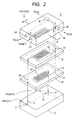
- FIG. 2 illustrates the configuration of the microfluidic device 2 for emulsification.
- the microfluidic device 2 for emulsification is comprised of four stacked components: a liquid introduction portion 10, a disperse phase distribution portion 20, a continuous phase distribution portion 30, and a liquid discharge portion 40. Minute flow paths for producing emulsion are formed by stacking together these components in order. To prevent liquid from leaking out of a flow path, it is required to bring the components into tight contact with one another. There is no special limitation on the material of each component. When each component is fabricated of resin material, for example, adhesive may be used to bring the components into tight contact with one another.
- each component is provided with packing grooves and bolt holes, neither of which is shown in the drawing; rubber packing is placed between components; and the entire components are fastened together by bolts penetrating all the components.
- the proper diameter of the disperse phase processing flow paths 22 and the globule production flow paths 32 differs depending on the property (viscosity and the like) of material or a desired diameter or quantity of globules; therefore, the combination of the components can be changed as required by preparing multiple kinds of the disperse phase distribution portion 20 or the continuous phase distribution portion 30 different in diameter. Some examples of usage of the stack structure will be taken.
- the diameter of globules is controlled by flow control and it is desired to get out of the control range of the diameter, it can be coped with by using disperse phase processing flow paths 22 and globule production flow paths 32 different in diameter.
- liquid introduction portion 10 and the liquid discharge portion 40 that are components connected with the outside are separate from each other. Therefore, they can be easily replaced with a component having a connection method (the size of screws and the like) matched with external equipment to be connected and they can be connected to various liquid sending systems.
- a disperse phase processing flow path 22 or a globule production flow path 32 that is a minute nozzle is choked or damaged, it can be quickly recovered by replacing the relevant component with a new one.
- dirt and precipitate can be more reliably removed than by in-line cleaning by taking the following measure: the microfluidic device is disassembled into individual components and each component is immersed in cleaning liquid and subjected to ultrasonic cleaning.
- the liquid introduction portion 10 is provided with a continuous phase port 11 and a disperse phase port 12.
- the continuous phase port 11 is connected to the continuous phase pump 71 and the disperse phase port 12 is connected to the disperse phase pump 72 respectively by pipes and joints, neither of which is shown in the drawing. They discharge raw material and cleaning liquid sent by pumps from a continuous phase supply opening 13 and a disperse phase supply opening 14 into the disperse phase distribution portion 20 positioned in the immediately upper layer.
- FIG. 3 is a top view of the disperse phase distribution portion 20.
- the disperse phase distribution portion 20 has a meandering disperse phase main flow path 21 on the surface (under surface) in contact with the liquid introduction portion 10.
- the disperse phase main flow path 21 originates directly above the disperse phase supply opening 14 and meanders and goes through all the minute disperse phase processing flow paths 22. Then it runs into a disperse phase discharge opening 23 which is a hole connecting to the continuous phase distribution portion 30.
- the disperse phase discharge opening 23 has the same radial dimensions as those of the disperse phase main flow path 21.
- the disperse phase processing flow paths 22 are minute holes (nozzle-like openings) extended from the disperse phase main flow path 21 to the top face of the disperse phase distribution portion 20.
- the drawing illustrates a case where 40 flow paths, that is, 10 flow paths x 4 rows, are provided.
- the number of required nozzles is increased with increase in the desired quantity of produced emulsion; therefore, the number of the disperse phase processing flow paths 22 is adjusted by appropriately adjusting the number of rows and the number of nozzles per row with the overall size of the microfluidic device 2 for emulsification taken into account.
- the diameter of the disperse phase processing flow paths 22 is appropriately adjusted in accordance with the desired globule diameter of emulsion.
- the diameter of the disperse phase processing flow paths 22 should be equal to a desired globule diameter or should be appropriately twice the desired globule diameter at most.
- the disperse phase main flow path 21 undertakes a role of a buffer for uniformly supplying liquid to the multiple disperse phase processing flow paths 22; therefore, it must be a sufficiently large flow path lower in pressure loss than the disperse phase processing flow paths 22.
- the microfluidic device 2 for emulsification in this embodiment controls globule diameter by the flow ratio between a continuous phase and a disperse phase. To obtain uniform emulsion, therefore, it is required to make uniform the quantity of flow discharged from each disperse phase processing flow path 22.
- the size of the disperse phase main flow path 21 is determined so that the following is implemented: the flow rate error from nozzle to nozzle is suppressed to several % or below according to the number or flow path resistance of the disperse phase processing flow paths 22.
- main flow path resistance nozzle portion (processing flow path) resistance is 1:10000 to 100000 or so.
- main flow path 21 is configured as a rectangle 1 mm or above on a side.
- the disperse phase main flow path 21 is formed in a meandering shape.
- any other shape such as straight shape or spiral shape, may be adopted as long as the following conditions hold: the disperse phase main flow path is far lower in flow path resistance than the nozzle portions; it is in the shape of one single consecutive body without a branch at the same level in flow path resistance as the nozzle portions; and it has a smooth structure without projections or depressions.
- a continuous phase passage opening 24 open in a position away from the disperse phase main flow path 21 is positioned directly above the continuous phase supply opening 13. It provides a flow path when liquid discharged from the continuous phase supply opening 13 is sent to the continuous phase distribution portion 30.
- FIG. 4 is a top view of the continuous phase distribution portion 30.
- the continuous phase distribution portion 30 has a meandering continuous phase main flow path 31 on the surface (under surface) in contact with the disperse phase distribution portion 20.
- the continuous phase main flow path 31 originates directly above the continuous phase passage opening 24 and meanders so that all the globule production flow paths (nozzles) 32 (described later) are sandwiched from left and right. It then runs into a continuous phase discharge opening 33 that is a hole continues to the liquid discharge portion 40. (Refer to FIG. 2 .)
- the continuous phase discharge opening 33 has the same radial dimensions as those of the continuous phase main flow path 31.
- minute continuous phase processing flow paths 34 are provided.
- the continuous phase processing flow paths 34 are smaller in dimensions, such as groove depth, than the continuous phase main flow path 31 as a buffer. It is so formed that the liquid filled in the continuous phase main flow path 31 uniformly reaches the globule production flow paths 32 from two directions, left and right, as illustrated by solid lines in the drawing.
- the globule production flow paths 32 are minute holes positioned directly above the disperse phase processing flow paths 22 positioned in the immediately lower layer and extended from the continuous phase processing flow paths 34 to the top face of the continuous phase distribution portion 30. The same number of the globule production flow paths 32 as that of the disperse phase processing flow paths 22 are formed. In the globule production flow paths 32, as described later, the continuous phase flowing in from left and right and the disperse phase discharged from the opposite disperse phase processing flow paths 22 are merged to form a sheath flow 50 (describe later).
- the diameter of the globule production flow paths 32 on the receiving side are smaller in diameter than the disperse phase processing flow paths 22 on the discharge side at this time, the inside diameter is reduced and the stability of sheath flow 50 formation is degraded. To cope with this, it is desirable that the diameter of the globule production flow paths 32 should be equal to or larger than the diameter of the disperse phase processing flow paths 22.
- the continuous phase main flow path 31 undertakes a role of a buffer for uniformly supplying liquid to the multiple globule production flow paths 32. Therefore, it is required that it should be a flow path having a sufficiently large section lower in pressure loss than the flow paths obtained by combining the globule production flow paths 32 and the continuous phase processing flow paths 34. For the reason described in relation to the disperse phase distribution portion 20, it is required to make uniform the flow rate of the continuous phase sent to each globule production flow path 32 in order to obtain uniform emulsion.
- the size of the continuous phase main flow path 31 is determined so that the following is implemented: the flow rate error of the continuous phase flowing into each flow path is suppressed to several % or below according to the following: the number of the globule production flow paths 32, the total flow path resistance of the globule production flow paths 32 and the continuous phase processing flow paths 34, and the like.
- Both the end portions 36 of the continuous phase main flow path 31 are wider than the central portion of the flow path as illustrated in the drawing. The reason for this will be described below. As seen from the drawing, both the end portions 36 are in contact with only globule production flow paths 32 equivalent to one row. Therefore, its pressure resistance arising from the combination of the globule production flow paths 32 and the continuous phase processing flow paths 34 is half of that of the central portion in contact with globule production flow paths 32 equivalent to two rows.
- the continuous phase main flow path 31 may have any other shape, such as straight shape or spiral shape, as long as the following conditions hold: it is far lower in flow path resistance than the processing flow path portions; it is in the shape of one single consecutive body without a branch at the same level in flow path resistance; and it has a smooth structure without projections or depressions.
- a disperse phase passage opening 37 open in a position away from the continuous phase main flow path 31 is positioned directly above the disperse phase discharge opening 23. It provides a flow path when liquid discharged from the disperse phase discharge opening 23 is sent to the liquid discharge portion 40.
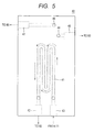
- FIG. 5 is a top view of the liquid discharge portion 40.
- the liquid discharge portion 40 has a meandering emulsion main flow path 41 on the surface (under surface) in contact with the continuous phase distribution portion 30. Both the ends of the emulsion main flow path 41 are connected to an emulsion discharge opening 42 and an emulsion flow path cleaning opening 43 and the emulsion main flow path is formed in a meandering shape so as to cover all the globule production flow paths 32.
- the produced emulsion discharged from each globule production flow path 32 are merged through the emulsion main flow path 41 and guided to the emulsion discharge opening 42. It is then discharged to outside the microfluidic device 2 for emulsification.
- the emulsion main flow path 41 should be low in flow path resistance. In this embodiment, its dimensions are made equal to those of the disperse phase main flow path 21.
- the liquid discharge portion 40 includes the following structure to carry out priming and cleaning.
- the emulsion flow path cleaning opening 43 is provided as an introduction opening for filling the emulsion main flow path 41 with liquid sent from the continuous phase pump 71.
- a continuous phase discharge port 44 is positioned directly above the continuous phase discharge opening 33 and guides liquid discharged from the continuous phase discharge opening 33 to a continuous phase exhaust opening 45. It then discharges the liquid to outside the microfluidic device 2 for emulsification.
- a disperse phase discharge port 46 is positioned directly above the disperse phase passage opening 37 and guides liquid passed through the disperse phase passage opening 37 to a disperse phase exhaust opening 47. It then discharges the liquid to outside the microfluidic device 2 for emulsification.
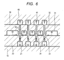
- FIG. 6 is an enlarged sectional view taken along line A-A of FIG. 2 , illustrating the assembled microfluidic device 2 for emulsification; and
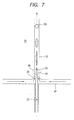
- FIG. 7 is an enlarged sectional view of the globule production portion encircled with a dotted line and indicated by reference numeral 25 in FIG. 6 .
- the globule production portion 25 is comprised of: a disperse phase processing flow path 22 vertically (upwardly) placed in the disperse phase distribution portion 20 so as to send the disperse phase upward; a continuous phase processing flow path 34 placed in the continuous phase distribution portion so that the continuous phase is horizontally merged into this disperse phase processing flow path 22 from left and right; and a globule production flow path 32 vertically (upwardly) placed in the liquid discharge portion 40 so as to let the merged globules flow upward and send them to the emulsion main flow path 41.
- the double circle indicates the flow of liquid from the far side to the near side
- the circled X indicates the flow of liquid from the near side to the far side.
- the disperse phase goes from the disperse phase port 12 to the disperse phase distribution portion 20 by way of the disperse phase supply opening 14 and the like. It thereby pushes out the air in the disperse phase main flow path 21 and fills the main flow path. After the disperse phase fills the main flow path, it goes through the disperse phased discharge opening 23 and moves to outside the microfluidic device 2 for emulsification by way of the disperse phase exhaust opening 47 in the liquid discharge portion 40. It then reaches the waste liquid tank 95 by way of an open main flow path opening/closing valve 83.
- the respective main flow paths 31, 21 for the continuous phase and the disperse phase are filled with the liquids.
- the portions of the disperse phase processing flow paths 22 and the globule production flow paths 32 are far higher in flow path resistance than the main flow paths as mentioned above. Therefore, the liquids flows only through the main flow paths.
- the main flow paths are in the shape of a smooth meandering consecutive body that does not have a branch at the same level in flow path resistance or projections or depressions. Therefore, the air in the main flow paths does not remain and is exhausted and priming can be reliably carried out.
- the two main flow path opening/closing valves 83 are closed.
- the liquids of the continuous phase and the disperse phase are sent from the continuous phase pump 71 and the disperse phase pump 72 to the microfluidic device 2 for emulsification.
- the flow path resistance of the flow path portions is higher than the resistance of the main flow path portions. Therefore, the outputs of the pressure sensors 61 are observed and the quantities of sent liquids are appropriately adjusted so that the pressure limit of the machine is not exceeded. Since each main flow path is filled with liquid and the main flow path opening/closing valves 83 are closed, the sent continuous phase and disperse phase flow into the minute flow path portions.
- the continuous phase enters the continuous phase processing flow paths 34 from two directions, left and right. After merging, it moves upward in the globule production flow paths 32 and passes it through and reaches the emulsion main flow path 41.
- the disperse phase fills the disperse phase processing flow paths 22 and moves upward. It merges with the continuous phase in the globule production flow paths 32 and moves upward and reaches the emulsion main flow path 41.
- the liquid that reached the emulsion main flow path 41 is discharged from the emulsion discharge opening 42 to outside the microfluidic device 2 for emulsification. It is then discarded into the waste liquid tank 95 by way of the product/waste liquid change-over valve 82.
- the sent continuous phase enters the microfluidic device 2 for emulsification from the emulsion flow path cleaning opening 43 and carries away air and liquid in the emulsion main flow path 41. Thereafter, it is discharged from the emulsion discharge opening 42 to outside the microfluidic device 2 for emulsification and discarded into the waste liquid tank 95 by way of the product/waste liquid change-over valve 82.
- the globule production flow paths 32 are far higher in flow path resistance than the emulsion main flow path 41. Therefore, the sent continuous phase flows only through the main flow path and does not flow back to the flow paths.
- the main flow path 41 is in a smooth meandering shape without a branch at the same level in flow path resistance or projections or depressions. Therefore, the air in the main flow path does not remain and is exhausted and priming can be reliably carried out.
- the air in the microfluidic device 2 for emulsification is removed by carrying out the above-mentioned steps and priming is completed.
- the continuous phase and disperse phase sent to the microfluidic device 2 for emulsification are processed as in the above-mentioned priming.
- Each main flow path 21, 31 is used as a buffer and the processing illustrated in FIG. 6 and FIG. 7 is carried out. That is, the continuous phase is uniformly sent to all the continuous phase processing flow paths 34 from left and right; and the disperse phase is uniformly sent from downward to upward through the disperse phase processing flow paths 22. Then they are merged together and emulsion is formed in the globule production flow paths 32.
- the continuous phase processing flow paths 34 are orthogonal to the disperse phase processing flow paths 22.
- the continuous phase and disperse phase merged in the areas where the flow paths intersect with each other form a sheath flow 50.
- oil as the disperse phase forms a center flow 51 positioned inside and water as the continuous phase forms a covering flow 52 positioned outside.
- the globule production flow paths 32 are minute flow paths of the order of micrometer, the sheath flow 50 flowing there becomes a stable laminar flow whose Reynolds number is several hundreds or below. Therefore, the two-layer structure in which the continuous phase sheathes the disperse phase can be maintained. As this sheath flow 50 flows through the globule production flow paths 32, the fluctuation of the liquid-liquid interface caused by a difference in the velocity of flow between the continuous phase and the disperse phase is increased. As a result, the disperse phase is divided and an O/W emulsion 53 constant in globule diameter is obtained. The produced O/W emulsion 53 reaches the emulsion main flow path 41 ( FIG. 6 ).
- the OIW emulsion 53 merges with the emulsion produced at the other globule production flow paths 32 and discharged from the emulsion discharge opening 42 to outside the microfluidic device 2 for emulsification. Then it is stored in the product tank 94 by way of the product/waste liquid change-over valve 82.
- the particle diameter of the produced emulsion is influenced by multiple parameters.
- Such parameters include the diameters of the disperse phase processing flow paths 22 and the globule production flow paths 32, the velocity of flow ratio between the continuous phase and the disperse phase, viscosity, and the like.
- the viscosity of the disperse phase becomes higher than conventional, energy required for dividing it is increased. To maintain a certain globule diameter, therefore, it is required to send a larger quantity of the continuous phase.
- the simplest method for controlling particle diameter in this situation is to control the flow rates of the disperse phase and the continuous phase to vary the velocity of flow in a sheath flow. For example, when the flow rate of the disperse phase is fixed and the flow rate of the continuous phase is varied, the following takes place: when the flow rate of the continuous phase is increased, the particle diameter of the produced emulsion is reduced; and when the flow rate of the continuous phase is conversely reduced, the particle diameter is increased.
- syringe pumps in which a high pulsating flow is not produced and the pumping quantity is not varied with respect to pressure fluctuation on the secondary side are equipped as the continuous phase pump 71 and the disperse phase pump 72. Then highly accurate flow control is carried out. As a result, precise adjustment of particle diameter can be carried out.
- this embodiment has the following structure: a structure in which the globule production flow paths 32 are equal to or larger than the disperse phase processing flow paths 22 in size and a chamfered portion 35 is provided at the inlet of each globule production flow path 32. Therefore, even when the axis of each disperse phase processing flow path 22 and that of each globule production flow path 32 become misaligned with each other because of a problem of processing, a sheath flow 50 can be formed to some extent. This enhances the robustness of this embodiment. With respect to the sectional shape of each flow path, a shape without a corner is desirable in consideration of the washing efficiency of the cleaning process described later. Therefore, it is desirable that each corner should be circular or, if rectangular, should be rounded.
- this embodiment adopts a structure in which the disperse phase processing flow paths 22 and the globule production flow path 32 as minute flow paths are open upward.
- the precipitate is deposited on the bottom surfaces of the main flow paths 21, 31. Therefore, there is slight precipitate in the minute flow path portions and it is difficult for liquid containing precipitated high-concentration fine particles to flow there. Consequently, the minute flow path portions are not frequently choked with precipitate. Further, even emulsification of a material involving precipitation can be continuously carried out by periodically carrying out the cleaning described later.
- the microfluidic device 2 for emulsification is so structured that it can be disassembled and it is dissembled when deposit is removed by ultrasonic cleaning or the like. This method makes it possible to remove dirt without fail; however, it takes some time to disassemble, clean, and reassemble the device and this shortens the operating time of the machine. Therefore, this method is undesirable. In this embodiment, to cope with this, it is made possible to clean all the flow paths by in-line cleaning without disassembling the device.
- Cleaning is started on the following occasions: when emulsion production processing has been carried out for an arbitrary certain time; or when information of degradation in globule quality, such as fluctuation in globule diameter, is acquired by the monitoring device 62, illustrated in FIG. 1 , that monitors the state of emulsion.
- the continuous phase pump 71 and the disperse phase pump 72 are stopped to interrupt pumping of the materials.
- the setting of the cleaning change-over valves 81 is turned to the cleaning liquid tank 93 position and, in addition, the setting of the product/waste liquid change-over valve 82 is turned to the waste liquid tank 95 position. Then the two main flow path opening/closing valves 83 are opened.
- the continuous phase pump 71 and the disperse phase pump 72 are actuated again to send the cleaning liquids stored in the cleaning liquid tanks 93 are sent to the microfluidic device 2 for emulsification.
- the continuous phase is aqueous and the disperse phase is oleaginous
- two cleaning liquid tanks 93 are provided to respectively send cleaning liquids suitable for them. When a common cleaning liquid is used, the cleaning liquid tanks 93 may be combined into one.
- the continuous phase main flow path 31 and the disperse phase main flow path 21 are cleaned.
- the cleaning liquid for the continuous phase side goes from the continuous phase port 11 to the continuous phase distribution portion 30 by way of the continuous phase passage opening 24 and the like. It carries away the residual liquid, precipitate, and dirt in the continuous phase main flow path 31 and fills the main flow path.
- the cleaning liquid filled in the main flow path goes through the continuous phase discharge opening 33 and moves to outside the microfluidic device 2 for emulsification by way of the continuous phase exhaust opening 45. Then it reaches the waste liquid tank 95 by way of an open main flow path opening/closing valves 83.
- the cleaning liquid for the disperse phase side goes from the disperse phase port 12 to the disperse phase distribution portion 20 by way of the disperse phase supply opening 14 and the like. It carries away the residual liquid, precipitate, and dirt in the disperse phase main flow path 21 and fills the main flow path.
- the cleaning liquid filled in the main flow path goes through the disperse phase discharge opening 23 and moves to outside the microfluidic device 2 for emulsification by way of the disperse phase exhaust opening 47. Then it reaches the waste liquid tank 95 by way of an open main flow path opening/closing valve 83.
- the portions of the disperse phase processing flow paths 22 and the globule production flow paths 32 are far higher in flow path resistance than the main flow paths; therefore, the cleaning liquids flow only through the main flow paths.
- the main flow paths are in a smooth meandering shape without a branch at the same level in flow path resistance or projections or depressions. Therefore, the precipitate or dirt in each main flow path does not remain and is discharged and reliable cleaning can be carried out.
- the minute flow path portions such as the disperse phase processing flow paths 22 and the globule production flow paths 32, are cleaned.
- the two main flow path opening/closing valves 83 are closed and the cleaning liquids are sent from the continuous phase pump 71 and the disperse phase pump 72 to the microfluidic device 2 for emulsification.
- the flow path resistance of the processing flow path portions is higher than the resistance of the main flow path portions. Therefore, the outputs of the pressure sensors 61 are observed and their pumping quantities are appropriately adjusted so that the pressure limit of the machine is not exceeded. Since each main flow path is filled with cleaning liquid and the main flow path opening/closing valves 83 are closed, the sent cleaning liquids flow to the minute flow path portions.
- the cleaning liquids flow as illustrated in FIG. 6 . That is, the cleaning liquid for the continuous phase side enters the continuous phase processing flow paths 34 from two directions, left and right. After merging, it passes through the globule production flow paths 32 to remove dirt and reaches the emulsion main flow path 41.
- the cleaning liquid for the disperse phase side removes dirt in the disperse phase processing flow paths 22 and moves upward. It merges with the continuous phase at the globule production flow paths 32 and reaches the emulsion main flow path 41.
- the liquid that reached the emulsion main flow path 41 is discharged from the emulsion discharge opening 42 to outside the microfluidic device 2 for emulsification and is discarded into the waste liquid tank 95 by way of the product/waste liquid change-over valve 82.
- the main flow paths fulfill a role of a buffer and it is thereby made possible to uniformly send liquid to the multiple flow path portions. Therefore, all the flow path portions can be reliably cleaned.
- the emulsion main flow path 41 is cleaned.
- the setting of the outlet flow path change-over valve 84 is turned to the emulsion flow path cleaning opening 43 position and only the continuous phase pump 71 is operated. Then the output of the appropriate pressure sensor 61 is observed and the cleaning liquid is sent to the extent that the pressure limit of the machine is not exceeded.
- the sent cleaning liquid enters the microfluidic device 2 for emulsification from the emulsion flow path cleaning opening 43 and carries away the dirt, precipitate, and residual liquid in the emulsion main flow path 41.
- the globule production flow paths 32 are far higher in flow path resistance than the emulsion main flow path 41; therefore, the sent cleaning liquid flows only through the main flow path and does not flow back to the flow path side.
- the main flow path 41 is in a smooth meandering shape without a branch at the same level in flow path resistance or projections or depressions; therefore, the dirt, precipitate, or residual liquid does not remain in the main flow path and they are discharged. Thus cleaning can be reliably carried out.
- all the flow paths can be reliably cleaned in a short time without disassembling the device by carrying out cleaning in stages.
- the following pipes are fixed so that they are directed to under the microfluidic device 2 for emulsification and are shortened as much as possible: the pipes between the continuous phase exhaust opening 45 and the corresponding main flow path opening/closing valve 83, between the disperse phase exhaust opening 47 and the corresponding main flow path opening/closing valve 83, and between the emulsion discharge opening 42 and the product/waste liquid change-over valve 82.
- the microfluidic device 2 for emulsification is equipped with an ultrasonic generator 63 ( FIG. 1 ).
- the effect of cleaning can be further enhanced by actuating it while cleaning liquid is being sent to apply microvibration to the interior of each flow path to lift precipitate and dirt.
- the cleaning liquid in the pipes and the microfluidic device 2 for emulsification is replaced with the continuous phase and the disperse phase.
- the setting of the cleaning change-over valves 81 is turned to the continuous phase tank 91 position and the disperse phase tank 92 position.
- the two main flow path opening/closing valves 83 are opened and the setting of the outlet flow path change-over valve 84 is turned to the continuous phase port 11 position.
- the continuous phase pump 71 and the disperse phase pump 72 are actuated.
- the continuous phase and the disperse phase respectively stored in the continuous phase tank 91 and the disperse phase tank 92 are thereby sent to the microfluidic device 2 for emulsification.
- the cleaning liquids in the continuous phase main flow path 31 and the disperse phase main flow path 21 are replaced with the continuous phase and the disperse phase.
- the two main flow path opening/closing valves 83 are closed and the liquids are sent from the continuous phase pump 71 and the disperse phase pump 72 at the pumping quantities for emulsion production processing.
- the sent liquid produces emulsion having a desired globule diameter and replaces the cleaning liquid in the minute flow path portions, such as the globule production flow paths 32, and the emulsion main flow path 41.
- the liquid sending for substitution is continued until it can be determined from an output result from the monitoring device 62 that the emulsion has been brought into a desired state. When the emulsion is stabilized, the substitution is terminated.
- the setting of the product/waste liquid change-over valve 82 is turned to the product tank 94 position to start the storage of the emulsion.
- the following can be implemented by periodically carrying out the above-mentioned processing from cleaning to substitution: the internal state of the microfluidic device 2 for emulsification can be refreshed and stable emulsion can be produced for a long time.
- the two main flow path opening/closing valves 83 are closed and high-pressure air is sent again.
- most residual liquid in the minute flow path portions, such as the globule production flow paths 32, and the emulsion main flow path 41 is purged into the waste liquid tank 95.
- the setting of the outlet flow path change-over valve 84 is turned to the emulsion flow path cleaning opening 43 position and high-pressure air is sent.
- the residual liquid in the emulsion main flow path 41 is completely purged.
- the flow paths in the microfluidic device 2 for emulsification are cleaned and residual liquid is removed. This completes the shutdown operation of the machine.
- the invention can also be applied to other modes, including a multiple-stage configuration in which multiple processing devices are provided in series and multiple different kinds of continuous phase liquids are sent in stages to produce a multilayer emulsion.
Landscapes
- Chemical & Material Sciences (AREA)
- Chemical Kinetics & Catalysis (AREA)
- Micromachines (AREA)
- Accessories For Mixers (AREA)
- Physical Or Chemical Processes And Apparatus (AREA)
Claims (12)
- Emulgiermaschine, die mit einer mikrofluiden Vorrichtung (2) ausgestattet ist, die dazu geeignet ist, einen Mantelstrom zu bilden, in welchem eine kontinuierliche Phase als zweite Flüssigkeit den Umfang einer disperse Phase als erste Flüssigkeit in einem Fließweg (22) einkreist und die disperse Phase durch eine Geschwindigkeitsdifferenz zwischen der dispersen Phase und der kontinuierlichen Phase zur Herstellung einer Emulsion teilt und in Kügelchen umwandelt,
wobei die mikrofluide Vorrichtung (2) einschließt:einen Disperse-Phase-Hauptfließweg (21), um die disperse Phase durchzulassen;mehrere Disperse-Phase-Verarbeitungsfließwege (22), die sich vom Disperse-Phase-Hauptfließweg (21) verzweigen und die disperse Phase verteilen und senden;einen Kontinuierliche-Phase-Hauptfließweg (31), um die kontinuierliche Phase durchzulassen;mehrere Kontinuierliche-Phase-Verarbeitungsfließwege (34), die sich vom Kontinuierliche-Phase-Hauptfließweg (31) verzweigen und die kontinuierliche Phase verteilen und senden;mehrere Kügelchen-Herstellungsbereiche, die die disperse Phase und die kontinuierliche Phase zur Herstellung von Emulsionskügelchen in Bereichen miteinander verschmelzen, in denen die Disperse-Phase-Verarbeitungsfließwege (22) und die Kontinuierliche-Phase-Verarbeitungsfließwege (34) einander schneiden;einen Emulsionshauptfließweg (41) zum Verschmelzen von Kügelchen, die in den Kügelchen-Herstellungsbereichen hergestellt sind, und Senden der Kügelchen nach außen; und Pumpen (71, 72), die jeweils in einem Fließweg, der mit dem Disperse-Phase-Hauptfließweg (21) verbunden ist, und einem Fließweg, der mit dem Kontinuierliche-Phase-Hauptfließweg (31) verbunden ist, vorgesehen sind und Flüssigkeiten pumpen, die durch diese Hauptfließwege (21, 31) fließen;dadurch gekennzeichnet, dass die Emulgiermaschine ferner umfasst:Hauptfließwegöffnungs-/-schließventile (83), die jeweils auf der Auslassöffnungsseite des Disperse-Phase-Hauptfließwegs (21) und des Kontinuierliche-Phase-Hauptfließwegs (31) vorgesehen sind;ein Produkt-/Abfallflüssigkeits-Umschaltventil (82), das vom Emulsionshauptfließweg (41) gesendete Flüssigkeit zwischen der Produktseite und der Abfallflüssigkeitsseite umschaltet;eine Überwachungsvorrichtung (62), die den Emulsionszustand überwacht;Drucksensoren (61), die jeweils die inneren Drücke des Disperse-Phase-Hauptfließwegs (21) und des Kontinuierliche-Phase-Hauptfließwegs (31) überwachen; undeine Steuereinheit, die die Pumpen (71, 72), die Hauptfließwegöffnungs-/-schließventile (83) und das Produkt-/Abfallflüssigkeits-Umschaltventil (82) auf der Basis von Signalen von der Überwachungsvorrichtung (62) und der Drucksensoren (61) steuert. - Emulgiermaschine nach Anspruch 1,
wobei die Disperse-Phase-Verarbeitungsfließwege (22) so angeordnet sind, dass sie die disperse Phase von abwärts nach aufwärts fließen lassen,
wobei die Kontinuierliche-Phase-Verarbeitungsfließwege (34) so angeordnet sind, dass sie lateral mit der dispersen Phase verschmelzen, und
wobei die Kügelchen-Herstellungsbereiche mit Kügelchen-Herstellungsfließwegen (32) versehen sind, um Kügelchen nach dem Verschmelzen aufwärts fließen zu lassen und diese an den Emulsionshauptfließweg (41) zu senden. - Emulgiermaschine nach Anspruch 1 oder 2,
wobei die mikrofluide Vorrichtung (2) einschließt:einen Disperse-Phase-Verteilungsbereich (20) mit dem Disperse-Phase-Hauptfließweg (21) und den aufwärts gewandten Disperse-Phase-Verarbeitungsfließwegen (22), die von dem Disperse-Phase-Hauptfließweg (21) verzweigt sind;einem Kontinuierliche-Phase-Verteilungsbereich (30) mit dem Kontinuierliche-Phase-Hauptfließweg (31), den seitlich gewandten Kontinuierliche-Phase-Verarbeitungsfließwegen (34), die von dem Kontinuierliche-Phase-Hauptfließweg (31) verzweigt sind, und aufwärts gewandten Kügelchen-Herstellungsfließwegen (32), die zu den Kontinuierliche-Phase-Verarbeitungsfließwegen (34) verlaufen; undeinem Flüssigkeitsauslassbereich (40) mit dem EmulsionsHauptfließweg (41), undwobei der Kontinuierliche-Phase-Verteilungsbereich (30) über dem Disperse-Phase-Verteilungsbereich (20) gestapelt ist und der Flüssigkeitsauslassbereich (40) über diesem gestapelt ist. - Emulgiermaschine nach Anspruch 3,
wobei die Kügelchen-Herstellungsbereiche in dem Bereich des Stapelns des Disperse-Phase-Verteilungsbereichs (20) und des Kontinuierliche-Phase-Verteilungsbereichs (30) ausgebildet sind, und
wobei die Disperse-Phase-Verarbeitungsfließwege (22), Kontinuierliche-Phase-Verarbeitungsfließwege (34) und Kügelchen-Herstellungsfließwege (32) veranlasst werden, mit den Kügelchen-Herstellungsbereichen in Verbindung zu treten. - Emulgiermaschine nach Anspruch 2,
wobei der Durchmesser der Kügelchen-Herstellungsfließwege (32) nach dem Verschmelzen gleich oder größer als der Durchmesser der Disperse-Phase-Herstellungsfließwege (22) vor dem Verschmelzen in den Kügelchen-Herstellungsbereichen ist und der Einlass von jedem der Kügelchen-Herstellungsfließwege (32) nach dem Verschmelzen zu einer Trichterform abgefast wird. - Emulgiermaschine nach Anspruch 4,
wobei der Durchmesser der Kügelchen-Herstellungsfließwege (32) nach dem Verschmelzen gleich oder größer als der Durchmesser der Disperse-Phase-Herstellungsfließwege (22) vor dem Verschmelzen in den Kügelchen-Herstellungsbereichen ist und der Einlass von jedem der Kügelchen-Herstellungsfließwege (32) nach dem Verschmelzen zu einer Trichterform abgefast wird. - Emulgiermaschine nach einem der vorhergehenden Ansprüche,
wobei der Kontinuierliche-Phase-Hauptfließweg (31) in einer derartigen mäandernden Form ausgebildet ist, dass die Disperse-Phase-Verarbeitungsfließwege (22) von beiden Seiten so sandwichartig umschlossen sind, dass Flüssigkeit von den Kontinuierliche-Phase-Verarbeitungsfließwegen (34) zu beiden Seitenflächen von jedem der Disperse-Phase-Verarbeitungsfließwege (22) gesendet werden kann, die vertikal angeordnet sind, und
wobei die geraden Bereiche des Kontinuierliche-Phase-Hauptfließwegs (31), die an beiden Enden in der Breitenrichtung positioniert sind, breiter als dessen gerade Bereiche sind, die in der Mitte der Breitenrichtung positioniert sind. - Emulgiermaschine nach Anspruch 2 oder 5,
wobei die Kügelchen-Herstellungsbereiche ferner zweite Kontinuierliche-Phase-Verarbeitungsfließwege (34) einschließen, die sich mit den Kügelchen-Herstellungsfließwegen (32) schneiden, zusätzlich zu den Kontinuierliche-Phase-Verarbeitungsfließwegen (34), die sich mit den Disperse-Phase-Verarbeitungsfließwegen (22) schneiden, und
wobei ein mehrschichtiger Mantelstrom, in welchem der Umfang eines Mantelstroms, der in den Bereichen des Verschmelzens der Disperse-Phase-Verarbeitungsfließwege (22) und der Kontinuierliche-Phase-Verarbeitungsfließwege (34) gebildet ist, mit einer kontinuierlichen Phase von den zweiten Kontinuierliche-Phase-Verarbeitungsfließwegen (34) eingekreist ist, zur Herstellung einer mehrschichtigen Emulsion gebildet ist. - Emulgiermaschine nach Anspruch 4 oder 6,
wobei die Kügelchen-Herstellungsbereiche ferner zweite Kontinuierliche-Phase-Verarbeitungsfließwege (34) einschließen, die sich mit den Kügelchen-Herstellungsfließwegen (32) schneiden, zusätzlich zu den Kontinuierliche-Phase-Verarbeitungsfließwegen (34), die sich mit den Disperse-Phase-Verarbeitungsfließwegen (22) schneiden, und
wobei ein mehrschichtiger Mantelstrom, in welchem der Umfang eines Mantelstroms, der in den Bereichen des Verschmelzens der Disperse-Phase-Verarbeitungsfließwege (22) und der Kontinuierliche-Phase-Verarbeitungsfließwege (34) gebildet ist, mit einer kontinuierlichen Phase von den zweiten Kontinuierliche-Phase-Verarbeitungsfließwegen (34) eingekreist ist, zur Herstellung einer mehrschichtigen Emulsion gebildet ist. - Emulgiermaschine nach Anspruch 5,
wobei die Kügelchen-Herstellungsbereiche ferner zweite Kontinuierliche-Phase-Verarbeitungsfließwege (34) einschließen, die sich mit den Kügelchen-Herstellungsfließwegen (32) schneiden, zusätzlich zu den Kontinuierliche-Phase-Verarbeitungsfließwegen (34), die sich mit den Disperse-Phase-Verarbeitungsfließwegen (22) schneiden, und
wobei ein mehrschichtiger Mantelstrom, in welchem der Umfang eines Mantelstroms, der in den Bereichen des Verschmelzens der Disperse-Phase-Verarbeitungsfließwege (22) und der Kontinuierliche-Phase-Verarbeitungsfließwege (34) gebildet ist, mit einer kontinuierlichen Phase von den zweiten Kontinuierliche-Phase-Verarbeitungsfließwegen (34) eingekreist ist, zur Herstellung einer mehrschichtigen Emulsion gebildet ist. - Emulgiermaschine nach Anspruch 7,
wobei die Kügelchen-Herstellungsbereiche ferner zweite Kontinuierliche-Phase-Verarbeitungsfließwege (34) einschließen, die sich mit den Kügelchen-Herstellungsfließwegen (32) schneiden, zusätzlich zu den Kontinuierliche-Phase-Verarbeitungsfließwegen (34), die sich mit den Disperse-Phase-Verarbeitungsfließwegen (22) schneiden, und
wobei ein mehrschichtiger Mantelstrom, in welchem der Umfang eines Mantelstroms, der in den Bereichen des Verschmelzens der Disperse-Phase-Verarbeitungsfließwege (22) und der Kontinuierliche-Phase-Verarbeitungsfließwege (34) gebildet ist, mit einer kontinuierlichen Phase von den zweiten Kontinuierliche-Phase-Verarbeitungsfließwegen (34) eingekreist ist, zur Herstellung einer mehrschichtigen Emulsion gebildet ist. - Emulgierverfahren zum Bilden eines Mantelstroms, in welchem eine kontinuierliche Phase als zweite Flüssigkeit den Umfang einer disperse Phase als erste Flüssigkeit in einem Fließweg (22) einkreist, der in einer mikrofluiden Vorrichtung (2) ausgebildet ist, und die disperse Phase durch eine Geschwindigkeitsdifferenz zwischen der dispersen Phase und der kontinuierlichen Phase zur Herstellung einer Emulsion teilt und in Kügelchen umwandelt,
wobei in der mikrofluiden Vorrichtung (2) ausgebildet sind:ein Disperse-Phase-Hauptfließweg (21), um die disperse Phase durchzulassen;mehrere Disperse-Phase-Verarbeitungsfließwege (22), die sich vom Disperse-Phase-Hauptfließweg (21) verzweigen und die disperse Phase verteilen und senden;ein Kontinuierliche-Phase-Hauptfließweg (31), um die kontinuierliche Phase durchzulassen;mehrere Kontinuierliche-Phase-Verarbeitungsfließwege (34), die sich vom Kontinuierliche-Phase-Hauptfließweg (31) verzweigen und die kontinuierliche Phase verteilen und senden;mehrere Kügelchen-Herstellungsbereiche, die die disperse Phase und die kontinuierliche Phase zur Herstellung von Emulsionskügelchen in Bereichen miteinander verschmelzen, in denen die Disperse-Phase-Verarbeitungsfließwege (22) und die Kontinuierliche-Phase-Verarbeitungsfließwege (34) zur Herstellung von Emulsionskügelchen einander schneiden;ein Emulsionshauptfließweg (41) zum Verschmelzen der Kügelchen, die in den Kügelchen-Herstellungsbereichen hergestellt sind, und Senden der Kügelchen nach außen,wobei ein Fließweg, der mit dem Disperse-Phase-Hauptfließweg (21) verbunden ist, und ein Fließweg, der mit der Kontinuierliche-Phase-Hauptfließweg (31) verbunden ist, jeweils mit Pumpen (71, 72) versehen sind, um in ihnen fließende Flüssigkeiten zu pumpen,dadurch gekennzeichnet, dass Hauptfließwegöffnungs/-schließventile (83) jeweils auf der Auslassöffnungsseite des Disperse-Phase-Hauptfließwegs (21) und des Kontinuierliche-Phase-Hauptfließwegs (31) vorgesehen sind;wobei ein Produkt-/Abfallflüssigkeits-Umschaltventil (82) auf der Auslassseite des Emulsionshauptfließwegs (41) vorgesehen ist, um gesendete Flüssigkeit zwischen der Produktseite und der Abfallflüssigkeitsseite umzuschalten, wobei das Verfahren umfasst:Öffnen der Hauptfließwegöffnungs-/-schließventile (83) und Drehen der Einstellung des Produkt-/Abfallflüssigkeits-Umschaltventils (82) in die Abfallflüssigkeitsposition, wenn ein Auffüllen zum Entfernen von Luft in jedem der Fließwege und ein Reinigen zum Entfernen von Schmutz, wie etwa Präzipitat, ausgeführt wird;Zuführen von entweder der kontinuierlichen Phase, der dispersen Phase oder von Reinigungsflüssigkeit in jeden der Hauptfließwege durch die Pumpen (71, 72),anschließend Schließen der Hauptfließwegöffnungs-/-schließventile (83) und Zuführen von entweder der kontinuierlichen Phase, der dispersen Phase oder von Reinigungsflüssigkeit zu den Verarbeitungsfließwegen und den Kügelchen-Herstellungsbereichen durch die Pumpen (71, 72),anschließend Öffnen des Auslassfließweg-Umschaltventils (82) zum Senden der kontinuierlichen Phase, der dispersen Phase oder von Reinigungsflüssigkeit an den Emulsionshauptfließweg (41) durch die Pumpen; unddanach Ausführen der Emulgierung.
Applications Claiming Priority (1)
| Application Number | Priority Date | Filing Date | Title |
|---|---|---|---|
| JP2009192991A JP5212313B2 (ja) | 2009-08-24 | 2009-08-24 | 乳化装置 |
Publications (3)
| Publication Number | Publication Date |
|---|---|
| EP2289613A2 EP2289613A2 (de) | 2011-03-02 |
| EP2289613A3 EP2289613A3 (de) | 2012-06-06 |
| EP2289613B1 true EP2289613B1 (de) | 2013-10-23 |
Family
ID=43242125
Family Applications (1)
| Application Number | Title | Priority Date | Filing Date |
|---|---|---|---|
| EP10170703.2A Not-in-force EP2289613B1 (de) | 2009-08-24 | 2010-07-23 | Emulgiermaschine und -verfahren |
Country Status (3)
| Country | Link |
|---|---|
| US (1) | US20110046243A1 (de) |
| EP (1) | EP2289613B1 (de) |
| JP (1) | JP5212313B2 (de) |
Families Citing this family (27)
| Publication number | Priority date | Publication date | Assignee | Title |
|---|---|---|---|---|
| EP2248578B1 (de) | 2005-03-04 | 2012-06-06 | President and Fellows of Harvard College | Verfahren zur Bildung mehrerer Emulsionen |
| US10512910B2 (en) | 2008-09-23 | 2019-12-24 | Bio-Rad Laboratories, Inc. | Droplet-based analysis method |
| CN102405402A (zh) | 2008-09-23 | 2012-04-04 | 阔达生命有限公司 | 基于液滴的测定系统 |
| US12090480B2 (en) | 2008-09-23 | 2024-09-17 | Bio-Rad Laboratories, Inc. | Partition-based method of analysis |
| US9156010B2 (en) | 2008-09-23 | 2015-10-13 | Bio-Rad Laboratories, Inc. | Droplet-based assay system |
| US11130128B2 (en) | 2008-09-23 | 2021-09-28 | Bio-Rad Laboratories, Inc. | Detection method for a target nucleic acid |
| US9492797B2 (en) | 2008-09-23 | 2016-11-15 | Bio-Rad Laboratories, Inc. | System for detection of spaced droplets |
| US9764322B2 (en) | 2008-09-23 | 2017-09-19 | Bio-Rad Laboratories, Inc. | System for generating droplets with pressure monitoring |
| US12162008B2 (en) | 2008-09-23 | 2024-12-10 | Bio-Rad Laboratories, Inc. | Partition-based method of analysis |
| US20120211084A1 (en) | 2009-09-02 | 2012-08-23 | President And Fellows Of Harvard College | Multiple emulsions created using jetting and other techniques |
| CA2816712C (en) * | 2010-11-01 | 2018-12-11 | Donald A. Masquelier | System for forming emulsions |
| US12097495B2 (en) | 2011-02-18 | 2024-09-24 | Bio-Rad Laboratories, Inc. | Methods and compositions for detecting genetic material |
| EP2714254B1 (de) * | 2011-05-23 | 2017-09-06 | President and Fellows of Harvard College | Kontrolle von emulsionen, einschliesslich mehrerer emulsionen |
| CN103764265A (zh) | 2011-07-06 | 2014-04-30 | 哈佛学院院长等 | 多重乳剂和用于配制多重乳剂的技术 |
| CN102389730A (zh) * | 2011-08-23 | 2012-03-28 | 东南大学 | 一种双重乳液制备芯片 |
| WO2014018562A1 (en) * | 2012-07-23 | 2014-01-30 | Bio-Rad Laboratories, Inc. | Droplet generation system with features for sample positioning |
| KR101491900B1 (ko) * | 2013-03-19 | 2015-02-11 | 한국과학기술원 | 다층 미세유체채널을 이용한 미세조류 스크리닝 장치 및 이를 이용한 미세조류 스크리닝 방법 |
| KR102596508B1 (ko) | 2014-04-10 | 2023-10-30 | 10엑스 제노믹스, 인크. | 시약을 캡슐화 및 구획화하기 위한 유체 디바이스, 시스템, 및 방법, 및 이의 응용 |
| US9975122B2 (en) | 2014-11-05 | 2018-05-22 | 10X Genomics, Inc. | Instrument systems for integrated sample processing |
| EP3222351A1 (de) * | 2016-03-23 | 2017-09-27 | Ecole Polytechnique Fédérale de Lausanne (EPFL) | Mikrofluidische netzwerkvorrichtung |
| WO2017197343A2 (en) | 2016-05-12 | 2017-11-16 | 10X Genomics, Inc. | Microfluidic on-chip filters |
| WO2017197338A1 (en) | 2016-05-13 | 2017-11-16 | 10X Genomics, Inc. | Microfluidic systems and methods of use |
| JP7290592B2 (ja) * | 2020-03-24 | 2023-06-13 | 株式会社日立プラントサービス | マイクロリアクタシステム |
| US20240100492A1 (en) * | 2020-11-30 | 2024-03-28 | Andre Wild | Non aggregating microfluidic mixer and methods therefor |
| US12472481B2 (en) * | 2021-09-10 | 2025-11-18 | Precigenome Llc | Microfluidics-based nanoparticle synthesis system, and device and method using same |
| TW202417109A (zh) * | 2022-10-24 | 2024-05-01 | 大陸商北京劑泰醫藥科技有限公司 | 奈米顆粒製備 |
| CN119140186A (zh) * | 2023-06-16 | 2024-12-17 | 深圳麦科田生物医疗技术股份有限公司 | 微流控芯片 |
Family Cites Families (15)
| Publication number | Priority date | Publication date | Assignee | Title |
|---|---|---|---|---|
| US4533254A (en) * | 1981-04-17 | 1985-08-06 | Biotechnology Development Corporation | Apparatus for forming emulsions |
| US5833364A (en) * | 1993-11-17 | 1998-11-10 | Calgon Corporation | Chemical delivery and on-site blending system for producing multiple products |
| JPH10109024A (ja) * | 1996-10-04 | 1998-04-28 | Jasco Corp | エマルション調整方法及び装置 |
| US7883670B2 (en) * | 2002-02-14 | 2011-02-08 | Battelle Memorial Institute | Methods of making devices by stacking sheets and processes of conducting unit operations using such devices |
| EP1391237B1 (de) * | 2002-08-01 | 2011-09-21 | Tosoh Corporation | Vorrichtung mit feinen Kanälen, miniaturisierte chemische Anlage zur Herstellung feiner Partikel und Vorrichtung zu dessen Verwendung |
| JP4527384B2 (ja) * | 2002-12-06 | 2010-08-18 | 綜研化学株式会社 | マイクロチャンネルを用いた着色球状粒子の製造方法、およびその製造方法に用いるマイクロチャンネル式製造装置 |
| DE20218972U1 (de) * | 2002-12-07 | 2003-02-13 | Ehrfeld Mikrotechnik AG, 55234 Wendelsheim | Statischer Laminationsmikrovermischer |
| JP2004359822A (ja) | 2003-06-04 | 2004-12-24 | Sekisui Chem Co Ltd | 液滴の生成方法および生成装置 |
| JP4713397B2 (ja) | 2006-01-18 | 2011-06-29 | 株式会社リコー | 微小流路構造体及び微小液滴生成システム |
| US20070246106A1 (en) * | 2006-04-25 | 2007-10-25 | Velocys Inc. | Flow Distribution Channels To Control Flow in Process Channels |
| JP2008100182A (ja) * | 2006-10-20 | 2008-05-01 | Hitachi Plant Technologies Ltd | 乳化装置および微粒子製造装置 |
| JP4449997B2 (ja) * | 2007-03-12 | 2010-04-14 | 株式会社日立製作所 | マイクロリアクタシステム |
| JP4226634B2 (ja) * | 2007-03-29 | 2009-02-18 | 財団法人 岡山県産業振興財団 | マイクロリアクター |
| JP4466682B2 (ja) * | 2007-05-28 | 2010-05-26 | 株式会社日立プラントテクノロジー | 流体混合装置 |
| WO2009153115A1 (en) * | 2008-06-20 | 2009-12-23 | Unilever Plc | Apparatus and method for emulsion manufacture |
-
2009
- 2009-08-24 JP JP2009192991A patent/JP5212313B2/ja active Active
-
2010
- 2010-07-23 EP EP10170703.2A patent/EP2289613B1/de not_active Not-in-force
- 2010-07-29 US US12/845,790 patent/US20110046243A1/en not_active Abandoned
Also Published As
| Publication number | Publication date |
|---|---|
| EP2289613A3 (de) | 2012-06-06 |
| EP2289613A2 (de) | 2011-03-02 |
| JP2011041925A (ja) | 2011-03-03 |
| JP5212313B2 (ja) | 2013-06-19 |
| US20110046243A1 (en) | 2011-02-24 |
Similar Documents
| Publication | Publication Date | Title |
|---|---|---|
| EP2289613B1 (de) | Emulgiermaschine und -verfahren | |
| RU2304475C2 (ru) | Устройство для образования пены | |
| US20100020632A1 (en) | Apparatus And Method for Mixing by Producing Shear, Turbulence and/or Cavitation | |
| JP5087146B2 (ja) | ホモジナイザ・バルブ | |
| CN102215946A (zh) | 液体混合装置 | |
| CN104169009B (zh) | 液体材料吐出机构及液体材料吐出装置 | |
| TW201433363A (zh) | 微細氣泡產生噴嘴及微細氣泡產生裝置 | |
| KR200453473Y1 (ko) | 고압력 호모게나이저 | |
| EP1913994A2 (de) | Emulgierungsgerät und Gerät zur Herstellung von Feinkorn | |
| JP2011025148A (ja) | 化学生産装置 | |
| WO2016124164A1 (de) | Mischvorrichtung mit integrierter förderpumpe | |
| DE60027109T2 (de) | Vorrichtung zum Eliminieren von Blasen | |
| JP2015037777A (ja) | 洗米水の浄化方法 | |
| JP6321929B2 (ja) | 洗米方法、洗米装置 | |
| JP2013146714A (ja) | 微細気泡生成装置 | |
| US748971A (en) | of sandusky | |
| JP2018111098A (ja) | 洗米方法、洗米装置、洗米装置の運転方法 | |
| DE60304581T2 (de) | Fluidisiervorrichtung | |
| KR20110072932A (ko) | 연속식 혼합장치를 이용한 재생약액 공급 장치 | |
| CN116113489A (zh) | 在井场混合材料的系统和方法 | |
| CN209287195U (zh) | 一种整理剂调配乳化系统 | |
| EP4382197A3 (de) | Mischsystem und verfahren zum mischen eines primärfluids mit einer fliessfähigen sekundärsubstanz | |
| JP4863832B2 (ja) | 分散液の製造方法および分散液製造用モジュール | |
| JP6999135B2 (ja) | 混合器、ファインバブル含有流体生成装置、気液混相流体流れ形成方法及びファインバブル含有流体生成方法 | |
| JP5762210B2 (ja) | 気体溶解装置および微細気泡生成装置 |
Legal Events
| Date | Code | Title | Description |
|---|---|---|---|
| PUAI | Public reference made under article 153(3) epc to a published international application that has entered the european phase |
Free format text: ORIGINAL CODE: 0009012 |
|
| AK | Designated contracting states |
Kind code of ref document: A2 Designated state(s): AL AT BE BG CH CY CZ DE DK EE ES FI FR GB GR HR HU IE IS IT LI LT LU LV MC MK MT NL NO PL PT RO SE SI SK SM TR |
|
| AX | Request for extension of the european patent |
Extension state: BA ME RS |
|
| PUAL | Search report despatched |
Free format text: ORIGINAL CODE: 0009013 |
|
| AK | Designated contracting states |
Kind code of ref document: A3 Designated state(s): AL AT BE BG CH CY CZ DE DK EE ES FI FR GB GR HR HU IE IS IT LI LT LU LV MC MK MT NL NO PL PT RO SE SI SK SM TR |
|
| AX | Request for extension of the european patent |
Extension state: BA ME RS |
|
| RIC1 | Information provided on ipc code assigned before grant |
Ipc: B01F 13/00 20060101ALI20120503BHEP Ipc: B01F 13/10 20060101ALI20120503BHEP Ipc: B01F 15/00 20060101ALI20120503BHEP Ipc: B01F 3/08 20060101AFI20120503BHEP |
|
| 17P | Request for examination filed |
Effective date: 20121206 |
|
| GRAP | Despatch of communication of intention to grant a patent |
Free format text: ORIGINAL CODE: EPIDOSNIGR1 |
|
| INTG | Intention to grant announced |
Effective date: 20130503 |
|
| GRAS | Grant fee paid |
Free format text: ORIGINAL CODE: EPIDOSNIGR3 |
|
| GRAA | (expected) grant |
Free format text: ORIGINAL CODE: 0009210 |
|
| RAP1 | Party data changed (applicant data changed or rights of an application transferred) |
Owner name: HITACHI PLANT TECHNOLOGIES, LTD. |
|
| AK | Designated contracting states |
Kind code of ref document: B1 Designated state(s): AL AT BE BG CH CY CZ DE DK EE ES FI FR GB GR HR HU IE IS IT LI LT LU LV MC MK MT NL NO PL PT RO SE SI SK SM TR |
|
| REG | Reference to a national code |
Ref country code: GB Ref legal event code: FG4D |
|
| REG | Reference to a national code |
Ref country code: CH Ref legal event code: EP |
|
| REG | Reference to a national code |
Ref country code: AT Ref legal event code: REF Ref document number: 637236 Country of ref document: AT Kind code of ref document: T Effective date: 20131115 |
|
| REG | Reference to a national code |
Ref country code: IE Ref legal event code: FG4D |
|
| REG | Reference to a national code |
Ref country code: DE Ref legal event code: R096 Ref document number: 602010011108 Country of ref document: DE Effective date: 20131219 |
|
| REG | Reference to a national code |
Ref country code: SE Ref legal event code: TRGR |
|
| REG | Reference to a national code |
Ref country code: NL Ref legal event code: VDEP Effective date: 20131023 |
|
| REG | Reference to a national code |
Ref country code: AT Ref legal event code: MK05 Ref document number: 637236 Country of ref document: AT Kind code of ref document: T Effective date: 20131023 |
|
| REG | Reference to a national code |
Ref country code: LT Ref legal event code: MG4D |
|
| PG25 | Lapsed in a contracting state [announced via postgrant information from national office to epo] |
Ref country code: NO Free format text: LAPSE BECAUSE OF FAILURE TO SUBMIT A TRANSLATION OF THE DESCRIPTION OR TO PAY THE FEE WITHIN THE PRESCRIBED TIME-LIMIT Effective date: 20140123 Ref country code: BE Free format text: LAPSE BECAUSE OF FAILURE TO SUBMIT A TRANSLATION OF THE DESCRIPTION OR TO PAY THE FEE WITHIN THE PRESCRIBED TIME-LIMIT Effective date: 20131023 Ref country code: NL Free format text: LAPSE BECAUSE OF FAILURE TO SUBMIT A TRANSLATION OF THE DESCRIPTION OR TO PAY THE FEE WITHIN THE PRESCRIBED TIME-LIMIT Effective date: 20131023 Ref country code: IS Free format text: LAPSE BECAUSE OF FAILURE TO SUBMIT A TRANSLATION OF THE DESCRIPTION OR TO PAY THE FEE WITHIN THE PRESCRIBED TIME-LIMIT Effective date: 20140223 Ref country code: FI Free format text: LAPSE BECAUSE OF FAILURE TO SUBMIT A TRANSLATION OF THE DESCRIPTION OR TO PAY THE FEE WITHIN THE PRESCRIBED TIME-LIMIT Effective date: 20131023 Ref country code: HR Free format text: LAPSE BECAUSE OF FAILURE TO SUBMIT A TRANSLATION OF THE DESCRIPTION OR TO PAY THE FEE WITHIN THE PRESCRIBED TIME-LIMIT Effective date: 20131023 Ref country code: LT Free format text: LAPSE BECAUSE OF FAILURE TO SUBMIT A TRANSLATION OF THE DESCRIPTION OR TO PAY THE FEE WITHIN THE PRESCRIBED TIME-LIMIT Effective date: 20131023 |
|
| RAP2 | Party data changed (patent owner data changed or rights of a patent transferred) |
Owner name: HITACHI, LTD. |
|
| PG25 | Lapsed in a contracting state [announced via postgrant information from national office to epo] |
Ref country code: ES Free format text: LAPSE BECAUSE OF FAILURE TO SUBMIT A TRANSLATION OF THE DESCRIPTION OR TO PAY THE FEE WITHIN THE PRESCRIBED TIME-LIMIT Effective date: 20131023 Ref country code: LV Free format text: LAPSE BECAUSE OF FAILURE TO SUBMIT A TRANSLATION OF THE DESCRIPTION OR TO PAY THE FEE WITHIN THE PRESCRIBED TIME-LIMIT Effective date: 20131023 Ref country code: AT Free format text: LAPSE BECAUSE OF FAILURE TO SUBMIT A TRANSLATION OF THE DESCRIPTION OR TO PAY THE FEE WITHIN THE PRESCRIBED TIME-LIMIT Effective date: 20131023 Ref country code: CY Free format text: LAPSE BECAUSE OF FAILURE TO SUBMIT A TRANSLATION OF THE DESCRIPTION OR TO PAY THE FEE WITHIN THE PRESCRIBED TIME-LIMIT Effective date: 20131023 |
|
| PG25 | Lapsed in a contracting state [announced via postgrant information from national office to epo] |
Ref country code: PT Free format text: LAPSE BECAUSE OF FAILURE TO SUBMIT A TRANSLATION OF THE DESCRIPTION OR TO PAY THE FEE WITHIN THE PRESCRIBED TIME-LIMIT Effective date: 20140224 |
|
| REG | Reference to a national code |
Ref country code: DE Ref legal event code: R097 Ref document number: 602010011108 Country of ref document: DE |
|
| PG25 | Lapsed in a contracting state [announced via postgrant information from national office to epo] |
Ref country code: EE Free format text: LAPSE BECAUSE OF FAILURE TO SUBMIT A TRANSLATION OF THE DESCRIPTION OR TO PAY THE FEE WITHIN THE PRESCRIBED TIME-LIMIT Effective date: 20131023 |
|
| PG25 | Lapsed in a contracting state [announced via postgrant information from national office to epo] |
Ref country code: PL Free format text: LAPSE BECAUSE OF FAILURE TO SUBMIT A TRANSLATION OF THE DESCRIPTION OR TO PAY THE FEE WITHIN THE PRESCRIBED TIME-LIMIT Effective date: 20131023 Ref country code: CZ Free format text: LAPSE BECAUSE OF FAILURE TO SUBMIT A TRANSLATION OF THE DESCRIPTION OR TO PAY THE FEE WITHIN THE PRESCRIBED TIME-LIMIT Effective date: 20131023 Ref country code: RO Free format text: LAPSE BECAUSE OF FAILURE TO SUBMIT A TRANSLATION OF THE DESCRIPTION OR TO PAY THE FEE WITHIN THE PRESCRIBED TIME-LIMIT Effective date: 20131023 Ref country code: SK Free format text: LAPSE BECAUSE OF FAILURE TO SUBMIT A TRANSLATION OF THE DESCRIPTION OR TO PAY THE FEE WITHIN THE PRESCRIBED TIME-LIMIT Effective date: 20131023 Ref country code: IT Free format text: LAPSE BECAUSE OF FAILURE TO SUBMIT A TRANSLATION OF THE DESCRIPTION OR TO PAY THE FEE WITHIN THE PRESCRIBED TIME-LIMIT Effective date: 20131023 |
|
| PLBE | No opposition filed within time limit |
Free format text: ORIGINAL CODE: 0009261 |
|
| STAA | Information on the status of an ep patent application or granted ep patent |
Free format text: STATUS: NO OPPOSITION FILED WITHIN TIME LIMIT |
|
| PG25 | Lapsed in a contracting state [announced via postgrant information from national office to epo] |
Ref country code: DK Free format text: LAPSE BECAUSE OF FAILURE TO SUBMIT A TRANSLATION OF THE DESCRIPTION OR TO PAY THE FEE WITHIN THE PRESCRIBED TIME-LIMIT Effective date: 20131023 |
|
| 26N | No opposition filed |
Effective date: 20140724 |
|
| REG | Reference to a national code |
Ref country code: DE Ref legal event code: R097 Ref document number: 602010011108 Country of ref document: DE Effective date: 20140724 |
|
| PG25 | Lapsed in a contracting state [announced via postgrant information from national office to epo] |
Ref country code: LU Free format text: LAPSE BECAUSE OF FAILURE TO SUBMIT A TRANSLATION OF THE DESCRIPTION OR TO PAY THE FEE WITHIN THE PRESCRIBED TIME-LIMIT Effective date: 20140723 Ref country code: SI Free format text: LAPSE BECAUSE OF FAILURE TO SUBMIT A TRANSLATION OF THE DESCRIPTION OR TO PAY THE FEE WITHIN THE PRESCRIBED TIME-LIMIT Effective date: 20131023 |
|
| REG | Reference to a national code |
Ref country code: CH Ref legal event code: PL |
|
| GBPC | Gb: european patent ceased through non-payment of renewal fee |
Effective date: 20140723 |
|
| REG | Reference to a national code |
Ref country code: IE Ref legal event code: MM4A |
|
| REG | Reference to a national code |
Ref country code: FR Ref legal event code: ST Effective date: 20150331 |
|
| PG25 | Lapsed in a contracting state [announced via postgrant information from national office to epo] |
Ref country code: LI Free format text: LAPSE BECAUSE OF NON-PAYMENT OF DUE FEES Effective date: 20140731 Ref country code: CH Free format text: LAPSE BECAUSE OF NON-PAYMENT OF DUE FEES Effective date: 20140731 |
|
| PG25 | Lapsed in a contracting state [announced via postgrant information from national office to epo] |
Ref country code: GB Free format text: LAPSE BECAUSE OF NON-PAYMENT OF DUE FEES Effective date: 20140723 Ref country code: FR Free format text: LAPSE BECAUSE OF NON-PAYMENT OF DUE FEES Effective date: 20140731 |
|
| PG25 | Lapsed in a contracting state [announced via postgrant information from national office to epo] |
Ref country code: IE Free format text: LAPSE BECAUSE OF NON-PAYMENT OF DUE FEES Effective date: 20140723 |
|
| PG25 | Lapsed in a contracting state [announced via postgrant information from national office to epo] |
Ref country code: SM Free format text: LAPSE BECAUSE OF FAILURE TO SUBMIT A TRANSLATION OF THE DESCRIPTION OR TO PAY THE FEE WITHIN THE PRESCRIBED TIME-LIMIT Effective date: 20131023 Ref country code: MC Free format text: LAPSE BECAUSE OF FAILURE TO SUBMIT A TRANSLATION OF THE DESCRIPTION OR TO PAY THE FEE WITHIN THE PRESCRIBED TIME-LIMIT Effective date: 20131023 |
|
| PG25 | Lapsed in a contracting state [announced via postgrant information from national office to epo] |
Ref country code: MT Free format text: LAPSE BECAUSE OF FAILURE TO SUBMIT A TRANSLATION OF THE DESCRIPTION OR TO PAY THE FEE WITHIN THE PRESCRIBED TIME-LIMIT Effective date: 20131023 Ref country code: GR Free format text: LAPSE BECAUSE OF FAILURE TO SUBMIT A TRANSLATION OF THE DESCRIPTION OR TO PAY THE FEE WITHIN THE PRESCRIBED TIME-LIMIT Effective date: 20140124 Ref country code: BG Free format text: LAPSE BECAUSE OF FAILURE TO SUBMIT A TRANSLATION OF THE DESCRIPTION OR TO PAY THE FEE WITHIN THE PRESCRIBED TIME-LIMIT Effective date: 20131023 |
|
| PG25 | Lapsed in a contracting state [announced via postgrant information from national office to epo] |
Ref country code: TR Free format text: LAPSE BECAUSE OF FAILURE TO SUBMIT A TRANSLATION OF THE DESCRIPTION OR TO PAY THE FEE WITHIN THE PRESCRIBED TIME-LIMIT Effective date: 20131023 Ref country code: HU Free format text: LAPSE BECAUSE OF FAILURE TO SUBMIT A TRANSLATION OF THE DESCRIPTION OR TO PAY THE FEE WITHIN THE PRESCRIBED TIME-LIMIT; INVALID AB INITIO Effective date: 20100723 |
|
| PGFP | Annual fee paid to national office [announced via postgrant information from national office to epo] |
Ref country code: DE Payment date: 20160720 Year of fee payment: 7 |
|
| PGFP | Annual fee paid to national office [announced via postgrant information from national office to epo] |
Ref country code: SE Payment date: 20160712 Year of fee payment: 7 |
|
| REG | Reference to a national code |
Ref country code: DE Ref legal event code: R119 Ref document number: 602010011108 Country of ref document: DE |
|
| REG | Reference to a national code |
Ref country code: SE Ref legal event code: EUG |
|
| PG25 | Lapsed in a contracting state [announced via postgrant information from national office to epo] |
Ref country code: SE Free format text: LAPSE BECAUSE OF NON-PAYMENT OF DUE FEES Effective date: 20170724 Ref country code: DE Free format text: LAPSE BECAUSE OF NON-PAYMENT OF DUE FEES Effective date: 20180201 |
|
| PG25 | Lapsed in a contracting state [announced via postgrant information from national office to epo] |
Ref country code: MK Free format text: LAPSE BECAUSE OF FAILURE TO SUBMIT A TRANSLATION OF THE DESCRIPTION OR TO PAY THE FEE WITHIN THE PRESCRIBED TIME-LIMIT Effective date: 20131023 |
|
| PG25 | Lapsed in a contracting state [announced via postgrant information from national office to epo] |
Ref country code: AL Free format text: LAPSE BECAUSE OF FAILURE TO SUBMIT A TRANSLATION OF THE DESCRIPTION OR TO PAY THE FEE WITHIN THE PRESCRIBED TIME-LIMIT Effective date: 20131023 |