EP2289591A2 - Instrument de traitement endoscope et appareil d'instrument de traitement pour endoscope - Google Patents
Instrument de traitement endoscope et appareil d'instrument de traitement pour endoscope Download PDFInfo
- Publication number
- EP2289591A2 EP2289591A2 EP10015160A EP10015160A EP2289591A2 EP 2289591 A2 EP2289591 A2 EP 2289591A2 EP 10015160 A EP10015160 A EP 10015160A EP 10015160 A EP10015160 A EP 10015160A EP 2289591 A2 EP2289591 A2 EP 2289591A2
- Authority
- EP
- European Patent Office
- Prior art keywords
- bending
- treatment instrument
- tube body
- bending portion
- distal end
- Prior art date
- Legal status (The legal status is an assumption and is not a legal conclusion. Google has not performed a legal analysis and makes no representation as to the accuracy of the status listed.)
- Withdrawn
Links
Images


Classifications
-
- A—HUMAN NECESSITIES
- A61—MEDICAL OR VETERINARY SCIENCE; HYGIENE
- A61B—DIAGNOSIS; SURGERY; IDENTIFICATION
- A61B1/00—Instruments for performing medical examinations of the interior of cavities or tubes of the body by visual or photographical inspection, e.g. endoscopes; Illuminating arrangements therefor
- A61B1/005—Flexible endoscopes
- A61B1/0051—Flexible endoscopes with controlled bending of insertion part
-
- A—HUMAN NECESSITIES
- A61—MEDICAL OR VETERINARY SCIENCE; HYGIENE
- A61B—DIAGNOSIS; SURGERY; IDENTIFICATION
- A61B1/00—Instruments for performing medical examinations of the interior of cavities or tubes of the body by visual or photographical inspection, e.g. endoscopes; Illuminating arrangements therefor
- A61B1/005—Flexible endoscopes
- A61B1/009—Flexible endoscopes with bending or curvature detection of the insertion part
-
- A—HUMAN NECESSITIES
- A61—MEDICAL OR VETERINARY SCIENCE; HYGIENE
- A61B—DIAGNOSIS; SURGERY; IDENTIFICATION
- A61B5/00—Measuring for diagnostic purposes; Identification of persons
- A61B5/06—Devices, other than using radiation, for detecting or locating foreign bodies ; determining position of probes within or on the body of the patient
- A61B5/065—Determining position of the probe employing exclusively positioning means located on or in the probe, e.g. using position sensors arranged on the probe
-
- A—HUMAN NECESSITIES
- A61—MEDICAL OR VETERINARY SCIENCE; HYGIENE
- A61B—DIAGNOSIS; SURGERY; IDENTIFICATION
- A61B5/00—Measuring for diagnostic purposes; Identification of persons
- A61B5/68—Arrangements of detecting, measuring or recording means, e.g. sensors, in relation to patient
- A61B5/6846—Arrangements of detecting, measuring or recording means, e.g. sensors, in relation to patient specially adapted to be brought in contact with an internal body part, i.e. invasive
- A61B5/6885—Monitoring or controlling sensor contact pressure
Definitions
- the present invention relates to an endoscopic treatment instrument to be inserted into a lumen in a body cavity through an endoscope, allowing for insertion operation adapted to running shape of the lumen, and to a treatment instrument apparatus for endoscope including the endoscopic treatment instrument.
- intra-body-cavity observations have been performed by inserting an endoscope into a body cavity, or various treatments by inserting various treatment instruments into the body cavity through a treatment instrument insertion duct provided in the endoscope.
- the treatment instrument in performing a treatment checking the complicated running shapes of bile duct and pancreatic duct with contrast medium agent administered into the bile duct and pancreatic duct from duodenum papilla, the treatment instrument is protruded from a side surface at a distal end portion of an endoscope insertion portion inserted into the duodenum.
- an operator needs to perform insertion operation of the treatment instrument by orienting the treatment instrument in a direction to look up at the papilla through an observation window provided to the endoscope insertion portion.
- a raising table is provided to change the lead-out direction of the treatment instrument, i.e., to lead out the treatment instrument in the papilla direction.
- the operator inserts the treatment instrument from the papilla into the bile duct or pancreatic duct.
- Japanese unexamined patent publication No. 6-63004 shows a medical tube provided with a bending portion at a distal end of a treatment instrument, for performing insertion operation along running shapes of the bile duct and the pancreatic duct.
- This medical tube is configured by a first multihole tube which is flexible and forms a bending portion on a distal end side, a second multihole tube which has high hardness and joined to a rear end of the first multihole tube, and two shape-memory alloy wires arranged to face to each other along axial direction of the first multihole tube.
- the shape-memory alloy wires are heated or cooled down to shrink or extend in length to bend the first multihole tube in two directions.
- shrinking and extending characteristics of the shape-memory alloy wire are used to bend the first multihole tube in two directions, so as to insert the medical tube along the shape of the bile duct and the pancreatic duct.
- the present invention has been made in view of the above circumstances, and an object of the present invention is to provide an endoscopic treatment instrument which has a small outer diameter and can facilitate insertion operation into a lumen with complicated running shape, and a treatment instrument apparatus for endoscope.
- An endoscopic treatment instrument of the present invention includes: a long tube body to be inserted into a body cavity, including a flexible member; a first bending portion provided to a distal end part of the tube body, for bending the tube body with respect to an axial direction; a second bending portion provided in a linked manner to a proximal end side of the first bending portion, for bending the tube body in the axial direction; and a bending operation portion for independently bending the first and second bending portions.
- the treatment instrument apparatus for endoscope 10 includes an endoscopic treatment instrument 11, which is inserted into a target region in a body cavity through an endoscope 1.
- the endoscope 1 includes an insertion portion 2 to be inserted in the body cavity, an operation portion 3 provided on a proximal end side of the insertion portion, and a universal cord 4 extended from the operation portion 3.
- An end portion of the universal cord 4 is connected with an external instrument 5.
- the insertion portion 2 includes, in the following order from a distal end side thereof, a distal end portion 2a, a bending portion 2b which bends in, for example, up/down and left/right directions, and a long flexible tube portion 2c formed of a flexible member.
- the operation portion 3 which serves also as a grasping portion to be grasped by an operator, is provided with a bending knob 3a to be operated to bend the bending portion 2b, and an air/water feeding button 3b and a suction button 3c for feeding air/water and suction from the distal end portion 2a.
- a treatment instrument insertion portion 6 is provided on the insertion portion 2 side of the operation portion 3.
- the distal end portion 2a of insertion portion 2 is provided with an image pickup optical system including a CCD as an image pickup device, an optical lens, and the like; an illumination optical system to irradiate illumination light; a nozzle to clean a surface of the optical lens such as of the image pickup optical system; a forward water feeding hole; a treatment instrument protruding hole; and a treatment instrument raising table.
- the endoscope 1 shown in FIG. 1 is of a side-view type, wherein the image pickup optical system, the illumination optical system, and also the treatment instrument protruding hole are provided on a side surface of the distal end portion 2a.
- the treatment instrument raising table is configured to change lead-out direction of the treatment instrument externally protruded from the treatment instrument protruding hole of the distal end portion 2a, from lateral to upward direction in the drawing.
- a signal cable to transmit a signal to drive the CCD of the image pickup optical system and an image pickup signal
- a light guide cable to lead illumination light to the illumination optical system
- a bending wire joined to the bending portion 2b and the bending knob 3a
- various tubes for feeding water/air and suction and others, and is provided a treatment instrument insertion duct 2d to communicate between a treatment instrument insertion port 6a and a treatment instrument protruding hole 2e provided at the distal end portion 2a.
- the universal cord 4 In through the universal cord 4 are inserted the signal cable, the light guide cable, the various tubes, signal lines extended from the air/water feeding button and the suction button, and so on.
- the end portion of the universal cord 4 is provided with a connector 4a which is detachably attachable to the external instrument 5.
- the external instrument 5 connected with the connector 4a includes a light source apparatus 5a and a video processor 5b.
- the light source apparatus 5a generates illumination light to be supplied to the illumination optical system.
- the video processor 5b supplies a drive signal of the CCD, and generates and records video signals based on image pickup signals from the CCD.
- the video processor 5b is connected to a monitor 5c as the external instrument 5. On a screen of the monitor 5c, an endoscope image or the like is displayed based on the video signal generated at the video processor 5b.
- the light source apparatus 5a incorporates or is attached with an air/water feeding pump and a suction pump.
- the signal lines and the tubes are connected in a predetermined function state.
- the operator inserts the insertion portion 2 of the endoscope 1 into the body cavity, observing an endoscope image displayed on the monitor 5c.
- the endoscopic treatment instrument 11 is inserted into the treatment instrument insertion port 6a, through the treatment instrument insertion duct 2d, to protrude from the treatment instrument protruding hole 2e of the distal end portion 2a.
- the endoscopic treatment instrument 11 includes a tube body 12, pressure sensors 13, a first bending portion 14, a second bending portion 15, an end cap 16, a pressure sensor signal cable 17, and a control unit 18.
- the tube body 12 is a long and hollow tube having a through hole 12a.
- the through hole 12 serves as an insertion path in which are inserted a guide wire (not shown) or a treatment instrument such as a catheter, or as a flow path to supply a fluid such as an X-ray contrast medium.
- the pressure sensors 13 serve as pressure measuring means, and for example four pressure sensors 13 are provided at the distal end part, specifically on a distal end surface, of the tube body 12.
- the first bending portion 14 is provided by a predetermined length in axial direction at the distal end part of the tube body 12.
- the second bending portion 15 is provided by a predetermined length in axial direction on a rear end side of the first bending portion 14.
- the end cap 16 is provided at a proximal end of the tube body 12.
- the signal cable 17 is formed to bundle signal lines (not shown) extended from the pressure sensors 13, the first bending portion 14, and the second bending portion 15. An end portion of the signal cable 17 is connected to the control unit 18.
- the control unit 18 is control means and connected with a joystick apparatus 19 and a foot switch 20.
- the joystick apparatus 19 is bending operation means for independent bending operations of the first bending portion 14 and the second bending portion 15.
- the foot switch 20 is advancing/retreating means to activate an advancing/retreating apparatus 21 for advancing/retreating the tube body 12 of the endoscopic treatment instrument 11.
- the advancing/retreating apparatus 21 is provided to the treatment instrument insertion portion 6 of the operation portion 3 of the endoscope apparatus 1.
- the advancing/retreating apparatus 21 includes a pair of roller 21a, 21b to sandwichingly hold the tube body 12.
- One of the rollers 21a, 21b is forwardly/backwardly rotated by an electric motor not shown. By rotating the electric motor with the tube body 12 sandwichingly held by the pair of rollers 21a, 21b, the tube body 12 is moved to advance/retreat.
- the advancing/retreating apparatus 21 includes an electrode portion 21c to electrically contact a contact portion 6b provided to the treatment instrument insertion portion 6. From the contact portion 6b extends a signal cable 18a.
- the signal cable 18a includes a power line to supply electric power to the electric motor, and a signal line to transmit a control signal to instruct a rotation action.
- the signal cable 18a is inserted in through the operation portion 3 and the universal cord 4, extended to the universal connector 4a, and connected to the control unit 18 via the universal connector 4a.
- the foot switch 20 includes switches 20a, 20b.
- a first switch 20a instructs an advancing action and a second switch 20b instructs a retreating action.
- the switches 20a, 20b outputs a signal to instruct the control unit 18 on a predetermined action.
- a control signal to rotate the roller 21a for example, is outputted from the control unit 18 to the electric motor of the advancing/retreating apparatus 21, so that the tube body 12 is advanced/retreated.
- the tube body 12 of the endoscopic treatment instrument 11 is inserted into the treatment instrument insertion duct 2d via the advancing/retreating apparatus 21 provided to the treatment instrument insertion portion 6 of the operation portion 3 of the endoscope apparatus 1.
- the tube body 12 is moved to advance/retreat along with operation of the foot switch 20.
- the first bending portion 14 and the second bending portion 15 provided at the distal end portion of the tube body 12 configuring the endoscopic treatment instrument 11, which are protruded from the treatment instrument protruding hole 2e of the distal end portion 2a, are activated to bend along with operation of joysticks 19a, 19b of the joystick apparatus 19. From the joystick apparatus 19, a signal to instruct bending action is outputted to the corresponding bending portion 14, 15 via the control unit 18.
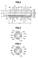
- the pressure sensors 13a, 13b, 13c, 13d are for detecting a contact pressure to occur when the distal end surface of tube body 12 contacts a lumen wall when the tube body 12 is inserted into the lumen. That is, the pressure sensors 13a, 13b, 13c, 13d are configured to have a shape and area to detect the pressure to occur when the distal end surface of the tube body 12 contacts the lumen wall or the like.
- the tube body 12 is provided with the first bending portion 14 configured with a length dimension L, and the second bending portion 15 which is provided in a linked manner to the first bending portion 14, having the same length dimension L as with the first bending portion 14.
- the bending portions 14, 15 are each provided with four bending mechanism portions at an interval of about 90 degrees, as shown in FIGS. 3 and 4 .
- the bending mechanism portions are what are known as artificial muscles 14a, 14b, 14c, 14d, 15a, 15b, 15c, 15d, serving as polymeric actuators.
- the first bending portion 14 includes the artificial muscles 14a, 14b, 14c, 14d
- the second bending portion 15 includes the artificial muscles 15a, 15b, 15c, 15d.
- the polymeric actuators are formed such that, when a voltage is applied thereto, positive ions in a polymeric electrolyte move to a cathode side, resulting in swelling of the front and rear lateral portions of the actuators and therefore bending and deformation thereof.
- the artificial muscles 14a, 14b, 14c, 14d, 15a, 15b, 15c, 15d are formed to have a predetermined width dimension h with the length L. Note that the pressure sensors 13a, 13b, 13c, 13d, the artificial muscles 14a, 14b, 14c, 14d, and the artificial muscles 15a, 15b, 15c, 15d are arranged at similar positions as viewed from the front, in other words, in the same phase in a cross sectional direction.
- the strain sensors 21a, 21b, 21c, 21d, 22a, 22b, 22c, 22d having a length dimension shorter than L.
- the strain sensors are bending shape measuring means, which measure bending state of the bending portions 14, 15 in bent state.
- a voltage is applied to each of the artificial muscle 14a and the artificial muscle 14c opposite to the artificial muscle 14a so as to bend the artificial muscles 14a, 14c in the same direction. That is, by adequately controlling a voltage to apply to each of the artificial muscles 14a, 14b, 14c, 14d of the first bending portion 14, the first bending portion 14 can be bent in up/down and left/right directions.
- the second bending portion 15 can also be similarly bent in up/down and left/right directions by adequately controlling a voltage to apply to each of the artificial muscles 15a, 15b, 15c, 15d.
- the strain sensors 21a, 21b, 21c, 21d detect strain that occurs with bending action of the artificial muscles 14a, 14b, 14c, 14d provided to the first bending portion 14.
- the strain sensors 22a, 22b, 22c, 22d detect strain that occurs with bending action of the artificial muscles 15a, 15b, 15c, 15d provided to the second bending portion 15. From the strain detected by these strain sensors 21a to 21d and 22a to 22d, respective curvatures of the bending portions 14, 15 are calculated by a calculation section 18a of the control unit 18 and recorded in a recording section 18d based on the calculation results.
- the signal cable 17 is extended. A proximal end of the signal cable 17 is connected to the control unit 18.
- electric wires 17a, 17b and signal lines 13e, 17c, 17d are contained.
- the electric wire 17a is connected to each of the artificial muscles 14a, 14b, 14c, 14d configuring the first bending portion 14.
- the electric wire 17b is connected to each of the artificial muscles 15a, 15b, 15c, 15d configuring the second bending portion 15.
- These electric wires 17a, 17b supply bending action voltage to activate the bending portions 14, 15 to bend.
- the signal line 13e is connected to each of the pressure sensors 13a, 13b, 13c, 13d.
- the signal line 13e transmits pressure detection signal detected by the pressure sensors 13a, 13b, 13c, 13d.
- the signal line 17c is connected to each of the strain sensors 21a, 21b, 21c, 21d, to transmit a detection value corresponding to the bending state.
- the signal line 17d is connected to each of the strain sensors 22a, 22b, 22c, 22d, to transmit a detection value corresponding to the bending state.
- the control unit 18, the joystick apparatus 19, and the foot switch 20 are operation portions of the treatment instrument apparatus for endoscope 20.
- the joystick apparatus 19 includes a first joystick 19a that outputs an instruction signal to operate to bend the first bending portion 14, and a joystick 19b that outputs an instruction signal to operate to bend the second bending portion 15. Based on difference in the direction of the inclining operation and inclining angle as the operation amount of the joysticks 19a, 19b, the control unit 18 generates a bending action voltage to control bending directions and curvatures of the first bending portion 14 or the second bending portion 15.
- the generated bending action voltage is then applied via the electric wires 17a, 17b to the artificial muscles 14a, 14b, 14c, 14d of the first bending portion 14, or the artificial muscles 15a, 15b, 15c, 15d of the second bending portion 115, to activate the bending portions 14, 15 to bend.
- the foot switch 20 outputs an instruction signal to activate the advancing/retreating apparatus 21 to rotate forward, and an instruction signal to activate the same to rotate backward.
- the control unit 18 When the first switch 20a is operated to turn on, the control unit 18 outputs to the electric motor of the advancing/retreating apparatus 21 a control signal to drive the electric motor to rotate forward, via the signal cable 18a. Then, when the second switch 20a is turned off, the electric motor stops driving.
- the control unit 18 outputs to the electric motor of the advancing/retreating apparatus 21 a control signal to drive the electric motor to rotate backward, via the signal cable 18a. Then, when the first switch 20a is brought into an off state, the electric motor stops driving.
- the control unit 18 includes an advance/retreat control section 18b as advance/retreat control means and a bend control section 18c as bend control means.
- the advance/retreat control section 18b generates a control signal based on the instruction signal from the foot switch 20, while at the same time generates a control signal based on measurement results outputted from the pressure sensors 13a, 13b, 13c, 13d, so as to activate the advancing/retreating apparatus 21 to advance/retreat the tube body 12.
- the advance/retreat control section 18b generates a bending action voltage based on the instruction signal outputted from the joysticks 19a, 19b of the joystick apparatus 19, while at the same time generates a bending action voltage in line with detection values corresponding to the bending state, outputted from the strain gauges 21a to 21d, 22a to 22d, so as to activate the corresponding bending portions 14, 15 to bend in a predetermined direction.
- the tube body 12 of the endoscopic treatment instrument 11 is inserted into the treatment instrument insertion duct 2d of the insertion portion 2 from the treatment instrument insertion port 6a of the operation portion 3 via the advancing/retreating apparatus 21 mounted at the treatment instrument insertion port 6 of the endoscope apparatus 1. Then, the distal end of the tube body 12 is protruded from the distal end portion 2a of the insertion portion 2. Thereafter, the treatment instrument raising table (not shown) provided to the distal end portion 2a is operated to raise so as to insert the tube body 12 into, for example, the bile duct via the papilla.
- the operator On confirming on the screen that the distal end of the tube body 12 is inserted into the bile duct, the operator operates to turn on the first switch 20a of the foot switch 20. This results in a control signal to be outputted from the control unit 18 to the advancing/retreating apparatus 21, to drive to rotate the electric motor, advancing the tube body 12 toward a deep part of the bile duct.
- control by the control unit 18 starts.
- the control unit 18 obtains pressure values detected by the pressure sensors 13a, 13b, 13c, 13d provided on the distal end surface of the tube body 12 as shown in step S1, then proceeding to step S2.
- step S2 by means of the calculation section 18a, the control unit 18 judges whether or not the pressure value obtained from each of the sensors 13a, 13b, 13c, 13d is equal to or smaller than a threshold value, that is, "pressure value of each pressure sensor ⁇ threshold value", while also judging whether or not the pressure values of the pressure sensors 13a, 13b, 13c, 13d are generally the same.
- the threshold value here is a value with a magnitude that prevents damage to the lumen wall. Therefore, even if the pressure value has reached the threshold value, the bile duct wall or the like is not damaged by advancing of the tube body 12 in contact with the lumen wall.
- step S2 when the tube body 12 is smoothly advancing in a straight part of the bile duct, the pressure sensors 13a, 13b, 13c, 13d provide pressure values that are generally the same and smaller than the threshold value.
- the pressure sensors 13a, 13b, 13c, 13d when the tube body 12 is advancing in a curving part of the bile duct, at least a part of the distal end surface of the tube body 12 contacts with the curving bile duct wall.
- the pressure sensor 13a in contact with the bile duct wall has a detected pressure value that is higher than detected pressure values of the other pressure sensors 13b, 13c, 13d.
- the control unit 18 causes the control unit 18 to judge that the side having the pressure sensor 13a on the distal end surface is in contact with the lumen wall.
- the control unit 18 thus compares the pressure values detected by the pressure sensors 13a, 13b, 13c, 13d to judge whether or not the distal end surface of the tube body 12 is in contact with the bile duct wall or the like.
- step S2 if the respective pressure values detected by the pressure sensors 13a, 13b, 13c, 13d are equal to or smaller than the threshold value, the control unit 18 judges that the distal end surface of the tube body 12 is not in contact with the bile duct wall, and proceeds to step S4.
- step S4 the control unit 18 outputs, from the advance/retreat control section 18b to the advancing/retreating apparatus 21, a control signal to drive to rotate forward the advancing/retreating apparatus 21, and obtains detection values of the strain sensors 21a, 21b, 21c, 21d provided to the first bending portion 14, to calculate a curvature Rn by means of the calculation section 18a.
- the output of the control signal to drive to rotate forward the advancing/retreating apparatus 21 makes the tube body 12 advance by ⁇ ln.
- the control unit 18 obtains a detection value of each of the strain sensors 21a, 21b, 21c, 21d provided in the first bending portion 14, so as to calculate the curvature Rn of the first bending portion 14 from the strain amount.
- step S5 the control unit 18 makes addition of ⁇ ln which is the advance amount of the tube body 12, and judges whether or not the resulting addition is equal to or smaller than the entire length L in the axial direction of the first bending portion 14.
- step S5 if the resulting addition of ⁇ ln is judged to be equal to or smaller than the entire length L of the first bending portion 14, the processing proceeds to step S1.
- step S3 the control unit 18 performs control to cause the screen to display position of, for example, the pressure sensor 13a that has detected a pressure equal to or greater than the threshold value; cause the screen to display a bending direction opposite to that of the position of the pressure sensor 13a; prompt an operation of the joystick 18a of the joystick apparatus 18; and apply a bending action voltage to the artificial muscles 14a, 14c to bend the first bending portion 14 in the direction opposite to that of the position of the pressure sensor 13a.
- the first bending portion 14 is to be bent by half a diameter d of the tube body 12 shown in FIG. 2 .
- the control unit 18 activates the first bending portion 14 to bend in the direction opposite to that of the setting position of, for example, the pressure sensor 13a that has detected a pressure greater than the threshold value in the step S3, and then returns to step S1 again.
- step S5 the control unit 18 judges, in the step S5, that a resulting addition value of the advance by ⁇ ln of the tube body 12 is equal to or greater than the entire length L of the first bending portion, then proceeds to step S6.
- step S6 the control unit 18 extracts from the recording section 18d data of the curvature Rn in the advancing by ⁇ ln of the first bending portion 14, thereafter continuing the advancing and insertion of the tube body 12.
- the bending operation of the joystick 19b of the joystick apparatus 19 is performed based on the data of the curvature Rn in the advancing by ⁇ ln of the first bending portion 14, extracted in the control unit 18.
- the second bending portion 15 is bend-controlled based on the data recorded in the recording section 18d by the control unit 18. This results in that the second bending portion 15 traces the path on which the first bending portion 14 advanced, which allows efficiently and smoothly performing the bending action of the second bending portion 15.
- the plurality of pressure sensors 13a, 13b, 13c, 13d are provided on the distal end surface of the tube body 12 to be inserted in the lumen, and in addition, the first bending portion 14 including the artificial muscles 14a, 14b, 14c, 14d adjacently provided in the axial direction of the tube body 12, and the second bending portion 15 including the artificial muscles 15a, 15b, 15c, 15d are respectively provided with the strain sensors 21a to 21d and the strain sensors 22a to 22d for detecting the respective curvatures of the bending portions 14, 15. Therefore, it is made possible to quickly and smoothly perform the insertion operation into the complicatedly bent lumen without damaging the lumen wall by the advance of the tube body 12.
- the artificial muscles 14a, 14c of the bending portion 14 and the artificial muscle 15a, 15c of the bending portions 15 are operated to be contract simultaneously. This allows the bending operation in the upward direction to be performed more quickly. Note that, also in other directions, similar working and effect can be obtained by simultaneouly operating the artificial muscles in the same phase.
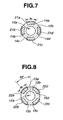
- the artificial muscle 15a, 15b, 15c, 15d provided to the second bending portion 15 and the strain sensors 22a, 22b, 22c, 22d provided on respective outer surfaces of the artificial muscle 15a, 15b, 15c, 15d, shown in FIG. 8 may be arranged in a manner shifted by, for example, 45 degrees, i.e., in a changed phase in a cross section.
- FIGS. 7 and 8 In the case of performing a bending operation in the same diagonal direction as above using the arrangement of the artificial muscles shown in FIGS. 3 and 4 , a total of four artificial muscles are controlled: the artificial muscles 14a, 14d of the first bending portion 14 and the artificial muscles 15a, 15d of the second bending portion 15. Therefore, the configuration in FIGS. 7 and 8 can better reduce the load on the control circuit provided in the control unit 18.
- the above embodiment of the present invention has described an exemplary configuration in which the first bending portion 14 and the second bending portion 15 are respectively provided with four artificial muscles 14a, 14b, 14c, 14d and 15a, 15b, 15c, 15d, at an interval of 90 degrees.
- the interval of providing the artificial muscles is not limited to 90 degrees, that is, four intervals.
- three artificial muscle may be provided at an interval of 120 degrees, or two artificial muscles may be provided at an interval of 180 degrees. That is, the artificial muscles may be arranged in any manner to allow the distal end part of the tube body 12 to bend in up/down direction or left/right direction.
- the bending mechanism portions of the first bending portion 14 and the second bending portion 15 employ artificial muscles, i.e., polymeric actuators.
- the bending mechanism is not limited to the artificial muscle, but may be one configured by a shape-memory alloy to perform a bending action, or actuators not needing cooling means such as an air pressure actuator to be activated to bend by air pressure, or a wire-driven actuator to be activated to bend by a pulling wire.
- the pressure sensors 13a, 13b, 13c, 13d may be arranged on a tapered surface of, for example, 45 degrees provided on the end surface of the tube body 12.
Landscapes
- Health & Medical Sciences (AREA)
- Life Sciences & Earth Sciences (AREA)
- Surgery (AREA)
- Engineering & Computer Science (AREA)
- General Health & Medical Sciences (AREA)
- Molecular Biology (AREA)
- Pathology (AREA)
- Veterinary Medicine (AREA)
- Public Health (AREA)
- Biophysics (AREA)
- Biomedical Technology (AREA)
- Heart & Thoracic Surgery (AREA)
- Medical Informatics (AREA)
- Physics & Mathematics (AREA)
- Animal Behavior & Ethology (AREA)
- Optics & Photonics (AREA)
- Nuclear Medicine, Radiotherapy & Molecular Imaging (AREA)
- Radiology & Medical Imaging (AREA)
- Human Computer Interaction (AREA)
- Endoscopes (AREA)
- Instruments For Viewing The Inside Of Hollow Bodies (AREA)
Applications Claiming Priority (2)
| Application Number | Priority Date | Filing Date | Title |
|---|---|---|---|
| JP2005174058 | 2005-06-14 | ||
| EP06757256A EP1892009B1 (fr) | 2005-06-14 | 2006-06-12 | Instrument de traitement à endoscope |
Related Parent Applications (1)
| Application Number | Title | Priority Date | Filing Date |
|---|---|---|---|
| EP06757256.0 Division | 2006-06-12 |
Publications (3)
| Publication Number | Publication Date |
|---|---|
| EP2289591A2 true EP2289591A2 (fr) | 2011-03-02 |
| EP2289591A8 EP2289591A8 (fr) | 2011-05-04 |
| EP2289591A3 EP2289591A3 (fr) | 2012-01-04 |
Family
ID=37532243
Family Applications (2)
| Application Number | Title | Priority Date | Filing Date |
|---|---|---|---|
| EP06757256A Not-in-force EP1892009B1 (fr) | 2005-06-14 | 2006-06-12 | Instrument de traitement à endoscope |
| EP10015160A Withdrawn EP2289591A3 (fr) | 2005-06-14 | 2006-06-12 | Instrument de traitement endoscope et appareil d'instrument de traitement pour endoscope |
Family Applications Before (1)
| Application Number | Title | Priority Date | Filing Date |
|---|---|---|---|
| EP06757256A Not-in-force EP1892009B1 (fr) | 2005-06-14 | 2006-06-12 | Instrument de traitement à endoscope |
Country Status (5)
| Country | Link |
|---|---|
| US (1) | US20080097159A1 (fr) |
| EP (2) | EP1892009B1 (fr) |
| JP (1) | JP5000503B2 (fr) |
| CN (1) | CN101198370B (fr) |
| WO (1) | WO2006134881A1 (fr) |
Families Citing this family (86)
| Publication number | Priority date | Publication date | Assignee | Title |
|---|---|---|---|---|
| US8882657B2 (en) | 2003-03-07 | 2014-11-11 | Intuitive Surgical Operations, Inc. | Instrument having radio frequency identification systems and methods for use |
| US20040199052A1 (en) | 2003-04-01 | 2004-10-07 | Scimed Life Systems, Inc. | Endoscopic imaging system |
| US11819192B2 (en) | 2004-03-23 | 2023-11-21 | Boston Scientific Scimed, Inc. | In-vivo visualization system |
| US7922654B2 (en) | 2004-08-09 | 2011-04-12 | Boston Scientific Scimed, Inc. | Fiber optic imaging catheter |
| JP4764417B2 (ja) | 2004-03-23 | 2011-09-07 | ボストン サイエンティフィック リミテッド | 生体内視覚化システム |
| US20060252993A1 (en) * | 2005-03-23 | 2006-11-09 | Freed David I | Medical devices and systems |
| EP1956962B1 (fr) | 2005-11-22 | 2020-09-16 | Intuitive Surgical Operations, Inc. | SYSTèME DE DéTERMINATION DE LA FORME D'UN INSTRUMENT PLIABLE |
| GB2435689B (en) * | 2006-03-02 | 2009-04-08 | Insensys Ltd | Structural monitoring |
| US8568299B2 (en) | 2006-05-19 | 2013-10-29 | Intuitive Surgical Operations, Inc. | Methods and apparatus for displaying three-dimensional orientation of a steerable distal tip of an endoscope |
| KR101422558B1 (ko) * | 2007-01-29 | 2014-07-24 | 인튜어티브 서지컬 인코포레이티드 | 형상 센서를 이용하여 기계를 제어하는 시스템 |
| US7655004B2 (en) | 2007-02-15 | 2010-02-02 | Ethicon Endo-Surgery, Inc. | Electroporation ablation apparatus, system, and method |
| US20080216840A1 (en) * | 2007-03-06 | 2008-09-11 | Searete Llc, A Limited Liability Corporation Of The State Of Delaware | Imaging via the airway |
| US8579897B2 (en) | 2007-11-21 | 2013-11-12 | Ethicon Endo-Surgery, Inc. | Bipolar forceps |
| US8568410B2 (en) | 2007-08-31 | 2013-10-29 | Ethicon Endo-Surgery, Inc. | Electrical ablation surgical instruments |
| US8262655B2 (en) | 2007-11-21 | 2012-09-11 | Ethicon Endo-Surgery, Inc. | Bipolar forceps |
| US9220398B2 (en) | 2007-10-11 | 2015-12-29 | Intuitive Surgical Operations, Inc. | System for managing Bowden cables in articulating instruments |
| US8480657B2 (en) * | 2007-10-31 | 2013-07-09 | Ethicon Endo-Surgery, Inc. | Detachable distal overtube section and methods for forming a sealable opening in the wall of an organ |
| US20090112059A1 (en) | 2007-10-31 | 2009-04-30 | Nobis Rudolph H | Apparatus and methods for closing a gastrotomy |
| US8182418B2 (en) | 2008-02-25 | 2012-05-22 | Intuitive Surgical Operations, Inc. | Systems and methods for articulating an elongate body |
| US8262680B2 (en) | 2008-03-10 | 2012-09-11 | Ethicon Endo-Surgery, Inc. | Anastomotic device |
| US8771260B2 (en) | 2008-05-30 | 2014-07-08 | Ethicon Endo-Surgery, Inc. | Actuating and articulating surgical device |
| US8679003B2 (en) | 2008-05-30 | 2014-03-25 | Ethicon Endo-Surgery, Inc. | Surgical device and endoscope including same |
| US8403926B2 (en) | 2008-06-05 | 2013-03-26 | Ethicon Endo-Surgery, Inc. | Manually articulating devices |
| US8361112B2 (en) | 2008-06-27 | 2013-01-29 | Ethicon Endo-Surgery, Inc. | Surgical suture arrangement |
| US8888792B2 (en) | 2008-07-14 | 2014-11-18 | Ethicon Endo-Surgery, Inc. | Tissue apposition clip application devices and methods |
| US8262563B2 (en) | 2008-07-14 | 2012-09-11 | Ethicon Endo-Surgery, Inc. | Endoscopic translumenal articulatable steerable overtube |
| US8211125B2 (en) * | 2008-08-15 | 2012-07-03 | Ethicon Endo-Surgery, Inc. | Sterile appliance delivery device for endoscopic procedures |
| US8529563B2 (en) | 2008-08-25 | 2013-09-10 | Ethicon Endo-Surgery, Inc. | Electrical ablation devices |
| US8241204B2 (en) | 2008-08-29 | 2012-08-14 | Ethicon Endo-Surgery, Inc. | Articulating end cap |
| US8480689B2 (en) * | 2008-09-02 | 2013-07-09 | Ethicon Endo-Surgery, Inc. | Suturing device |
| US8409200B2 (en) | 2008-09-03 | 2013-04-02 | Ethicon Endo-Surgery, Inc. | Surgical grasping device |
| DE102008047776B4 (de) * | 2008-09-17 | 2012-11-22 | Richard Wolf Gmbh | Endoskopisches Instrument |
| US8337394B2 (en) | 2008-10-01 | 2012-12-25 | Ethicon Endo-Surgery, Inc. | Overtube with expandable tip |
| US8157834B2 (en) | 2008-11-25 | 2012-04-17 | Ethicon Endo-Surgery, Inc. | Rotational coupling device for surgical instrument with flexible actuators |
| US8361066B2 (en) | 2009-01-12 | 2013-01-29 | Ethicon Endo-Surgery, Inc. | Electrical ablation devices |
| US9226772B2 (en) * | 2009-01-30 | 2016-01-05 | Ethicon Endo-Surgery, Inc. | Surgical device |
| US8252057B2 (en) | 2009-01-30 | 2012-08-28 | Ethicon Endo-Surgery, Inc. | Surgical access device |
| EP2459049B1 (fr) * | 2009-07-29 | 2019-08-28 | TransEnterix Surgical, Inc. | Ports pour instrument déviables |
| US8733099B2 (en) * | 2009-10-05 | 2014-05-27 | Massachusetts Institute Of Technology | Flexible actuator based on shape memory alloy sheet |
| US20110098704A1 (en) | 2009-10-28 | 2011-04-28 | Ethicon Endo-Surgery, Inc. | Electrical ablation devices |
| US8608652B2 (en) | 2009-11-05 | 2013-12-17 | Ethicon Endo-Surgery, Inc. | Vaginal entry surgical devices, kit, system, and method |
| US8496574B2 (en) | 2009-12-17 | 2013-07-30 | Ethicon Endo-Surgery, Inc. | Selectively positionable camera for surgical guide tube assembly |
| US8353487B2 (en) | 2009-12-17 | 2013-01-15 | Ethicon Endo-Surgery, Inc. | User interface support devices for endoscopic surgical instruments |
| US8506564B2 (en) | 2009-12-18 | 2013-08-13 | Ethicon Endo-Surgery, Inc. | Surgical instrument comprising an electrode |
| US9028483B2 (en) | 2009-12-18 | 2015-05-12 | Ethicon Endo-Surgery, Inc. | Surgical instrument comprising an electrode |
| US9005198B2 (en) | 2010-01-29 | 2015-04-14 | Ethicon Endo-Surgery, Inc. | Surgical instrument comprising an electrode |
| DE102010009003B4 (de) * | 2010-02-24 | 2014-05-15 | Richard Wolf Gmbh | Endoskopisches Instrument |
| US10092291B2 (en) | 2011-01-25 | 2018-10-09 | Ethicon Endo-Surgery, Inc. | Surgical instrument with selectively rigidizable features |
| US9254169B2 (en) | 2011-02-28 | 2016-02-09 | Ethicon Endo-Surgery, Inc. | Electrical ablation devices and methods |
| US9314620B2 (en) | 2011-02-28 | 2016-04-19 | Ethicon Endo-Surgery, Inc. | Electrical ablation devices and methods |
| US9233241B2 (en) | 2011-02-28 | 2016-01-12 | Ethicon Endo-Surgery, Inc. | Electrical ablation devices and methods |
| US9049987B2 (en) | 2011-03-17 | 2015-06-09 | Ethicon Endo-Surgery, Inc. | Hand held surgical device for manipulating an internal magnet assembly within a patient |
| EP2583616B1 (fr) * | 2011-03-29 | 2015-04-01 | Olympus Medical Systems Corp. | Endoscope |
| CN103153161B (zh) * | 2011-03-29 | 2015-12-02 | 奥林巴斯株式会社 | 内窥镜 |
| US9572481B2 (en) | 2011-05-13 | 2017-02-21 | Intuitive Surgical Operations, Inc. | Medical system with multiple operating modes for steering a medical instrument through linked body passages |
| JP5771488B2 (ja) * | 2011-09-14 | 2015-09-02 | オリンパス株式会社 | 内視鏡装置 |
| GB2497518A (en) * | 2011-12-08 | 2013-06-19 | Haemoband Surgical Ltd | Elongate probe with at least one bend sensor |
| US8986199B2 (en) | 2012-02-17 | 2015-03-24 | Ethicon Endo-Surgery, Inc. | Apparatus and methods for cleaning the lens of an endoscope |
| US10898064B2 (en) * | 2012-03-07 | 2021-01-26 | Transenterix Europe S.A.R.L. | Endoscopic control and maneuvering system in at least two degrees of freedom |
| US9427255B2 (en) | 2012-05-14 | 2016-08-30 | Ethicon Endo-Surgery, Inc. | Apparatus for introducing a steerable camera assembly into a patient |
| JP2013252387A (ja) * | 2012-06-08 | 2013-12-19 | Canon Inc | 医療用画像処理装置 |
| US11278182B2 (en) | 2012-06-28 | 2022-03-22 | Koninklijke Philips N.V. | Enhanced visualization of blood vessels using a robotically steered endoscope |
| US9078662B2 (en) | 2012-07-03 | 2015-07-14 | Ethicon Endo-Surgery, Inc. | Endoscopic cap electrode and method for using the same |
| US9545290B2 (en) | 2012-07-30 | 2017-01-17 | Ethicon Endo-Surgery, Inc. | Needle probe guide |
| US9572623B2 (en) | 2012-08-02 | 2017-02-21 | Ethicon Endo-Surgery, Inc. | Reusable electrode and disposable sheath |
| US10314649B2 (en) | 2012-08-02 | 2019-06-11 | Ethicon Endo-Surgery, Inc. | Flexible expandable electrode and method of intraluminal delivery of pulsed power |
| US9277957B2 (en) | 2012-08-15 | 2016-03-08 | Ethicon Endo-Surgery, Inc. | Electrosurgical devices and methods |
| CN104704543A (zh) * | 2012-10-01 | 2015-06-10 | 皇家飞利浦有限公司 | 使用设备形状感测的临床决策支持和训练系统 |
| WO2014110219A2 (fr) * | 2013-01-09 | 2014-07-17 | Inspectron, Inc. | Dispositif de téléinspection |
| JP6045377B2 (ja) * | 2013-02-06 | 2016-12-14 | オリンパス株式会社 | 湾曲装置 |
| US9289582B2 (en) | 2013-02-25 | 2016-03-22 | Terumo Kabushiki Kaisha | Methods for treating sinus ostia using balloon catheter devices having a bendable balloon portion |
| US10098527B2 (en) | 2013-02-27 | 2018-10-16 | Ethidcon Endo-Surgery, Inc. | System for performing a minimally invasive surgical procedure |
| US9345864B2 (en) | 2013-03-15 | 2016-05-24 | Terumo Kabushiki Kaisha | Methods for treating sinus ostia using balloon catheter devices having a slidable balloon portion |
| WO2015026557A1 (fr) | 2013-08-20 | 2015-02-26 | Cook Medical Technologies Llc | Dispositif de visualisation et manche pouvant être montés sur un endoscope |
| WO2016053754A1 (fr) | 2014-09-29 | 2016-04-07 | Cook Medical Technologies Llc | Mécanisme de fixation de poignée à libération/raccord rapide de dispositif de visualisation pouvant être monté sur un endoscope |
| CN104367313A (zh) * | 2014-11-13 | 2015-02-25 | 余月 | 一种经皮肾镜手术术中实时测压装置 |
| KR20160085202A (ko) * | 2015-01-07 | 2016-07-15 | 삼성전자주식회사 | 디스플레이장치 |
| JP2016140407A (ja) * | 2015-01-30 | 2016-08-08 | 国立研究開発法人産業技術総合研究所 | カテーテルシステム |
| JP6601732B2 (ja) * | 2016-01-29 | 2019-11-06 | 国立大学法人鳥取大学 | 内視鏡用センサシステム |
| JP6293396B1 (ja) * | 2016-05-26 | 2018-03-14 | オリンパス株式会社 | 制御装置 |
| US20190142247A1 (en) * | 2016-05-26 | 2019-05-16 | Makeway Llc | Endoscope and Treatment Tool Drive Module |
| WO2018057633A1 (fr) * | 2016-09-21 | 2018-03-29 | Intuitive Surgical Operations, Inc. | Systèmes et procédés de détection du flambement d'un instrument |
| KR102391591B1 (ko) * | 2017-05-16 | 2022-04-27 | 박연호 | 가요성 연성부 형태 추정 장치 및 이를 포함하는 내시경 시스템 |
| GB2567491B (en) * | 2017-10-16 | 2020-03-25 | Haemoband Surgical Ltd | Medical probe insertion system |
| DE102019101089A1 (de) * | 2019-01-16 | 2020-07-16 | Vizaar Industrial Imaging Ag | Aktuator für eine endoskopische Sonde, endoskopische Sonde und Verfahren zur Steuerung eines Aktuators einer endoskopischen Sonde |
| CN111528768B (zh) * | 2020-04-13 | 2022-12-06 | 珠海明象医用科技有限公司 | 一种电致形变弯曲的内窥镜 |
Citations (2)
| Publication number | Priority date | Publication date | Assignee | Title |
|---|---|---|---|---|
| JPH0663004A (ja) | 1992-01-14 | 1994-03-08 | Olympus Optical Co Ltd | 医療用チューブ |
| JP2005174058A (ja) | 2003-12-12 | 2005-06-30 | Matsushita Electric Ind Co Ltd | 家庭内情報システム |
Family Cites Families (15)
| Publication number | Priority date | Publication date | Assignee | Title |
|---|---|---|---|---|
| US4469091A (en) * | 1980-08-28 | 1984-09-04 | Slanetz Jr Charles A | Tactile control device for a remote sensing device |
| DE3707787A1 (de) * | 1987-03-11 | 1988-09-22 | Patrik Dr Med Gruendler | Endoskop |
| IT1235460B (it) * | 1987-07-31 | 1992-07-30 | Confida Spa | Endoscopio flessibile. |
| JPH084629B2 (ja) * | 1987-10-05 | 1996-01-24 | テルモ株式会社 | カテーテル |
| US4982725A (en) * | 1989-07-04 | 1991-01-08 | Olympus Optical Co., Ltd. | Endoscope apparatus |
| US5060632A (en) * | 1989-09-05 | 1991-10-29 | Olympus Optical Co., Ltd. | Endoscope apparatus |
| JP3135134B2 (ja) * | 1991-04-19 | 2001-02-13 | オリンパス光学工業株式会社 | 可撓管の湾曲装置 |
| JPH05184526A (ja) * | 1991-09-17 | 1993-07-27 | Olympus Optical Co Ltd | 可撓管の湾曲機構 |
| US5386741A (en) * | 1993-06-07 | 1995-02-07 | Rennex; Brian G. | Robotic snake |
| IL127017A (en) * | 1996-05-17 | 2003-07-06 | Biosense Inc | Self-aligning catheter |
| JP3752328B2 (ja) * | 1996-11-06 | 2006-03-08 | オリンパス株式会社 | 内視鏡装置 |
| US6610007B2 (en) * | 2000-04-03 | 2003-08-26 | Neoguide Systems, Inc. | Steerable segmented endoscope and method of insertion |
| DE60121316T2 (de) * | 2000-04-21 | 2007-08-02 | Université Pierre et Marie Curie (Paris VI) | Vorrichtung zur positionierung, untersuchung und/oder behandlung, insbesondere im gebiet der endoskopie und/oder minimal invasiver chirurgie |
| JP3600194B2 (ja) * | 2000-10-02 | 2004-12-08 | オリンパス株式会社 | 内視鏡 |
| US6770027B2 (en) * | 2001-10-05 | 2004-08-03 | Scimed Life Systems, Inc. | Robotic endoscope with wireless interface |
-
2006
- 2006-06-12 WO PCT/JP2006/311771 patent/WO2006134881A1/fr active Application Filing
- 2006-06-12 CN CN2006800211970A patent/CN101198370B/zh not_active Expired - Fee Related
- 2006-06-12 EP EP06757256A patent/EP1892009B1/fr not_active Not-in-force
- 2006-06-12 JP JP2007521281A patent/JP5000503B2/ja not_active Expired - Fee Related
- 2006-06-12 EP EP10015160A patent/EP2289591A3/fr not_active Withdrawn
-
2007
- 2007-12-10 US US11/953,377 patent/US20080097159A1/en not_active Abandoned
Patent Citations (2)
| Publication number | Priority date | Publication date | Assignee | Title |
|---|---|---|---|---|
| JPH0663004A (ja) | 1992-01-14 | 1994-03-08 | Olympus Optical Co Ltd | 医療用チューブ |
| JP2005174058A (ja) | 2003-12-12 | 2005-06-30 | Matsushita Electric Ind Co Ltd | 家庭内情報システム |
Also Published As
| Publication number | Publication date |
|---|---|
| EP1892009B1 (fr) | 2011-12-21 |
| US20080097159A1 (en) | 2008-04-24 |
| EP2289591A8 (fr) | 2011-05-04 |
| JPWO2006134881A1 (ja) | 2009-01-08 |
| EP2289591A3 (fr) | 2012-01-04 |
| CN101198370B (zh) | 2011-02-02 |
| EP1892009A1 (fr) | 2008-02-27 |
| CN101198370A (zh) | 2008-06-11 |
| WO2006134881A1 (fr) | 2006-12-21 |
| JP5000503B2 (ja) | 2012-08-15 |
| EP1892009A4 (fr) | 2009-05-27 |
Similar Documents
| Publication | Publication Date | Title |
|---|---|---|
| EP1892009B1 (fr) | Instrument de traitement à endoscope | |
| JP5336760B2 (ja) | 内視鏡システム | |
| US8187169B2 (en) | Medical apparatus | |
| JP5301867B2 (ja) | 医療用マニピュレータシステム | |
| JP5384869B2 (ja) | 内視鏡処置システム | |
| EP2052691B1 (fr) | Dispositif médical | |
| EP1769722B1 (fr) | Système endoscopique avec un endoscope et un instrument médical raccordé à l'endoscope | |
| JP6177488B2 (ja) | マニピュレータ及び医療システム | |
| JP2015016181A (ja) | 手術支援ロボット | |
| JP2007307241A (ja) | 回転自走式内視鏡、及び回転自走式内視鏡装置 | |
| US9603507B2 (en) | Insertion device | |
| CN113350653A (zh) | 一种多功能导管 | |
| JPH078447A (ja) | 内視鏡の自動挿入装置 | |
| JPH06285009A (ja) | 可撓性管状挿入具の湾曲装置 | |
| JP4813630B2 (ja) | 内視鏡装置 | |
| JP5102074B2 (ja) | 内視鏡 | |
| CN212214357U (zh) | 一种多功能导管 | |
| JP4766959B2 (ja) | 内視鏡用挿入補助具 | |
| JP2010035587A (ja) | 内視鏡、内視鏡システム及び内視鏡の湾曲部矯正方法 | |
| WO2022201110A1 (fr) | Endoscope télescopique à continuum à armature flexible et son procédé de fonctionnement | |
| JPWO2015159719A1 (ja) | 内視鏡 | |
| JP2002336191A (ja) | 電動湾曲式内視鏡 |
Legal Events
| Date | Code | Title | Description |
|---|---|---|---|
| PUAI | Public reference made under article 153(3) epc to a published international application that has entered the european phase |
Free format text: ORIGINAL CODE: 0009012 |
|
| 17P | Request for examination filed |
Effective date: 20101130 |
|
| AC | Divisional application: reference to earlier application |
Ref document number: 1892009 Country of ref document: EP Kind code of ref document: P |
|
| AK | Designated contracting states |
Kind code of ref document: A2 Designated state(s): DE FR GB |
|
| RAP1 | Party data changed (applicant data changed or rights of an application transferred) |
Owner name: OLYMPUS MEDICAL SYSTEMS CORP. |
|
| PUAL | Search report despatched |
Free format text: ORIGINAL CODE: 0009013 |
|
| AK | Designated contracting states |
Kind code of ref document: A3 Designated state(s): DE FR GB |
|
| RIC1 | Information provided on ipc code assigned before grant |
Ipc: A61B 5/03 20060101ALI20111129BHEP Ipc: A61B 1/00 20060101ALI20111129BHEP Ipc: A61B 1/005 20060101ALI20111129BHEP Ipc: A61M 25/01 20060101AFI20111129BHEP |
|
| 17Q | First examination report despatched |
Effective date: 20121009 |
|
| RAP1 | Party data changed (applicant data changed or rights of an application transferred) |
Owner name: OLYMPUS CORPORATION |
|
| RAP1 | Party data changed (applicant data changed or rights of an application transferred) |
Owner name: OLYMPUS CORPORATION |
|
| RAP1 | Party data changed (applicant data changed or rights of an application transferred) |
Owner name: OLYMPUS CORPORATION |
|
| STAA | Information on the status of an ep patent application or granted ep patent |
Free format text: STATUS: THE APPLICATION IS DEEMED TO BE WITHDRAWN |
|
| 18D | Application deemed to be withdrawn |
Effective date: 20160607 |