EP2288880B1 - Staudrucksonde mit differenzdruckerhöher - Google Patents
Staudrucksonde mit differenzdruckerhöher Download PDFInfo
- Publication number
- EP2288880B1 EP2288880B1 EP08773266A EP08773266A EP2288880B1 EP 2288880 B1 EP2288880 B1 EP 2288880B1 EP 08773266 A EP08773266 A EP 08773266A EP 08773266 A EP08773266 A EP 08773266A EP 2288880 B1 EP2288880 B1 EP 2288880B1
- Authority
- EP
- European Patent Office
- Prior art keywords
- flow
- probe
- differential pressure
- encompasses
- pressure
- Prior art date
- Legal status (The legal status is an assumption and is not a legal conclusion. Google has not performed a legal analysis and makes no representation as to the accuracy of the status listed.)
- Active
Links
- 239000000523 sample Substances 0.000 title claims description 44
- 239000000126 substance Substances 0.000 claims description 11
- 230000000694 effects Effects 0.000 claims description 5
- 239000012530 fluid Substances 0.000 claims description 5
- 239000002105 nanoparticle Substances 0.000 claims description 2
- 230000003116 impacting effect Effects 0.000 claims 1
- 230000004888 barrier function Effects 0.000 description 5
- 239000012535 impurity Substances 0.000 description 2
- 238000005259 measurement Methods 0.000 description 2
- 238000009825 accumulation Methods 0.000 description 1
- 230000005484 gravity Effects 0.000 description 1
- 239000002245 particle Substances 0.000 description 1
- 239000005871 repellent Substances 0.000 description 1
Images


Classifications
-
- G—PHYSICS
- G01—MEASURING; TESTING
- G01F—MEASURING VOLUME, VOLUME FLOW, MASS FLOW OR LIQUID LEVEL; METERING BY VOLUME
- G01F1/00—Measuring the volume flow or mass flow of fluid or fluent solid material wherein the fluid passes through a meter in a continuous flow
- G01F1/05—Measuring the volume flow or mass flow of fluid or fluent solid material wherein the fluid passes through a meter in a continuous flow by using mechanical effects
- G01F1/34—Measuring the volume flow or mass flow of fluid or fluent solid material wherein the fluid passes through a meter in a continuous flow by using mechanical effects by measuring pressure or differential pressure
- G01F1/36—Measuring the volume flow or mass flow of fluid or fluent solid material wherein the fluid passes through a meter in a continuous flow by using mechanical effects by measuring pressure or differential pressure the pressure or differential pressure being created by the use of flow constriction
- G01F1/40—Details of construction of the flow constriction devices
- G01F1/46—Pitot tubes
-
- G—PHYSICS
- G01—MEASURING; TESTING
- G01F—MEASURING VOLUME, VOLUME FLOW, MASS FLOW OR LIQUID LEVEL; METERING BY VOLUME
- G01F1/00—Measuring the volume flow or mass flow of fluid or fluent solid material wherein the fluid passes through a meter in a continuous flow
- G01F1/72—Devices for measuring pulsing fluid flows
-
- G—PHYSICS
- G01—MEASURING; TESTING
- G01F—MEASURING VOLUME, VOLUME FLOW, MASS FLOW OR LIQUID LEVEL; METERING BY VOLUME
- G01F15/00—Details of, or accessories for, apparatus of groups G01F1/00 - G01F13/00 insofar as such details or appliances are not adapted to particular types of such apparatus
- G01F15/12—Cleaning arrangements; Filters
Definitions
- the invention relates to a dynamic pressure probe, by which the back pressure of a flowing, interspersed with foreign matter medium is measured.
- a pitot tube is known in which the ends of the measuring channels lie inside the pitot tube and are covered by a slot.
- the slot breaks through a contact surface of the probe laterally and over the entire width. The lateral openings of the slot on the probe cause, due to the flow flowing around the probe, that the fluid infiltrated with foreign substances enters the slot at the contact surface and is sucked out laterally therefrom.
- the GB 21, 864 shows a probe in the form of an elongated shaped pin with a smooth surface whose narrow ends are aligned in or against the flow.
- the ends have central slots which open at the base of the probe in each case into a measuring channel
- the DE 14 73 126 A1 shows measuring channels in an elliptical shaped probe, which are aligned perpendicular to the flow.
- the US 6,802,225 B2 shows a probe whose measuring channels open in a return aligned parallel to the flow.
- the invention adopts the knowledge that the foreign substances have a very low inertia and therefore follow the flow directly, a behavior which is known in the art as particle tracking behavior.
- the probe has been designed in an inventive manner such that the flow direction in the near field of the differential pressure booster does not run perpendicular to the storage surface.
- the probe according to the invention has a differential pressure booster of particular design with an oblique run-on surface according to claim 1, which meets the flow and is deflected.
- the deflection vector resulting from this deflection of the flow in the near field of the differential pressure booster is composed of a proportion perpendicular to the storage area and a proportion tangent to the storage area.
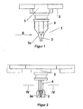
- the side view of the probe 1 in FIG. 1 is selected transversely to the flow direction S.
- the probe 1 can be fastened by means of fastening elements 2 to a pipe, not shown here, in such a way that the storage surface 3a of the differential pressure booster 3 points in the direction of the flow S.
- the contact surface 3a of the differential pressure booster 3 has a ramp-like course. In the area of the contact surface 3 is not visible in this view opening. This opening is the end of a channel which extends through an extension 4 upwards in the head 5 of the probe 1.
- differential pressure booster 3 Due to the effect of the differential pressure booster 3 is a function of the flow S, a differential pressure between the two openings of the holes.
- the probe 1 is constructed approximately symmetrically in the region of the differential pressure booster 3 on the side facing the flow S and on the side facing away from the flow.
- This symmetrical structure has the advantage that with the probe 1, a flow can be measured, no matter from which direction the flow comes. It is therefore also very well possible with this probe 1 to measure flows that pulsate with changing direction in a tube.
- the extension 4 is chosen so that the differential pressure booster 3 and thus the contact surface 3 a are in a region of the tube in which no edge effects of the pipe wall are more present.
- the extension 4 may be configured differently long depending on the tort the probe 1.
- the extension 4 in turn is designed so that it has low flow resistance.
- the flow S does not impinge perpendicularly but obliquely on the contact surface 3a and is thereby deflected.
- the directional vector of the flow is composed of a portion tangential to the contact surface 3a and a portion which continues in the direction of the original flow S.
- This straight part enters the opening.
- FIG. 2 shows the off FIG. 1 considered known situation in the flow direction.
- the contact surface 3 can now be seen the opening which leads over the channel 6 in the extension 4 to the head 5 of the probe 1.
- the cylindrical bore of the channel 6 results in an oval opening.
- the hatched area is the inner wall 6 a of the channel 6.
- This inner wall 6a is set back relative to the contact surface 3a. Foreign substances, which are located in the flowing medium hardly have the opportunity to get to the set-back inner wall 6a, because the flow portion of the tangential to the contact surface 3a flows acts as a barrier for these foreign substances.
- the impurities have a low mass and do not bring with them the kinetic energy that would be necessary to break through this flow barrier and then reach the inner wall 6a.
- the probe 1 is preferably installed so that the openings point downwards, whereby the gravity acting on the foreign bodies and the tangential to the Run-on surface 3 a running flow force act in an approximately same direction. This makes it even less likely that a foreign body reaches the wall 6a.
- the narrow front edge 4a of the extension 4 can be seen.
- the extension 4 has a flow-optimized cross-section with a flow-facing tip portion 4a. Subsequently, the cross-section expands to provide sufficient space for the holes and towards the side facing away from the flow, the cross section tapers again to a pointed end part.
- section line IV-IV refers to the illustration in FIG. 4 .
- FIG. 3 shows a view from below of the probe 1. In this view, the symmetrical structure can be seen.
- the contact surface 3a of the differential pressure booster 3 is wider than the extension 4. From the extension 4, the pointed front part 4a and also pointed end part 4b is visible.
- the channel 7 is located.
- the angle with which the outer surfaces meet on the front part 4a is about 22 degrees, the angle at which the outer surfaces 4b terminate at the end part is also about 22 degrees.
- FIG. 4 shows a section along the line IV-IV in FIG. 2 ,
- the cross section of the extension 4 is only slightly thicker than the bore hole width of the channels 6 and 7. This advantageously achieves that the probe 1 offers a low flow resistance and only in the region of the probe in which a flow resistance for the function of the probe is necessary , the back pressure caused by the differential pressure booster occurs.
- FIG. 5 shows a further embodiment of the invention.
- the view is selected in the direction of flow.
- the ramp-like contact surface 3a of the differential pressure booster 3 is made wider. This results in a larger tangential to the contact surface 3a extending flow component.
- this tangentially extending flow fraction acts as a barrier for impurities entrained in the flow.
- a stronger flow is now also a stronger barrier, which is then again suitable to keep foreign matter with higher kinetic energy.
- FIG. 6 shows a side view of the probe 1 with the flow lines S.
- a portion S1 of the flow S is deflected and runs as a flow S1 substantially tangentially to the contact surface 3a.
- the deflected portion S1 of the flow meets the undeflected flow S at an angle substantially equal to the inclination angle of the thrust face 3a.
- the undeflected flow S provides resistance to the deflected portion S1 of the flow.
- the dimensioning of the contact surface is tunable to the particular application.
- a small contact surface is necessary.
- a small contact surface has the advantage of lower flow resistance.
- a larger contact surface will always be used if the advantageous property of a stronger barrier effect is desired in order to reject even larger foreign substances.
- the surface of the probe with a foreign substance-repellent layer, for example nanoparticles. Should one or the other foreign body then reach the wall 6a, the risk of this foreign substance sticking to the probe is reduced.
- a foreign substance-repellent layer for example nanoparticles. Should one or the other foreign body then reach the wall 6a, the risk of this foreign substance sticking to the probe is reduced.
- the invention is industrially applicable in the field of flow measurement.
Landscapes
- Physics & Mathematics (AREA)
- Fluid Mechanics (AREA)
- General Physics & Mathematics (AREA)
- Measuring Volume Flow (AREA)
- Measuring Fluid Pressure (AREA)
Description
- Die Erfindung betrifft eine Staudrucksonde, durch welche der Staudruck eines strömenden, mit Fremdstoffen durchsetzten Mediums gemessen wird.
- Aus der
WO2007/009409 ist eine Staudrucksonde mit einem strömungsmechanischen Differenzdruckerhöher bekannt, welche aufgrund konstruktiver Ausgestaltung in gewissem Masse bereits unempfindlich ist gegenüber in der Strömung mitgeführten Fremdstoffen. - Aus dem
DE 23 56 725 ist eine Staudrucksonde bekannt, bei der die Enden der Messkanäle im Inneren der Staudrucksonde liegen und von einem Schlitz verdeckt sind. Der Schlitz durchbricht eine Anlauffläche der Sonde seitlich und über die gesamte Breite. Die seitlichen Öffnungen des Schlitzes an der Sonde bewirken aufgrund der die Sonde umfließenden Strömung, dass das mit Fremdstoffen durchsetzte Fluid an der Anlauffläche in den Schlitz eintritt und von dort seitlich wieder herausgesogen wird. - Das
GB 21, 864 - Das
DE 14 73 126 A1 zeigt Messkanäle in einer elliptisch geformten Sonde, die senkrecht zur Strömung ausgerichtet sind. - Das
US 6,802,225 B2 zeigt eine Sonde, deren Messkanäle in einem parallel zur Strömung ausgerichteten Rücksprung münden. - Es hat sich gezeigt, dass beim Einsatz der bekannten Staudrucksonde in stärker mit Fremdstoffen durchsetzten Medien, sich diese Fremdstoffe unter Umstanden dennoch im Bereich der Staufläche am Differenzdruckerhöher ansammeln können.
- Es ist Aufgabe der Erfindung, eine Staudrucksonde, welche nach dem Prinzip des Staudruckerhöhers arbeitet zu schaffen, wobei diese Staudrucksonde noch unempfindlicher gegenüber in der Strömung mitgeführten Fremdstoffen ist.
- Die Erfindung macht sich die Erkenntnis zu eigen, dass die Fremdstoffe eine sehr geringe Trägheit aufweisen und daher der Strömung direkt folgen, ein Verhalten, welche in der Fachwelt unter dem Begriff Partikelfolgeverhalten bekannt ist.
- Unter Anwendung dieser Erkenntnis wurde in erfinderischer Weise die Sonde so ausgestaltet, dass die Strömungsrichtung im Nahfeld des Differenzdruckerhöhers nicht senkrecht zur Staufläche verläuft.
- Die erfindungsgemäße Sonde hat einen Differenzdruckerhöher besonderer Ausgestaltung mit einer schrägen Anlauffläche gemäß Anspruch 1, auf welche die Strömung trifft und abgelenkt wird.
- Der durch diese Ablenkung resultierende Richtungsvektor der Strömung im Nahfeld des Differenzdruckerhöher setzt sich zusammen aus einem Anteil senkrecht zur Staufläche und einem Anteil tangential zur Staufläche.
- Der tangential verlaufende Anteil bewirkt, dass Fremdstoffe, welche stets der Strömung folgen an der Staufläche des Differenzdruckerhöhers vorbeigeführt werden. Eine Gefahr von Ablagerungen wird hierdurch vorteilhaft reduziert. Kurze Beschreibung der Zeichnungen
- Die Erfindung wird anhand von mehreren Figuren näher erläutert, es zeigen:
- Figur 1
- die Staudrucksonde in Seitenansicht, quer zur Strömung,
- Figur 2
- die Staudrucksonde in Seitenansicht, längs zur Strömung
- Figur 3
- die Staudrucksonde von unten betrachtet,
- Figur 4
- einen Schnitt durch die Staudrucksonde gemäß
Figur 2 - Figur 5
- eine weitere Ausgestaltung der Staudrucksonde
- Figur 6
- den Strömungsverlauf an der Staudrucksonde im Detail
- Die Seitenansicht der Sonde 1 in
Figur 1 ist quer zur Strömungsrichtung S gewählt. Die Sonde 1 ist über Befestigungselemente 2 an einem hier nicht gezeichneten Rohr so befestigbar, dass die Staufläche 3a des Differenzdruckerhöhers 3 in Richtung der Strömung S zeigt. - Die Anlauffläche 3a des Differenzdruckerhöhers 3 hat einen rampenartigen Verlauf. Im Bereich der Anlauffläche 3 befindet sich eine in dieser Darstellung nicht sichtbare Öffnung. Diese Öffnung ist das Ende eines Kanals, der durch eine Verlängerung 4 nach oben in den Kopf 5 der Sonde 1 verläuft.
- Auf der von der Strömung abgewandten Seite des Differenzdröckerhöhers 3 befindet sich ebenfalls eine Fläche, in der ebenfalls eine Öffnung und Bohrung vorhanden ist, die bis in den Kopf 5 der Sonde 1 führt. Die strömungsabgewandte Seite des Differenzdruckerhöhers ist in dieser Darstellung nicht sichtbar, Details hierzu sind in der
Figur 3 zu sehen. - Durch die Wirkung des Differenzdruckerhöhers 3 entsteht in Abhängigkeit von der Strömung S ein Differenzdruck zwischen den beiden Öffnungen der Bohrungen.
- Die Sonde 1 ist im Bereich des Differenzdruckerhöhers 3 auf der zur Strömung S zeigenden Seite und auf der von der Strömung abgewandten Seite in etwa symmetrisch aufgebaut.
- Dieser symmetrische Aufbau hat den Vorteil, dass mit der Sonde 1 eine Strömung gemessen werden kann, egal aus welcher Richtung die Strömung kommt. Es ist mit dieser Sonde 1 daher auch sehr gut möglich Strömungen zu messen, die mit wechselnder Richtung in einem Rohr pulsieren.
- Ebenso ist es natürlich auch möglich, den Aufbau asymmetrisch zu gestalten. Durch die asymmetrische Gestaltung ist es möglich die Anlauffläche optimiert für eine bevorzugte Strömungsrichtung zu gestalten.
- Im Kopf 5 der Sonde 1 können auch Drucksensoren untergebracht sein, ebenso ist es möglich, vom Kopf 5 aus über Leitungen eine Verbindung zu Drucksensoren herzustellen.
- Die Verlängerung 4 ist so gewählt, dass sich der Differenzdruckerhöher 3 und damit die Anlauffläche 3 a in einem Bereich des Rohres befinden, in welchem keine Randeffekte der Rohrwandung mehr vorhanden sind. Die Verlängerung 4 kann je nach Einsatztort der Sonde 1 unterschiedlich lang ausgestaltet sein.
- Die Verlängerung 4 ihrerseits ist so ausgestaltet, dass sie geringen Strömungswiderstand aufweist.
- Die Strömung S trifft nicht senkrecht sondern schräg auf die Anlauffläche 3a und wird hierdurch abgelenkt. Im Bereich der Öffnung zu dem Kanal 6 setzt sich der Richtungsvektor der Strömung zusammen aus einem Anteil tangential zur Anlauffläche 3a und einem Anteil, der weiter in Richtung der ursprünglichen Strömung S verläuft.
- Dieser gerade verlaufende Anteil tritt in die Öffnung ein.
- Die
Figur 2 zeigt die ausFigur 1 bekannte Situation in Strömungsrichtung betrachtet. In der Anlauffläche 3 erkennt man nun die Öffnung, welche über den Kanal 6 in der Verlängerung 4 zum Kopf 5 der Sonde 1 führt. - Aufgrund des schrägen Verlaufes der Anlauffläche 3 ergibt die zylindrische Bohrung des Kanals 6 eine ovale Öffnung. Der schraffiert dargestellte Bereich ist die Innenwand 6a des Kanals 6.
- Diese Innenwand 6a ist bezogen auf die Anlauffläche 3 a zurückversetzt. Fremdstoffe, welche sich im strömenden Medium befinden haben kaum die Möglichkeit bis an die zurückversetzte Innenwand 6a zu gelangen, denn der Strömungsanteil der tangential zur Anlauffläche 3a strömt wirkt wie eine Barriere für diese Fremdstoffe.
- Die Fremdstoffe haben eine geringe Masse und bringen nicht die kinetische Energie mit, die notwendig wäre, um diese Strömungsbarriere zu durchbrechen um dann auf die Innenwand 6a zu gelangen.
- Die Sonde 1 ist bevorzugt so eingebaut, dass die Öffnungen nach unten zeigen, wodurch die auf die Fremdkörper wirkende Schwerkraft und die tangential zur Anlauffläche 3 a verlaufende Strömungskraft in eine annähernd gleiche Richtung wirken. Hierdurch ist es noch unwahrscheinlicher, dass ein Fremdkörber bis an die Wandung 6a gelangt.
- In der Ansicht nach
Figur 2 ist die schmale Vorderkante 4a der Verlängerung 4 zu sehen. Die Verlängerung 4 hat einen strömungsoptimierten Querschnitt mit einem der Strömung zugewandten spitzen Vorderteil 4a. Anschließend weitet sich der Querschnitt, um ausreichend Platz für die Bohrungen zu bieten und zur strömungsabgewandten Seite hin verjüngt sich der Querschnitt wieder zu einem spitzen Endteil. - Die Schnittlinie IV-IV bezieht sich auf die Darstellung in
Figur 4 . - Die
Figur 3 zeigt einen Blick von unten auf die Sonde 1. In dieser Ansicht ist der symmetrische Aufbau erkennbar. Die Anlauffläche 3a des Differenzdruckerhöhers 3 ist breiter als die Verlängerung 4. Von der Verlängerung 4 ist das spitze Vorderteil 4a und das ebenfalls spitze Endteil 4b sichtbar. - Auf der strömungsabgewandten Seite des Differenzdruckerhöhers 3 befindet sich der Kanal 7.
- Der Bereich der Verlängerung 4, in welchem die Kanäle 6 und 7 verlaufen ist in dieser Ansicht durch die Anlauffläche 3 und die Unterdruckseite 3a des Differenzdruckerhöhers 3 verdeckt.
- Der Winkel mit dem die Aussenflächen am Vorderteil 4a zusammentreffen beträgt ca. 22 Grad, der Winkel mit dem die Außenflächen 4b am Endteil auslaufen beträgt ebenfalls etwa 22 Grad.
- Die
Figur 4 zeigt einen Schnitt entlang der Linie IV-IV inFigur 2 . Der Querschnitt der Verlängerung 4 ist nur unwesentlich dicker als die Bohrlochweite der Kanäle 6 und 7. Hierdurch wird vorteilhaft erreicht, dass die Sonde 1 einen geringen Strömungswiderstand bietet und nur in dem Bereich der Sonde, in welchem ein Strömungswiderstand für die Funktion der Sonde notwendig ist, tritt der durch den Differenzdruckerhöher hervorgerufene Staudruck auf. - Die
Figur 5 zeigt eine weitere Ausgestaltung der Erfindung. Die Ansicht ist in Strömungsrichtung gewählt. Bei dieser Ausführung ist die rampenartige Anlauffläche 3a des Differenzdruckerhöhers 3 breiter gestaltet. Hierdurch ergibt sich ein größerer tangential zur Anlauffläche 3a verlaufender Strömungsanteil. - Wie bereits weiter oben beschrieben wirkt dieser tangential verlaufende Strömungsanteil als Barriere für in der Strömung mitgeführte Fremdstoffe. Eine stärkere Strömung stellt nun auch eine stärkere Barriere dar, die dann wieder geeignet ist, Fremdstoffe mit höherer kinetischer Energie abzuhalten.
- Die
Figur 6 zeigt eine Seitenansicht der Sonde 1 mit den Strömungslinien S. - Durch die Anlauffläche 3a wird ein Teil S1 der Strömung S abgelenkt und verläuft als Strömung S1 im wesentlichen tangential zur Anlauffläche 3a. Der abgelenkte Teil S1 der Strömung trifft in einem Winkel, der im wesentlichen dem Neigungswinkel der Anlauffläche 3a entspricht auf die nicht abgelenkte Strömung S. Die nicht abgelenkte Strömung S bietet dem abgelenkten Anteil S1 der Strömung einen Widerstand.
- Die Folge ist eine Verminderung der lokalen Strömungsgeschwindigkeit und die Erhöhung des örtlichen Druckes im Bereich 3b. In diesem Bereich 3b befindet sich die Öffnung des Kanals 6.
- Diese erfinderische Ausgestaltung der Anlauffläche 3a und das dadurch erreichte, den örtlichen Druck erhöhende Strömungsverhalten im Bereich 3b trägt zur gesamten Wirkung des Differenzdruckerhöhers 3 bei.
- Die Dimensionierung der Anlauffläche ist so auf den jeweiligen Anwendungsfall abstimmbar. Bei Messungen in einem Medium, das nur kleine Fremdstoffe mitführt ist eine kleine Anlauffläche notwendig. Eine kleine Anlauffläche hat den Vorteil eines geringeren Strömungswiderstandes.
- Eine größere Anlauffläche wird immer dann zum Einsatz kommen, wenn die vorteilhafte Eigenschaft einer stärkeren Barrierewirkung gewünscht wird, um auch größere Fremdstoffe abzuweisen.
- Zusätzlich zu den auf Strömungsmechanik basierenden Maßnahmen ist es optional möglich, die Oberfläche der Sonde mit einer Fremdstoffe abweisenden Schicht, etwa sogenannten Nanoteilen auszustatten. Sollte dann doch der eine oder andere Fremdkörper die Wand 6a erreichen, so ist die Gefahr verringert, dass dieser Fremdstoff an der Sonde haften bleibt.
- Die Erfindung ist gewerblich anwendbar im Bereich der Strömungsmessung.
Claims (6)
- Staudrucksonde mit zwei Kanälen, die voneinander separiert sind und mit Ihrem einen Ende zu einem Druckmessfühler führen, einem strömungsmechanischen Differenzdruckerhöher (3) und einer Öffnung am jeweils anderen Ende jedes Kanals (6, 7), wobei die Öffnungen an verschiedenen Orten angeordnet sind, zwischen denen ein durch die Wirkung des Differenzdruckerhöhers (3) erzeugter, höherer Wert für den Differenzdruck auftritt, als der Wert des dynamischen Drucks des strömenden Fluids ist, wobei der strömungsmechanische Differenzdruckerhöher (3) eine bezogen auf die Strömungsrichtung des zu messenden Fluids schräge Anlauffläche (3a) aufweist und wobei sich das andere Ende eines der Kanäle (6) in der schrägen Anlauffläche (3a) befindet,
dadurch gekennzeichnet, dass
die Staudrucksonde (1) eine Verlängerung (4) aufweist, in welcher die vom Differenzdruckerhöher (3) ausgehenden Kanäle (6, 7) verlaufen, und dass die Anlauffläche (3a) breiter ist als die Verlängerung (4), so dass die Verlängerung (4) einen gegenüber dem Differenzdruckerhöher (3) verringerten Strömungswiderstand aufweist. - Staudrucksonde nach Anspruch 1
dadurch gekennzeichnet, dass
die Verlängerung (4) an ihrer strömungszugewandten Seite ein spitzes Vorderteil (4a) und an ihrer strömungsabgewandten Seite ein spitzes Endteil (4b) aufweist. - Staudrucksonde nach Anspruch 1 oder 2
dadurch gekennzeichnet, dass
die Anlauffläche (3a) die auftreffende Anteil der Strömung (S1) ablenkt und der abgelenkte Anteil der Strömung (S1) im wesentlichen tangential zur Oberfläche der Anlauffläche (3a) verläuft. - Staudrucksonde nach einem der vorangegangenen Ansprüche
dadurch gekennzeichnet, dass
die abgelenkte Strömung (S1) etwa im Bereich (3b) der Öffnung des Kanals (6) auf die nicht abgelenkte Strömung (S) trifft. - Staudrucksonde nach einem der vorangegangenen Ansprüche
dadurch gekennzeichnet, dass
die Sonde (1) eine Fremdstoffe abweisende Oberfläche aufweist. - Staudrucksonde nach einem der vorangegangenen Ansprüche
dadurch gekennzeichnet, dass
die Sonde (1) eine Oberfläche aus Nanopartikeln aufweist.
Applications Claiming Priority (1)
| Application Number | Priority Date | Filing Date | Title |
|---|---|---|---|
| PCT/DE2008/000986 WO2009152787A1 (de) | 2008-06-18 | 2008-06-18 | Staudrucksonde mit differenzdruckerhöher |
Publications (2)
| Publication Number | Publication Date |
|---|---|
| EP2288880A1 EP2288880A1 (de) | 2011-03-02 |
| EP2288880B1 true EP2288880B1 (de) | 2012-10-17 |
Family
ID=40173317
Family Applications (1)
| Application Number | Title | Priority Date | Filing Date |
|---|---|---|---|
| EP08773266A Active EP2288880B1 (de) | 2008-06-18 | 2008-06-18 | Staudrucksonde mit differenzdruckerhöher |
Country Status (3)
| Country | Link |
|---|---|
| EP (1) | EP2288880B1 (de) |
| DE (1) | DE112008003987A5 (de) |
| WO (1) | WO2009152787A1 (de) |
Families Citing this family (1)
| Publication number | Priority date | Publication date | Assignee | Title |
|---|---|---|---|---|
| CN102384771B (zh) * | 2011-11-24 | 2013-02-27 | 王忠辉 | 一种毕托巴流量传感器取压头 |
Family Cites Families (5)
| Publication number | Priority date | Publication date | Assignee | Title |
|---|---|---|---|---|
| GB191221864A (en) * | 1912-09-25 | 1913-08-07 | British Thomson Houston Co Ltd | Improvements in and relating to Nozzle Plugs for Fluid Flow Meters. |
| DE1473126B2 (de) * | 1963-03-14 | 1972-05-18 | Metrawatt GmbH, 8500 Nürnberg | Wirkdruckgeber zum messen der stroemungsgeschwindigkeit von fluessigkeiten |
| WO2004008961A1 (en) * | 2002-07-24 | 2004-01-29 | Versamed Medical Systems Ltd. | Respiratory flow sensor |
| WO2007009409A1 (de) * | 2005-07-14 | 2007-01-25 | Systec Controls Mess- Und Regelungstechnik Gmbh | Staudrucksonde |
| DE202007005695U1 (de) * | 2007-04-18 | 2008-08-28 | systec Controls Meß- und Regeltechnik GmbH | Staudrucksonde |
-
2008
- 2008-06-18 EP EP08773266A patent/EP2288880B1/de active Active
- 2008-06-18 DE DE112008003987T patent/DE112008003987A5/de active Pending
- 2008-06-18 WO PCT/DE2008/000986 patent/WO2009152787A1/de active Application Filing
Also Published As
| Publication number | Publication date |
|---|---|
| WO2009152787A1 (de) | 2009-12-23 |
| DE112008003987A5 (de) | 2011-06-09 |
| EP2288880A1 (de) | 2011-03-02 |
Similar Documents
| Publication | Publication Date | Title |
|---|---|---|
| EP0046965B1 (de) | Verfahren und Vorrichtung zur dynamischen und dichteunabhängigen Bestimmung des Massenstroms | |
| EP0198197B1 (de) | Differentialdruckströmungssonde | |
| EP1904812B1 (de) | Staudrucksonde | |
| DE102012224049A1 (de) | Sensorvorrichtung zur Erfassung mindestens einer Strömungseigenschaft eines fluiden Mediums | |
| DE10124997C2 (de) | Strömungsraten-Messvorrichtung | |
| DE102013009347A1 (de) | Durchflussmesser | |
| DE102005019613A1 (de) | Luftstromratenmessvorrichtung mit Messeinheit | |
| DE102015008146A1 (de) | Durchflusszähler | |
| DE2164180C3 (de) | Strömungsmesser | |
| DE102008042807B4 (de) | Vorrichtung zur Bestimmung eines Parameters eines strömenden fluiden Mediums | |
| DE1803018A1 (de) | Druckbegrenzungsventil | |
| WO2001018498A9 (de) | Vorrichtung zur messung von zumindest einem parameter eines in einer leitung strömenden mediums | |
| DE3714344C2 (de) | ||
| EP2288880B1 (de) | Staudrucksonde mit differenzdruckerhöher | |
| WO2019057621A1 (de) | Gas-durchflusssensor für eine beatmungsvorrichtung mit verminderter störanfälligkeit gegenüber feuchtigkeit im sensorgehäuse | |
| DE102009021324A1 (de) | Durchflussratenmesseinrichtung | |
| DE202007005695U1 (de) | Staudrucksonde | |
| EP1423663B1 (de) | Korrosionsbeständiger wirbelströmungsaufnehmer | |
| EP0407948B2 (de) | Flügelradzähler zum Messen einer Flüssigkeitsmenge | |
| DE3940474C1 (de) | ||
| DE102005001171B4 (de) | Vorrichtung zur Überwachung und/oder Messung des Durchflusses eines strömenden Fluids | |
| DE19648591C1 (de) | Wirkdruckgeber eines Durchflußmessers | |
| DE2437864C3 (de) | Strömungsmessvorrichtung | |
| DE4207043A1 (de) | Messwertaufnehmer | |
| EP2216637B1 (de) | Messrohr für eine Vorrichtung zur Abtastung eines Strömungsmittels |
Legal Events
| Date | Code | Title | Description |
|---|---|---|---|
| PUAI | Public reference made under article 153(3) epc to a published international application that has entered the european phase |
Free format text: ORIGINAL CODE: 0009012 |
|
| 17P | Request for examination filed |
Effective date: 20101209 |
|
| AK | Designated contracting states |
Kind code of ref document: A1 Designated state(s): AT BE BG CH CY CZ DE DK EE ES FI FR GB GR HR HU IE IS IT LI LT LU LV MC MT NL NO PL PT RO SE SI SK TR |
|
| AX | Request for extension of the european patent |
Extension state: AL BA MK RS |
|
| DAX | Request for extension of the european patent (deleted) | ||
| 17Q | First examination report despatched |
Effective date: 20120111 |
|
| GRAP | Despatch of communication of intention to grant a patent |
Free format text: ORIGINAL CODE: EPIDOSNIGR1 |
|
| GRAS | Grant fee paid |
Free format text: ORIGINAL CODE: EPIDOSNIGR3 |
|
| GRAA | (expected) grant |
Free format text: ORIGINAL CODE: 0009210 |
|
| AK | Designated contracting states |
Kind code of ref document: B1 Designated state(s): AT BE BG CH CY CZ DE DK EE ES FI FR GB GR HR HU IE IS IT LI LT LU LV MC MT NL NO PL PT RO SE SI SK TR |
|
| REG | Reference to a national code |
Ref country code: GB Ref legal event code: FG4D Free format text: NOT ENGLISH |
|
| REG | Reference to a national code |
Ref country code: CH Ref legal event code: EP |
|
| REG | Reference to a national code |
Ref country code: IE Ref legal event code: FG4D Free format text: LANGUAGE OF EP DOCUMENT: GERMAN |
|
| REG | Reference to a national code |
Ref country code: AT Ref legal event code: REF Ref document number: 580111 Country of ref document: AT Kind code of ref document: T Effective date: 20121115 |
|
| REG | Reference to a national code |
Ref country code: DE Ref legal event code: R096 Ref document number: 502008008427 Country of ref document: DE Effective date: 20121213 |
|
| REG | Reference to a national code |
Ref country code: NL Ref legal event code: VDEP Effective date: 20121017 |
|
| REG | Reference to a national code |
Ref country code: LT Ref legal event code: MG4D |
|
| PG25 | Lapsed in a contracting state [announced via postgrant information from national office to epo] |
Ref country code: ES Free format text: LAPSE BECAUSE OF FAILURE TO SUBMIT A TRANSLATION OF THE DESCRIPTION OR TO PAY THE FEE WITHIN THE PRESCRIBED TIME-LIMIT Effective date: 20130128 Ref country code: NL Free format text: LAPSE BECAUSE OF FAILURE TO SUBMIT A TRANSLATION OF THE DESCRIPTION OR TO PAY THE FEE WITHIN THE PRESCRIBED TIME-LIMIT Effective date: 20121017 Ref country code: HR Free format text: LAPSE BECAUSE OF FAILURE TO SUBMIT A TRANSLATION OF THE DESCRIPTION OR TO PAY THE FEE WITHIN THE PRESCRIBED TIME-LIMIT Effective date: 20121017 Ref country code: FI Free format text: LAPSE BECAUSE OF FAILURE TO SUBMIT A TRANSLATION OF THE DESCRIPTION OR TO PAY THE FEE WITHIN THE PRESCRIBED TIME-LIMIT Effective date: 20121017 Ref country code: IS Free format text: LAPSE BECAUSE OF FAILURE TO SUBMIT A TRANSLATION OF THE DESCRIPTION OR TO PAY THE FEE WITHIN THE PRESCRIBED TIME-LIMIT Effective date: 20130217 Ref country code: SE Free format text: LAPSE BECAUSE OF FAILURE TO SUBMIT A TRANSLATION OF THE DESCRIPTION OR TO PAY THE FEE WITHIN THE PRESCRIBED TIME-LIMIT Effective date: 20121017 Ref country code: LT Free format text: LAPSE BECAUSE OF FAILURE TO SUBMIT A TRANSLATION OF THE DESCRIPTION OR TO PAY THE FEE WITHIN THE PRESCRIBED TIME-LIMIT Effective date: 20121017 Ref country code: NO Free format text: LAPSE BECAUSE OF FAILURE TO SUBMIT A TRANSLATION OF THE DESCRIPTION OR TO PAY THE FEE WITHIN THE PRESCRIBED TIME-LIMIT Effective date: 20130117 |
|
| PG25 | Lapsed in a contracting state [announced via postgrant information from national office to epo] |
Ref country code: GR Free format text: LAPSE BECAUSE OF FAILURE TO SUBMIT A TRANSLATION OF THE DESCRIPTION OR TO PAY THE FEE WITHIN THE PRESCRIBED TIME-LIMIT Effective date: 20130118 Ref country code: PL Free format text: LAPSE BECAUSE OF FAILURE TO SUBMIT A TRANSLATION OF THE DESCRIPTION OR TO PAY THE FEE WITHIN THE PRESCRIBED TIME-LIMIT Effective date: 20121017 Ref country code: PT Free format text: LAPSE BECAUSE OF FAILURE TO SUBMIT A TRANSLATION OF THE DESCRIPTION OR TO PAY THE FEE WITHIN THE PRESCRIBED TIME-LIMIT Effective date: 20130218 Ref country code: LV Free format text: LAPSE BECAUSE OF FAILURE TO SUBMIT A TRANSLATION OF THE DESCRIPTION OR TO PAY THE FEE WITHIN THE PRESCRIBED TIME-LIMIT Effective date: 20121017 Ref country code: SI Free format text: LAPSE BECAUSE OF FAILURE TO SUBMIT A TRANSLATION OF THE DESCRIPTION OR TO PAY THE FEE WITHIN THE PRESCRIBED TIME-LIMIT Effective date: 20121017 |
|
| PG25 | Lapsed in a contracting state [announced via postgrant information from national office to epo] |
Ref country code: EE Free format text: LAPSE BECAUSE OF FAILURE TO SUBMIT A TRANSLATION OF THE DESCRIPTION OR TO PAY THE FEE WITHIN THE PRESCRIBED TIME-LIMIT Effective date: 20121017 Ref country code: BG Free format text: LAPSE BECAUSE OF FAILURE TO SUBMIT A TRANSLATION OF THE DESCRIPTION OR TO PAY THE FEE WITHIN THE PRESCRIBED TIME-LIMIT Effective date: 20130117 Ref country code: DK Free format text: LAPSE BECAUSE OF FAILURE TO SUBMIT A TRANSLATION OF THE DESCRIPTION OR TO PAY THE FEE WITHIN THE PRESCRIBED TIME-LIMIT Effective date: 20121017 Ref country code: CZ Free format text: LAPSE BECAUSE OF FAILURE TO SUBMIT A TRANSLATION OF THE DESCRIPTION OR TO PAY THE FEE WITHIN THE PRESCRIBED TIME-LIMIT Effective date: 20121017 Ref country code: SK Free format text: LAPSE BECAUSE OF FAILURE TO SUBMIT A TRANSLATION OF THE DESCRIPTION OR TO PAY THE FEE WITHIN THE PRESCRIBED TIME-LIMIT Effective date: 20121017 |
|
| PLBE | No opposition filed within time limit |
Free format text: ORIGINAL CODE: 0009261 |
|
| STAA | Information on the status of an ep patent application or granted ep patent |
Free format text: STATUS: NO OPPOSITION FILED WITHIN TIME LIMIT |
|
| PG25 | Lapsed in a contracting state [announced via postgrant information from national office to epo] |
Ref country code: RO Free format text: LAPSE BECAUSE OF FAILURE TO SUBMIT A TRANSLATION OF THE DESCRIPTION OR TO PAY THE FEE WITHIN THE PRESCRIBED TIME-LIMIT Effective date: 20121017 Ref country code: IT Free format text: LAPSE BECAUSE OF FAILURE TO SUBMIT A TRANSLATION OF THE DESCRIPTION OR TO PAY THE FEE WITHIN THE PRESCRIBED TIME-LIMIT Effective date: 20121017 |
|
| 26N | No opposition filed |
Effective date: 20130718 |
|
| REG | Reference to a national code |
Ref country code: DE Ref legal event code: R097 Ref document number: 502008008427 Country of ref document: DE Effective date: 20130718 |
|
| PG25 | Lapsed in a contracting state [announced via postgrant information from national office to epo] |
Ref country code: CY Free format text: LAPSE BECAUSE OF FAILURE TO SUBMIT A TRANSLATION OF THE DESCRIPTION OR TO PAY THE FEE WITHIN THE PRESCRIBED TIME-LIMIT Effective date: 20121017 |
|
| BERE | Be: lapsed |
Owner name: SYSTEC CONTROLS MESS- UND REGELTECHNIK G.M.B.H. Effective date: 20130630 |
|
| PG25 | Lapsed in a contracting state [announced via postgrant information from national office to epo] |
Ref country code: MC Free format text: LAPSE BECAUSE OF FAILURE TO SUBMIT A TRANSLATION OF THE DESCRIPTION OR TO PAY THE FEE WITHIN THE PRESCRIBED TIME-LIMIT Effective date: 20121017 |
|
| REG | Reference to a national code |
Ref country code: IE Ref legal event code: MM4A |
|
| PG25 | Lapsed in a contracting state [announced via postgrant information from national office to epo] |
Ref country code: BE Free format text: LAPSE BECAUSE OF NON-PAYMENT OF DUE FEES Effective date: 20130630 |
|
| PG25 | Lapsed in a contracting state [announced via postgrant information from national office to epo] |
Ref country code: IE Free format text: LAPSE BECAUSE OF NON-PAYMENT OF DUE FEES Effective date: 20130618 |
|
| REG | Reference to a national code |
Ref country code: AT Ref legal event code: MM01 Ref document number: 580111 Country of ref document: AT Kind code of ref document: T Effective date: 20130618 |
|
| PG25 | Lapsed in a contracting state [announced via postgrant information from national office to epo] |
Ref country code: AT Free format text: LAPSE BECAUSE OF NON-PAYMENT OF DUE FEES Effective date: 20130618 |
|
| PG25 | Lapsed in a contracting state [announced via postgrant information from national office to epo] |
Ref country code: MT Free format text: LAPSE BECAUSE OF FAILURE TO SUBMIT A TRANSLATION OF THE DESCRIPTION OR TO PAY THE FEE WITHIN THE PRESCRIBED TIME-LIMIT Effective date: 20121017 |
|
| PG25 | Lapsed in a contracting state [announced via postgrant information from national office to epo] |
Ref country code: TR Free format text: LAPSE BECAUSE OF FAILURE TO SUBMIT A TRANSLATION OF THE DESCRIPTION OR TO PAY THE FEE WITHIN THE PRESCRIBED TIME-LIMIT Effective date: 20121017 |
|
| PG25 | Lapsed in a contracting state [announced via postgrant information from national office to epo] |
Ref country code: LU Free format text: LAPSE BECAUSE OF NON-PAYMENT OF DUE FEES Effective date: 20130618 Ref country code: HU Free format text: LAPSE BECAUSE OF FAILURE TO SUBMIT A TRANSLATION OF THE DESCRIPTION OR TO PAY THE FEE WITHIN THE PRESCRIBED TIME-LIMIT; INVALID AB INITIO Effective date: 20080618 |
|
| REG | Reference to a national code |
Ref country code: FR Ref legal event code: PLFP Year of fee payment: 9 |
|
| REG | Reference to a national code |
Ref country code: FR Ref legal event code: PLFP Year of fee payment: 10 |
|
| REG | Reference to a national code |
Ref country code: FR Ref legal event code: PLFP Year of fee payment: 11 |
|
| PGFP | Annual fee paid to national office [announced via postgrant information from national office to epo] |
Ref country code: FR Payment date: 20180625 Year of fee payment: 11 |
|
| PGFP | Annual fee paid to national office [announced via postgrant information from national office to epo] |
Ref country code: GB Payment date: 20180626 Year of fee payment: 11 |
|
| GBPC | Gb: european patent ceased through non-payment of renewal fee |
Effective date: 20190618 |
|
| PG25 | Lapsed in a contracting state [announced via postgrant information from national office to epo] |
Ref country code: GB Free format text: LAPSE BECAUSE OF NON-PAYMENT OF DUE FEES Effective date: 20190618 |
|
| PG25 | Lapsed in a contracting state [announced via postgrant information from national office to epo] |
Ref country code: FR Free format text: LAPSE BECAUSE OF NON-PAYMENT OF DUE FEES Effective date: 20190630 |
|
| REG | Reference to a national code |
Ref country code: DE Ref legal event code: R081 Ref document number: 502008008427 Country of ref document: DE Owner name: SYSTEC AUTOMOTIVE GMBH, DE Free format text: FORMER OWNER: SYSTEC CONTROLS MESS- UND REGELTECHNIK GMBH, 82178 PUCHHEIM, DE |
|
| PGFP | Annual fee paid to national office [announced via postgrant information from national office to epo] |
Ref country code: DE Payment date: 20230629 Year of fee payment: 16 |
|
| PGFP | Annual fee paid to national office [announced via postgrant information from national office to epo] |
Ref country code: CH Payment date: 20230702 Year of fee payment: 16 |
|
| P01 | Opt-out of the competence of the unified patent court (upc) registered |
Effective date: 20231229 |