EP2287471B1 - Gebläsevorrichtung der CPAP/NIPPV-Art - Google Patents
Gebläsevorrichtung der CPAP/NIPPV-Art Download PDFInfo
- Publication number
- EP2287471B1 EP2287471B1 EP10182132A EP10182132A EP2287471B1 EP 2287471 B1 EP2287471 B1 EP 2287471B1 EP 10182132 A EP10182132 A EP 10182132A EP 10182132 A EP10182132 A EP 10182132A EP 2287471 B1 EP2287471 B1 EP 2287471B1
- Authority
- EP
- European Patent Office
- Prior art keywords
- cpap
- impeller
- gas
- impellers
- blower
- Prior art date
- Legal status (The legal status is an assumption and is not a legal conclusion. Google has not performed a legal analysis and makes no representation as to the accuracy of the status listed.)
- Expired - Lifetime
Links
- 239000012530 fluid Substances 0.000 claims abstract description 8
- 238000004891 communication Methods 0.000 claims abstract description 7
- 238000009423 ventilation Methods 0.000 claims abstract description 7
- XAGFODPZIPBFFR-UHFFFAOYSA-N aluminium Chemical compound [Al] XAGFODPZIPBFFR-UHFFFAOYSA-N 0.000 claims description 10
- 229910052782 aluminium Inorganic materials 0.000 claims description 9
- 229920001971 elastomer Polymers 0.000 claims description 5
- 230000003434 inspiratory effect Effects 0.000 claims description 5
- 229920001821 foam rubber Polymers 0.000 claims description 3
- 229920001296 polysiloxane Polymers 0.000 claims description 3
- 230000000241 respiratory effect Effects 0.000 claims description 3
- 230000029058 respiratory gaseous exchange Effects 0.000 claims description 3
- 239000005060 rubber Substances 0.000 claims description 3
- 239000000806 elastomer Substances 0.000 claims description 2
- 229920002635 polyurethane Polymers 0.000 claims description 2
- 239000004814 polyurethane Substances 0.000 claims description 2
- 239000007789 gas Substances 0.000 description 32
- 238000013016 damping Methods 0.000 description 9
- 239000000463 material Substances 0.000 description 7
- 230000005534 acoustic noise Effects 0.000 description 6
- 238000000034 method Methods 0.000 description 6
- 238000005495 investment casting Methods 0.000 description 5
- 229910052751 metal Inorganic materials 0.000 description 5
- 239000002184 metal Substances 0.000 description 5
- QVGXLLKOCUKJST-UHFFFAOYSA-N atomic oxygen Chemical compound [O] QVGXLLKOCUKJST-UHFFFAOYSA-N 0.000 description 3
- 238000002347 injection Methods 0.000 description 3
- 239000007924 injection Substances 0.000 description 3
- 238000004519 manufacturing process Methods 0.000 description 3
- 208000001797 obstructive sleep apnea Diseases 0.000 description 3
- 229910052760 oxygen Inorganic materials 0.000 description 3
- 239000001301 oxygen Substances 0.000 description 3
- 230000007704 transition Effects 0.000 description 3
- 230000003519 ventilatory effect Effects 0.000 description 3
- MYMOFIZGZYHOMD-UHFFFAOYSA-N Dioxygen Chemical compound O=O MYMOFIZGZYHOMD-UHFFFAOYSA-N 0.000 description 2
- 230000009286 beneficial effect Effects 0.000 description 2
- 229910001882 dioxygen Inorganic materials 0.000 description 2
- 230000000694 effects Effects 0.000 description 2
- 150000002739 metals Chemical class 0.000 description 2
- 208000023504 respiratory system disease Diseases 0.000 description 2
- 238000007493 shaping process Methods 0.000 description 2
- 238000009987 spinning Methods 0.000 description 2
- 229910000838 Al alloy Inorganic materials 0.000 description 1
- 241000258957 Asteroidea Species 0.000 description 1
- 206010014561 Emphysema Diseases 0.000 description 1
- 229920000106 Liquid crystal polymer Polymers 0.000 description 1
- 239000004977 Liquid-crystal polymers (LCPs) Substances 0.000 description 1
- 229910000861 Mg alloy Inorganic materials 0.000 description 1
- 229910000831 Steel Inorganic materials 0.000 description 1
- 230000001133 acceleration Effects 0.000 description 1
- 239000000853 adhesive Substances 0.000 description 1
- 230000001070 adhesive effect Effects 0.000 description 1
- 238000005452 bending Methods 0.000 description 1
- 238000005266 casting Methods 0.000 description 1
- 238000004590 computer program Methods 0.000 description 1
- 238000005094 computer simulation Methods 0.000 description 1
- 239000004020 conductor Substances 0.000 description 1
- 238000005516 engineering process Methods 0.000 description 1
- 238000001595 flow curve Methods 0.000 description 1
- 230000020169 heat generation Effects 0.000 description 1
- JEIPFZHSYJVQDO-UHFFFAOYSA-N iron(III) oxide Inorganic materials O=[Fe]O[Fe]=O JEIPFZHSYJVQDO-UHFFFAOYSA-N 0.000 description 1
- 238000005259 measurement Methods 0.000 description 1
- 230000003647 oxidation Effects 0.000 description 1
- 238000007254 oxidation reaction Methods 0.000 description 1
- 239000004033 plastic Substances 0.000 description 1
- 229920003023 plastic Polymers 0.000 description 1
- 230000004044 response Effects 0.000 description 1
- 238000004088 simulation Methods 0.000 description 1
- 239000010959 steel Substances 0.000 description 1
- 238000010408 sweeping Methods 0.000 description 1
- 238000004804 winding Methods 0.000 description 1
Images


Classifications
-
- A—HUMAN NECESSITIES
- A61—MEDICAL OR VETERINARY SCIENCE; HYGIENE
- A61M—DEVICES FOR INTRODUCING MEDIA INTO, OR ONTO, THE BODY; DEVICES FOR TRANSDUCING BODY MEDIA OR FOR TAKING MEDIA FROM THE BODY; DEVICES FOR PRODUCING OR ENDING SLEEP OR STUPOR
- A61M16/00—Devices for influencing the respiratory system of patients by gas treatment, e.g. mouth-to-mouth respiration; Tracheal tubes
- A61M16/0057—Pumps therefor
- A61M16/0066—Blowers or centrifugal pumps
- A61M16/0069—Blowers or centrifugal pumps the speed thereof being controlled by respiratory parameters, e.g. by inhalation
-
- F—MECHANICAL ENGINEERING; LIGHTING; HEATING; WEAPONS; BLASTING
- F04—POSITIVE - DISPLACEMENT MACHINES FOR LIQUIDS; PUMPS FOR LIQUIDS OR ELASTIC FLUIDS
- F04D—NON-POSITIVE-DISPLACEMENT PUMPS
- F04D17/00—Radial-flow pumps, e.g. centrifugal pumps; Helico-centrifugal pumps
- F04D17/08—Centrifugal pumps
- F04D17/16—Centrifugal pumps for displacing without appreciable compression
- F04D17/164—Multi-stage fans, e.g. for vacuum cleaners
-
- F—MECHANICAL ENGINEERING; LIGHTING; HEATING; WEAPONS; BLASTING
- F04—POSITIVE - DISPLACEMENT MACHINES FOR LIQUIDS; PUMPS FOR LIQUIDS OR ELASTIC FLUIDS
- F04D—NON-POSITIVE-DISPLACEMENT PUMPS
- F04D25/00—Pumping installations or systems
- F04D25/02—Units comprising pumps and their driving means
- F04D25/08—Units comprising pumps and their driving means the working fluid being air, e.g. for ventilation
- F04D25/084—Units comprising pumps and their driving means the working fluid being air, e.g. for ventilation hand fans
-
- F—MECHANICAL ENGINEERING; LIGHTING; HEATING; WEAPONS; BLASTING
- F04—POSITIVE - DISPLACEMENT MACHINES FOR LIQUIDS; PUMPS FOR LIQUIDS OR ELASTIC FLUIDS
- F04D—NON-POSITIVE-DISPLACEMENT PUMPS
- F04D25/00—Pumping installations or systems
- F04D25/16—Combinations of two or more pumps ; Producing two or more separate gas flows
- F04D25/166—Combinations of two or more pumps ; Producing two or more separate gas flows using fans
-
- A—HUMAN NECESSITIES
- A61—MEDICAL OR VETERINARY SCIENCE; HYGIENE
- A61M—DEVICES FOR INTRODUCING MEDIA INTO, OR ONTO, THE BODY; DEVICES FOR TRANSDUCING BODY MEDIA OR FOR TAKING MEDIA FROM THE BODY; DEVICES FOR PRODUCING OR ENDING SLEEP OR STUPOR
- A61M2205/00—General characteristics of the apparatus
- A61M2205/42—Reducing noise
Definitions
- the present invention relates to an apparatus for supplying breathable gas to a human, used in, for example, Continuous Positive Airway Pressure (CPAP) treatment of Obstructive Sleep Apnea (OSA), other respiratory diseases and disorders such as emphysema, or the application of assisted ventilation.
- CPAP Continuous Positive Airway Pressure
- OSA Obstructive Sleep Apnea
- assisted ventilation a respiratory system for supplying breathable gas to a human, used in, for example, Continuous Positive Airway Pressure (CPAP) treatment of Obstructive Sleep Apnea (OSA), other respiratory diseases and disorders such as emphysema, or the application of assisted ventilation.
- CPAP Continuous Positive Airway Pressure
- OSA Obstructive Sleep Apnea
- assisted ventilation emphysema
- CPAP treatment of OSA involves the delivery of a pressurized breathable gas, usually air, to a patient's airways using a conduit and mask.
- Gas pressures employed for CPM can range from 4 cm H 2 0 to 28 cm H 2 0, at flow rates of up to 180 L/Min (measured at the mask), depending on patient requirements.
- the pressurized gas acts as a pneumatic splint for the patient's airway, preventing airway collapse, especially during the inspiratory phase of respiration.
- the pressure at which a patient is ventilated during CPAP is varied according to the phase of the patient's breathing cycle.
- the ventilation apparatus may be pre-set to deliver two pressures, an inspiratory positive airway pressure (IPAP) during the inspiration phase of the respiratory cycle, and an expiratory positive airway pressure (EPAP) during the expiration phase of the respiratory cycle.
- IPAP inspiratory positive airway pressure
- EPAP expiratory positive airway pressure
- a ventilatory system comprising all the features of the preamble of claim 1 which may be operated in an invasive and a non-invasive mode is provided utilizing a graphical user interface for presenting only those controlled parameters utilized for that specific mode of operation. Volume and pressure ventilatory support parameters are included for invasive ventilation and non-invasive ventilation control parameters are provided for non-invasive ventilatory assistance.
- WO 99/64747 discloses a housing for a centrifugal impeller.
- the housing has a flow dividing tongue at least partially defining an outlet from the housing.
- the tongue is axially displaced from the impeller.
- blower and impeller can be configured to produce the two different pressures, IPAP and EPAP, that are required in an ideal CPAP system.
- a first method is to set the motor/impeller to produce a constant high pressure and then employ a diverter valve arrangement that modulates the high pressure to achieve the required IPAP and EPAP pressures.
- CPAP systems according to the first method are called single-speed bi-level systems with diverters.
- a second method is to accelerate the motor that drives the impel 1er to directly produce IPAP and EPAP pressures.
- CPAP systems according to the second method are caned variable-speed bi-level systems.
- Variable-speed bi-level CPAP systems have a number of particular disadvantages.
- a first disadvantage is that in order to switch rapidly between IPAP and EPAP, the impeller must be accelerated and decelerated rapidly. This causes excessive stress on the impeller, motor, and bearings. However, if the impeller is accelerated slowly, the pressure rise may be unsatisfactorily slow, and thus, the patient may not receive adequate treatment.
- acoustic noise refers to acoustic noise that is overly loud, as well as acoustic noise which occurs at a frequency that is irritating to the user, regardless of its volume.
- design engineers are often forced to make a compromise, sacrificing optimal pressure and flow characteristics in favor of achieving a desired peak pressure.
- the present invention in one aspect, relates to variable speed blowers providing faster pressure rise time with increased reliability and less acoustic noise.
- Blowers according to the present invention comprise a gas flow path between a gas inlet and a gas outlet, a motor, and an impeller assembly.
- the impeller assembly may include a shaft in communication with the motor for rotational motion about a first axis and first and second impellers coupled, e.g., fixedly secured, to the shaft.
- the impellers are placed in fluid communication with one another by the gas flow path such that both impellers are disposed between the gas inlet and the gas outlet to cooperatively pressurize gas flowing from the gas inlet to the gas outlet.
- the impellers are disposed in series between the gas inlet and the gas outlet.
- the blower may also comprise a housing, portions of the housing being disposed around each of the first and second impellers.
- the housing may include first and second volutes, the first volute containing gas flow around the first impeller and the second volute containing gas flow around the second impeller.
- the gas inlet may be located in the first volute and the gas outlet may be located in the second volute.
- the impellers may be arranged such that they are vertically spaced from one another along the first axis. In particular, they may be disposed at opposite ends, respectively, of the blower housing.
- a blower according to the present invention may have varying configurations.
- the two impellers are designed to rotate in the same direction.
- the two impellers are designed to rotate in opposite directions.
- Another aspect of the invention relates to an in-plane transitional scroll volute for use in either a double- or single-ended blower.
- the in-plane transitional scroll volute gradually directs pressurized air away from a spinning impeller.
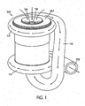
- Figure 1 is a perspective view of a double-ended blower according to a first embodiment of the present invention
- Figure 2 is a partially sectional perspective view of the double-ended blower of Figure 1 ;
- Figure 3 is a perspective view of a double-ended blower according to a second embodiment of the present invention.
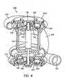
- Figure 4 is a sectional perspective view of the double-ended blower of Figure 3 ;
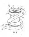
- Figure 5 is a rear perspective view of the double-ended blower of Figure 3 , illustrating the flow therethrough;
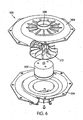
- Figure 6 is a perspective view of an in-plane transitional scroll volute suitable for use in blowers according to the present invention.
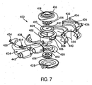
- Figure 7 is an exploded perspective view of a double-ended blower according to another embodiment of the present invention.
- Figure 8 is an assembled perspective view of the double-ended blower of Figure 7 from one side;
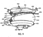
- Figure 9 is an assembled perspective view of the double-ended blower of Figure 7 from another side.
- FIG. 1 is a perspective view of a double-ended blower 100 according to a first embodiment of the present invention.
- Blower 100 has a generally cylindrical shape with impeller housings, or volutes 112, 113, disposed at each end.
- blower 100 accommodates two impellers 114, 115, which are best seen in the cut-away perspective view of Figure 2 .
- the airpath 116 of blower 100 is comprised of piping that extends from the first volute 112 to the second volute 113, the terminal ends of the airpath 116 being contoured around, and gradually fusing with, the body of blower 100 proximate to the volutes 112, 113 to form a single, integral structure.
- the airpath 116 may be comprised of rigid piping that is integrally molded with the other components of the blower 100, or it may be comprised of flexible piping (e.g., metallic or plastic flexible piping).
- Blower 100 has a single air intake 118 positioned such that air, or another suitable gas, flows directly into the first volute 112 and can be drawn in by the turning impeller 114 inside the first volute 112. Once drawn into the air intake 118, the air is circulated and pressurized by the motion of the impeller 114 before gradually exiting the volute 112 and entering the airpath 116. Once in the airpath 116, the air travels to the second volute 113, where it is further circulated and pressurized by the impeller 115 of the second volute 113 before exiting the blower 100 through the outflow conduit 120.
- the path of the air in blower 100 is indicated by the arrows in Figure 1 . As shown, in blower 100, air from the first volute 112 travels along a relatively straight section of the airpath 116 and enters the second volute 113 through an intake cavity just above the second volute 113 (not shown in Figure 1 ).
- Blower 100 could have two air intakes 118, one for each volute 112, 113, if the impellers 114, 115 are designed to work in parallel, rather than in series. This type of parallel impeller arrangement may be beneficial if installed in a low-pressure CPAP device requiring high flow rates. However, other means for generating high flow rates in a low-pressure CPAP device are known in the art.
- the design of the airpath 116 can effect the overall performance of the blower 100.
- several design considerations influence the design of an airpath for use in blowers according to the present invention.
- airpaths to be used in blowers according to the present invention are most advantageously configured to provide low flow resistance, because low flow resistance in the airpath minimizes the pressure drop between the two volutes 112, 113 in the blower.
- airpath are best configured such that the air entering the second volute 113 enters from a direction for which the blades of the impeller 115 were designed. (As will be described in more detail below, the two impellers of a blower according to the present invention may be designed to spin in the same or different directions.)
- airpaths for blowers according to the present invention are most advantageously of a compact design.
- the airpath 116 of the embodiment depicted in Figure 1 has a long, relatively straight section because the relatively straight section is one of the shortest possible paths between the two volutes 112, 113. Those skilled in the art will realize that the airpath 116 need not be straight at all.
- Blowers according to the invention may be designed manually, using prototypes and experimental measurements of air flows and pressures in those prototypes to optimize the design of the airpath 116 and other components. Alternatively, they may be designed, either as a whole or in part, by using computational fluid dynamics computer simulation programs.
- a variety of computational fluid dynamics programs are known in the art.
- Computational fluid dynamics programs particularly suited for the design of blowers according to the invention include FLOWORKS (NIKA GmbH, Sottrum, Germany), ANSYS/FLOTRAN (Ansys, Inc., Canonsburg, Pennsylvania, USA), and CFX (AEA Technology Engineering Software, Inc., El Dorado Hills, California, USA).
- Such simulation programs give the user the ability to see the effects of airpath design changes on a simulated gas flow.
- each volute is designed to retain the gas around the impeller for a short period of time, and to permit a gradual exit of gas into the airpath.
- the exact configuration of the airpath may depend on many factors, including the configuration of the volutes and the "handedness," or direction of airflow, around each impeller.
- the design of the volutes is an art unto itself, as improperly designed volutes may cause a noise, or may interfere with the generation of the desired pressure and flow characteristics.
- the computational fluid dynamics computer programs described above may also be useful in designing the volutes, although the number of variables involved in volute design usually precludes the volute from being entirely computer-designed.
- volutes 112, 113 may provide too abrupt of a transition into the airpath 116.
- An abrupt transition between the volute 112, 113 and the airpath 116 usually leaves a forked path or "lip" around the opening.
- a noise called “blade passing frequency” is created.
- Double-ended blowers according to the present invention are particularly suited for use with volutes that are constructed to reduce the occurrence of "blade passing frequency” and other noise.
- FIG. 6 is a perspective view of an in-plane transitional scroll volute 300 suitable for use in a blower according to the present invention. Additionally, the volute 300 may be employed in any conventional blower apparatus. In the view of Figure 6 , the volute 300 is provided with its own motor 302, although it may be adapted for use in a double-ended blower having a single motor driving the impellers in two volutes. As shown, the volute 300 is comprised of two halves 304, 306, the two halves defining upper and lower portions of the volute 300, respectively. The air intake of the volute 308 is located at the center of the top half 304. The two halves 304, 306 define a path which slowly "peels" away from the air rotating with the impeller.
- volute 300 depicted in Figure 6 is particularly suitable for relatively short, wide motors.
- volute any common type of volute may be used, depending on the dimensions of the motor installed in the blower.
- One important design consideration for a double-ended blower according to the present invention is the "handedness," or direction of airflow, around each impeller.
- This "handedness" may be determined by the direction in which the impeller spins, or it may be determined by the orientation and configuration of the individual blades or vanes of the impeller. For example, one impeller may be spun or the blades oriented to drive the air in a clockwise direction, and the other impeller may be spun or the blades oriented to drive the air in a counterclockwise direction, resulting in a "opposing-handed” double-ended blower. Alternatively, both impellers could be driven in the same direction, resulting in a "same-handed" double-ended blower.
- Blower 100 of Figure 1 is an example of an "opposite-handed" type of double-ended blower.
- a "same-handed" blower is advantageous because the two impellers can be identical, reducing the part count and cost of the blower. However, it should be noted that a designer may choose to design a "same-handed" blower in which the two impellers are each designed and optimized for the air flow in their respective volutes.
- An "opposing-handed" blower permits the designer to reduce the length of the shaft on which the impellers are mounted. This may increase the stability of the shaft itself, because it reduces the problems associated with having an imbalance on a long, cantilevered shaft rotating at high speed.
- FIG 3 illustrates a "same-handed" blower 200 according to the present invention.
- Blower 200 also has two volutes 212, 213, an airpath 216, an air intake 218 and an air outlet 220.
- the airpath 216 has the shape of a spiral. That is, airpath 216 transitions away from the first volute 212 and then slopes downward as it follows the circumference of the blower 200, before bending and gradually fusing with an intake cavity located between the motor 150 and the arcuate flange 160, which acts as an air intake in blower 200.
- the airflow through the blower 200 is illustrated by the arrows in the perspective view of Figure 5 .
- blower 200 The internal configuration of blower 200 is shown in the partially sectional perspective view of Figure 4 .
- the internal arrangements of blowers 100 and 200 are substantially similar, and will be described below with respect to components of both blowers, where applicable.
- an electric motor 150 is installed in the center of the blowers 200.
- brackets and mountings may be used to support the motor and to secure it to the interior of the blower 200, although for simplicity, these are not shown in Figure 4 .
- the motor 150 drives a single shaft 152.
- the shaft 152 traverses substantially the entire length of the blower 100, 200 along its center, and is secured to an impeller 114, 115, 214 at each end.
- the shaft may be round, square, keyed, or otherwise shaped to transmit power to the two impellers 114, 115, 214.
- the connection between the impellers 114, 115, 214 and the shaft 152 may be created by an interference fit between the two parts, a weld, an adhesive, or fasteners, such as set screws.
- connection between the shaft 152 and the impellers 114, 115, 214 is by means of a vertically oriented (i.e., oriented along the axis of the shaft 152) annular flange 154 formed in the center of the impellers 114, 115, 214.
- a vertically oriented i.e., oriented along the axis of the shaft 152
- annular flange 154 formed in the center of the impellers 114, 115, 214.
- the connection between the impellers 114, 115, 214 and the shaft is shown as an interference fit.
- the impeller 114, 115, 214 is substantially annular in shape.
- the center section 156 of the impeller 114, 115, 214 is a thin plate which extends radially outward from the shaft 152 to the blades 158, and is upswept, gradually curving downward as it extends outward from the shaft 152 towards the blades 158.
- the actual diameter of each impeller 114, 115, 214 may be smaller than that of a conventional blower with a single impeller. Fast pressure rise time in a blower requires a low rotational inertia, which varies as the diameter to the fourth power.
- impeller 114 and 214 of blowers 100 and 200 are smaller in diameter, they have less rotational inertia, and thus, are able to provide a faster pressure rise time.
- other design parameters of the impellers 114, 214 may be modified to achieve a lower rotational inertia.
- Other techniques to reduce rotational inertia include "scalloping" the shrouds to produce a "starfish-shaped" impeller, using an internal rotor motor, and using materials, such as liquid crystal polymer, that can be molded into thinner wall sections, so that impeller blades can be hollowed out and strengthened by ribs.
- the top of the first volute 212 is open, forming the air intake 118.
- the top surface 121 of the blower 100 curves arcuately inward, forming a lip 122 over the top of the impeller 214.
- the upswept shape of the impeller center section 156 and the lip 122 of the top surface 121 confine the incoming air to the blower volume inside the first volute 212 and help to prevent air leakage during operation.
- An arcuate flange 160 similar to the arcuate top surface 121 extends from the lower interior surface of the blower 200, forming the top of the second volute 213.
- a contoured bottom plate 162, 262 forms the bottom of the second volute 113, 213 of each blower 100, 200.
- the bottom plate 162 of blower 100 has a hole in its center, allowing the airpath 116 to enter, while the bottom plate 262 of blower 200 has no such hole.
- the arcuate flange 160 acts as the air intake for the second volute 213 of blower 200.
- stator vanes and additional flow shaping components may be added to the cavity between the motor 150 and the arcuate flange 160 to assist in distributing the incoming air so that it enters the second volute 213 from all sides, rather than preferentially from one side.
- blowers according to the present invention may have many intricate and contoured surfaces. Such contours are used, as in the case of the arcuate top surface 121 and arcuate flange 160, to direct gas flow and prevent gas leakage.
- the no-leak requirement is particularly important when the gas flowing through the blower 100, 200 has a high concentration of oxygen gas. If high-concentration oxygen is used, gas leakage may pose a safety hazard. Also, apart from any safety considerations, leaking gas may produce unwanted noise, and may reduce blower performance.
- blowers make a production method such as investment casting particularly suitable.
- investment casting can produce a single part with many hidden and re-entrant features, whereas other methods of production may require that a design be split into many parts to achieve equivalent function.
- a large number of parts is generally undesirable - in order to minimize the potential for gas leaks, the number of parts is best kept to a minimum and the number of joints between parts is also best kept to a minimum.
- blowers There are also a number of materials considerations for blowers according to the present invention. Metals are typically used in investment casting, but some metals are particularly sensitive to oxidation, which is a concern because medical grade oxygen gas may be used in blowers according to the present invention.
- One particularly suitable material for the blowers 100, 200 is aluminum. Whereas steel may rust on exposure to high concentrations of oxygen, aluminum oxidizes quickly, the oxide forming an impervious seal over the metal. Whichever metal or other material is used, it is also important that the material has a high thermal conductivity and is able to draw heat away from the airpath, to prevent any heat-related ignition of oxygen.
- damping materials may be installed in an aluminum blower to reduce the intensity of the vibration of the aluminum components.
- blowers 100 and 200 the electric motor 150 is driven at variable speeds to achieve the desired IPAP and EPAP pressures.
- the double-ended (i.e., two-stage) design of the blowers means that the range of motor speeds traversed to achieve the two pressures is reduced.
- the narrower range of motor speeds results in a faster pressure response time than that provided by a single-stage blower having similar motor power and drive characteristics.
- the narrower variation in speed applies less stress to the rotating system components, resulting in increased reliability with less acoustic noise.
- blowers 100 and 200 The performance of blowers 100 and 200 is approximately equal to the combined performance of the two impeller/volute combinations, minus the pressure/flow curve of the airpath 116, 216 between the two volutes 112, 113, 212, 213.
- the actual performance of the blowers 100, 200 will depend upon the instantaneous flow rate of the particular blower 100, 200, as well as a number of factors. At higher flow rates, the pressure drop in the airpath 116, 216 is generally more significant.
- Double-ended blowers according to the present invention may be placed in a CPAP apparatus in the same manner as a conventional blower.
- the blower is typically mounted on springs, or another shock-absorbing structure, to reduce vibrations.
- FIG. 7 an exploded perspective view of a double-ended blower 400 according to the present invention.
- the motor and stator blade portion 402 located in the center of the exploded view, is investment cast from aluminum in this embodiment, although other manufacturing methods are possible and will be described below.
- the aluminum as a good conductor of heat, facilitates the dissipation of heat generated by the accelerating and decelerating motor.
- Each end of the shaft 404 is shown in Figure 7 , but the motor windings, bearing and cover are not shown.
- the motor power cord 406 protrudes from the motor and stator blade portion 402 and exits the blower 400 through a sealed orifice 450.
- the motor and stator blade portion 402 includes, at its top, a bottom portion of the upper volute 408.
- the motor and stator blade portion 402 may be made separately from the bottom portion of the upper volute 408. If the two components are made separately, investment casting would not be required.
- the motor body may be die cast, while the bottom portion of the upper volute 408 may be injection molded.
- a circular plate 410 Secured to the motor and stator blade portion 402 by bolts or other fasteners is a circular plate 410, in which a hole 412 is provided for the passage of the shaft 404.
- An impeller 414 rests atop the circular plate. The impeller 414 is scalloped along its circumference to reduce its rotational inertia, giving it a "starfish" look.
- An upper endcap 416 is secured above the impeller 414, and provides the top portion of the upper volute.
- the upper and lower volutes in this embodiment are versions of the in-plane transitional scroll volute 300 illustrated in Figure 6 .
- An aperture 418 in the center of the upper endcap 416 serves as the air intake of the blower 400.
- a contoured plate 420 forms the top portion of the lower volute.
- the top of the contoured plate 420 is raised and curves arcuately downward toward a hole 422.
- the contoured plate 420 helps to shape the airflow and to ensure that it enters the impeller cavity from all sides, rather than preferentially from a single direction.
- Beneath the contoured plate 420 a lower impeller 414 rotates proximate to a lower endcap 428.
- the two endcaps, 416, 428 may be die cast (e.g., from aluminum or magnesium alloy) or they may be injection molded from an appropriate metal.
- the airpath 454 between the upper and lower volutes is an integral part of the left 424 and right 426 side casings, onto which the other components are secured.
- the left side casing 424 also provides the air outlet 442 for the blower 400.
- the left 424 and right 426 side casings are secured together with bolts or other removable fasteners.
- On the top surface of the side casings 424, 426 are square flanges 430, 432 having protrusions 434, 436 that allow the blower 400 to be mounted on springs inside a CPAP apparatus.
- the protrusions 434, 436 are shown as having different sizes and shapes, however, in Figures 8 and 9 , the protrusions 434 are shown as having the same shape. It will be realized that the protrusions 434, 436 may take either of the depicted shapes, or any other shape, depending on the properties and arrangement of the springs onto which the blower 400 is mounted.
- the double-ended blower 400 also includes two damping sleeves 438, 440.
- the damping sleeves 438, 440 are rubber or foam rubber components that are injection molded to match the internal contours of the left 424 and right 426 side casings, respectively.
- the damping sleeves 438, 440 are 40 Shore A hardness polyurethane formed from a rapid prototype silicone mold.
- the damping sleeves 438, 440 could be silicone, or another elastomer that is stable at the high temperatures generated by the motor.
- the damping sleeves 438, 440 serve three major purposes in blower 400: they form the actual airpath 454, they provide a seal between the other components, and they dampen the vibrations of the other parts.
- the rubber or foam rubber material of the damping sleeves 438, 440 is particularly suitable for the airpath 454, as it allows for re-entrant molds (i.e., undercuts).
- the damping properties of the damping sleeves 438, 440 reduce the "ringing" of the aluminum components that would otherwise be experienced.
- Figure 8 is an assembled perspective view of blower 400 from one side.
- the assembled air outlet 442 is shown in Figure 8 , as is the seam 444 between the left 424 and right 426 side casings.
- flanges 446, 448 protrude laterally from the edge of each side casing 424, 426 and abut to form the seam 444.
- the two side casings 424, 426 are secured together by bolts 452 that pass through the flange 446 provided in the right side casing 426 and into threaded holes provided in the flange 448 of the left side casing 424.
- Blower 400 has several advantages. First, investment casting is not required to produce blower 400, which reduces the cost of the blower. Additionally, because the components of blower 400 have fewer hidden and intricate parts, the castings can be inspected and cleaned easily. Finally, blower 400 is easier to assemble than the other embodiments because the components are clamped together using the two side casings 424, 426, which can be done with simple fasteners.
Claims (14)
- Kontinuierliche positive Atemwegdruck-/nichtinvasive positive Druckbeatmungs- (CPAP/NIPPV-) Vorrichtung (100, 200, 400) zur Behandlung eines Patienten mit einer Schlafstörung, wobei die Vorrichtung (100, 200, 400) aufweist:ein Gehäuse;einen Gasströmungsweg (116, 216, 454) zwischen einem Gaseinlass (118, 418) und einem Gasauslass (120, 442); einen Motor (150); undeine Laufradanordnung, wobei die Laufradanordnung aufweist: eine Welle (152, 404) in Kommunikation mit dem Motor (150) zur Drehbewegung um eine erste Achse sowie ein erstes und ein zweites Laufrad (114, 115, 214, 414), die gesichert mit der Welle (152, 404) gekoppelt sind,wobei das erste und zweite Laufrad (114, 115, 214, 414) in Fluidkommunikation miteinander durch den Gasströmungsweg (116, 216, 454) so platziert sind, dass beide Laufräder (114, 115, 214, 414) zwischen dem Gaseinlass (118, 418) und dem Gasauslass (120, 442) angeordnet sind, um zusammenwirkend Gas unter Druck zu setzen, das vom Gaseinlass (118, 418) zum Gasauslass (120, 442) strömt,
dadurch gekennzeichnet, dassdas Gehäuse eine erste und eine zweite Spirale (112, 113, 212, 213, 408) aufweist, wobei die erste Spirale (112, 212, 408) die Gasströmung um das erste Laufrad (114, 214, 414) enthält und die zweite Spirale (113, 213) Gasströmung um das zweite Laufrad (115, 214, 414) enthält. - CPAP/NIPPV-Vorrichtung nach Anspruch 1, wobei die Laufräder (114, 115, 214, 414) zwischen dem Gaseinlass (118, 418) und Gasauslass (120, 442) in Reihe angeordnet sind.
- CPAP/NIPPV-Vorrichtung nach Anspruch 1 oder 2, wobei das Gehäuse aus Aluminium hergestellt ist.
- CPAP/NIPPV-Vorrichtung nach einem der Ansprüche 1 bis 3, wobei der Gaseinlass (118, 418) in der ersten Spirale (112, 212, 408) liegt und der Gasauslass (120, 442) in der zweiten Spirale (113, 213) liegt.
- CPAP/NIPPV-Vorrichtung nach einem der Ansprüche 1 bis 4, wobei die Laufräder (114, 115, 214, 414) entlang der ersten Achse senkrecht voneinander beabstandet sind, wobei die Laufräder (114, 115, 214, 414) jeweils an entgegengesetzten Enden des Motors (150) angeordnet sind.
- CPAP/NIPPV-Vorrichtung nach einem der Ansprüche 1 bis 5, ferner mit einer Hülse, die um das erste und zweite Laufrad (114, 115, 214, 414) angeordnet ist und einen Abschnitt des Gaswegs (116, 216, 454) definiert, der sich vom ersten Laufrad (114, 214, 414) zum zweiten Laufrad (115, 214, 414) erstreckt.
- CPAP/NIPPV-Vorrichtung nach Anspruch 6, wobei eine Innenfläche der Hülse benachbart zu einem Motorständer des Motors (150) gebildet ist, um den Luftweg zwischen dem Motorständer und der Innenfläche festzulegen.
- CPAP/NIPPV-Vorrichtung nach Anspruch 6 oder 7, wobei das Gehäuse an der Hülse vorgesehen ist und sie umgibt.
- CPAP/NIPPV-Vorrichtung nach Anspruch 8, wobei die Hülse und/oder das Gehäuse eine erste und eine zweite Hälfte aufweisen.
- CPAP/NIPPV-Vorrichtung nach einem der Ansprüche 6 bis 9, wobei die Hülse aus Silikon oder einem anderen Elastomer, Gummi, Schaumgummi oder Polyurethan hergestellt ist.
- CPAP/NIPPV-Vorrichtung nach einem der Ansprüche 1 bis 10, ferner mit einer Endkappe benachbart zum ersten Laufrad (114, 214, 414), wobei die Endkappe einen Einlass für das erste Laufrad (114, 214, 414) in Form einer mittleren Einlassöffnung aufweist.
- CPAP/NIPPV-Vorrichtung nach Anspruch 11, wobei die Endkappe und ein Abschnitt eines Motorständers des Motors (150) die erste Spirale (112, 212, 408) für das erste Laufrad (114, 214, 414) definieren.
- CPAP/NIPPV-Vorrichtung nach einem der Ansprüche 1 bis 12, wobei die CPAP/NIPPV-Vorrichtung (100, 200, 400) so voreingestellt ist, dass sie inspiratorischen positiven Atemwegdruck (IPAP) während der Inspirationsphase des Atemzyklus des Patienten abgibt und exspiratorischen positiven Atemwegdruck (EPAP) während der Exspiration des Atemzyklus des Patienten abgibt, wobei der IPAP größer als der EPAP ist.
- CPAP/NIPPV-Vorrichtung nach einem der Ansprüche 1 bis 13, wobei das Gebläse (100, 200, 400) so konfiguriert ist, dass es Drücke im Bereich von etwa 4 cm H2O bis 28 cm H2O bei Strömungsgeschwindigkeiten bis etwa 180 l/min gemessen an der Patientenschnittstelle erzeugt.
Applications Claiming Priority (4)
| Application Number | Priority Date | Filing Date | Title |
|---|---|---|---|
| US33716901P | 2001-12-10 | 2001-12-10 | |
| EP05028723A EP1643131B1 (de) | 2001-12-10 | 2002-12-10 | Zweiseitiges Gebläse und Spiralgehäuse dazu |
| EP08157382A EP1985861B1 (de) | 2001-12-10 | 2002-12-10 | Gebläsevorrichtung der CPAP/NIPPV-Art |
| EP02445171A EP1318307B1 (de) | 2001-12-10 | 2002-12-10 | Zweiseitiges Gebläse und Spiralgehäuse dazu |
Related Parent Applications (3)
| Application Number | Title | Priority Date | Filing Date |
|---|---|---|---|
| EP02445171.8 Division | 2002-12-10 | ||
| EP05028723.4 Division | 2005-12-30 | ||
| EP08157382.6 Division | 2008-06-02 |
Publications (2)
| Publication Number | Publication Date |
|---|---|
| EP2287471A1 EP2287471A1 (de) | 2011-02-23 |
| EP2287471B1 true EP2287471B1 (de) | 2012-06-27 |
Family
ID=23319402
Family Applications (4)
| Application Number | Title | Priority Date | Filing Date |
|---|---|---|---|
| EP02445171A Expired - Lifetime EP1318307B1 (de) | 2001-12-10 | 2002-12-10 | Zweiseitiges Gebläse und Spiralgehäuse dazu |
| EP10182132A Expired - Lifetime EP2287471B1 (de) | 2001-12-10 | 2002-12-10 | Gebläsevorrichtung der CPAP/NIPPV-Art |
| EP08157382A Expired - Lifetime EP1985861B1 (de) | 2001-12-10 | 2002-12-10 | Gebläsevorrichtung der CPAP/NIPPV-Art |
| EP05028723A Expired - Lifetime EP1643131B1 (de) | 2001-12-10 | 2002-12-10 | Zweiseitiges Gebläse und Spiralgehäuse dazu |
Family Applications Before (1)
| Application Number | Title | Priority Date | Filing Date |
|---|---|---|---|
| EP02445171A Expired - Lifetime EP1318307B1 (de) | 2001-12-10 | 2002-12-10 | Zweiseitiges Gebläse und Spiralgehäuse dazu |
Family Applications After (2)
| Application Number | Title | Priority Date | Filing Date |
|---|---|---|---|
| EP08157382A Expired - Lifetime EP1985861B1 (de) | 2001-12-10 | 2002-12-10 | Gebläsevorrichtung der CPAP/NIPPV-Art |
| EP05028723A Expired - Lifetime EP1643131B1 (de) | 2001-12-10 | 2002-12-10 | Zweiseitiges Gebläse und Spiralgehäuse dazu |
Country Status (6)
| Country | Link |
|---|---|
| EP (4) | EP1318307B1 (de) |
| JP (3) | JP4497809B2 (de) |
| CN (2) | CN100457214C (de) |
| AT (3) | ATE318375T1 (de) |
| AU (3) | AU2002315917B2 (de) |
| DE (3) | DE60227013D1 (de) |
Cited By (9)
| Publication number | Priority date | Publication date | Assignee | Title |
|---|---|---|---|---|
| USD741474S1 (en) | 2013-08-22 | 2015-10-20 | Fresca Medical, Inc. | Sleep apnea device accessory |
| USD742501S1 (en) | 2013-07-18 | 2015-11-03 | Fresca Medical, Inc. | Sleep apnea device |
| USD742502S1 (en) | 2013-07-18 | 2015-11-03 | Fresca Medical, Inc. | Sleep apnea device |
| USD743021S1 (en) | 2013-07-18 | 2015-11-10 | Fresca Medical, Inc. | Sleep apnea device |
| USD745139S1 (en) | 2013-08-16 | 2015-12-08 | Fresca Medical, Inc. | Sleep apnea device |
| USD749205S1 (en) | 2013-03-08 | 2016-02-09 | Fresca Medical, Inc. | Sleep apnea device |
| US9333318B2 (en) | 2012-04-13 | 2016-05-10 | Fresca Medical, Inc. | Sleep apnea device |
| USD759230S1 (en) | 2014-05-30 | 2016-06-14 | Fresca Medical, Inc. | Airflow generator for a sleep apnea system |
| US9492086B2 (en) | 2012-03-21 | 2016-11-15 | Fresca Medical, Inc. | Apparatus, systems, and methods for treating obstructive sleep apnea |
Families Citing this family (46)
| Publication number | Priority date | Publication date | Assignee | Title |
|---|---|---|---|---|
| ATE342084T1 (de) | 1999-08-05 | 2006-11-15 | Map Medizin Technologie Gmbh | Vorrichtung zur zufuhr eines atemgases und befeuchtungsvorrichtung |
| WO2002066106A1 (en) | 2001-02-16 | 2002-08-29 | Resmed Limited | Humidifier with structure to prevent backflow of liquid through the humidifier inlet |
| US8517012B2 (en) | 2001-12-10 | 2013-08-27 | Resmed Limited | Multiple stage blowers and volutes therefor |
| JP4497809B2 (ja) * | 2001-12-10 | 2010-07-07 | レスメド・リミテッド | 送風機 |
| US6910483B2 (en) | 2001-12-10 | 2005-06-28 | Resmed Limited | Double-ended blower and volutes therefor |
| JP2006527324A (ja) * | 2003-06-10 | 2006-11-30 | レスメド リミテッド | 多段送風機及びそのためのエンクロージャ |
| AU2013201490B2 (en) * | 2003-06-20 | 2014-09-25 | ResMed Pty Ltd | Breathable Gas Apparatus with Humidifier |
| AU2003903139A0 (en) | 2003-06-20 | 2003-07-03 | Resmed Limited | Breathable gas apparatus with humidifier |
| CN104353165B (zh) | 2003-06-20 | 2017-08-22 | 瑞思迈有限公司 | 带有加湿器的可吸入气体设备 |
| US7913692B2 (en) | 2003-09-25 | 2011-03-29 | Resmed Limited | CPAP mask and system |
| US7014418B1 (en) * | 2004-12-03 | 2006-03-21 | Honeywell International, Inc. | Multi-stage compressor and housing therefor |
| AU2006308435B2 (en) | 2005-10-28 | 2013-02-14 | Resmed Motor Technologies Inc. | Single or multiple stage blower and nested volute(s) and/or impeller(s) therefor |
| US20070231164A1 (en) * | 2005-12-14 | 2007-10-04 | Eybergen William N | Fuel cell compressor system |
| DE102005060329A1 (de) * | 2005-12-16 | 2007-06-21 | Dietz-Motoren Gmbh & Co. Kg | Hochdruckventilator |
| JP4804186B2 (ja) * | 2006-03-28 | 2011-11-02 | キヤノン株式会社 | シート給送装置及び画像形成装置 |
| NZ589602A (en) | 2006-05-24 | 2012-02-24 | Resmed Motor Technologies Inc | Low noise blower for CPAP devices with a shield to isolate the stator vane from the impeller pressure pulse |
| EP2063945B1 (de) | 2006-09-07 | 2019-07-03 | ResMed Ltd. | Maske und flussgeneratorsystem |
| EP3871721A1 (de) | 2006-10-24 | 2021-09-01 | ResMed Motor Technologies Inc | Bürstenloser gleichstrommotor mit lagern |
| US8365726B2 (en) | 2007-06-07 | 2013-02-05 | Resmed Limited | Tub for humidifier |
| EP2085106B1 (de) | 2008-01-31 | 2017-07-19 | ResMed Limited | Beatmungsgerät |
| JP5109695B2 (ja) | 2008-02-06 | 2012-12-26 | 株式会社Ihi | ターボ圧縮機及び冷凍機 |
| NZ742900A (en) | 2008-06-05 | 2020-02-28 | ResMed Pty Ltd | Treatment of respiratory conditions by automatic control of flow and/or temperature and/or humidity independently to nares via separate flow paths |
| US20100059055A1 (en) * | 2008-09-05 | 2010-03-11 | Brungart Timothy A | Gas delivery system including a flow generator having an isolated blower assembly for noise reduction |
| US10238822B2 (en) | 2009-05-29 | 2019-03-26 | Resmed Limited | PAP system |
| US8931481B2 (en) | 2009-06-04 | 2015-01-13 | Redmed Limited | Flow generator chassis assembly with suspension seal |
| CN115177828A (zh) | 2009-08-28 | 2022-10-14 | 瑞思迈私人有限公司 | Pap系统 |
| EP2317150B1 (de) | 2009-10-29 | 2019-12-18 | ResMed Pty Ltd | Patientenbeatmungsvorrichtung und Komponenten davon |
| EP4039301A1 (de) | 2009-11-19 | 2022-08-10 | ResMed Motor Technologies Inc. | Gebläse |
| JP5747632B2 (ja) * | 2011-04-26 | 2015-07-15 | 日本電産株式会社 | 遠心ファン |
| US9017893B2 (en) | 2011-06-24 | 2015-04-28 | Watt Fuel Cell Corp. | Fuel cell system with centrifugal blower system for providing a flow of gaseous medium thereto |
| US10085674B2 (en) | 2011-09-22 | 2018-10-02 | Koninklijke Philips N.V. | Method and apparatus for monitoring and controlling a pressure support device |
| US9669172B2 (en) * | 2012-07-05 | 2017-06-06 | Resmed Limited | Discreet respiratory therapy system |
| JP5211302B1 (ja) | 2012-09-03 | 2013-06-12 | 株式会社メトラン | 送風機 |
| CN102937101B (zh) * | 2012-11-21 | 2015-05-06 | 王卫 | 一种自增压低压大流量气泵 |
| JP5358773B1 (ja) | 2013-02-21 | 2013-12-04 | 株式会社メトラン | 呼吸補助装置 |
| KR20180021259A (ko) | 2013-07-05 | 2018-02-28 | 가부시키가이샤 아이에이치아이 | 터보 압축기의 유량 계측 장치 및 터보 압축기 |
| EP3112686A4 (de) | 2014-02-25 | 2017-01-04 | Mitsubishi Heavy Industries, Ltd. | Elektrischer mehrstufiger radialverdichter und aufladesystem einer brennkraftmaschine |
| JP2018087494A (ja) * | 2015-03-30 | 2018-06-07 | 株式会社デンソー | 送風装置 |
| JP2018087495A (ja) * | 2015-03-30 | 2018-06-07 | 株式会社デンソー | 送風装置 |
| JP6940414B2 (ja) * | 2015-04-20 | 2021-09-29 | レスメッド センサー テクノロジーズ リミテッド | 特性信号から人間の検出及び識別 |
| JP6346914B2 (ja) * | 2016-05-13 | 2018-06-20 | アトムメディカル株式会社 | 呼吸用気体の供給装置 |
| JP6744798B2 (ja) * | 2016-10-18 | 2020-08-19 | 貞義 竹綱 | 耐熱電動送風機 |
| USD899598S1 (en) | 2018-09-04 | 2020-10-20 | 3B Medical, Inc. | CPAP device |
| CN112682339B (zh) * | 2021-03-15 | 2021-07-09 | 亿昇(天津)科技有限公司 | 一种双吸式真空泵系统 |
| CN113757145A (zh) * | 2021-09-14 | 2021-12-07 | 杭州贝丰科技有限公司 | 风机 |
| CN114165465B (zh) * | 2021-12-20 | 2022-10-18 | 东北大学 | 一种具有双出口可调节结构蜗壳的离心式风机 |
Family Cites Families (18)
| Publication number | Priority date | Publication date | Assignee | Title |
|---|---|---|---|---|
| DE275612C (de) * | ||||
| FR2408739A1 (fr) * | 1977-11-10 | 1979-06-08 | Materiel Telephonique | Dispositif de pompage monobloc a fonctionnement ambivalent |
| FR2528127A1 (fr) * | 1982-06-04 | 1983-12-09 | Creusot Loire | Moto-compresseur centrifuge electrique integre a grande vitesse |
| DE3729486C1 (de) * | 1987-09-03 | 1988-12-15 | Gutehoffnungshuette Man | Kompressoreinheit |
| JPH04159500A (ja) * | 1990-10-22 | 1992-06-02 | Hitachi Ltd | 遠心送風機 |
| JPH0589887U (ja) * | 1992-05-08 | 1993-12-07 | 日本聖器株式会社 | 圧縮袋用専用ポンプ |
| JPH07259798A (ja) * | 1994-03-23 | 1995-10-09 | Aisin Seiki Co Ltd | 遠心送風機 |
| US5888053A (en) * | 1995-02-10 | 1999-03-30 | Ebara Corporation | Pump having first and second outer casing members |
| FI101564B (fi) * | 1997-01-17 | 1998-07-15 | Flaekt Woods Ab | Korkeapainepuhallin |
| CA2303970C (en) * | 1997-09-19 | 2009-09-08 | Respironics, Inc. | Medical ventilator |
| AUPP015097A0 (en) * | 1997-11-03 | 1997-11-27 | Resmed Limited | A mounting body |
| JP3910703B2 (ja) * | 1997-11-14 | 2007-04-25 | 株式会社共立 | 携帯型送風作業機 |
| WO1999064747A1 (en) * | 1998-06-11 | 1999-12-16 | Resmed Limited | A housing for a centrifugal impeller |
| DE19901780C1 (de) * | 1999-01-18 | 2000-05-25 | Map Gmbh | Gebläseeinrichtung |
| JP3475174B2 (ja) * | 2000-02-10 | 2003-12-08 | 東芝テック株式会社 | 電動ポンプ |
| US6553763B1 (en) * | 2001-08-30 | 2003-04-29 | Caterpillar Inc | Turbocharger including a disk to reduce scalloping inefficiencies |
| JP2005508482A (ja) * | 2001-11-08 | 2005-03-31 | ボーグワーナー・インコーポレーテッド | 2段電動コンプレッサ |
| JP4497809B2 (ja) * | 2001-12-10 | 2010-07-07 | レスメド・リミテッド | 送風機 |
-
2002
- 2002-12-10 JP JP2002358775A patent/JP4497809B2/ja not_active Expired - Lifetime
- 2002-12-10 EP EP02445171A patent/EP1318307B1/de not_active Expired - Lifetime
- 2002-12-10 EP EP10182132A patent/EP2287471B1/de not_active Expired - Lifetime
- 2002-12-10 AT AT02445171T patent/ATE318375T1/de not_active IP Right Cessation
- 2002-12-10 AU AU2002315917A patent/AU2002315917B2/en not_active Ceased
- 2002-12-10 AT AT08157382T patent/ATE497584T1/de not_active IP Right Cessation
- 2002-12-10 CN CNB021542899A patent/CN100457214C/zh not_active Expired - Fee Related
- 2002-12-10 EP EP08157382A patent/EP1985861B1/de not_active Expired - Lifetime
- 2002-12-10 CN CN200910001413.0A patent/CN101450237B/zh not_active Expired - Fee Related
- 2002-12-10 DE DE60227013T patent/DE60227013D1/de not_active Expired - Lifetime
- 2002-12-10 DE DE60209328T patent/DE60209328T2/de not_active Expired - Lifetime
- 2002-12-10 DE DE60239114T patent/DE60239114D1/de not_active Expired - Lifetime
- 2002-12-10 AT AT05028723T patent/ATE397727T1/de not_active IP Right Cessation
- 2002-12-10 EP EP05028723A patent/EP1643131B1/de not_active Expired - Lifetime
-
2008
- 2008-04-30 AU AU2008201916A patent/AU2008201916B2/en not_active Ceased
- 2008-09-30 JP JP2008253988A patent/JP4995797B2/ja not_active Expired - Lifetime
-
2010
- 2010-12-07 AU AU2010249207A patent/AU2010249207B2/en not_active Ceased
-
2011
- 2011-10-13 JP JP2011226073A patent/JP5350453B2/ja not_active Expired - Fee Related
Cited By (9)
| Publication number | Priority date | Publication date | Assignee | Title |
|---|---|---|---|---|
| US9492086B2 (en) | 2012-03-21 | 2016-11-15 | Fresca Medical, Inc. | Apparatus, systems, and methods for treating obstructive sleep apnea |
| US9333318B2 (en) | 2012-04-13 | 2016-05-10 | Fresca Medical, Inc. | Sleep apnea device |
| USD749205S1 (en) | 2013-03-08 | 2016-02-09 | Fresca Medical, Inc. | Sleep apnea device |
| USD742501S1 (en) | 2013-07-18 | 2015-11-03 | Fresca Medical, Inc. | Sleep apnea device |
| USD742502S1 (en) | 2013-07-18 | 2015-11-03 | Fresca Medical, Inc. | Sleep apnea device |
| USD743021S1 (en) | 2013-07-18 | 2015-11-10 | Fresca Medical, Inc. | Sleep apnea device |
| USD745139S1 (en) | 2013-08-16 | 2015-12-08 | Fresca Medical, Inc. | Sleep apnea device |
| USD741474S1 (en) | 2013-08-22 | 2015-10-20 | Fresca Medical, Inc. | Sleep apnea device accessory |
| USD759230S1 (en) | 2014-05-30 | 2016-06-14 | Fresca Medical, Inc. | Airflow generator for a sleep apnea system |
Also Published As
| Publication number | Publication date |
|---|---|
| ATE497584T1 (de) | 2011-02-15 |
| ATE397727T1 (de) | 2008-06-15 |
| EP1985861A3 (de) | 2008-11-12 |
| AU2010249207A1 (en) | 2011-01-06 |
| JP2012017744A (ja) | 2012-01-26 |
| CN100457214C (zh) | 2009-02-04 |
| JP4497809B2 (ja) | 2010-07-07 |
| EP1318307A1 (de) | 2003-06-11 |
| AU2008201916A1 (en) | 2008-05-22 |
| JP4995797B2 (ja) | 2012-08-08 |
| CN101450237B (zh) | 2012-03-28 |
| EP1985861B1 (de) | 2011-02-02 |
| AU2002315917B2 (en) | 2008-05-01 |
| ATE318375T1 (de) | 2006-03-15 |
| DE60209328D1 (de) | 2006-04-27 |
| CN1432415A (zh) | 2003-07-30 |
| EP1643131A3 (de) | 2006-04-19 |
| EP1643131A9 (de) | 2006-12-13 |
| DE60239114D1 (de) | 2011-03-17 |
| JP2009041572A (ja) | 2009-02-26 |
| EP1318307B1 (de) | 2006-02-22 |
| EP1643131A2 (de) | 2006-04-05 |
| DE60227013D1 (de) | 2008-07-17 |
| DE60209328T2 (de) | 2006-10-12 |
| AU2010249207B2 (en) | 2012-08-30 |
| JP5350453B2 (ja) | 2013-11-27 |
| EP1643131B1 (de) | 2008-06-04 |
| EP2287471A1 (de) | 2011-02-23 |
| EP1985861A2 (de) | 2008-10-29 |
| JP2003214395A (ja) | 2003-07-30 |
| AU2008201916B2 (en) | 2010-09-09 |
| CN101450237A (zh) | 2009-06-10 |
| EP1643131A8 (de) | 2006-10-11 |
Similar Documents
| Publication | Publication Date | Title |
|---|---|---|
| EP2287471B1 (de) | Gebläsevorrichtung der CPAP/NIPPV-Art | |
| US6910483B2 (en) | Double-ended blower and volutes therefor | |
| US10300231B2 (en) | Multiple stage blowers and volutes therefor | |
| AU2011202113B2 (en) | Multiple Stage Blower and Enclosure Therefor |
Legal Events
| Date | Code | Title | Description |
|---|---|---|---|
| PUAI | Public reference made under article 153(3) epc to a published international application that has entered the european phase |
Free format text: ORIGINAL CODE: 0009012 |
|
| AC | Divisional application: reference to earlier application |
Ref document number: 1643131 Country of ref document: EP Kind code of ref document: P Ref document number: 1985861 Country of ref document: EP Kind code of ref document: P Ref document number: 1318307 Country of ref document: EP Kind code of ref document: P |
|
| AK | Designated contracting states |
Kind code of ref document: A1 Designated state(s): AT BE BG CH CY CZ DE DK EE ES FI FR GB GR IE IT LI LU MC NL PT SE SI SK TR |
|
| 17P | Request for examination filed |
Effective date: 20110614 |
|
| GRAP | Despatch of communication of intention to grant a patent |
Free format text: ORIGINAL CODE: EPIDOSNIGR1 |
|
| RIC1 | Information provided on ipc code assigned before grant |
Ipc: A61M 16/00 20060101ALI20111103BHEP Ipc: F04D 25/08 20060101ALI20111103BHEP Ipc: F04D 17/16 20060101ALI20111103BHEP Ipc: F04D 25/16 20060101ALI20111103BHEP Ipc: F04D 17/12 20060101AFI20111103BHEP |
|
| GRAS | Grant fee paid |
Free format text: ORIGINAL CODE: EPIDOSNIGR3 |
|
| GRAA | (expected) grant |
Free format text: ORIGINAL CODE: 0009210 |
|
| AC | Divisional application: reference to earlier application |
Ref document number: 1318307 Country of ref document: EP Kind code of ref document: P Ref document number: 1643131 Country of ref document: EP Kind code of ref document: P Ref document number: 1985861 Country of ref document: EP Kind code of ref document: P |
|
| AK | Designated contracting states |
Kind code of ref document: B1 Designated state(s): AT BE BG CH CY CZ DE DK EE ES FI FR GB GR IE IT LI LU MC NL PT SE SI SK TR |
|
| REG | Reference to a national code |
Ref country code: GB Ref legal event code: FG4D |
|
| REG | Reference to a national code |
Ref country code: CH Ref legal event code: EP |
|
| REG | Reference to a national code |
Ref country code: SE Ref legal event code: TRGR |
|
| REG | Reference to a national code |
Ref country code: AT Ref legal event code: REF Ref document number: 564399 Country of ref document: AT Kind code of ref document: T Effective date: 20120715 |
|
| REG | Reference to a national code |
Ref country code: IE Ref legal event code: FG4D |
|
| REG | Reference to a national code |
Ref country code: CH Ref legal event code: NV Representative=s name: VOSSIUS & PARTNER |
|
| REG | Reference to a national code |
Ref country code: DE Ref legal event code: R096 Ref document number: 60243250 Country of ref document: DE Effective date: 20120823 |
|
| PG25 | Lapsed in a contracting state [announced via postgrant information from national office to epo] |
Ref country code: FI Free format text: LAPSE BECAUSE OF FAILURE TO SUBMIT A TRANSLATION OF THE DESCRIPTION OR TO PAY THE FEE WITHIN THE PRESCRIBED TIME-LIMIT Effective date: 20120627 |
|
| REG | Reference to a national code |
Ref country code: NL Ref legal event code: VDEP Effective date: 20120627 |
|
| REG | Reference to a national code |
Ref country code: AT Ref legal event code: MK05 Ref document number: 564399 Country of ref document: AT Kind code of ref document: T Effective date: 20120627 |
|
| PG25 | Lapsed in a contracting state [announced via postgrant information from national office to epo] |
Ref country code: SI Free format text: LAPSE BECAUSE OF FAILURE TO SUBMIT A TRANSLATION OF THE DESCRIPTION OR TO PAY THE FEE WITHIN THE PRESCRIBED TIME-LIMIT Effective date: 20120627 Ref country code: GR Free format text: LAPSE BECAUSE OF FAILURE TO SUBMIT A TRANSLATION OF THE DESCRIPTION OR TO PAY THE FEE WITHIN THE PRESCRIBED TIME-LIMIT Effective date: 20120928 |
|
| PG25 | Lapsed in a contracting state [announced via postgrant information from national office to epo] |
Ref country code: AT Free format text: LAPSE BECAUSE OF FAILURE TO SUBMIT A TRANSLATION OF THE DESCRIPTION OR TO PAY THE FEE WITHIN THE PRESCRIBED TIME-LIMIT Effective date: 20120627 Ref country code: SK Free format text: LAPSE BECAUSE OF FAILURE TO SUBMIT A TRANSLATION OF THE DESCRIPTION OR TO PAY THE FEE WITHIN THE PRESCRIBED TIME-LIMIT Effective date: 20120627 Ref country code: EE Free format text: LAPSE BECAUSE OF FAILURE TO SUBMIT A TRANSLATION OF THE DESCRIPTION OR TO PAY THE FEE WITHIN THE PRESCRIBED TIME-LIMIT Effective date: 20120627 Ref country code: CZ Free format text: LAPSE BECAUSE OF FAILURE TO SUBMIT A TRANSLATION OF THE DESCRIPTION OR TO PAY THE FEE WITHIN THE PRESCRIBED TIME-LIMIT Effective date: 20120627 Ref country code: CY Free format text: LAPSE BECAUSE OF FAILURE TO SUBMIT A TRANSLATION OF THE DESCRIPTION OR TO PAY THE FEE WITHIN THE PRESCRIBED TIME-LIMIT Effective date: 20120627 Ref country code: BE Free format text: LAPSE BECAUSE OF FAILURE TO SUBMIT A TRANSLATION OF THE DESCRIPTION OR TO PAY THE FEE WITHIN THE PRESCRIBED TIME-LIMIT Effective date: 20120627 |
|
| PG25 | Lapsed in a contracting state [announced via postgrant information from national office to epo] |
Ref country code: IT Free format text: LAPSE BECAUSE OF FAILURE TO SUBMIT A TRANSLATION OF THE DESCRIPTION OR TO PAY THE FEE WITHIN THE PRESCRIBED TIME-LIMIT Effective date: 20120627 Ref country code: PT Free format text: LAPSE BECAUSE OF FAILURE TO SUBMIT A TRANSLATION OF THE DESCRIPTION OR TO PAY THE FEE WITHIN THE PRESCRIBED TIME-LIMIT Effective date: 20121029 |
|
| PG25 | Lapsed in a contracting state [announced via postgrant information from national office to epo] |
Ref country code: NL Free format text: LAPSE BECAUSE OF FAILURE TO SUBMIT A TRANSLATION OF THE DESCRIPTION OR TO PAY THE FEE WITHIN THE PRESCRIBED TIME-LIMIT Effective date: 20120627 |
|
| PG25 | Lapsed in a contracting state [announced via postgrant information from national office to epo] |
Ref country code: DK Free format text: LAPSE BECAUSE OF FAILURE TO SUBMIT A TRANSLATION OF THE DESCRIPTION OR TO PAY THE FEE WITHIN THE PRESCRIBED TIME-LIMIT Effective date: 20120627 Ref country code: ES Free format text: LAPSE BECAUSE OF FAILURE TO SUBMIT A TRANSLATION OF THE DESCRIPTION OR TO PAY THE FEE WITHIN THE PRESCRIBED TIME-LIMIT Effective date: 20121008 |
|
| PLBE | No opposition filed within time limit |
Free format text: ORIGINAL CODE: 0009261 |
|
| STAA | Information on the status of an ep patent application or granted ep patent |
Free format text: STATUS: NO OPPOSITION FILED WITHIN TIME LIMIT |
|
| 26N | No opposition filed |
Effective date: 20130328 |
|
| REG | Reference to a national code |
Ref country code: DE Ref legal event code: R097 Ref document number: 60243250 Country of ref document: DE Effective date: 20130328 |
|
| PG25 | Lapsed in a contracting state [announced via postgrant information from national office to epo] |
Ref country code: MC Free format text: LAPSE BECAUSE OF NON-PAYMENT OF DUE FEES Effective date: 20121231 Ref country code: BG Free format text: LAPSE BECAUSE OF FAILURE TO SUBMIT A TRANSLATION OF THE DESCRIPTION OR TO PAY THE FEE WITHIN THE PRESCRIBED TIME-LIMIT Effective date: 20120927 |
|
| REG | Reference to a national code |
Ref country code: IE Ref legal event code: MM4A |
|
| PG25 | Lapsed in a contracting state [announced via postgrant information from national office to epo] |
Ref country code: IE Free format text: LAPSE BECAUSE OF NON-PAYMENT OF DUE FEES Effective date: 20121210 |
|
| PG25 | Lapsed in a contracting state [announced via postgrant information from national office to epo] |
Ref country code: TR Free format text: LAPSE BECAUSE OF FAILURE TO SUBMIT A TRANSLATION OF THE DESCRIPTION OR TO PAY THE FEE WITHIN THE PRESCRIBED TIME-LIMIT Effective date: 20120627 |
|
| PG25 | Lapsed in a contracting state [announced via postgrant information from national office to epo] |
Ref country code: LU Free format text: LAPSE BECAUSE OF NON-PAYMENT OF DUE FEES Effective date: 20121210 |
|
| REG | Reference to a national code |
Ref country code: FR Ref legal event code: PLFP Year of fee payment: 14 |
|
| PGFP | Annual fee paid to national office [announced via postgrant information from national office to epo] |
Ref country code: CH Payment date: 20151211 Year of fee payment: 14 |
|
| PGFP | Annual fee paid to national office [announced via postgrant information from national office to epo] |
Ref country code: SE Payment date: 20151211 Year of fee payment: 14 |
|
| REG | Reference to a national code |
Ref country code: CH Ref legal event code: PFA Owner name: RESMED LIMITED, AU Free format text: FORMER OWNER: RESMED LIMITED, AU |
|
| REG | Reference to a national code |
Ref country code: FR Ref legal event code: PLFP Year of fee payment: 15 |
|
| REG | Reference to a national code |
Ref country code: CH Ref legal event code: PL |
|
| REG | Reference to a national code |
Ref country code: SE Ref legal event code: EUG |
|
| PG25 | Lapsed in a contracting state [announced via postgrant information from national office to epo] |
Ref country code: SE Free format text: LAPSE BECAUSE OF NON-PAYMENT OF DUE FEES Effective date: 20161211 |
|
| PG25 | Lapsed in a contracting state [announced via postgrant information from national office to epo] |
Ref country code: LI Free format text: LAPSE BECAUSE OF NON-PAYMENT OF DUE FEES Effective date: 20161231 Ref country code: CH Free format text: LAPSE BECAUSE OF NON-PAYMENT OF DUE FEES Effective date: 20161231 |
|
| REG | Reference to a national code |
Ref country code: FR Ref legal event code: PLFP Year of fee payment: 16 |
|
| REG | Reference to a national code |
Ref country code: DE Ref legal event code: R082 Ref document number: 60243250 Country of ref document: DE Representative=s name: VOSSIUS & PARTNER PATENTANWAELTE RECHTSANWAELT, DE Ref country code: DE Ref legal event code: R081 Ref document number: 60243250 Country of ref document: DE Owner name: RES MED PTY LTD, BELLA VISTA, AU Free format text: FORMER OWNER: RESMED LTD., BELLA VISTA, NSW, AU |
|
| PGFP | Annual fee paid to national office [announced via postgrant information from national office to epo] |
Ref country code: GB Payment date: 20191206 Year of fee payment: 18 |
|
| GBPC | Gb: european patent ceased through non-payment of renewal fee |
Effective date: 20201210 |
|
| PG25 | Lapsed in a contracting state [announced via postgrant information from national office to epo] |
Ref country code: GB Free format text: LAPSE BECAUSE OF NON-PAYMENT OF DUE FEES Effective date: 20201210 |
|
| PGFP | Annual fee paid to national office [announced via postgrant information from national office to epo] |
Ref country code: FR Payment date: 20211117 Year of fee payment: 20 Ref country code: DE Payment date: 20211117 Year of fee payment: 20 |
|
| REG | Reference to a national code |
Ref country code: DE Ref legal event code: R071 Ref document number: 60243250 Country of ref document: DE |