EP2287366B1 - Superconducting magnet device for single crystal puller - Google Patents
Superconducting magnet device for single crystal puller Download PDFInfo
- Publication number
- EP2287366B1 EP2287366B1 EP09754657.6A EP09754657A EP2287366B1 EP 2287366 B1 EP2287366 B1 EP 2287366B1 EP 09754657 A EP09754657 A EP 09754657A EP 2287366 B1 EP2287366 B1 EP 2287366B1
- Authority
- EP
- European Patent Office
- Prior art keywords
- cryostat
- magnet device
- single crystal
- superconducting magnet
- superconducting
- Prior art date
- Legal status (The legal status is an assumption and is not a legal conclusion. Google has not performed a legal analysis and makes no representation as to the accuracy of the status listed.)
- Active
Links
Images


Classifications
-
- H—ELECTRICITY
- H01—ELECTRIC ELEMENTS
- H01F—MAGNETS; INDUCTANCES; TRANSFORMERS; SELECTION OF MATERIALS FOR THEIR MAGNETIC PROPERTIES
- H01F6/00—Superconducting magnets; Superconducting coils
- H01F6/04—Cooling
-
- C—CHEMISTRY; METALLURGY
- C30—CRYSTAL GROWTH
- C30B—SINGLE-CRYSTAL GROWTH; UNIDIRECTIONAL SOLIDIFICATION OF EUTECTIC MATERIAL OR UNIDIRECTIONAL DEMIXING OF EUTECTOID MATERIAL; REFINING BY ZONE-MELTING OF MATERIAL; PRODUCTION OF A HOMOGENEOUS POLYCRYSTALLINE MATERIAL WITH DEFINED STRUCTURE; SINGLE CRYSTALS OR HOMOGENEOUS POLYCRYSTALLINE MATERIAL WITH DEFINED STRUCTURE; AFTER-TREATMENT OF SINGLE CRYSTALS OR A HOMOGENEOUS POLYCRYSTALLINE MATERIAL WITH DEFINED STRUCTURE; APPARATUS THEREFOR
- C30B15/00—Single-crystal growth by pulling from a melt, e.g. Czochralski method
- C30B15/30—Mechanisms for rotating or moving either the melt or the crystal
- C30B15/305—Stirring of the melt
-
- Y—GENERAL TAGGING OF NEW TECHNOLOGICAL DEVELOPMENTS; GENERAL TAGGING OF CROSS-SECTIONAL TECHNOLOGIES SPANNING OVER SEVERAL SECTIONS OF THE IPC; TECHNICAL SUBJECTS COVERED BY FORMER USPC CROSS-REFERENCE ART COLLECTIONS [XRACs] AND DIGESTS
- Y10—TECHNICAL SUBJECTS COVERED BY FORMER USPC
- Y10T—TECHNICAL SUBJECTS COVERED BY FORMER US CLASSIFICATION
- Y10T117/00—Single-crystal, oriented-crystal, and epitaxy growth processes; non-coating apparatus therefor
- Y10T117/10—Apparatus
- Y10T117/1024—Apparatus for crystallization from liquid or supercritical state
- Y10T117/1032—Seed pulling
- Y10T117/1068—Seed pulling including heating or cooling details [e.g., shield configuration]
Definitions
- the present invention relates to a superconducting magnet device for a single crystal pulling apparatus that is used in a single crystal pulling apparatus for producing a single crystal (for example, a semiconductor single crystal).
- a single crystal pulling apparatus utilizing an MCZ (magnetic-field-applied Czochralski) method in which a crucible melting a single crystal material (particularly, a semiconductor single crystal material) is contained inside a pulling furnace, and a superconducting magnet device is disposed outside the pulling furnace. A magnetic field is applied to the single crystal material which is melted inside the crucible by the superconducting magnet device to thereby prevent convection of the melted single crystal material.
- MCZ magnetic-field-applied Czochralski
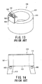
- a cryogenic refrigerator 102 and a current lead terminal 103 and the like that exist on a cylindrical cryostat 101 are arranged together on a refrigerator port 104 so as to avoid the interference with the pulling apparatus main body.
- Patent Document 2 Japanese Patent Laid-Open Publication No. 2000-114028
- a cryogenic refrigerator 102 and a current lead terminal 103 are mounted on a lower end face 112 of a cylindrical cryostat 101 in a manner such that an upper end face 111 of the cryostat 101 forms completely flat surface.
- Patent Document 3 Japanese Patent Laid-Open Publication No. 11-199366
- Patent Document 3 also discloses a superconducting magnet device for a single crystal pulling apparatus of the same kind as that disclosed in Patent Document 2.
- the aforementioned superconducting magnet device for a single crystal pulling apparatus 110 disclosed in the Patent Document 2 is superior with respect to interference with the pulling apparatus main body at the upper end face 111 of the cryostat 101 as well as the workability and safeness in working of the operator.
- the cryogenic refrigerator 102 requires periodical maintenance, and it is necessary to secure a maintenance space of 800 mm or more in the vertical direction from the installation surface in order to withdraw the refrigerator. Therefore, according to the superconducting magnet device 110 disclosed in the Patent Document 2 in which the cryogenic refrigerator 102 is inserted from the lower end face 112 of the cryostat 101, leg portions 113 are provided to secure maintenance space on the lower end face 112.
- the superconducting magnet device for a single crystal pulling apparatus
- the superconducting magnet device is raised and lowered in the vertical direction in order to adjust the magnetic field that is applied thereto. Therefore, if the overall height dimensions of the apparatus are large, the margin for adjustment of the magnetic field decreases.
- JP 11 176630 (A ) discloses a superconduction magnet system which can reduce a leak magnetic field in a magnet by avoiding evaporation of liquid helium when a static magnetic field is quenched.
- US 2005/0166600 A1 discloses a superconducting magnet apparatus including superconducting coils in a vacuum vessel.
- the vacuum vessel is provided with a refrigerator for cooling the superconducting coils.
- DE 103 24 674 A1 discloses a crystal pulling device having a cylindrical vacuum container containing a plurality of superconducting coils.
- EP 0 843 028 A1 discloses a magnetic-field applied crystal growth system comprising at least one growing furnace, a pulling device and a magnetic field generator.
- the magnetic field generator comprises a plurality of magnet units.
- EP 1 293 993 A2 discloses a superconducting magnet and a magnetic resonance imaging apparatus.
- US 2003/0112106 A1 discloses a super conducting magnet and a magnetic resonance imaging apparatus.
- JP 56 070614 (A ) discloses a current supply device for a superconductive coil.
- JP H 107486 discloses a single crystal production apparatus comprising a single-crystal pulling section and a magnetic field generator section for providing a magnetic field for a fusion section for a single crystal material in such a configuration that on both sides of the crystal pulling section a pair of main coils and a pair of subsidiary coils are provided.
- a crucible filled with a single crystal fusion material is heated by heaters so as to be maintained constantly in fused condition.
- a seed crystal is pulled up at a constant speed.
- the superconductive main coils and subsidiary coils generate a magnetic field in a vertical direction in the crucible. As a result, the heat convection induced by the heater is substantially controlled by magnetic resistance caused by the magnetic field in the vertical direction.
- the present invention has been made in consideration of the circumstances described above, and an object of the present invention is to provide a superconducting magnet device for a single crystal pulling apparatus that can suppress interference with a pulling apparatus and enhance workability and safeness in working of an operator on the apparatus, in addition to securing of a margin for adjusting an applied magnetic field.
- the cryogenic refrigerator may include a drive motor, and the drive motor is arranged in a magnetic field region in which modulation is not induced by a magnetic field generated by the superconducting coil inside the cryostat.
- the refrigerator port may be arranged at a plurality of locations on the outer surface of the cryostat. In such case, the refrigerator ports may also be continuously arranged on the outer surface of the cryostat.
- cryostat is a cylinder-shaped cylindrical cryostat.
- the superconducting coil inside the cryostat may be cooled to a cryogenic temperature by the cryogenic refrigerator via a heat transfer plate, or immersed in liquid helium that is filled in a coolant container inside the cryostat so as to be cooled to a cryogenic temperature by the cryogenic refrigerator.
- the superconducting coil inside the cryostat is immersed in liquid helium that is filled in a coolant container inside the cryostat so as to be cooled to a cryogenic temperature by the cryogenic refrigerator.
- the superconducting coil may also be a pair of saddle-shaped superconducting coils, or a pair or a plurality of pairs of circular superconducting coils.
- the refrigerator port including a cryogenic refrigerator is arranged on an outer surface of a cryostat, the upper end face of the cryostat is made to be flat.
- a protruding portion such as a leg portion does not exist on a lower end face of the cryostat, and it is hence possible to set the entire height dimensions of the apparatus to a low level. Accordingly, a margin for adjusting a magnetic field that adjusts an applied magnetic field by raising and lowering the apparatus can be favorably secured.
- a single crystal pulling apparatus 11 includes a superconducting magnet device 10, which is disposed outside a pulling furnace 13 which contains a crucible 12 for melting a semiconductor single crystal material 1, and the so-called MCZ method (magnetic-field-applied Czochralski method) is applied to the single crystal pulling apparatus 11 by applying a unidirectional transverse magnetic field (indicated by lines of magnetic force 2 in Fig. 1 ) to the single crystal material 1 melted inside the crucible 12 to thereby prevent convection of the melted single crystal material 1 inside the crucible 12.
- MCZ method magnetic-field-applied Czochralski method
- the crucible 12 is contained in the pulling furnace 13 having an upper opening upper region, and a heater 14 for heating and melting the single crystal material 1 disposed inside the crucible 12 is arranged between the pulling furnace 13 and the crucible 12.
- the superconducting magnet device 10 provided with a pair of superconducting coils 15 ( Fig. 3 ) is arranged outside the pulling furnace 13.
- a pulling machine for pulling up a single crystal ingot 3 (described later) along a center line O of the crucible 12 is provided at the upper portion of the pulling furnace 13.
- the single crystal material 1 is first introduced into the crucible 12 and heated by the heater 14 so as to melt the single crystal material 1.
- a seed crystal not shown, is downwardly inserted, for example, from an upper portion of the central portion of the crucible 12 into the melted single crystal material 1.
- the seed crystal is then pulled up in a pulling direction ⁇ at a predetermined speed by the pulling machine. In this manner, a crystal is grown in a boundary layer between a solid substance and a liquid substance to thereby generate the single crystal ingot 3.
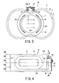
- the superconducting magnet device 10 includes a cryostat 17 that contains the superconducting coils 15 and radiation shields 16, and a single refrigerator port 19 that is arranged on an outer circumferential surface 18 of the cryostat 17 and includes a cryogenic refrigerator 20, a current lead terminal 23 and a valve, not shown.
- the cryostat 17 is a cylindrical cryostat. A vacuum condition is maintained inside the cryostat 17 for thermal insulation.
- the radiation shield 16 covers the superconducting coils 15, respectively, inside the cryostat 17, and blocks heat radiation to the superconducting coils 15 from the outside of the cryostat 17.
- the superconducting coils 15 are a pair of saddle-shaped coils that are arranged facing each other through a bore portion 24 in the cryostat 17.
- the superconducting coils 15 generate transverse magnetic fields in the same (one) direction (represented by lines of magnetic force 2 in Fig. 3 ) inside the bore portion 24 of the cryostat 17.
- the pulling furnace 13 and the crucible 12 are arranged inside the bore portion 24 of the cryostat 17.
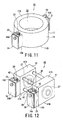
- the superconducting coils that are enclosed by the cryostat 17 are not limited to saddle-shaped coils like the superconducting coils 15, and there may be adopted a pair of circular superconducting coils 27 that are disposed so as to face each other through the bore portion 24 of the cryostat 17 as shown in Fig. 7 and Fig. 8 .
- the superconducting coils inside the cryostat 17 may be a plurality of pairs (for example, two pairs) of superconducting coils 28A and 28B disposed so as to face each other, respectively, through the bore portion 24 of the cryostat 17 as shown in Fig. 9 and Fig. 10 .
- Transverse magnetic fields in the same (one) direction are also generated inside the bore portion 24 of the cryostat 17 by the pair of superconducting coils 27 and the multiple pairs of superconducting coils 28A and 28B.
- a first cooling stage 21 is connected to the radiation shield 16 via a heat transfer plate 25.
- the radiation shield 16 is, for example, cooled to a cryogenic temperature around 40 K.
- a second cooling stage 22 is connected via a heat transfer plate 26 to superconducting coils 15, 27, or 28A and 28B.
- the superconducting coils 15, 27, or 28A and 28B are, for example, cooled to a cryogenic temperature around 4K.
- One or a plurality of the cryogenic refrigerators 20 is arranged on the refrigerator port 19 (a plurality (two) of the cryogenic refrigerators 20 is shown in Fig. 2 ).
- the current lead terminal 23 supplies a current to the superconducting coils 15, 27, or 28A and 28B.
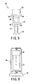
- the cryogenic refrigerator 20 is a common type of refrigerator, in which the second cooling stage 22 is arranged below the first cooling stage 21, and a drive motor 33 is arranged at an uppermost portion.
- a first displacer (first cold accumulating unit) 35 is housed inside a first cylinder 34 that has the first cooling stage 21 provided at the lower end thereof
- a second displacer (second cold accumulating unit) 37 is housed inside a second cylinder 36 that has the second cooling stage 22 provided at the lower end thereof.
- the first displacer 35 and the second displacer 37 are moved reciprocally in the longitudinal direction (in this case, the vertical direction) of the respective cylinders.
- a working fluid for example, He gas
- a working fluid that is introduced between the lower end of the first cylinder 34 and the first displacer 35 and between the lower end of the second cylinder 36 and the second displacer 37, respectively, undergoes adiabatic expansion to obtain a predetermined refrigerating capacity.
- the refrigerator port 19 is arranged on the outer circumferential surface 18 of the cryostat 17 in an area between an upper end face 17A and a lower end face 17B of the cryostat 17. Further, the cryogenic refrigerator 20, the current lead terminal 23, the valve and the like that are mounted on the refrigerator port 19 are arranged within the aforementioned area between the upper end face 17A and the lower end face 17B of the cryostat 17.
- cryogenic refrigerator 20, the current lead terminal 23, and the valve and the like are inserted from an upper end face 19A side or lower end face 19B side of the refrigerator port 19 so as to be mounted thereon, portions that are exposed from the upper end face 19A and lower end face 19B at this time are arranged within an area between the upper end face 17A and lower end face 17B of the cryostat 17.
- the refrigerator port 19 and exposed portions such as the cryogenic refrigerator 20, the current lead terminal 23, and the valve are prevented from protruding from the upper end face 17A and lower end face 17B of the cryostat 17.
- the refrigerator port 19 is arranged in a magnetic field region in which modulation at the drive motor 33 ( Fig. 5 ) of the cryogenic refrigerator 20 is not induced by a magnetic field generated by the superconducting coils 15, 27, or 28A and 28B. More specifically, in Fig. 3 , Fig. 7 and Fig. 9 , a reference character "X" denotes a boundary at which the intensity of the magnetic field is between 40 and 50 mT (millitesla).
- the refrigerator port 19, and particularly, the cryogenic refrigerator 20 mounted on the refrigerator port 19, is arranged in a magnetic field region W (region on the outer side of the boundary X) in which the intensity of the magnetic field is less than 40 to 50 mT. Consequently, the occurrence of modulation (including stopping) at the drive motor 33 of the cryogenic refrigerator 20 is avoided.
- the cryogenic refrigerator 20 is provided in a region of the outer surface region of the cryostat 17 at which the intensity of a magnetic field generated by the superconducting coils 15 is weak. More specifically, the intensity of a magnetic field generated by the superconducting coils 15 disposed inside the cryostat 17 is weaker in the region of the outer surface of the cryostat 17 at which the cryogenic refrigerator 20 is provided than in other regions of the outer surface of the cryostat 17.
- the boundary "X" at which the magnetic field intensity is between 40 and 50 mT as shown in Fig. 3 , Fig. 7 and Fig. 9 is the intensity of a magnetic field at a central plane 29A at a central position in an axial direction (vertical direction) in the superconducting magnet device 10 shown in Fig. 4 , Fig. 8 and Fig. 10 .
- a reference character "Y" in Fig. 3 , Fig. 7 and Fig. 9a denotes a boundary of an intensity of a magnetic field equivalent to the boundary X at planes 29B and 29C between the central plane 29A and the upper end face 17A and lower end face 17B of the cryostat 17, respectively, in the superconducting magnet device 10.
- a reference character "Z” in Fig. 3 , Fig. 7 and Fig. 9a denotes a boundary of an intensity of a magnetic field equivalent to the aforementioned boundary "X" at planes 29D and 29E that include the upper end face 17A and lower end face 17B of the cryostat 17, respectively.
- the intensities (for example, 40 to 50 mT) of equivalent magnetic fields have a similar shape on each plane in the vertical direction, and the magnetic field intensities decrease as the relevant planes are separated from the central plane 29A in the axial direction (vertical direction) of the superconducting magnet device 10.
- the cryogenic refrigerator 20 is arranged outside (in magnetic field region W) the boundary "X" for which the magnetic field intensity is largest among the intensities between 40 and 50 mT, and therefore, is not exposed to a magnetic field with an intensity between 40 and 50 mT or more.
- the seal portions 38 and 39 arranged at the upper portion of the first displacer 35 and the second displacer 37, respectively, do not press against one side of the inner circumferential surface of the first cylinder 34 and the second cylinder 36, respectively, so that the sealing property thereof is favorably maintained.
- the refrigerating capacity can be suitably maintained and it is further possible to prevent an overload in the drive motor 33 due to the friction or the like, and also prevent the first displacer 35, the second displacer 37 and the seal portions 38 and 39 from damaging.
- the operating life and reliability of the cryogenic refrigerator 20 can be enhanced.
- the first displacer 35 and the second displacer 37 have a thermal gradient such that, in an operating state, the upper end in the axial direction (vertical direction) thereof becomes a high temperature end and the lower end becomes a low temperature end.
- a working fluid (He gas or the like) that is introduced inside the first cylinder 34 and the second cylinder 36 similarly has a thermal gradient in the vertical direction such that the upper portion becomes a high temperature and the lower portion becomes a low temperature due to a density difference caused by the temperature.
- the direction of the aforementioned thermal gradient of the first displacer 35 and the second displacer 37 matches the direction of the thermal gradient of the working fluid. Hence, a heat exchange effect can be favorably maintained, and the refrigerating capacity of the cryogenic refrigerator 20 can be suitably ensured.
- the cryogenic refrigerator 20 is a type in which the first displacer 35 and the second displacer 37 perform a reciprocating movement in the vertical direction inside the first cylinder 34 and the second cylinder 36, respectively.
- the first displacer 35 and the second displacer 37 can be inserted concentrically with high precision into the first cylinder 34 and the second cylinder 36, respectively. Consequently, the workability of the maintenance operation can be enhanced and damage, which may be caused by a collision involving the first displacer 35, the second displacer 37, the first cylinder 34 or the second cylinder 36, can be prevented.
- Fig. 11 is a perspective view that represents a second embodiment of the superconducting magnet device for a single crystal pulling apparatus according to the present invention.
- like reference numerals are added to portions or components similar to the first embodiment and the duplicated description thereof is simplified or omitted herein.
- a superconducting magnet device for a single crystal pulling apparatus 30 of the present embodiment differs from the superconducting magnet device 10 of the first embodiment in the point that a plurality of the refrigerator ports 31 are arranged in a dispersed manner on the outer circumferential surface 18 of the cryostat 17. Further, one or a plurality of (one according to the present embodiment) the cryogenic refrigerator 20 is mounted on each refrigerator port 31.
- this embodiment is one in which a plurality of the refrigerator ports shown in Fig. 2 are provided, as shown in Fig. 11 .
- a superconducting magnet device for a single crystal pulling apparatus of the present third embodiment differs from the superconducting magnet devices 10 and 30 according to the first and second embodiments in the point that the refrigerator ports on which a plurality of the cryogenic refrigerators 20 are mounted are continuously arranged in an annular shape on the outer circumferential surface 18 of the cryostat 17. More specifically, the third embodiment is one in which a plurality of the refrigerator ports 19 shown in Fig. 2 are arranged on an outer circumferential surface of the cryostat 17 as shown in Fig. 11 .
- Fig. 12 is a perspective view that represents another example of a superconducting magnet device for a single crystal pulling apparatus.
- like reference numerals are added to portions or components similar to those of the first embodiment, and the duplicated description thereof is simplified or omitted herein.
- a superconducting magnet device for a single crystal pulling apparatus 40 of the present example differs from the superconducting magnet device 10 of the first embodiment in the point that the refrigerator port 19, on which the cryogenic refrigerator 20, the current lead terminal 23, and the valve are mounted, is arranged on an outer surface 42 of a split-type cryostat 41 having a rectangular parallelepiped shape.
- a plurality of the split-type cryostats 41 are arranged facing each other, and an interval between the respectively adjacent cryostats 41 is linked by adjustable support members 43.
- a superconducting coil 27 and a radiation shield 16 are enclosed inside each cryostat 41.
- the superconducting coil 27 and the radiation shield 16 are cooled to a cryogenic temperature by the cryogenic refrigerator 20.
- a unidirectional transverse magnetic field is generated by the superconducting coils 27 between the cryostats 41.
- the unidirectional transverse magnetic field is generated by the superconducting coils 27 between the cryostats 41.
- the transverse magnetic field is applied to the pulling furnace 13 and the crucible 12 of the single crystal pulling apparatus 11 arranged between the cryostats 41.
- the refrigerator port 19 is arranged on the outer surface 42 of each cryostat 41 so as to be within an area between the upper end face 41A and lower end face 41B of the cryostat 41. Further, exposed portions such as the cryogenic refrigerator 20, the current lead terminal 23 and the valve are arranged on the refrigerator port 19 so as to be within an area between the upper end face 41A and lower end face 41B of the cryostat 41. Furthermore, the refrigerator port 19 is arranged in a magnetic field region in which modulation at a drive motor of the cryogenic refrigerator 20 is not induced by a magnetic field generated by the superconducting coil 27 inside the cryostat 41.
- the present invention has been described in the hereinabove with reference to the embodiments, it is to be understood that the present invention is not limited to the above embodiments.
- a conduction cooling system in which the superconducting coils 15, 27, or 28 inside the cryostat 17 or 41 are cooled to a cryogenic temperature by the cryogenic refrigerator 20 via the heat transfer plate 26.
- an immersion cooling system in which the superconducting coils 15, 27, or 28 are immersed in liquid helium that is filled in a coolant container inside the cryostat 17 or 41, and cooled to a cryogenic temperature by the cryogenic refrigerator 20.
Landscapes
- Engineering & Computer Science (AREA)
- Chemical & Material Sciences (AREA)
- Power Engineering (AREA)
- Crystallography & Structural Chemistry (AREA)
- Materials Engineering (AREA)
- Metallurgy (AREA)
- Organic Chemistry (AREA)
- Crystals, And After-Treatments Of Crystals (AREA)
- Containers, Films, And Cooling For Superconductive Devices (AREA)
Applications Claiming Priority (3)
| Application Number | Priority Date | Filing Date | Title |
|---|---|---|---|
| JP2008136515 | 2008-05-26 | ||
| JP2009100618A JP5889509B2 (ja) | 2008-05-26 | 2009-04-17 | 単結晶引上げ装置用超電導マグネット装置 |
| PCT/JP2009/059539 WO2009145149A1 (ja) | 2008-05-26 | 2009-05-25 | 単結晶引上げ装置用超電導マグネット装置 |
Publications (3)
| Publication Number | Publication Date |
|---|---|
| EP2287366A1 EP2287366A1 (en) | 2011-02-23 |
| EP2287366A4 EP2287366A4 (en) | 2012-11-21 |
| EP2287366B1 true EP2287366B1 (en) | 2016-01-06 |
Family
ID=41377022
Family Applications (1)
| Application Number | Title | Priority Date | Filing Date |
|---|---|---|---|
| EP09754657.6A Active EP2287366B1 (en) | 2008-05-26 | 2009-05-25 | Superconducting magnet device for single crystal puller |
Country Status (4)
| Country | Link |
|---|---|
| US (1) | US8280468B2 (ja) |
| EP (1) | EP2287366B1 (ja) |
| JP (1) | JP5889509B2 (ja) |
| WO (1) | WO2009145149A1 (ja) |
Families Citing this family (12)
| Publication number | Priority date | Publication date | Assignee | Title |
|---|---|---|---|---|
| CN103106994B (zh) * | 2013-01-29 | 2015-08-26 | 西部超导材料科技股份有限公司 | 一种用于磁控直拉单晶的MgB2超导绕组装置 |
| CN110129883A (zh) * | 2018-03-30 | 2019-08-16 | 杭州慧翔电液技术开发有限公司 | 一种用于磁控直拉单晶的磁体结构及磁控直拉单晶的方法 |
| CN110136915A (zh) * | 2019-06-10 | 2019-08-16 | 杭州慧翔电液技术开发有限公司 | 一种超导磁体和磁控直拉单晶设备 |
| CN111009375A (zh) * | 2019-12-19 | 2020-04-14 | 西部超导材料科技股份有限公司 | 一种传导冷却磁控拉单晶超导磁体装置 |
| CN110957101A (zh) * | 2019-12-19 | 2020-04-03 | 西部超导材料科技股份有限公司 | 一种传导冷却闭环马鞍形磁控拉单晶超导磁体装置 |
| KR102837217B1 (ko) * | 2020-03-17 | 2025-07-22 | 신에쯔 한도타이 가부시키가이샤 | 단결정 인상장치 및 단결정 인상방법 |
| US20230247795A1 (en) | 2022-01-28 | 2023-08-03 | The Research Foundation For The State University Of New York | Regenerative preheater for phase change cooling applications |
| CN115289716A (zh) * | 2022-06-09 | 2022-11-04 | 北京交通大学 | 一种双极冷头制冷机冷插拔装置 |
| US12486593B2 (en) | 2022-08-29 | 2025-12-02 | Globalwafers Co., Ltd. | Axial positioning of magnetic poles while producing a silicon ingot |
| US12486594B2 (en) | 2022-08-29 | 2025-12-02 | Globalwafers Co., Ltd. | Ingot puller apparatus that axially position magnetic poles |
| JP2025047650A (ja) * | 2023-09-21 | 2025-04-03 | 住友重機械工業株式会社 | 超伝導磁石装置 |
| CN119332336B (zh) * | 2024-11-07 | 2025-06-10 | 连城凯克斯科技有限公司 | 一种磁控直拉单晶装置 |
Citations (1)
| Publication number | Priority date | Publication date | Assignee | Title |
|---|---|---|---|---|
| JPH107486A (ja) * | 1996-06-20 | 1998-01-13 | Mitsubishi Electric Corp | 磁界印加式単結晶製造装置 |
Family Cites Families (19)
| Publication number | Priority date | Publication date | Assignee | Title |
|---|---|---|---|---|
| JPS5670614A (en) * | 1979-11-15 | 1981-06-12 | Toshiba Corp | Current supply device |
| US4565671A (en) * | 1983-08-05 | 1986-01-21 | Kabushiki Kaisha Toshiba | Single crystal manufacturing apparatus |
| US5410286A (en) * | 1994-02-25 | 1995-04-25 | General Electric Company | Quench-protected, refrigerated superconducting magnet |
| JPH09326513A (ja) * | 1996-04-05 | 1997-12-16 | Nippon Steel Corp | 磁気シールド体および超電導マグネット装置 |
| US6011810A (en) * | 1996-04-23 | 2000-01-04 | The Regents Of The University Of California | Doping of germanium and silicon crystals with non-hydrogenic acceptors for far infrared lasers |
| JPH10120485A (ja) * | 1996-10-18 | 1998-05-12 | Mitsubishi Steel Mfg Co Ltd | 単結晶製造装置 |
| JP3592467B2 (ja) * | 1996-11-14 | 2004-11-24 | 株式会社東芝 | 単結晶引上げ装置用超電導磁石 |
| JPH11176630A (ja) * | 1997-12-08 | 1999-07-02 | Toshiba Corp | 単結晶育成用超電導磁石システム |
| JP3833382B2 (ja) * | 1998-01-14 | 2006-10-11 | 住友重機械工業株式会社 | 単結晶引上げ装置用の冷凍機冷却型超電導磁石装置 |
| JPH11199366A (ja) * | 1998-01-20 | 1999-07-27 | Mitsubishi Electric Corp | 単結晶シリコン引き上げ装置 |
| JP2000095597A (ja) * | 1998-09-25 | 2000-04-04 | Toshiba Ceramics Co Ltd | 単結晶引上装置 |
| JP3421837B2 (ja) | 1998-10-08 | 2003-06-30 | 住友重機械工業株式会社 | 単結晶引上げ装置用の冷凍機冷却型超電導磁石装置 |
| US6667676B2 (en) * | 2001-09-12 | 2003-12-23 | Hitachi, Ltd. | Superconducting magnet and magnetic resonance imaging apparatus using the same |
| US6664876B2 (en) * | 2001-09-12 | 2003-12-16 | Hitachi, Ltd. | Superconducting magnet and magnetic resonance imaging apparatus using the same |
| JP2004051475A (ja) * | 2002-05-31 | 2004-02-19 | Toshiba Corp | 単結晶引上げ装置、超電導磁石および単結晶引上げ方法 |
| JP4345276B2 (ja) * | 2002-08-30 | 2009-10-14 | 株式会社Sumco | 磁場印加式シリコン単結晶の引上げ方法 |
| JP4157424B2 (ja) * | 2003-05-22 | 2008-10-01 | 住友重機械工業株式会社 | 冷凍機冷却型超電導マグネット装置 |
| JP4749661B2 (ja) | 2003-10-15 | 2011-08-17 | 住友重機械工業株式会社 | 単結晶引上げ装置用超電導磁石装置における冷凍機の装着構造及び冷凍機のメンテナンス方法 |
| JP2005185550A (ja) * | 2003-12-25 | 2005-07-14 | Mitsubishi Electric Corp | 磁石装置及び磁気共鳴イメ−ジング装置 |
-
2009
- 2009-04-17 JP JP2009100618A patent/JP5889509B2/ja active Active
- 2009-05-25 WO PCT/JP2009/059539 patent/WO2009145149A1/ja not_active Ceased
- 2009-05-25 EP EP09754657.6A patent/EP2287366B1/en active Active
- 2009-05-25 US US12/994,838 patent/US8280468B2/en active Active
Patent Citations (1)
| Publication number | Priority date | Publication date | Assignee | Title |
|---|---|---|---|---|
| JPH107486A (ja) * | 1996-06-20 | 1998-01-13 | Mitsubishi Electric Corp | 磁界印加式単結晶製造装置 |
Also Published As
| Publication number | Publication date |
|---|---|
| EP2287366A4 (en) | 2012-11-21 |
| US8280468B2 (en) | 2012-10-02 |
| JP5889509B2 (ja) | 2016-03-22 |
| JP2010006687A (ja) | 2010-01-14 |
| EP2287366A1 (en) | 2011-02-23 |
| WO2009145149A1 (ja) | 2009-12-03 |
| US20110077161A1 (en) | 2011-03-31 |
Similar Documents
| Publication | Publication Date | Title |
|---|---|---|
| EP2287366B1 (en) | Superconducting magnet device for single crystal puller | |
| CN101118798B (zh) | 超导磁铁装置以及磁共振成像装置 | |
| KR100508210B1 (ko) | 단결정 인상장치용 초전도 자석장치에 있어서의 냉동기의장착구조 및 냉동기의 유지보수 방법 | |
| US11578423B2 (en) | Magnet coil for magnetic czochralski single crystal growth and magnetic czochralski single crystal growth method | |
| JP4031121B2 (ja) | クライオスタット装置 | |
| KR100562260B1 (ko) | 단결정 인상 장치, 단결정 인상 방법 및 초전도 자석 | |
| RU2746111C1 (ru) | Камера для литья в оболочковые формы, литейная печь и способ монокристаллического, мелкокристаллического и некристаллического литья | |
| CN110136915A (zh) | 一种超导磁体和磁控直拉单晶设备 | |
| JP2020522457A (ja) | 単結晶の磁場印加引き上げに用いられる磁性体、および単結晶の磁場印加引き上げ方法 | |
| KR20140044544A (ko) | 단결정 성장장치 및 성장방법 | |
| CN116798724A (zh) | 一种超导磁体、磁控拉单晶设备及控制方法 | |
| KR0176328B1 (ko) | 축방향 자기장을 인가할 수 있는 수직온도 구배냉각 및 수직브릿지만 화합물 반도체 단결정 성장장치 | |
| JP3592467B2 (ja) | 単結晶引上げ装置用超電導磁石 | |
| JP3535312B2 (ja) | 磁界印加式単結晶製造装置 | |
| US6482261B2 (en) | Magnetic field furnace | |
| JP7230781B2 (ja) | 単結晶引き上げ装置及び単結晶引き上げ方法 | |
| JPH10316488A (ja) | 磁界印加方式の単結晶製造装置 | |
| JPH11176630A (ja) | 単結晶育成用超電導磁石システム | |
| JP5920924B2 (ja) | 超電導磁石装置及び磁気共鳴撮像装置 | |
| JP3585731B2 (ja) | 磁界印加式単結晶製造装置 | |
| JP2000312036A (ja) | 低温容器内に配置される重量構造物の支持構造 | |
| AU2002246865A1 (en) | Magnetic field furnace and a method of using the same to manufacture semiconductor substrates | |
| JP2013193946A (ja) | 超電導装置 | |
| JPH08333190A (ja) | 単結晶引上装置 | |
| WO2024248907A1 (en) | Asymmetric thermal fields for excluding impurities in single crystal manufacturing device |
Legal Events
| Date | Code | Title | Description |
|---|---|---|---|
| PUAI | Public reference made under article 153(3) epc to a published international application that has entered the european phase |
Free format text: ORIGINAL CODE: 0009012 |
|
| 17P | Request for examination filed |
Effective date: 20101126 |
|
| AK | Designated contracting states |
Kind code of ref document: A1 Designated state(s): AT BE BG CH CY CZ DE DK EE ES FI FR GB GR HR HU IE IS IT LI LT LU LV MC MK MT NL NO PL PT RO SE SI SK TR |
|
| AX | Request for extension of the european patent |
Extension state: AL BA RS |
|
| RIN1 | Information on inventor provided before grant (corrected) |
Inventor name: USHIJIMA ,MAKOTO Inventor name: MINEMOTO,YUUJI Inventor name: SHIMONOSONO,TSUTOMU Inventor name: TAKAMI SHOHEI Inventor name: NAGAMOTO,YOSHIFUMI Inventor name: OTA,TOMOKO |
|
| DAX | Request for extension of the european patent (deleted) | ||
| REG | Reference to a national code |
Ref country code: DE Ref legal event code: R079 Ref document number: 602009035629 Country of ref document: DE Free format text: PREVIOUS MAIN CLASS: C30B0015000000 Ipc: H01F0006040000 |
|
| A4 | Supplementary search report drawn up and despatched |
Effective date: 20121023 |
|
| RIC1 | Information provided on ipc code assigned before grant |
Ipc: C30B 15/30 20060101ALI20121016BHEP Ipc: H01F 6/04 20060101AFI20121016BHEP |
|
| 17Q | First examination report despatched |
Effective date: 20140224 |
|
| GRAP | Despatch of communication of intention to grant a patent |
Free format text: ORIGINAL CODE: EPIDOSNIGR1 |
|
| INTG | Intention to grant announced |
Effective date: 20150714 |
|
| RIN1 | Information on inventor provided before grant (corrected) |
Inventor name: OTA, TOMOKO Inventor name: SHIMONOSONO, TSUTOMU Inventor name: MINEMOTO, YUUJI Inventor name: USHIJIMA, MAKOTO Inventor name: TAKAMI, SHOHEI Inventor name: NAGAMOTO, YOSHIFUMI |
|
| GRAS | Grant fee paid |
Free format text: ORIGINAL CODE: EPIDOSNIGR3 |
|
| GRAA | (expected) grant |
Free format text: ORIGINAL CODE: 0009210 |
|
| AK | Designated contracting states |
Kind code of ref document: B1 Designated state(s): AT BE BG CH CY CZ DE DK EE ES FI FR GB GR HR HU IE IS IT LI LT LU LV MC MK MT NL NO PL PT RO SE SI SK TR |
|
| REG | Reference to a national code |
Ref country code: GB Ref legal event code: FG4D |
|
| REG | Reference to a national code |
Ref country code: CH Ref legal event code: EP |
|
| REG | Reference to a national code |
Ref country code: IE Ref legal event code: FG4D |
|
| REG | Reference to a national code |
Ref country code: AT Ref legal event code: REF Ref document number: 769473 Country of ref document: AT Kind code of ref document: T Effective date: 20160215 |
|
| REG | Reference to a national code |
Ref country code: DE Ref legal event code: R096 Ref document number: 602009035629 Country of ref document: DE |
|
| REG | Reference to a national code |
Ref country code: LT Ref legal event code: MG4D |
|
| REG | Reference to a national code |
Ref country code: NL Ref legal event code: MP Effective date: 20160106 |
|
| REG | Reference to a national code |
Ref country code: AT Ref legal event code: MK05 Ref document number: 769473 Country of ref document: AT Kind code of ref document: T Effective date: 20160106 |
|
| PG25 | Lapsed in a contracting state [announced via postgrant information from national office to epo] |
Ref country code: NL Free format text: LAPSE BECAUSE OF FAILURE TO SUBMIT A TRANSLATION OF THE DESCRIPTION OR TO PAY THE FEE WITHIN THE PRESCRIBED TIME-LIMIT Effective date: 20160106 |
|
| PG25 | Lapsed in a contracting state [announced via postgrant information from national office to epo] |
Ref country code: GR Free format text: LAPSE BECAUSE OF FAILURE TO SUBMIT A TRANSLATION OF THE DESCRIPTION OR TO PAY THE FEE WITHIN THE PRESCRIBED TIME-LIMIT Effective date: 20160407 Ref country code: FI Free format text: LAPSE BECAUSE OF FAILURE TO SUBMIT A TRANSLATION OF THE DESCRIPTION OR TO PAY THE FEE WITHIN THE PRESCRIBED TIME-LIMIT Effective date: 20160106 Ref country code: HR Free format text: LAPSE BECAUSE OF FAILURE TO SUBMIT A TRANSLATION OF THE DESCRIPTION OR TO PAY THE FEE WITHIN THE PRESCRIBED TIME-LIMIT Effective date: 20160106 Ref country code: IT Free format text: LAPSE BECAUSE OF FAILURE TO SUBMIT A TRANSLATION OF THE DESCRIPTION OR TO PAY THE FEE WITHIN THE PRESCRIBED TIME-LIMIT Effective date: 20160106 Ref country code: ES Free format text: LAPSE BECAUSE OF FAILURE TO SUBMIT A TRANSLATION OF THE DESCRIPTION OR TO PAY THE FEE WITHIN THE PRESCRIBED TIME-LIMIT Effective date: 20160106 Ref country code: NO Free format text: LAPSE BECAUSE OF FAILURE TO SUBMIT A TRANSLATION OF THE DESCRIPTION OR TO PAY THE FEE WITHIN THE PRESCRIBED TIME-LIMIT Effective date: 20160406 |
|
| PG25 | Lapsed in a contracting state [announced via postgrant information from national office to epo] |
Ref country code: IS Free format text: LAPSE BECAUSE OF FAILURE TO SUBMIT A TRANSLATION OF THE DESCRIPTION OR TO PAY THE FEE WITHIN THE PRESCRIBED TIME-LIMIT Effective date: 20160506 Ref country code: PT Free format text: LAPSE BECAUSE OF FAILURE TO SUBMIT A TRANSLATION OF THE DESCRIPTION OR TO PAY THE FEE WITHIN THE PRESCRIBED TIME-LIMIT Effective date: 20160506 Ref country code: SE Free format text: LAPSE BECAUSE OF FAILURE TO SUBMIT A TRANSLATION OF THE DESCRIPTION OR TO PAY THE FEE WITHIN THE PRESCRIBED TIME-LIMIT Effective date: 20160106 Ref country code: PL Free format text: LAPSE BECAUSE OF FAILURE TO SUBMIT A TRANSLATION OF THE DESCRIPTION OR TO PAY THE FEE WITHIN THE PRESCRIBED TIME-LIMIT Effective date: 20160106 Ref country code: LT Free format text: LAPSE BECAUSE OF FAILURE TO SUBMIT A TRANSLATION OF THE DESCRIPTION OR TO PAY THE FEE WITHIN THE PRESCRIBED TIME-LIMIT Effective date: 20160106 Ref country code: AT Free format text: LAPSE BECAUSE OF FAILURE TO SUBMIT A TRANSLATION OF THE DESCRIPTION OR TO PAY THE FEE WITHIN THE PRESCRIBED TIME-LIMIT Effective date: 20160106 Ref country code: BE Free format text: LAPSE BECAUSE OF NON-PAYMENT OF DUE FEES Effective date: 20160531 Ref country code: LV Free format text: LAPSE BECAUSE OF FAILURE TO SUBMIT A TRANSLATION OF THE DESCRIPTION OR TO PAY THE FEE WITHIN THE PRESCRIBED TIME-LIMIT Effective date: 20160106 |
|
| REG | Reference to a national code |
Ref country code: DE Ref legal event code: R097 Ref document number: 602009035629 Country of ref document: DE |
|
| PG25 | Lapsed in a contracting state [announced via postgrant information from national office to epo] |
Ref country code: EE Free format text: LAPSE BECAUSE OF FAILURE TO SUBMIT A TRANSLATION OF THE DESCRIPTION OR TO PAY THE FEE WITHIN THE PRESCRIBED TIME-LIMIT Effective date: 20160106 Ref country code: DK Free format text: LAPSE BECAUSE OF FAILURE TO SUBMIT A TRANSLATION OF THE DESCRIPTION OR TO PAY THE FEE WITHIN THE PRESCRIBED TIME-LIMIT Effective date: 20160106 |
|
| PLBE | No opposition filed within time limit |
Free format text: ORIGINAL CODE: 0009261 |
|
| STAA | Information on the status of an ep patent application or granted ep patent |
Free format text: STATUS: NO OPPOSITION FILED WITHIN TIME LIMIT |
|
| PG25 | Lapsed in a contracting state [announced via postgrant information from national office to epo] |
Ref country code: CZ Free format text: LAPSE BECAUSE OF FAILURE TO SUBMIT A TRANSLATION OF THE DESCRIPTION OR TO PAY THE FEE WITHIN THE PRESCRIBED TIME-LIMIT Effective date: 20160106 Ref country code: SK Free format text: LAPSE BECAUSE OF FAILURE TO SUBMIT A TRANSLATION OF THE DESCRIPTION OR TO PAY THE FEE WITHIN THE PRESCRIBED TIME-LIMIT Effective date: 20160106 Ref country code: RO Free format text: LAPSE BECAUSE OF FAILURE TO SUBMIT A TRANSLATION OF THE DESCRIPTION OR TO PAY THE FEE WITHIN THE PRESCRIBED TIME-LIMIT Effective date: 20160106 |
|
| 26N | No opposition filed |
Effective date: 20161007 |
|
| PG25 | Lapsed in a contracting state [announced via postgrant information from national office to epo] |
Ref country code: LU Free format text: LAPSE BECAUSE OF FAILURE TO SUBMIT A TRANSLATION OF THE DESCRIPTION OR TO PAY THE FEE WITHIN THE PRESCRIBED TIME-LIMIT Effective date: 20160525 Ref country code: BE Free format text: LAPSE BECAUSE OF FAILURE TO SUBMIT A TRANSLATION OF THE DESCRIPTION OR TO PAY THE FEE WITHIN THE PRESCRIBED TIME-LIMIT Effective date: 20160106 |
|
| REG | Reference to a national code |
Ref country code: CH Ref legal event code: PL |
|
| PG25 | Lapsed in a contracting state [announced via postgrant information from national office to epo] |
Ref country code: CH Free format text: LAPSE BECAUSE OF NON-PAYMENT OF DUE FEES Effective date: 20160531 Ref country code: LI Free format text: LAPSE BECAUSE OF NON-PAYMENT OF DUE FEES Effective date: 20160531 |
|
| REG | Reference to a national code |
Ref country code: IE Ref legal event code: MM4A |
|
| PG25 | Lapsed in a contracting state [announced via postgrant information from national office to epo] |
Ref country code: BG Free format text: LAPSE BECAUSE OF FAILURE TO SUBMIT A TRANSLATION OF THE DESCRIPTION OR TO PAY THE FEE WITHIN THE PRESCRIBED TIME-LIMIT Effective date: 20160406 Ref country code: SI Free format text: LAPSE BECAUSE OF FAILURE TO SUBMIT A TRANSLATION OF THE DESCRIPTION OR TO PAY THE FEE WITHIN THE PRESCRIBED TIME-LIMIT Effective date: 20160106 |
|
| REG | Reference to a national code |
Ref country code: FR Ref legal event code: ST Effective date: 20170131 |
|
| PG25 | Lapsed in a contracting state [announced via postgrant information from national office to epo] |
Ref country code: FR Free format text: LAPSE BECAUSE OF NON-PAYMENT OF DUE FEES Effective date: 20160531 |
|
| PG25 | Lapsed in a contracting state [announced via postgrant information from national office to epo] |
Ref country code: IE Free format text: LAPSE BECAUSE OF NON-PAYMENT OF DUE FEES Effective date: 20160525 |
|
| PG25 | Lapsed in a contracting state [announced via postgrant information from national office to epo] |
Ref country code: CY Free format text: LAPSE BECAUSE OF FAILURE TO SUBMIT A TRANSLATION OF THE DESCRIPTION OR TO PAY THE FEE WITHIN THE PRESCRIBED TIME-LIMIT Effective date: 20160106 Ref country code: HU Free format text: LAPSE BECAUSE OF FAILURE TO SUBMIT A TRANSLATION OF THE DESCRIPTION OR TO PAY THE FEE WITHIN THE PRESCRIBED TIME-LIMIT; INVALID AB INITIO Effective date: 20090525 |
|
| PG25 | Lapsed in a contracting state [announced via postgrant information from national office to epo] |
Ref country code: MT Free format text: LAPSE BECAUSE OF NON-PAYMENT OF DUE FEES Effective date: 20160531 Ref country code: MC Free format text: LAPSE BECAUSE OF FAILURE TO SUBMIT A TRANSLATION OF THE DESCRIPTION OR TO PAY THE FEE WITHIN THE PRESCRIBED TIME-LIMIT Effective date: 20160106 Ref country code: MK Free format text: LAPSE BECAUSE OF FAILURE TO SUBMIT A TRANSLATION OF THE DESCRIPTION OR TO PAY THE FEE WITHIN THE PRESCRIBED TIME-LIMIT Effective date: 20160106 Ref country code: TR Free format text: LAPSE BECAUSE OF FAILURE TO SUBMIT A TRANSLATION OF THE DESCRIPTION OR TO PAY THE FEE WITHIN THE PRESCRIBED TIME-LIMIT Effective date: 20160106 |
|
| PGFP | Annual fee paid to national office [announced via postgrant information from national office to epo] |
Ref country code: DE Payment date: 20250402 Year of fee payment: 17 |
|
| PGFP | Annual fee paid to national office [announced via postgrant information from national office to epo] |
Ref country code: GB Payment date: 20250401 Year of fee payment: 17 |