EP2286972A1 - Method for chamfering brittle material substrate - Google Patents
Method for chamfering brittle material substrate Download PDFInfo
- Publication number
- EP2286972A1 EP2286972A1 EP20090754534 EP09754534A EP2286972A1 EP 2286972 A1 EP2286972 A1 EP 2286972A1 EP 20090754534 EP20090754534 EP 20090754534 EP 09754534 A EP09754534 A EP 09754534A EP 2286972 A1 EP2286972 A1 EP 2286972A1
- Authority
- EP
- European Patent Office
- Prior art keywords
- brittle material
- material substrate
- substrate
- edge
- cutter wheel
- Prior art date
- Legal status (The legal status is an assumption and is not a legal conclusion. Google has not performed a legal analysis and makes no representation as to the accuracy of the status listed.)
- Withdrawn
Links
- 239000000758 substrate Substances 0.000 title claims abstract description 159
- 238000000034 method Methods 0.000 title claims abstract description 61
- 239000000463 material Substances 0.000 title claims abstract description 45
- 238000005520 cutting process Methods 0.000 claims abstract description 26
- 238000010438 heat treatment Methods 0.000 claims abstract description 9
- 238000001816 cooling Methods 0.000 claims abstract description 8
- 239000011521 glass Substances 0.000 claims description 53
- 230000002093 peripheral effect Effects 0.000 claims description 19
- 238000004140 cleaning Methods 0.000 abstract description 3
- 230000000052 comparative effect Effects 0.000 description 4
- 239000000843 powder Substances 0.000 description 3
- IJGRMHOSHXDMSA-UHFFFAOYSA-N Atomic nitrogen Chemical compound N#N IJGRMHOSHXDMSA-UHFFFAOYSA-N 0.000 description 2
- CURLTUGMZLYLDI-UHFFFAOYSA-N Carbon dioxide Chemical compound O=C=O CURLTUGMZLYLDI-UHFFFAOYSA-N 0.000 description 2
- 239000006063 cullet Substances 0.000 description 2
- 238000002438 flame photometric detection Methods 0.000 description 2
- 239000012634 fragment Substances 0.000 description 2
- 238000004519 manufacturing process Methods 0.000 description 2
- 238000000059 patterning Methods 0.000 description 2
- 230000015572 biosynthetic process Effects 0.000 description 1
- 229910002092 carbon dioxide Inorganic materials 0.000 description 1
- 239000001569 carbon dioxide Substances 0.000 description 1
- 239000000919 ceramic Substances 0.000 description 1
- 230000008602 contraction Effects 0.000 description 1
- 230000007547 defect Effects 0.000 description 1
- 230000006866 deterioration Effects 0.000 description 1
- 230000000694 effects Effects 0.000 description 1
- 230000005611 electricity Effects 0.000 description 1
- 239000007789 gas Substances 0.000 description 1
- 229910052736 halogen Inorganic materials 0.000 description 1
- 150000002367 halogens Chemical class 0.000 description 1
- 229910052734 helium Inorganic materials 0.000 description 1
- 239000001307 helium Substances 0.000 description 1
- SWQJXJOGLNCZEY-UHFFFAOYSA-N helium atom Chemical compound [He] SWQJXJOGLNCZEY-UHFFFAOYSA-N 0.000 description 1
- 238000007689 inspection Methods 0.000 description 1
- 238000004093 laser heating Methods 0.000 description 1
- 239000007788 liquid Substances 0.000 description 1
- 239000004973 liquid crystal related substance Substances 0.000 description 1
- 229910052757 nitrogen Inorganic materials 0.000 description 1
- 230000005855 radiation Effects 0.000 description 1
- 229910052594 sapphire Inorganic materials 0.000 description 1
- 239000010980 sapphire Substances 0.000 description 1
- 238000007789 sealing Methods 0.000 description 1
- 229910052710 silicon Inorganic materials 0.000 description 1
- 239000010703 silicon Substances 0.000 description 1
- 230000003068 static effect Effects 0.000 description 1
- 239000010409 thin film Substances 0.000 description 1
- XLYOFNOQVPJJNP-UHFFFAOYSA-N water Substances O XLYOFNOQVPJJNP-UHFFFAOYSA-N 0.000 description 1
- 229910001868 water Inorganic materials 0.000 description 1
Images



Classifications
-
- B—PERFORMING OPERATIONS; TRANSPORTING
- B28—WORKING CEMENT, CLAY, OR STONE
- B28D—WORKING STONE OR STONE-LIKE MATERIALS
- B28D1/00—Working stone or stone-like materials, e.g. brick, concrete or glass, not provided for elsewhere; Machines, devices, tools therefor
- B28D1/22—Working stone or stone-like materials, e.g. brick, concrete or glass, not provided for elsewhere; Machines, devices, tools therefor by cutting, e.g. incising
- B28D1/225—Working stone or stone-like materials, e.g. brick, concrete or glass, not provided for elsewhere; Machines, devices, tools therefor by cutting, e.g. incising for scoring or breaking, e.g. tiles
-
- B—PERFORMING OPERATIONS; TRANSPORTING
- B24—GRINDING; POLISHING
- B24B—MACHINES, DEVICES, OR PROCESSES FOR GRINDING OR POLISHING; DRESSING OR CONDITIONING OF ABRADING SURFACES; FEEDING OF GRINDING, POLISHING, OR LAPPING AGENTS
- B24B9/00—Machines or devices designed for grinding edges or bevels on work or for removing burrs; Accessories therefor
- B24B9/02—Machines or devices designed for grinding edges or bevels on work or for removing burrs; Accessories therefor characterised by a special design with respect to properties of materials specific to articles to be ground
- B24B9/06—Machines or devices designed for grinding edges or bevels on work or for removing burrs; Accessories therefor characterised by a special design with respect to properties of materials specific to articles to be ground of non-metallic inorganic material, e.g. stone, ceramics, porcelain
- B24B9/08—Machines or devices designed for grinding edges or bevels on work or for removing burrs; Accessories therefor characterised by a special design with respect to properties of materials specific to articles to be ground of non-metallic inorganic material, e.g. stone, ceramics, porcelain of glass
- B24B9/10—Machines or devices designed for grinding edges or bevels on work or for removing burrs; Accessories therefor characterised by a special design with respect to properties of materials specific to articles to be ground of non-metallic inorganic material, e.g. stone, ceramics, porcelain of glass of plate glass
-
- C—CHEMISTRY; METALLURGY
- C03—GLASS; MINERAL OR SLAG WOOL
- C03B—MANUFACTURE, SHAPING, OR SUPPLEMENTARY PROCESSES
- C03B33/00—Severing cooled glass
- C03B33/02—Cutting or splitting sheet glass or ribbons; Apparatus or machines therefor
- C03B33/023—Cutting or splitting sheet glass or ribbons; Apparatus or machines therefor the sheet or ribbon being in a horizontal position
-
- C—CHEMISTRY; METALLURGY
- C03—GLASS; MINERAL OR SLAG WOOL
- C03B—MANUFACTURE, SHAPING, OR SUPPLEMENTARY PROCESSES
- C03B33/00—Severing cooled glass
- C03B33/02—Cutting or splitting sheet glass or ribbons; Apparatus or machines therefor
- C03B33/023—Cutting or splitting sheet glass or ribbons; Apparatus or machines therefor the sheet or ribbon being in a horizontal position
- C03B33/033—Apparatus for opening score lines in glass sheets
-
- C—CHEMISTRY; METALLURGY
- C03—GLASS; MINERAL OR SLAG WOOL
- C03B—MANUFACTURE, SHAPING, OR SUPPLEMENTARY PROCESSES
- C03B33/00—Severing cooled glass
- C03B33/09—Severing cooled glass by thermal shock
-
- C—CHEMISTRY; METALLURGY
- C03—GLASS; MINERAL OR SLAG WOOL
- C03B—MANUFACTURE, SHAPING, OR SUPPLEMENTARY PROCESSES
- C03B33/00—Severing cooled glass
- C03B33/09—Severing cooled glass by thermal shock
- C03B33/091—Severing cooled glass by thermal shock using at least one focussed radiation beam, e.g. laser beam
-
- C—CHEMISTRY; METALLURGY
- C03—GLASS; MINERAL OR SLAG WOOL
- C03B—MANUFACTURE, SHAPING, OR SUPPLEMENTARY PROCESSES
- C03B33/00—Severing cooled glass
- C03B33/10—Glass-cutting tools, e.g. scoring tools
- C03B33/105—Details of cutting or scoring means, e.g. tips
-
- C—CHEMISTRY; METALLURGY
- C03—GLASS; MINERAL OR SLAG WOOL
- C03B—MANUFACTURE, SHAPING, OR SUPPLEMENTARY PROCESSES
- C03B33/00—Severing cooled glass
- C03B33/10—Glass-cutting tools, e.g. scoring tools
- C03B33/105—Details of cutting or scoring means, e.g. tips
- C03B33/107—Wheel design, e.g. materials, construction, shape
-
- Y—GENERAL TAGGING OF NEW TECHNOLOGICAL DEVELOPMENTS; GENERAL TAGGING OF CROSS-SECTIONAL TECHNOLOGIES SPANNING OVER SEVERAL SECTIONS OF THE IPC; TECHNICAL SUBJECTS COVERED BY FORMER USPC CROSS-REFERENCE ART COLLECTIONS [XRACs] AND DIGESTS
- Y10—TECHNICAL SUBJECTS COVERED BY FORMER USPC
- Y10T—TECHNICAL SUBJECTS COVERED BY FORMER US CLASSIFICATION
- Y10T83/00—Cutting
- Y10T83/02—Other than completely through work thickness
- Y10T83/0259—Edge trimming [e.g., chamfering, etc.]
Definitions
- the present invention relates to a method for chamfering a brittle material substrate such as glass substrate.
- Glass substrates are one of the types of brittle material substrates. Glass substrates are widely used for flat panel display (FPD) such as liquid crystal display panel (LCD) and plasma display panel (PDP).
- FPD flat panel display
- LCD liquid crystal display panel
- PDP plasma display panel
- a pair of large mother glass substrates are laminated onto each other, and are then cut into a pair of smaller glass substrates with predetermined sizes.
- a pair of mother glass substrates are cut into a pair of smaller glass substrates with predetermined sizes by a scribing and breaking method.
- a cutter wheel is brought into press contact with and is rotated on a glass substrate to draw a scribe line on the glass substrate so that a crack is formed perpendicular to the surface of the glass substrate (scribing process), and subsequently an external force is applied to the glass substrate so that the perpendicular crack reaches the back surface of the glass substrate (break process) whereby cutting the glass substrate into a smaller glass substrate.
- a glass substrate is cut into a smaller glass substrate by the scribing and breaking method
- the edge of the smaller glass substrate occasionally becomes chipped.
- a glass fragment can be produced from the chipped part, micro-cracks, or the like.
- Such a glass fragment produced from the chipped part may cause defects such as a surface flaw in a substrate of FDP.
- the edge of the smaller glass substrate is generally grinded by a grinding member such as grindstone to chamfer the edge of the smaller glass substrate.
- Fig. 10 shows exemplary processes.
- Fig. 10(a) shows a front view and a right side view of an LCD in a manufacture process.
- the LCD is composed of a TFT substrate 1 and a CF substrate 2.
- TFTs thin film transistors
- CF color filter
- the CF substrate 2 is spaced at a very small gap away from the TFT substrate 1, and is laminated onto the TFT substrate 1 by a sealing member (not shown) that is arranged on the periphery of the CF substrate 2.
- Gate wiring lines 11, source wiring lines 12 and a short-circuit ring portion 13 are arranged in the outer rim portion of the surface of the TFT substrate 1.
- the short-circuit ring portion 13 short-circuits the gate wiring lines 11 and the source wiring lines 12 to prevent that the TFTs fail due to static electricity discharge, or the like.
- the short-circuit ring portion 13 is cut out and removed by the scribing and breaking method before the final inspection of the LCD ( Fig. 10(b) ). After that, the edges of the thus-divided TFT substrate 1 are chamfered by grindstones 7 ( Fig. 10(c) ).
- an outer peripheral part L of the TFT substrate 1 becomes narrower that protrudes from the CF substrate 2.
- the outer peripheral part L of the TFT substrate 1 becomes narrower, it is hard to provide enough space to grind the cut end surfaces of the TFT substrate 1 by using the grindstones 7.
- the present invention is aimed at solving the problem in the conventional art. It is an object of the present invention it to provide a chamfering method that can be conducted even in small worksite space without using grinding members and without requiring a cleaning process after a chamfering process.
- a brittle material substrate chamfering method includes steps of drawing a scribe line, and heating and/or cooling a part in proximity to the scribe line.
- the scribe line is drawn on: a part of a surface of a brittle material substrate that extends along the edge of the brittle material substrate and has a width not more than 50% of the thickness of the brittle material substrate starting from the edge of the brittle material substrate whereby forming a crack inclined from the surface of the substrate toward a side end surface of the substrate.
- a part in proximity to the scribe line is heated and/or cooled so that a corner part of the edge of said brittle material substrate is cut out whereby chamfering said brittle material substrate.
- the scribe line can be drawn on said part of a surface of a brittle material substrate by a cutter wheel that includes two outer peripheral portions having a common rotation axis.
- the two outer peripheral portions have cone shapes or truncated cone shapes.
- the bottom surfaces of the cone shapes or truncated cone shapes are integrally formed so that a circumferential edge line as a cutting edge is formed.
- a plurality of inclined grooves can be formed along said circumferential edge line and inclined from said circumferential edge line toward one of the outer peripheral portions. It is preferable that said plurality of inclined grooves have the same shape on said circumferential edge line.
- the scribing movement direction of said cutter wheel can be specified so that one side of each of said inclined grooves with larger width and depth is located on the edge side of said brittle material substrate.
- the scribe line can be drawn on said part of a surface of a brittle material substrate by a cutter wheel that includes two outer peripheral portions having a common rotation axis.
- the two outer peripheral portions have cone shapes or truncated cone shapes, and the bottom surfaces of the cone shapes or truncated cone shapes are integrally formed so that a circumferential edge line as a cutting edge is formed.
- the two outer peripheral portions have different angles from each other relative to said circumferential edge line.
- Each of the outer peripheral portions of said cutter wheel can be formed so as to have two angles by grinding.
- the scribe line drawn on said part of a surface of a brittle material substrate can be at least one of straight line, closed curve and unclosed curve.
- said brittle material substrate is a flat display panel glass substrate that has a short-circuit ring portion formed along the edges of this glass substrate, it is preferable that said short-circuit ring portion be cut out together with the corner part by the aforementioned method.
- a brittle material substrate can be chamfered without using grinding members, conventional cleaning processes are not required after the chamfering process. Also, since grinding members are not used, a brittle material substrate can be chamfered even in small worksite space.
- Fig. 1 is a process chart showing a chamfering method according an embodiment of the present invention.
- An LCD shown in Fig. 1 is composed of a TFT substrate 1 and a CF substrate 2.
- the CF substrate 2 is spaced at a very small gap away from the TFT substrate 1, and is laminated onto the TFT substrate 1.
- the outer peripheral part of the TFT substrate 1 is chamfered as shown in the process chart of Fig. 1 .
- scribe lines are drawn by a cutter wheel on a predetermined part of a surface of the TFT substrate 1 of a brittle material substrate that extends along the edge of the TFT substrate 1 and has a predetermined width starting from the edge of the TFT substrate 1 ( Fig. 1(a) ).
- FIG. 2 is a schematic view showing a cutter head 5 with the cutter wheel 4 attached thereto.
- the cutter wheel 4 is attached to a supporting frame member of the cutter head 5 to be rotatably supported by a shaft 51.
- the cutter wheel 4 has two truncated cone shapes having a common rotation axis. The bottom surfaces of the truncated cone shapes are integrally formed so that a circumferential edge line as a cutting edge is formed.
- the cutter head 5 is mounted to a scribing device.
- the cutter wheel 4 rotates and moves on the surface of the substrate 1 in press contact with the TFT substrate 1.
- a scribe line SL is formed on the substrate 1 so that an inclined crack C is formed.
- a load applied to the cutter wheel 4 and scribing speed of the cutter wheel 4 can be suitably determined in accordance with the type, the thickness and the like of the substrate 1.
- a load applied to the cutter wheel 4 can be 0.05 to 0.4 MPa, and scribing speed of the cutter wheel 4 can be 10 to 500 mm/sec.
- known cutter wheels can be used and attached to the cutter head 5 shown in Fig. 2 .
- an example of known cutter wheels can be provided by a cutter wheel 4' shown in Fig. 3 that has two cone shapes having a common rotation axis. The bottom surfaces of the cone shapes of the cutter wheel 4' are integrally formed so that a circumferential edge line as a cutting edge is formed.
- the cutter wheel preferably has an outer diameter in a range 1 to 10 mm. If the cutter wheel has an outer diameter smaller than 1 mm, the handleability and the durability of the cutter wheel will decrease. If the cutter wheel has an outer diameter larger than 10 mm, the inclined crack may not be deeply formed in the scribing process.
- the cutter wheel more preferably has an outer diameter in a range 1 to 5 mm.
- the cutting edge of the cutter wheel can be formed as follows. For example, as shown in Fig. 4 , the cutting edge of the cutter wheel is first roughly grinded at an edge angle of ⁇ 1 . In the cutter wheel with the edge angle of ⁇ 1 is required, the cutting edge of the cutter wheel is finely grinded, and is then provided with later-discussed inclined grooves that are formed along the cutting edge if necessary. On the other hand, in the case where the cutter wheel of an edge angle of ⁇ 2 is required, the roughly-grinded cutter wheel with the edge angle of ⁇ 1 is finely grinded so that the edge angle with the edge angle of ⁇ 2 is formed (dashed lines in Fig. 4 ).
- the later-discussed inclined grooves are formed similar to the aforementioned inclined groove formation if necessary.
- the cutter wheel is aimed at being used after the cutting edge with two edge angles is formed by two grinding stages. If a plurality of the cutter wheels are stocked that have previously grinded at the edge angle of ⁇ 1 , the cutter wheels with different edge angles can be provided within a short time only by finely grinding their cutting edges. Therefore, it is possible to shorten delivery times, and additionally to produce small batches of a variety of products.
- the aforementioned two-grinding-stage method can be applied to the cutter wheel shown in Figs 3 and the later-discussed cutting wheel shown in Fig. 6 .
- inclined grooves 42 be formed along the cutting edge of a wheel main body 41 at a predetermined inclination angle relative to the axial direction of the cutter wheel 4.
- the interval between the inclined grooves 42 preferably falls within a range of 20 to 200 ⁇ m.
- a depth d 1 fall within a range of 2 to 2500 ⁇ m
- a depth d 2 fall within a range of 1 to 20 ⁇ m.
- the inclined groove 42 can have various shapes such as U shape, V shape, saw-teeth shape, and rectangular recessed shape as viewed from the lateral side. When a scribe line is drawn by using this cutter wheel 4, the crack C is formed inclined downward toward the left side in the Figure.
- the crack C can be formed inclined relative to the substrate surface.
- the crack C is formed inclined downward toward the left side in the Figure similar to the cutter wheel shown in Fig. 5 .
- the inclination of the crack C is generally proportional to the difference of the left and right edge angles relative to the edge line of the cutting edge. The inclination of the crack C will increase with the difference of the left and right edge angles.
- the scribe line SL and a part in proximity to the scribe line SL are heated and/or cooled. Expansion or contraction difference is produced in the thickness direction of the TFT substrate 1 by heating and/or cooling the TFT substrate 1. Accordingly, the crack C will extend and reach the side end surface of the substrate 1. As a result, a corner part of the edge of the TFT substrate 1 can be cut out. In addition, in order that the crack C can surely extend and, reach the side end surface of the substrate, it is preferable that the substrate be heated and then cooled.
- a known means can be used for heating and cooling the substrate.
- the heating means can be provided by laser heating, steam heating, infrared radiation heating by halogen heater, and the like.
- examples of the cooling means can be provided by discharge of gas and liquid cooling mediums such as carbon dioxide, nitrogen, helium, water, and the like.
- the corner part of the edge is cut out from the TFT substrate 1, and is retrieved as cullet 61 by suction.
- the corner part of the edge of the TFT substrate 1 is thus cut out in the previous heating and/or cooling process, and is removed from the TFT substrate by its own weight. If the corner part of the edge is insufficiently removed, an external force may be applied to the corner part of the edge to sufficiently remove the corner part of the edge.
- the chamfering method according to the present invention has been illustratively described to be applied to a method for chamfering a TFT substrate of LCD
- the chamfering method according to the present invention can be applied to methods for chamfering brittle material substrates such as glass substrate of FPDs (e.g., PDPs).
- brittle material substrates to be chamfered by the chamfering method of the present invention can be provided by various types of substrates such as ceramic, silicon and sapphire substrates.
- chamfering method according to the present invention can be applied to a product that has an edge line of closed curve.
- Fig. 7 shows exemplary processes. As shown in Fig. 7(a) , a patterning scribe line is drawn along the pattern of a product 6 that will have an edge line of closed curve on a glass substrate 7. Subsequently, a chamfering scribe line is drawn by using the cutter wheel 4. After that, a crack Co extends from the patterning scribe line along the pattern of the product 6. Thus, the product 6 can be lifted out from the glass substrate 7. Subsequently, as shown in Fig. 7(b) , the edge of the product 6 is heated and/or cooled so that the corner part of the edge is cut out along a crack C.
- the corner part is retrieved as cullet 61 by suction.
- the chamfering scribe line can be drawn in the product 6 after the product 6 is lifted out from the glass substrate 7. After that, the edge can be heated and/or cooled so that the corner part of the edge is cut out.
- a scribe line was drawn by using a cutter wheel shown in specifications of Table 1 at a position spaced away from an edge of a glass substrate 11 with thickness a of 0.7 mm at a distance b 1 of 0.3 mm (43% of the thickness of the glass substrate) along the edge.
- the scribing conditions were cutting edge load of 0.14 MPa, and scribing speed of 300 mm/sec.
- Steam with temperature of about 100°C was discharged toward the scribe line for five seconds so that the scribe line was heated whereby chamfering the glass substrate 11.
- the corner part of the edge of the glass substrate 11 was diagonally cut out so that the glass substrate 11 was chamfered.
- a scribe line was drawn and was then heated similarly to the example 1 except that a scribing position was spaced away from an edge of a glass substrate 11 at a distance b 2 of 0.5 mm (71% of the thickness of the glass substrate).
- a distance b 2 of 0.5 mm (71% of the thickness of the glass substrate As a result, as shown in Fig. 9 , the corner part of the edge of the glass substrate 11 was substantially vertically cut out.
- a scribe line was drawn and was then heated similarly to the example 1 except that a scribing position was spaced away from an edge of a glass substrate at a distance of 0.7 mm (100% of the thickness of the glass substrate). As a result, the corner part of the edge of the glass substrate was vertically cut out similar to the comparative example 1.
- a chamfering method of the present invention since a brittle material substrate can be chamfered without using grinding members, the chamfering method of the present invention is useful.
Landscapes
- Chemical & Material Sciences (AREA)
- Engineering & Computer Science (AREA)
- Materials Engineering (AREA)
- Organic Chemistry (AREA)
- Physics & Mathematics (AREA)
- Thermal Sciences (AREA)
- Mechanical Engineering (AREA)
- Toxicology (AREA)
- Optics & Photonics (AREA)
- Ceramic Engineering (AREA)
- Inorganic Chemistry (AREA)
- Health & Medical Sciences (AREA)
- Mining & Mineral Resources (AREA)
- Re-Forming, After-Treatment, Cutting And Transporting Of Glass Products (AREA)
- Processing Of Stones Or Stones Resemblance Materials (AREA)
- Liquid Crystal (AREA)
Abstract
[Summary]
[Issue] A chamfering method is provided that can be conducted even in small worksite space without using grinding members and without requiring a cleaning process after a chamfering process.
[Resolution Means] A brittle material substrate chamfering method according to the present invention includes steps of drawing a scribing line, and heating and/or cooling a part in proximity to the scribing line. The scribing line is drawn on a part of a surface of a brittle material substrate that extends along the edge of the brittle material substrate and has a width not more than 50% of the thickness of the brittle material substrate starting from the edge of the brittle material substrate whereby forming a crack inclined from the surface of the substrate toward a side end surface of the substrate. A part in proximity to the scribing line is heated and/or cooled so that a corner part of the edge of said brittle material substrate is cut out whereby chamfering said brittle material substrate. In the step of drawing a scribing line on the part of a surface of a brittle material substrate, a cutter wheel is preferably used that has a plurality of inclined grooves along the circumferential edge line as cutting edge. The inclined grooves are inclined at a predetermined angle relative to the axial direction of the cutter wheel.
Description
- The present invention relates to a method for chamfering a brittle material substrate such as glass substrate.
- Glass substrates are one of the types of brittle material substrates. Glass substrates are widely used for flat panel display (FPD) such as liquid crystal display panel (LCD) and plasma display panel (PDP). In FPDs, a pair of large mother glass substrates are laminated onto each other, and are then cut into a pair of smaller glass substrates with predetermined sizes. Typically, a pair of mother glass substrates are cut into a pair of smaller glass substrates with predetermined sizes by a scribing and breaking method. In the scribing and breaking method, for example, a cutter wheel is brought into press contact with and is rotated on a glass substrate to draw a scribe line on the glass substrate so that a crack is formed perpendicular to the surface of the glass substrate (scribing process), and subsequently an external force is applied to the glass substrate so that the perpendicular crack reaches the back surface of the glass substrate (break process) whereby cutting the glass substrate into a smaller glass substrate.
- In the case where a glass substrate is cut into a smaller glass substrate by the scribing and breaking method, when the smaller glass substrate is formed by cutting the glass substrate, the edge of the smaller glass substrate occasionally becomes chipped. Thus, a glass fragment can be produced from the chipped part, micro-cracks, or the like. Such a glass fragment produced from the chipped part may cause defects such as a surface flaw in a substrate of FDP. Accordingly, after the smaller glass substrate is formed by cutting the glass substrate, the edge of the smaller glass substrate is generally grinded by a grinding member such as grindstone to chamfer the edge of the smaller glass substrate.
-
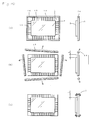
Fig. 10 shows exemplary processes.Fig. 10(a) shows a front view and a right side view of an LCD in a manufacture process. The LCD is composed of aTFT substrate 1 and aCF substrate 2. Although not illustrated, thin film transistors (TFTs) are arranged on theTFT substrate 1. Although not illustrated, a color filter (CF) is arranged on theCF substrate 2. TheCF substrate 2 is spaced at a very small gap away from theTFT substrate 1, and is laminated onto theTFT substrate 1 by a sealing member (not shown) that is arranged on the periphery of theCF substrate 2.Gate wiring lines 11, source wiring lines 12 and a short-circuit ring portion 13 are arranged in the outer rim portion of the surface of theTFT substrate 1. The short-circuit ring portion 13 short-circuits thegate wiring lines 11 and the source wiring lines 12 to prevent that the TFTs fail due to static electricity discharge, or the like. The short-circuit ring portion 13 is cut out and removed by the scribing and breaking method before the final inspection of the LCD (Fig. 10(b) ). After that, the edges of the thus-dividedTFT substrate 1 are chamfered by grindstones 7 (Fig. 10(c) ). - However, in recent years, there is a trend to increase the display screen size of LCD and reduce the outer periphery portion of the display screen. Correspondingly, an outer peripheral part L of the
TFT substrate 1 becomes narrower that protrudes from theCF substrate 2. As the outer peripheral part L of theTFT substrate 1 becomes narrower, it is hard to provide enough space to grind the cut end surfaces of theTFT substrate 1 by using thegrindstones 7. - Also, in the process in that glass substrates are chamfered by grinding members, since grinding members produce very small glass powder when grinding and removing the glass substrates, the very small glass powder may cause worksite environment deterioration. In addition, in order to remove very small glass powder that adheres on the glass substrate, it is necessary to clean the glass substrate after the chamfering process.
-
- [Patent Document 1] Japanese Patent Laid-Open Publication No.
H08-6069 - The present invention is aimed at solving the problem in the conventional art. It is an object of the present invention it to provide a chamfering method that can be conducted even in small worksite space without using grinding members and without requiring a cleaning process after a chamfering process.
- A brittle material substrate chamfering method according to the present invention includes steps of drawing a scribe line, and heating and/or cooling a part in proximity to the scribe line. The scribe line is drawn on: a part of a surface of a brittle material substrate that extends along the edge of the brittle material substrate and has a width not more than 50% of the thickness of the brittle material substrate starting from the edge of the brittle material substrate whereby forming a crack inclined from the surface of the substrate toward a side end surface of the substrate. A part in proximity to the scribe line is heated and/or cooled so that a corner part of the edge of said brittle material substrate is cut out whereby chamfering said brittle material substrate.
- In this method, in order to more surely form the inclined crack, the scribe line can be drawn on said part of a surface of a brittle material substrate by a cutter wheel that includes two outer peripheral portions having a common rotation axis. The two outer peripheral portions have cone shapes or truncated cone shapes. The bottom surfaces of the cone shapes or truncated cone shapes are integrally formed so that a circumferential edge line as a cutting edge is formed. In addition, a plurality of inclined grooves can be formed along said circumferential edge line and inclined from said circumferential edge line toward one of the outer peripheral portions. It is preferable that said plurality of inclined grooves have the same shape on said circumferential edge line. In addition, the scribing movement direction of said cutter wheel can be specified so that one side of each of said inclined grooves with larger width and depth is located on the edge side of said brittle material substrate.
- Also, in this method, in order to more surely form the inclined crack, the scribe line can be drawn on said part of a surface of a brittle material substrate by a cutter wheel that includes two outer peripheral portions having a common rotation axis. The two outer peripheral portions have cone shapes or truncated cone shapes, and the bottom surfaces of the cone shapes or truncated cone shapes are integrally formed so that a circumferential edge line as a cutting edge is formed. The two outer peripheral portions have different angles from each other relative to said circumferential edge line.
- Each of the outer peripheral portions of said cutter wheel can be formed so as to have two angles by grinding.
- The scribe line drawn on said part of a surface of a brittle material substrate can be at least one of straight line, closed curve and unclosed curve.
- In the case where said brittle material substrate is a flat display panel glass substrate that has a short-circuit ring portion formed along the edges of this glass substrate, it is preferable that said short-circuit ring portion be cut out together with the corner part by the aforementioned method.
- According to a chamfering method of the present invention, since a brittle material substrate can be chamfered without using grinding members, conventional cleaning processes are not required after the chamfering process. Also, since grinding members are not used, a brittle material substrate can be chamfered even in small worksite space.
-
- [
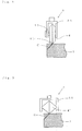
Fig. 1 ] Process chart showing an exemplary chamfering method according to the present invention. - [
Fig. 2 ] Schematic view showing a scribing process. - [
Fig. 3 ] Schematic view showing a scribing process using another cutter wheel. - [
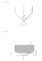
Fig. 4 ] Enlarged view illustrating the cutting edge of the cutter wheel. - [
Fig. 5 ] Enlarged view showing the cutting edge of a cutter wheel with inclined grooves. - [
Fig. 6 ] Enlarged view showing the cutting edge of a cutter wheel that has two outer peripheral portions with different angles from each other relative to the circumferential edge line of the cutter wheel. - [
Fig. 7 ] Process chart showing another exemplary chamfering method according to the present invention. - [
Fig. 8 ] Schematic view showing a chamfering processing according to an example 1. - [
Fig. 9 ] Schematic view showing a chamfering processing according to a comparative example 1. - [
Fig. 10 ] Process chart showing conventional LCD manufacturing processes. -
- 1
- TFT Substrate (Brittle Material Substrate)
- 2
- CF Substrate (Brittle Material Substrate)
- 4
- Cutter Wheel
- C
- Crack
- a
- Substrate Thickness
- b1, b2
- Distance from Substrate Edge
- 11
- Glass Substrate
- 42
- Inclined Groove
- The following description will describe a chamfering method according to the present invention with reference to drawings. However, the present invention is not limited to their embodiment.
-
Fig. 1 is a process chart showing a chamfering method according an embodiment of the present invention. An LCD shown inFig. 1 is composed of aTFT substrate 1 and aCF substrate 2. TheCF substrate 2 is spaced at a very small gap away from theTFT substrate 1, and is laminated onto theTFT substrate 1. The outer peripheral part of theTFT substrate 1 is chamfered as shown in the process chart ofFig. 1 . First, scribe lines are drawn by a cutter wheel on a predetermined part of a surface of theTFT substrate 1 of a brittle material substrate that extends along the edge of theTFT substrate 1 and has a predetermined width starting from the edge of the TFT substrate 1 (Fig. 1(a) ). It is important to draw the scribe line by using thecutter wheel 4 at a position in an area of the surface of theTFT substrate 1 that has a width not more than 50% of the thickness of theTFT substrate 1 starting from the edge ofTFT substrate 1. Thus, crack lines C are formed inclined from the surface toward the side end surfaces of theTFT substrate 1. In the case where the scribe line is drawn at a position in an area of the surface of theTFT substrate 1 that has a width more than 50% of the thickness of theTFT substrate 1 starting from the edge ofTFT substrate 1, the crack C cannot be formed so as to be inclined toward the side end surface of theTFT substrate 1 but is formed extending in substantially the vertical direction in the scribing process. In this case, theTFT substrate 1 cannot be chamfered. It is preferable that the scribe line be drawn at a position in an area of the surface of theTFT substrate 1 that has a width of 10% to 50% of the thickness of theTFT substrate 1 starting from the edge ofTFT substrate 1. - The scribing process is now described using the
cutter wheel 4.Fig. 2 is a schematic view showing acutter head 5 with thecutter wheel 4 attached thereto. Thecutter wheel 4 is attached to a supporting frame member of thecutter head 5 to be rotatably supported by a shaft 51. Thecutter wheel 4 has two truncated cone shapes having a common rotation axis. The bottom surfaces of the truncated cone shapes are integrally formed so that a circumferential edge line as a cutting edge is formed. Thecutter head 5 is mounted to a scribing device. Thecutter wheel 4 rotates and moves on the surface of thesubstrate 1 in press contact with theTFT substrate 1. Thus, a scribe line SL is formed on thesubstrate 1 so that an inclined crack C is formed. A load applied to thecutter wheel 4 and scribing speed of thecutter wheel 4 can be suitably determined in accordance with the type, the thickness and the like of thesubstrate 1. Typically, a load applied to thecutter wheel 4 can be 0.05 to 0.4 MPa, and scribing speed of thecutter wheel 4 can be 10 to 500 mm/sec. - In addition to the
cutter wheel 4, known cutter wheels can be used and attached to thecutter head 5 shown inFig. 2 . For example, an example of known cutter wheels can be provided by a cutter wheel 4' shown inFig. 3 that has two cone shapes having a common rotation axis. The bottom surfaces of the cone shapes of the cutter wheel 4' are integrally formed so that a circumferential edge line as a cutting edge is formed. The cutter wheel preferably has an outer diameter in arange 1 to 10 mm. If the cutter wheel has an outer diameter smaller than 1 mm, the handleability and the durability of the cutter wheel will decrease. If the cutter wheel has an outer diameter larger than 10 mm, the inclined crack may not be deeply formed in the scribing process. The cutter wheel more preferably has an outer diameter in arange 1 to 5 mm. - The cutting edge of the cutter wheel can be formed as follows. For example, as shown in
Fig. 4 , the cutting edge of the cutter wheel is first roughly grinded at an edge angle of Θ1. In the cutter wheel with the edge angle of Θ1 is required, the cutting edge of the cutter wheel is finely grinded, and is then provided with later-discussed inclined grooves that are formed along the cutting edge if necessary. On the other hand, in the case where the cutter wheel of an edge angle of Θ2 is required, the roughly-grinded cutter wheel with the edge angle of Θ1 is finely grinded so that the edge angle with the edge angle of Θ2 is formed (dashed lines inFig. 4 ). After that, the later-discussed inclined grooves are formed similar to the aforementioned inclined groove formation if necessary. In the case where the cutter wheel is aimed at being used after the cutting edge with two edge angles is formed by two grinding stages, If a plurality of the cutter wheels are stocked that have previously grinded at the edge angle of Θ1, the cutter wheels with different edge angles can be provided within a short time only by finely grinding their cutting edges. Therefore, it is possible to shorten delivery times, and additionally to produce small batches of a variety of products. The aforementioned two-grinding-stage method can be applied to the cutter wheel shown inFigs 3 and the later-discussed cutting wheel shown inFig. 6 . - In order to form the crack C, which is inclined relative to the substrate surface, it is preferable that inclined grooves 42 be formed along the cutting edge of a wheel main body 41 at a predetermined inclination angle relative to the axial direction of the
cutter wheel 4. The interval between the inclined grooves 42 preferably falls within a range of 20 to 200 µm. As for the depths at the both ends of the inclined groove 42, it is preferable that a depth d1 fall within a range of 2 to 2500 µm, and a depth d2 fall within a range of 1 to 20 µm. The inclined groove 42 can have various shapes such as U shape, V shape, saw-teeth shape, and rectangular recessed shape as viewed from the lateral side. When a scribe line is drawn by using thiscutter wheel 4, the crack C is formed inclined downward toward the left side in the Figure. - In the case where the cutter wheel shown in
Fig. 6 is alternatively used that has two outer peripheral portions with different edge angles relative to the edge line of the cutting edge, the crack C can be formed inclined relative to the substrate surface. When a scribe line is drawn by using a cutter wheel 43 shown inFig. 6 , the crack C is formed inclined downward toward the left side in the Figure similar to the cutter wheel shown inFig. 5 . The inclination of the crack C is generally proportional to the difference of the left and right edge angles relative to the edge line of the cutting edge. The inclination of the crack C will increase with the difference of the left and right edge angles. - Even in the case where a cutter wheel is used that has the same left and right edge angles relative to the edge line of the cutting edge, when a scribe line is drawn with the edge line of the cutter wheel being inclined relative to the substrate, the crack can be formed inclined relative to the substrate surface.
- Subsequently, as shown in
Fig. 1(b) , according to the chamfering method of the present invention, the scribe line SL and a part in proximity to the scribe line SL are heated and/or cooled. Expansion or contraction difference is produced in the thickness direction of theTFT substrate 1 by heating and/or cooling theTFT substrate 1. Accordingly, the crack C will extend and reach the side end surface of thesubstrate 1. As a result, a corner part of the edge of theTFT substrate 1 can be cut out. In addition, in order that the crack C can surely extend and, reach the side end surface of the substrate, it is preferable that the substrate be heated and then cooled. - A known means can be used for heating and cooling the substrate. For example, examples of the heating means can be provided by laser heating, steam heating, infrared radiation heating by halogen heater, and the like. For example, examples of the cooling means can be provided by discharge of gas and liquid cooling mediums such as carbon dioxide, nitrogen, helium, water, and the like.
- As shown in
Fig. 1(c) , the corner part of the edge is cut out from theTFT substrate 1, and is retrieved as cullet 61 by suction. The corner part of the edge of theTFT substrate 1 is thus cut out in the previous heating and/or cooling process, and is removed from the TFT substrate by its own weight. If the corner part of the edge is insufficiently removed, an external force may be applied to the corner part of the edge to sufficiently remove the corner part of the edge. - Although the chamfering method according to the present invention has been illustratively described to be applied to a method for chamfering a TFT substrate of LCD, the chamfering method according to the present invention can be applied to methods for chamfering brittle material substrates such as glass substrate of FPDs (e.g., PDPs). In addition to the glass substrate, examples of the brittle material substrates to be chamfered by the chamfering method of the present invention can be provided by various types of substrates such as ceramic, silicon and sapphire substrates.
- In addition, the chamfering method according to the present invention can be applied to a product that has an edge line of closed curve.
Fig. 7 shows exemplary processes. As shown inFig. 7(a) , a patterning scribe line is drawn along the pattern of aproduct 6 that will have an edge line of closed curve on aglass substrate 7. Subsequently, a chamfering scribe line is drawn by using thecutter wheel 4. After that, a crack Co extends from the patterning scribe line along the pattern of theproduct 6. Thus, theproduct 6 can be lifted out from theglass substrate 7. Subsequently, as shown inFig. 7(b) , the edge of theproduct 6 is heated and/or cooled so that the corner part of the edge is cut out along a crack C. After that, the corner part is retrieved as cullet 61 by suction. Alternatively, the chamfering scribe line can be drawn in theproduct 6 after theproduct 6 is lifted out from theglass substrate 7. After that, the edge can be heated and/or cooled so that the corner part of the edge is cut out. - The following description will describe a chamfering method according to an example of the present invention. However, the present invention is not limited to the example.
- As shown in
Fig. 8 , a scribe line was drawn by using a cutter wheel shown in specifications of Table 1 at a position spaced away from an edge of aglass substrate 11 with thickness a of 0.7 mm at a distance b1 of 0.3 mm (43% of the thickness of the glass substrate) along the edge. The scribing conditions were cutting edge load of 0.14 MPa, and scribing speed of 300 mm/sec. Steam with temperature of about 100°C was discharged toward the scribe line for five seconds so that the scribe line was heated whereby chamfering theglass substrate 11. As a result, as shown inFig. 8 , the corner part of the edge of theglass substrate 11 was diagonally cut out so that theglass substrate 11 was chamfered. -
[Table 1] Specifications of Cutter Wheel Outer Diameter (mm) 2.0 Thickness (mm) 0.65 Material Cemented Carbide Cutting Edge Angle (°) 115 Groove Depth d1 (µm) 11 Groove Depth d2 (µm) 7 Groove Interval (µm) 47 - As shown in
Fig. 9 , a scribe line was drawn and was then heated similarly to the example 1 except that a scribing position was spaced away from an edge of aglass substrate 11 at a distance b2 of 0.5 mm (71% of the thickness of the glass substrate). As a result, as shown inFig. 9 , the corner part of the edge of theglass substrate 11 was substantially vertically cut out. - A scribe line was drawn and was then heated similarly to the example 1 except that a scribing position was spaced away from an edge of a glass substrate at a distance of 0.7 mm (100% of the thickness of the glass substrate). As a result, the corner part of the edge of the glass substrate was vertically cut out similar to the comparative example 1.
- According to a chamfering method of the present invention, since a brittle material substrate can be chamfered without using grinding members, the chamfering method of the present invention is useful.
Claims (8)
- A brittle material substrate chamfering method comprising the steps of:drawing a scribe line on a part of a surface of a brittle material substrate that extends along the edge of the brittle material substrate and has a width not more than 50% of the thickness of the brittle material substrate starting from the edge of the brittle material substrate whereby forming a crack inclined from the surface of the substrate toward a side end surface of the substrate; andheating and/or cooling a part in proximity to the scribe line so that a corner part of the edge of said brittle material substrate is cut out whereby chamfering said brittle material substrate.
- The chamfering method according to Claim 1, wherein the scribe line is drawn on said part of a surface of a brittle material substrate by a cutter wheel that includes two outer peripheral portions having a common rotation axis, wherein the two outer peripheral portions have cone shapes or truncated cone shapes, and the bottom surfaces of the cone shapes or truncated cone shapes are integrally formed so that a circumferential edge line as a cutting edge is formed, wherein a plurality of inclined grooves are formed along said circumferential edge line and inclined from said circumferential edge line toward one of the outer peripheral portions.
- The chamfering method according to Claim 2, wherein said plurality of inclined grooves have the same shape on said circumferential edge line.
- The chamfering method according to Claim 2 or 3, wherein the scribing movement direction of said cutter wheel is specified so that one side of each of said inclined grooves with larger width and depth is located on the edge side of said brittle material substrate.
- The chamfering method according to Claim 1, wherein the scribe line is drawn on said part of a surface of a brittle material substrate by a cutter wheel that includes two outer peripheral portions having a common rotation axis, wherein the two outer peripheral portions have cone shapes or truncated cone shapes, and the bottom surfaces of the cone shapes or truncated cone shapes are integrally formed so that a circumferential edge line as a cutting edge is formed, wherein the two outer peripheral portions have different angles from each other relative to said circumferential edge line.
- The chamfering method according to any of Claims 2 to 5, wherein each of the outer peripheral portions of said cutter wheel is formed so as to have two angles by grinding.
- The chamfering method according to any of Claims 1 to 6, wherein the scribe line drawn on said part of a surface of a brittle material substrate is at least one of straight line, closed curve and unclosed curve.
- The chamfering method according to any of Claims 1 to 7, wherein said brittle material substrate is a flat display panel glass substrate that has a short-circuit ring portion formed along the edges of this glass, substrate, wherein said short-circuit ring portion is cut out simultaneously when the corner part of the edge of the brittle material substrate is cut out.
Applications Claiming Priority (2)
| Application Number | Priority Date | Filing Date | Title |
|---|---|---|---|
| JP2008142394 | 2008-05-30 | ||
| PCT/JP2009/058253 WO2009145026A1 (en) | 2008-05-30 | 2009-04-27 | Method for chamfering brittle material substrate |
Publications (1)
| Publication Number | Publication Date |
|---|---|
| EP2286972A1 true EP2286972A1 (en) | 2011-02-23 |
Family
ID=41376912
Family Applications (1)
| Application Number | Title | Priority Date | Filing Date |
|---|---|---|---|
| EP20090754534 Withdrawn EP2286972A1 (en) | 2008-05-30 | 2009-04-27 | Method for chamfering brittle material substrate |
Country Status (7)
| Country | Link |
|---|---|
| US (1) | US20110107894A1 (en) |
| EP (1) | EP2286972A1 (en) |
| JP (1) | JP5356376B2 (en) |
| KR (1) | KR101228959B1 (en) |
| CN (1) | CN102046346B (en) |
| TW (1) | TWI440528B (en) |
| WO (1) | WO2009145026A1 (en) |
Cited By (2)
| Publication number | Priority date | Publication date | Assignee | Title |
|---|---|---|---|---|
| WO2014012125A1 (en) * | 2012-07-17 | 2014-01-23 | Lisec Austria Gmbh | Method and arrangement for creating bevels on the edges of flat glass |
| RU2588514C1 (en) * | 2012-07-17 | 2016-06-27 | Лисец Аустриа Гмбх | Method and apparatus for creating skews on edges of flat glass |
Families Citing this family (22)
| Publication number | Priority date | Publication date | Assignee | Title |
|---|---|---|---|---|
| KR101345587B1 (en) * | 2012-01-09 | 2013-12-27 | 주식회사 라미넥스 | Method for cutting of corner of glass |
| US9028296B2 (en) * | 2012-08-30 | 2015-05-12 | Corning Incorporated | Glass sheets and methods of shaping glass sheets |
| KR101355807B1 (en) | 2012-09-11 | 2014-02-03 | 로체 시스템즈(주) | Curve cutting method for non-metallic materials |
| JP6428642B2 (en) * | 2013-12-27 | 2018-11-28 | Agc株式会社 | Method for processing brittle plate and apparatus for processing brittle plate |
| EP2978716A1 (en) | 2014-02-10 | 2016-02-03 | LISEC Austria GmbH | Method for cutting laminated glass |
| KR102204535B1 (en) * | 2014-05-19 | 2021-01-19 | 동우 화인켐 주식회사 | Apparatus for processing edge of glass substrate and method for processing edge of glass substrate using the same |
| KR20160001896U (en) * | 2014-11-25 | 2016-06-02 | 동우 화인켐 주식회사 | Apparatus for cutting edges of glass substrate |
| KR20160001895U (en) * | 2014-11-25 | 2016-06-02 | 동우 화인켐 주식회사 | Apparatus for cutting edges of glass substrate |
| KR20160001894U (en) * | 2014-11-25 | 2016-06-02 | 동우 화인켐 주식회사 | Apparatus for cutting corner of glass substrate |
| KR20160001891U (en) * | 2014-11-25 | 2016-06-02 | 동우 화인켐 주식회사 | Apparatus for cutting edge of glass substrate |
| KR102307261B1 (en) | 2015-05-27 | 2021-10-01 | 삼성디스플레이 주식회사 | Display device |
| JP6544149B2 (en) * | 2015-08-31 | 2019-07-17 | 三星ダイヤモンド工業株式会社 | Method of forming inclined cracks in brittle material substrate and method of dividing brittle material substrate |
| KR102607582B1 (en) * | 2016-08-30 | 2023-11-30 | 삼성디스플레이 주식회사 | Cover window, display device including a cover window, and method of manufacturing a cover window |
| JP7257675B2 (en) * | 2019-07-29 | 2023-04-14 | 三星ダイヤモンド工業株式会社 | Method for dividing brittle material substrate |
| WO2021162109A1 (en) * | 2020-02-14 | 2021-08-19 | 日昌株式会社 | Glass and glass processing method |
| KR102462339B1 (en) * | 2020-07-22 | 2022-11-04 | (주)하나기술 | Ultra-thin glass with enhanced impact resistance and method for manufacturing thereof |
| KR20220087220A (en) * | 2020-12-17 | 2022-06-24 | 코닝 인코포레이티드 | Heat chamfering method and apparatus for a glass substrate |
| JP7782191B2 (en) * | 2021-03-31 | 2025-12-09 | 大日本印刷株式会社 | Glass substrate, glass laminate, display device and electronic device |
| KR102860427B1 (en) * | 2021-04-01 | 2025-09-16 | 코닝 인코포레이티드 | Heat chamfering device and method |
| CN113427340A (en) * | 2021-05-20 | 2021-09-24 | 基迈克材料科技(苏州)有限公司 | Chamfering device and chamfering method thereof |
| CN113399846A (en) * | 2021-06-01 | 2021-09-17 | 武汉先河激光技术有限公司 | Laser chamfering method and device for hard and brittle material |
| CN116277549A (en) * | 2023-04-23 | 2023-06-23 | 天津市环智新能源技术有限公司 | Silicon rod processing method, silicon rod, silicon wafer and solar cell |
Family Cites Families (20)
| Publication number | Priority date | Publication date | Assignee | Title |
|---|---|---|---|---|
| US2207433A (en) * | 1938-03-14 | 1940-07-09 | Harry H Straus | Means for sharpening a circular knife |
| FR2466441A1 (en) * | 1979-10-03 | 1981-04-10 | Saint Gobain | Cutting of glass panes by scoring, then bending to cause fracture - using asymmetric scoring wheel so smooth cut edges are obtd. which do not need grinding |
| JP2785906B2 (en) * | 1994-02-14 | 1998-08-13 | 日本板硝子株式会社 | Glass plate cutting method |
| JP3241208B2 (en) | 1994-06-20 | 2001-12-25 | 三菱電機株式会社 | Active matrix substrate, liquid crystal display device using the same, and method of manufacturing the same |
| JPH09225665A (en) * | 1996-02-22 | 1997-09-02 | Seiko Epson Corp | Glass substrate chamfering method, glass substrate for liquid crystal panel and liquid crystal panel using the method |
| JPH09278474A (en) * | 1996-04-08 | 1997-10-28 | Nippon Sheet Glass Co Ltd | Glass wheel cutter and glass plate cutting method |
| JPH11179694A (en) * | 1997-12-17 | 1999-07-06 | Sharp Corp | Substrate cutting method and cutting device |
| JP2989602B1 (en) * | 1999-01-28 | 1999-12-13 | 三星ダイヤモンド工業株式会社 | Glass cutter wheel |
| JP3370314B2 (en) * | 2000-08-04 | 2003-01-27 | 三星ダイヤモンド工業株式会社 | Cutter wheel for brittle substrates |
| EP1179512B1 (en) * | 2000-08-11 | 2011-12-28 | Mitsuboshi Diamond Industrial Co., Ltd. | Cutter wheel, apparatus and method for scribing brittle materials |
| CN1970266B (en) * | 2001-03-16 | 2010-09-01 | 三星宝石工业株式会社 | Cutter wheel, scribing equipment using the same and equipment for manufacturing the same |
| ATE402125T1 (en) * | 2001-12-18 | 2008-08-15 | Mitsuboshi Diamond Ind Co Ltd | TIP HOLDER AND PRODUCTION PROCESS THEREOF AS WELL AS SCRATCHING DEVICE AND HAND CUTTER WITH THE TIP HOLDER |
| ATE458597T1 (en) * | 2002-04-01 | 2010-03-15 | Mitsuboshi Diamond Ind Co Ltd | SUB-METHOD FOR FRAGILE MATERIAL SUBSTRATE AND SUB-DEVICE USING THE PROCESS |
| US20040123717A1 (en) * | 2002-04-02 | 2004-07-01 | Kazuya Maekawa | Cutter wheel, device and method using the cutter wheel, method of dividing laminated substrate, and method and device for manufacturing cutter wheel |
| TW200408061A (en) * | 2002-07-02 | 2004-05-16 | Mitsuboshi Diamond Ind Co Ltd | Substrate slicing system for sealed substrates and the substrate slicing method |
| TWI286232B (en) * | 2002-10-29 | 2007-09-01 | Mitsuboshi Diamond Ind Co Ltd | Method and device for scribing fragile material substrate |
| WO2004048058A1 (en) * | 2002-11-22 | 2004-06-10 | Mitsuboshi Diamond Industrial Co.,Ltd. | Method for dividing substrate and method for manufacturing substrate using such method |
| CN1914014B (en) * | 2004-02-02 | 2011-04-06 | 三星钻石工业股份有限公司 | Cutter wheel, scribing method and dividing method for brittle material substrate using same, and method for manufacturing cutter wheel |
| JP3981374B2 (en) * | 2004-09-29 | 2007-09-26 | Hoya株式会社 | Manufacturing method of glass substrate for magnetic disk and manufacturing method of magnetic disk |
| JP4406752B2 (en) * | 2005-05-27 | 2010-02-03 | 日本電気硝子株式会社 | Glass substrate end face processing apparatus and end face processing method |
-
2009
- 2009-04-27 CN CN200980119942.9A patent/CN102046346B/en not_active Expired - Fee Related
- 2009-04-27 WO PCT/JP2009/058253 patent/WO2009145026A1/en not_active Ceased
- 2009-04-27 KR KR1020107027715A patent/KR101228959B1/en not_active Expired - Fee Related
- 2009-04-27 EP EP20090754534 patent/EP2286972A1/en not_active Withdrawn
- 2009-04-27 JP JP2010514422A patent/JP5356376B2/en not_active Expired - Fee Related
- 2009-04-27 US US12/995,011 patent/US20110107894A1/en not_active Abandoned
- 2009-04-29 TW TW98114146A patent/TWI440528B/en not_active IP Right Cessation
Non-Patent Citations (1)
| Title |
|---|
| See references of WO2009145026A1 * |
Cited By (4)
| Publication number | Priority date | Publication date | Assignee | Title |
|---|---|---|---|---|
| WO2014012125A1 (en) * | 2012-07-17 | 2014-01-23 | Lisec Austria Gmbh | Method and arrangement for creating bevels on the edges of flat glass |
| CN104364209A (en) * | 2012-07-17 | 2015-02-18 | 李赛克奥地利有限公司 | Method and arrangement for creating bevels on the edges of flat glass |
| EP2734480B1 (en) | 2012-07-17 | 2016-03-09 | LISEC Austria GmbH | Method and apparatus for chamfering a glassplate |
| RU2588514C1 (en) * | 2012-07-17 | 2016-06-27 | Лисец Аустриа Гмбх | Method and apparatus for creating skews on edges of flat glass |
Also Published As
| Publication number | Publication date |
|---|---|
| KR20110016927A (en) | 2011-02-18 |
| TW201002476A (en) | 2010-01-16 |
| WO2009145026A1 (en) | 2009-12-03 |
| JPWO2009145026A1 (en) | 2011-10-06 |
| KR101228959B1 (en) | 2013-02-01 |
| CN102046346B (en) | 2014-04-09 |
| JP5356376B2 (en) | 2013-12-04 |
| US20110107894A1 (en) | 2011-05-12 |
| CN102046346A (en) | 2011-05-04 |
| TWI440528B (en) | 2014-06-11 |
Similar Documents
| Publication | Publication Date | Title |
|---|---|---|
| US20110107894A1 (en) | Brittle Material Substrate Chamfering Method | |
| KR101164856B1 (en) | Method for manufacturing brittle material scribing wheel | |
| JP5185412B2 (en) | Method of scribing and dividing brittle material substrate using cutter wheel | |
| KR101755062B1 (en) | Glass substrate and method for manufacturing glass substrate | |
| JP5506747B2 (en) | Cutter wheel and manual scribing tool, scribing device and scribing method | |
| KR101712668B1 (en) | Method and apparatus for chamfering hard brittle plate | |
| CN103958424B (en) | Glass plate processing device and glass plate processing method | |
| TWI385134B (en) | Crossing method of brittle material substrate | |
| EP1386891A1 (en) | Cutter wheel, device and method using the cutter wheel, method of dividing laminated substrate, and method and device for manufacturing cutter wheel | |
| JP2010234518A (en) | Glass substrate and method for manufacturing the same | |
| TW201338915A (en) | End surface polishing device of glass substrate, end surface polishing method of glass substrate, and manufacturing method of glass substrate | |
| TWI353633B (en) | ||
| JP5370913B2 (en) | Glass substrate end surface polishing apparatus and end surface polishing method thereof | |
| HK1146037A (en) | Scribing method and cutting method for fragile material substrate | |
| HK1099925B (en) | Cutter wheel, scribing method and cutting method for fragile material substrate using the cutter wheel, and method of manufacturing cutter wheel | |
| HK1155691A (en) | Cutter wheel, scribing method and cutting method for fragile material substrate using the cutter wheel, and method of manufacturing cutter wheel | |
| HK1155692A (en) | Cutter wheel, scribing method and cutting method for fragile material substrate using the cutter wheel, and method of manufacturing cutter wheel |
Legal Events
| Date | Code | Title | Description |
|---|---|---|---|
| PUAI | Public reference made under article 153(3) epc to a published international application that has entered the european phase |
Free format text: ORIGINAL CODE: 0009012 |
|
| 17P | Request for examination filed |
Effective date: 20101230 |
|
| AK | Designated contracting states |
Kind code of ref document: A1 Designated state(s): AT BE BG CH CY CZ DE DK EE ES FI FR GB GR HR HU IE IS IT LI LT LU LV MC MK MT NL NO PL PT RO SE SI SK TR |
|
| AX | Request for extension of the european patent |
Extension state: AL BA RS |
|
| DAX | Request for extension of the european patent (deleted) | ||
| STAA | Information on the status of an ep patent application or granted ep patent |
Free format text: STATUS: THE APPLICATION HAS BEEN WITHDRAWN |
|
| 18W | Application withdrawn |
Effective date: 20150108 |