EP2286689B1 - Zubehör-Tragegestellsystem für Schauspieler - Google Patents
Zubehör-Tragegestellsystem für Schauspieler Download PDFInfo
- Publication number
- EP2286689B1 EP2286689B1 EP20100173336 EP10173336A EP2286689B1 EP 2286689 B1 EP2286689 B1 EP 2286689B1 EP 20100173336 EP20100173336 EP 20100173336 EP 10173336 A EP10173336 A EP 10173336A EP 2286689 B1 EP2286689 B1 EP 2286689B1
- Authority
- EP
- European Patent Office
- Prior art keywords
- plate
- harness
- frame according
- backrest
- holes
- Prior art date
- Legal status (The legal status is an assumption and is not a legal conclusion. Google has not performed a legal analysis and makes no representation as to the accuracy of the status listed.)
- Active
Links
Images



Classifications
-
- A—HUMAN NECESSITIES
- A45—HAND OR TRAVELLING ARTICLES
- A45F—TRAVELLING OR CAMP EQUIPMENT: SACKS OR PACKS CARRIED ON THE BODY
- A45F3/00—Travelling or camp articles; Sacks or packs carried on the body
- A45F3/10—Pack-frames carried on the body
Definitions
- the present invention relates generally to the field of stage props, and more particularly to an accessory harness that allows a stage performer to wear at least one stage accessory on the back. It proposes more particularly a frame of such a harness, as well as a harness incorporating it.
- the invention finds applications, particularly in the field of live performance, namely including music hall, theater, dance, cabaret, circus, etc.
- a Cabaret magazine such as the current magazine “Féerie” of the Moulin Rouge Ball, is composed of a multitude of about 100 artists, including 60 “Doriss Girls” recruited around the world, using 1000 feather costumes, rhinestones and sequins.
- the entertainment effect provided to the spectators by the show comes mainly from the visual quality of the artists' movements, and their accessories, on the stage. In this respect, the amplitude, the speed of execution, and the synchronization of these movements are decisive.
- the frame of a harness is made with portions of rods or metal son, of circular section with a diameter of a few millimeters or so, and which are conventionally called "piano strings" .
- Such elements are carbonized steel (hardened), they therefore have a high tensile strength, along with a certain static forming capacity, and a certain elasticity in dynamics.
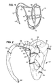
- a part 11 is made to lean against the back of the artist, and parts 12 and 13 for holding the harness on the shoulders of the artist, in the manner of suspenders. More particularly, properly shaped elements are welded together in places so that the frame as a whole affects a configuration giving the parts 11, 12 and 13 above, according to its function. Brazing points 14 are made in particular at the end of the shoulder straps 12 and 13, at the intersection between portions of piano wire that intersect, and / or at the point of contact between such portions that meet . Perforated washers 15 are also welded to the piano strings, at specific locations in the backrest portion 11, to allow attachment of the accessory with bolts (not shown) passing through these washers. The frame is then dressed, by covering with foam, cotton wool, carded cotton or the like, and finally a ceremonial fabric such as a silky fabric sewn over.
- the entire harness Because of the constitution of its frame, the entire harness has a certain overall elasticity, and especially parts 12 and 13 which form the straps. The harness is therefore subjected to deformation stresses, which are exerted almost at all points of the frame.
- the alignment of the accessory of the artist concerned may deviate from that of the accessories of the other artists on the stage, which results in a visual imperfection for the audience.
- the lack of positioning of the accessory generates an asymmetry of the forces exerted on the shoulders of the artist, which must be compensated by postures and / or compensatory movements with very negative effects. This results in effect muscle and / or joint pain for the artist, both during the effort and then.
- US504101 A discloses a device, according to the prior art, for hanging on the shoulders a backpack, a tourist bag and other such bag.
- the invention aims to eliminate, or at least mitigate, all or part of the disadvantages of the prior art mentioned above.
- a first aspect of the invention provides a reinforcement according to claim 1.
- the parts of the frame that are in contact with the body of the artist, through a dressing made for example of foam and ornamental fabric, are rigid. They can not be distorted by the swaying of the stage accessory that is caused by the movements of the artist. Nevertheless, a certain elasticity remains locally at the junction between the backsplash and the straps, which elasticity makes it possible in particular to dampen these swings to a certain extent.
- the harness is therefore stronger and more resistant in time, while being more comfortable and more respectful of the physical integrity of the artists. Maintenance operations are virtually eliminated, or at least much less frequently needed.
- the backsplash comprises a rigid front plate and a back plate, substantially vertical and parallel to each other while being held rigidly spaced apart from one another at least a part of their surfaces opposite. This makes it possible to increase the rigidity of the armature.
- Another aspect of the invention relates to a harness for a stage artist, comprising a frame according to the first aspect.
- a harness consists of a frame covered with a covering 30.
- the latter comprises a layer of foam, cotton wool, carded cotton or the like, itself covered by a decorative coating such as silky fabric, usually of a shimmering color.
- This composition of the dressing is an example only, any other composition may be preferred, according to the needs of the application. Also, more complex skins can be used, for example to cover different parts of the frame with different materials, different textures, colors, etc.
- the frame itself essentially comprises a rigid backsplash 21, coupled to two rigid branches forming straps 22 and 23 through, for each of them, an elastic connecting element.
- an elastic connecting element To the Figure 2 only the elastic joining element 24 associated with the left shoulder 22 is visible, the one associated with the right shoulder 23 being shown covered by the covering 30.
- the backsplash 21 and the straps 22 and 23 are said to be rigid in the sense that, under the normal conditions of use provided for the application in question, they offer no capacity for deformation, elastic or otherwise, by bending, twisting, or other. This does not mean that these constituent elements could not be deformed, even broken, if they were subjected to efforts exceeding a certain threshold, but this means that this threshold is well beyond the forces likely to be applied to them in conditions of normal use of the harness.
- the harness is represented in its normal configuration, when positioned and held on the shoulders of a user, for example a cabaret dancer.
- the backsplash 21 is plated on the back of the user, preferably in the upper part of the back so as not to hinder the movements of the basin and legs of the artist. Maintaining the backrest in the pressed position against the back of the dancer results from the action of the branches forming straps, such as the strap 22. Indeed, this strap is bent backwards so as to pass under the armpits of the dancer.
- Each ramp ends with a hook bearing the reference 42 for the ramp 22 visible at the Figure 2 and at the Figure 3 , and the reference 43 for the ramp 23 which is visible only to the Figure 2 .
- a thong or strap 35 can pass in the back of the dancer to connect the hooks 42 and 43 to one another, and / or backrest 21, to stabilize the position of the harness despite the movements of the dancer, without, however, hurting her or hindering her movements.
- the strap 35 may be made of an elastic material or not. This may be for example a leather belt, a cotton ribbon, an elastic band, or the like. These examples are in no way limiting.
- the backrest thus comprises three studs 31, 32 and 33.
- the stud 31 is disposed in the upper part of the backrest, on the left, while the stud 32 is disposed in the upper part, on the right, and that the stud 33 is disposed in the lower part, substantially in the center (considered along a horizontal axis from the left to the right of the dancer).
- This number and this arrangement of the studs allow fixation in good conditions of stability, at least one accessory on the backsplash.
- the accessory may comprise a plate of dimensions in relation to those of the backsplash, provided with holes corresponding to the studs 31, 32 and 33, which enable the platen to be pressed and fixed against the backrest of the harness, for example using bolts of type "butterfly".
- the studs 31, 32 and 33 may be pressed and fixed against the backrest of the harness, for example using bolts of type "butterfly".
- any variation in the number or position of the studs is possible, depending on the intended application, and in particular the number, dimensions and weight of the accessories to support.
- more than one accessory can be maintained on the backrest 21 by means of such studs.
- each of the straps 22 and 23 may be in the form of a tube, for example an aluminum tube 6060 T6, of circular section with a diameter equal to 20 millimeters.
- the tube is suitably bent by force, and flattened at its ends.
- the bending of each of the tubes can be performed using a suitable template.
- the upper end of the tube intended to be coupled to the backsplash 21 via an elastic element such as the element 24, is crushed to affect a substantially horizontal flat shape.
- the free end of the ramp to which is fixed the hook 42 or 43, is crushed so as to have a substantially vertical flat shape.
- the upper end of the strap can lie flat on the shoulder of the dancer, and its lower end can rest flat against its side.
- the hook 42 may ideally be fixed on the outer side of the lower end of the left shoulder strap 22, so as not to hurt the dancer.
- the hook 43 of the right shoulder strap 23 (visible on the Figure 2 ) is preferably located on the outer face of this ramp, for the same reasons.
- Fixing hooks 42 and 43 may be made by screws or rivets, preferably ensuring that no part exceeds the inner face of the flat portion of the free end of the ramp. For example, if a screw is used, it is oriented from the inside to the outside and its head is held by a countersunk hole.
- the attachment is obtained by a rivet, the end of which is located on the inside, that is to say on the flank side of the dancer, is matted or filed down.
- no protruding part of the fastening means of the hook is then likely to hurt the artist when the harness is clamped in position, with the free ends of the straps pressed against its flanks.
- the harness is used in conditions of comfort and ergonomics optimized.
- the backrest 21 essentially comprises three rigid parts, made integral with each other non-elastically.
- the fixing means of these three elements 25, 26 and 27 do not introduce any point of deformation of the backrest, play, or elasticity, under the normal conditions of use of the harness.
- these three elements are rigid and rigidly interdependent on each other. In fact, thus providing three elements instead of, for example, a single plate, precisely increases the rigidity of the backrest as a whole.
- the backsplash comprises a rear plate 25 and a front plate 26.
- these two plates rest against each other in the lower part of the backsplash, while they are spaced apart from each other. other in the upper part.
- a bracket 27 is in fact disposed between the two plates 25 and 26, serving as a spacer between these two plates and participating in the best rigidity of the assembly.
- the two plates 25 and 26 and the bracket 27 may for example be made of aluminum plated sheet, for example, in the material known under the name AU4GA5 (2024). It is a sheet with a 5 micron aluminum plating, which has the advantage of being a clean material. 4G aluminum is a hard-cured material, so that it is particularly resistant even at low thickness. For example, plates 12 millimeters thick are used, which gives the armature a very reasonable weight, and even less than for reinforcements steel of the prior art described in the introduction. This further allows bending of the sheet, as will now be described for each of the plates 25 and 26, and the square 27.
- FIG. 5 there is shown a plan view of the front plate 26.
- This plate affects the general shape of a heart, with the tip downwards and two left and right ears extending upwards.
- the upper edge 51 of the plate 26, between these ears affects a concave shape with a certain curvature which will be discussed later.
- drilled holes 52 for example of diameter equal to 4 millimeters.
- the plate 26 is preferably symmetrical with respect to this vertical axis 53.
- a light 54 for example of diameter equal to 120 millimeters, is open in the center of the plate, in order to reduce the weight of the reinforcement and the surface area. pressing against the back of the artist. This light is obtained by piercing the plate 26 with a circular hole whose center corresponds to the intersection between the vertical axis 53 and a horizontal axis 55.
- Holes 56 and 57 are drilled in the area corresponding to the base of the upper right and left ears of the plate. The respective centers of these holes are aligned on the same horizontal line. According to the vertical, this line is substantially between the lowest point of the curvature of the upper edge 51, and the highest point of the light 54.
- the holes 56 and 57 have for example a diameter equal to 15 millimeters.
- hole 58 is also drilled along the vertical axis of symmetry 53, substantially at equal distance (along this vertical axis) from the horizontal axis 55 as the holes 56 and 57, so between the most bottom of the light 54 and the lower end of the plate 26. Its diameter is for example equal to 6 millimeters.
- Another hole 59 is further pierced between the hole 58 and the lower end of the plate 26. It is an oblong hole whose greatest length (which extends vertically) is equal to about 10 millimeters, and the width (horizontally) is equal to about 8 millimeters, in one example. This hole can be used for the passage of a holding tape such as the ribbon 35 visible in the Figure 3 .
- the front plate 26 is slightly bent forwardly from an axis corresponding substantially to the horizontal axis 55 of the Figure 5 .
- This bending is intended to allow the plate 26 to marry the rounded shape of the back, at the base of the neck, the artist.
- the bending is typically limited to a maximum angle of about 30 ° with the vertical.
- the lower end of the plate is, conversely, slightly curved rearward, from a horizontal axis passing substantially through the center of the hole 59. This bending is intended to prevent the end plate 26 does not hurt the artist by rubbing against his spine.
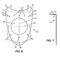
- the back plate 25 will now be described with reference to the diagrams of Figures 6 and 7 .
- this plate is represented flat.
- To the Figure 7 it is shown in a view on the left side, after two folds in its upper part, which will be explained below.
- the plate 25 also affects the general shape of a heart whose dimensions and shape correspond globally to that of the plate 26 of the Figure 5 , and are even identical for the lower part.
- the plate 25 also has a concave shape facing upwards at its upper edge 61. It also comprises a circular opening 64, of the same radius as the opening 54 of the plate 26, and whose center corresponds to the intersection of a vertical symmetric axis 63 and a horizontal axis 65.
- the plate 25 comprises holes 68 and 69 respectively corresponding to the holes 58 and 59 of the plate 26 of the Figure 5 regarding the position and the passage dimensions.
- the plate 25 comprises two holes 66 and 67, positioned as the holes 56 and 57 of the plate 26 so as to be concentric when the plates are superimposed, but with a smaller diameter, namely for example, a diameter of 6 millimeters as the hole 68.
- the holes 66, 67 and 68 are intended for fixing long screws including the threaded rods protruding towards the rear correspond to the studs 32, 31 and 33 respectively ( Figure 2 ).
- the holes 56 and 57 in the front plate 26 are intended to allow the insertion of these screws or bolts and / or their tightening by screwdriver or key, once the two plates 25 and 26 and the spacer 27 assembled.
- holes 73 are evenly distributed along the left and right edges of the plate 25 between the level of the horizontal axis 65 and the bottom of the plate 25, for example three holes on the left side and three holes on the right side of the plate.
- Other holes 74 for example five in number, are drilled along a horizontal line which is, in the vertical direction, slightly above the line passing through the centers of the holes 66 and 67. It is For example, it has holes with a diameter of 4 millimeters.
- the holes 73 and 74 like the holes 52 of the other plate 26, are intended for fixing the front plate 26 to the rear plate 25, preferably by rivets.
- the rear plate 25 comprises two parts 71 and 72 which are folded with respect to the general plane of the sheet metal sheet of which the plate 25 is made.
- the folded parts 71 and 72 are also visible on the plate.
- the portion 71 is folded horizontally from a first axis of folding 60, which is a horizontal axis located above the horizontal line through which the centers of the holes 66 and 67 pass. After this folding, the lower part of the plate 25 and its folded portion 71 form an angle slightly less than 90 °.
- the portion 72 is then folded up again from a second folding axis 71 which is a generally horizontal axis but extending along a curved line whose concavity is oriented upwards.
- the horizontal axis of folding 60 is, according to the vertical, substantially equidistant from the lowest point of the curvature of the upper edge 61 of the plate 26 and the highest point of the opening 64.
- intersection between the axis of folding 70 and the vertical axis of symmetry 63 is, for its part, approximately at the center of the distance between, on the one hand, the intersection between the folding axis 60 and the vertical axis 63, and secondly the lowest point of the curvature that the upper edge 61 of the plate 25 has.
- the portion 72 After folding, the portion 72 forms an angle of approximately 30 ° maximum with the vertical, which corresponds substantially to the angle that forms, with the vertical, the curved upper part of the plate 26.
- bracket 27 is obtained from a sheet of plane Alu sheet cut and pierced as shown in FIG. Figure 8 (which is a flat view), and folded to get to the square shown at the Figure 9 (which is a view on the left side).
- the upper edge 81 of the sheet metal sheet ie, of the square before folding, has an upward concave curvature, the opening of which is a little larger than that of the curvature of the upper edges 51 and 61 of the front plate 26 and the back plate 25, respectively.
- the width l (dimension along the horizontal) of the Alu plate of which the square is made, corresponds substantially to that of the plates 25 and 26 in their upper part.
- the axis of folding 80 is a horizontal axis which is located substantially, along the vertical, at half the height L (dimension along the vertical) of the plate, considered at the left and right side edges thereof.
- Holes 28 are made along a curved line extending between the fold axis 80 and the upper edge 81, and having substantially the same curvature as the edge 81. There are thus, for example, two holes 28 of the left side and, symmetrically, two holes 28 on the right side. The diameter of these holes is for example equal to 4 millimeters. They are used to fix the bracket on the back plate 25, via rivets.
- the upper part 91 of the plate (the one comprising the holes 28 and the edge 81), is folded along the axis 80 towards the horizontal so that, after folding, it makes an angle slightly greater than 90 ° with the part lower 90 (the one opposite the edge 81), the latter being arranged vertically in the assembled configuration of the frame.
- the elastic coupling elements between the backrest 21 and the straps 22 and 23, comprises for example a leaf spring.
- a spring comprises a stack of metal blades, for example stainless steel, and preferably of the same dimensions in order to have only one reference.
- a leaf spring has a high damping coefficient, for displacements, i.e., very small deformation amplitudes.
- its essentially flat shape is compatible with its attachment mode as it will appear above, and with the cladding of the frame.
- the bracket is positioned within the angle formed by the bending at 90 ° of the horizontal portion 71 of the rear plate 25.
- Four holes of diameter equal to 4 millimeters are drilled in the latter, using the holes 28 of the upper portion 91 of the bracket as a drilling template so that there is no misalignment between the holes 28 on the bracket and those corresponding to them on the plate 25.
- bracket 27 ensures the stability of the folding angles of the rear plate 25.
- the lower / vertical portion 90 of the square is also drilled using the two holes 66 and 67 of the vertical / lower portion of the plate 25 as a template.
- a screw with the distal end (opposite the head) facing backward, which is tightened with a nut and a washer called "fan".
- the threaded rods of these screws whose length is for example equal to 30 millimeters, form the stud 31 and 32, respectively, for fixing the accessory using, for example, "butterfly" type nuts.
- this bolt screw and nut
- this bolt is also used for fixing on the backrest, the corresponding elastic coupling element, as the element 24 for the left side, in addition to the bolt attachment mentioned in the previous paragraph.
- a first end of the elastic coupling elements is fixed between the backsplash and the straps such as the spring 24 for the left side.
- the straps such as the spring 24 for the left side.
- two holes are made therethrough, of 4 and 6 millimeters in diameter. The holes thus obtained are intended for fixing the stack on the vertical part of the rear plate 25 of the backsplash, by the bolts 29 and by the screws 31 and 32, as has been said in the two paragraphs above.
- the front plate 26 is drilled through the holes 73 of the rear plate 25 used as a template, and the two plates are fixed directly to one another, in their lower part, through these holes, for example to using rivets.
- the openings 54 and 64 are then positioned concentrically. This fixation is completed with a bolt whose screw passes through the holes 58 and 68, concentric, provided on each of the plates 26 and 25, respectively.
- the stem of the screw then corresponds to the stud 33 ( Figure 2 ).
- the stacking of the plates constituting the elastic coupling element such as the element 24 for the left side of the harness is bent forward.
- it is a stack of metal blades, it can not really be a "folding", but only a bending, in that the radius of local curvature of blades is relatively high compared to that which could be obtained for folding a blade alone.
- the fact that the three blades are bent simultaneously implies that we have a higher angle of curvature than we would have when bending a single blade.
- the two ends of the stack are in respective planes which are formed at an angle substantially equal to 90 °.
- the end On the side already attached to the backsplash, the end is vertical.
- the end is substantially horizontal.
- the stack of blades is drilled with two holes, by which the corresponding shoulder strap (for example the shoulder strap 22 for the left side of the harness) is fixed, for example with other rivets 29 visible to the Figure 2 .
- the harness although having a rigid structure at the straps and backrest, has an elastic coupling between the first and the latter. This coupling makes it possible to attenuate, especially at the point of contact between the straps and the top of the artist's shoulder, the forces exerted by the movements of heeling and / or pitching of the accessory or accessories supported. by the harness.
- the end of the elastic coupling element 24 attached to the shoulder strap 22 is preferably above it. In this way, it is the flattened part of the tube which is made the strap, which leans on the top of the shoulder of the artist. The contact is therefore frank and stable, because of the rigidity of the strap, and is therefore unlikely to hurt the artist.
- rivets used are for example of the type of round head rivets, of the type used in aviation.
- the heads of the rivets projecting from surfaces intended to come into contact with the body of the artist are preferably filed, or matted, in order to avoid any risk of injury, and damage to the covering. 30 of the harness.
Landscapes
- Harvester Elements (AREA)
- Orthopedics, Nursing, And Contraception (AREA)
- Chair Legs, Seat Parts, And Backrests (AREA)
- Chairs For Special Purposes, Such As Reclining Chairs (AREA)
Claims (8)
- Gurtzeug-Gerüst zum Tragen von mindestens einem Bühnenzubehör durch einen Bühnenkünstler, umfassend:- eine Rückenverstärkung (21), die ausgelegt ist, um das Bühnenzubehör zu tragen und sich gegen den Rücken des Künstlers zu lehnen; und- Elemente, die Tragegurte (22, 23) bilden, die ausgelegt sind, um die Positionierung und/oder die Beibehaltung des Gurtzeugs auf den Schultern des Künstlers zu ermöglichen,- wobei die Rückenverstärkung, ebenso wie die Elemente, die Tragegurte bilden, starr sind; und- wobei die Elemente, die Tragegurte bilden, an die Rückenverstärkung mit Hilfe von elastischen Kupplungselementen (24) verbunden sind,
dadurch gekennzeichnet, dass die Rückenverstärkung eine starre vordere (26) und hintere Platte (25) umfasst, die im Wesentlichen vertikal und parallel zueinander sind, indem sie starr voneinander auf der Ebene von mindestens einem Teil ihrer Gegenflächen beabstandet gehalten werden; und dadurch, dass die hintere Platte (25) in ihrem oberen Teil einen ersten Teil (71) umfasst, der in der Horizontalen hin zur vorderen Platte geknickt ist, und verlängert durch einen zweiten Teil (72), der an der Vertikalen nach oben geknickt ist, der sich gegen die vordere Platte lehnt und an die Platte befestigt ist. - Gerüst nach Anspruch 1, wobei ein oberes Ende der vorderen Platte nach vorne gewölbt ist.
- Gerüst nach einem der Ansprüche 1 bis 2, umfassend einen Winkel (27), der zwischen der vorderen Platte und der hinteren Platte derart angeordnet ist, dass er sie voneinander beabstandet hält.
- Gerüst nach Anspruch 3, dadurch begrenzt, dass es einem Gerüst nach Anspruch 3 entspricht, wobei der Winkel einen horizontalen Teil (91) umfasst, der an den horizontalen Teil (71) der hinteren Platte befestigt ist, und einen vertikalen Teil (90), der an die hintere Platte, hinter dem horizontalen Teil (71) der hinteren Platte, befestigt ist.
- Gerüst nach einem der vorhergehenden Ansprüche, wobei die Rückenverstärkung eine zentrale Öffnung (54, 64) umfasst.
- Gerüst nach einem der vorhergehenden Ansprüche, wobei die Tragegurte aus einem runden Rohr gebildet sind, das horizontal am oberen Ende des Rohrs abgeflacht ist und vertikal am unteren Ende des Rohrs abgeflacht ist.
- Gerüst nach einem der vorhergehenden Ansprüche, wobei die elastischen Kupplungselemente jeweils mindestens eine Blattfeder umfassen.
- Gurtzeug für einen Bühnenkünstler, umfassend ein Gerüst nach einem der vorhergehenden Ansprüche.
Applications Claiming Priority (1)
| Application Number | Priority Date | Filing Date | Title |
|---|---|---|---|
| FR0955748A FR2949186B1 (fr) | 2009-08-21 | 2009-08-21 | Harnais porte-accessoire pour artiste de scene |
Publications (2)
| Publication Number | Publication Date |
|---|---|
| EP2286689A1 EP2286689A1 (de) | 2011-02-23 |
| EP2286689B1 true EP2286689B1 (de) | 2015-05-20 |
Family
ID=42008480
Family Applications (1)
| Application Number | Title | Priority Date | Filing Date |
|---|---|---|---|
| EP20100173336 Active EP2286689B1 (de) | 2009-08-21 | 2010-08-18 | Zubehör-Tragegestellsystem für Schauspieler |
Country Status (8)
| Country | Link |
|---|---|
| US (1) | US8444031B2 (de) |
| EP (1) | EP2286689B1 (de) |
| CN (1) | CN101991960B (de) |
| DK (1) | DK2286689T3 (de) |
| ES (1) | ES2544260T3 (de) |
| FR (1) | FR2949186B1 (de) |
| HU (1) | HUE027008T2 (de) |
| PT (1) | PT2286689E (de) |
Families Citing this family (7)
| Publication number | Priority date | Publication date | Assignee | Title |
|---|---|---|---|---|
| USD731147S1 (en) * | 2013-08-22 | 2015-06-09 | Craig Barreuther | Hook costume apparatus |
| CN106730919B (zh) * | 2016-12-07 | 2022-12-30 | 华强方特(芜湖)文化科技有限公司 | 一种舞台后场表演用安全保护设备 |
| US11166564B2 (en) * | 2017-11-28 | 2021-11-09 | Wisconsin Alumni Research Foundation | Ergonomically configured muscle release office chair |
| CN109381875B (zh) * | 2018-11-01 | 2020-05-05 | 中国石油大学胜利学院 | 用于舞台表演者的道具支撑背带 |
| US11202479B2 (en) * | 2018-12-10 | 2021-12-21 | Cardiologycoder.Com Inc. | Exoskeleton frame to support heavy apparel |
| US11007451B2 (en) * | 2019-01-10 | 2021-05-18 | Universal City Studios Llc | Interactive character control system |
| CN110192709A (zh) * | 2019-06-12 | 2019-09-03 | 深圳哆啦咪软件有限公司 | 一种符合人体工程学的背包架 |
Family Cites Families (21)
| Publication number | Priority date | Publication date | Assignee | Title |
|---|---|---|---|---|
| US504101A (en) * | 1893-08-29 | Fritz zbinden | ||
| GB189714882A (en) | 1897-06-19 | 1897-07-24 | Austin Walters | Improved Means for Producing Theatrical Effects. |
| GB870215A (en) * | 1957-11-29 | 1961-06-14 | Richard Ward | Improvements in or relating to load carrying frames for use by human beings |
| US3035747A (en) * | 1959-08-20 | 1962-05-22 | John G Mcelwee | Back pack |
| US3649921A (en) * | 1970-02-20 | 1972-03-14 | Nasa | One-hand backpack harness |
| US3767095A (en) | 1971-06-18 | 1973-10-23 | R Jones | Camera supporting harness |
| US3774825A (en) | 1972-07-31 | 1973-11-27 | Schone | Back pack for underwater breathing apparatus and the like |
| US4013201A (en) | 1976-01-26 | 1977-03-22 | Glenn James Potter | Fatigue reducing backpack harness |
| GB2275865A (en) * | 1993-03-11 | 1994-09-14 | B C B International Limited | Backpack |
| US5573158A (en) * | 1993-10-04 | 1996-11-12 | Penn; Henry A. | Spinning drum carrier |
| US5829874A (en) * | 1996-06-28 | 1998-11-03 | Breeding; Kenny D. | Backpack mounted pivoting motor for concrete finishing |
| CN2327233Y (zh) * | 1997-10-13 | 1999-07-07 | 中国人民解放军第3521工厂 | 军械携行背具装置 |
| US6234530B1 (en) * | 1998-09-30 | 2001-05-22 | Robert L. Carter | Body mounted sail assembly with safety features |
| US20050098597A1 (en) | 2003-11-06 | 2005-05-12 | Cottrell Joshua S. | Precision dive gear-strong cottrell-scuba buoyancy compensator system |
| DE102004061661B3 (de) | 2004-12-22 | 2006-02-16 | Dräger Safety AG & Co. KGaA | Tragevorrichtung für ein Atemschutzprodukt |
| US7810684B2 (en) | 2005-02-24 | 2010-10-12 | Randall L May | Percussion instrument carrier with expandable shoulder supports |
| US7175496B1 (en) * | 2005-05-20 | 2007-02-13 | Lund And Company Invention, L.L.C. | Angel wings assembly |
| FR2887126B1 (fr) | 2005-06-21 | 2007-09-21 | Promiles Sa | Bagage, notamment a roulettes muni d'un systeme de portage sur le dos |
| CN201061332Y (zh) * | 2007-07-10 | 2008-05-21 | 中国人民解放军总后勤部军需装备研究所 | 背架 |
| US7621066B1 (en) * | 2007-08-06 | 2009-11-24 | Mathison Matthew B | Fishing rod holder |
| US8087969B2 (en) * | 2007-09-15 | 2012-01-03 | Mattel, Inc. | Costume apparatus |
-
2009
- 2009-08-21 FR FR0955748A patent/FR2949186B1/fr active Active
-
2010
- 2010-08-18 DK DK10173336.8T patent/DK2286689T3/en active
- 2010-08-18 ES ES10173336.8T patent/ES2544260T3/es active Active
- 2010-08-18 EP EP20100173336 patent/EP2286689B1/de active Active
- 2010-08-18 CN CN201010261358.1A patent/CN101991960B/zh active Active
- 2010-08-18 PT PT101733368T patent/PT2286689E/pt unknown
- 2010-08-18 HU HUE10173336A patent/HUE027008T2/en unknown
- 2010-08-19 US US12/859,737 patent/US8444031B2/en active Active
Also Published As
| Publication number | Publication date |
|---|---|
| FR2949186B1 (fr) | 2013-05-24 |
| US8444031B2 (en) | 2013-05-21 |
| CN101991960B (zh) | 2014-11-19 |
| EP2286689A1 (de) | 2011-02-23 |
| PT2286689E (pt) | 2015-09-25 |
| FR2949186A1 (fr) | 2011-02-25 |
| DK2286689T3 (en) | 2015-08-03 |
| HUE027008T2 (en) | 2016-08-29 |
| ES2544260T3 (es) | 2015-08-28 |
| CN101991960A (zh) | 2011-03-30 |
| US20110042431A1 (en) | 2011-02-24 |
| HK1153364A1 (en) | 2012-03-30 |
Similar Documents
| Publication | Publication Date | Title |
|---|---|---|
| EP2286689A1 (de) | Zubehör-Tragegestellsystem für Schauspieler | |
| FR2852215A1 (fr) | Mecanisme de reglage de la position en hauteur et horizontale pour le dossier d'une chaise | |
| FR2790133A1 (fr) | Appui-epaule pour violon ou alto et bande de support pour fabriquer un pont d'appui-epaule pour violon ou alto | |
| EP1228962A1 (de) | Element eines Flugzeugsitzes mit Bezugstoff und Herstellungsverfahren eines solchen Elementes | |
| CH363449A (fr) | Chaise s'empilant avec d'autres chaises identiques | |
| EP2028974B1 (de) | Zusammenklappbare stütze | |
| EP2912657B1 (de) | Träger für eine musiktrommel | |
| FR3107695A3 (fr) | « Selle de vélo à surfaces d’appui d’ischions» | |
| FR2894344A3 (fr) | Dispositif tridimensionnel de fixation de surlunettes d'appoint. | |
| FR2774572A1 (fr) | Dispositif de siege | |
| FR2552988A1 (fr) | Siege polyvalent donnant une station mi-assise, mi-a genoux | |
| WO2004026675A1 (fr) | Dispositif de maintien pour le passager d'une motocyclette | |
| FR2850002A1 (fr) | Structure modulable pour l'installation d'etageres suspendues ou elements supports analogues | |
| FR3131571A1 (fr) | « Selle de vélo à surfaces d’appui d’ischions» | |
| EP1365671A1 (de) | Einstellbare einstückige schulbank | |
| FR2612404A1 (fr) | Harnais pour la pratique de la planche a voile | |
| FR3114058A3 (fr) | Gear mechanism assembly for vehicle seats | |
| FR3119338A3 (fr) | Outil de nettoyage pour saxophones | |
| FR3167842A1 (fr) | Plateau auxiliaire pliable | |
| FR2868923A1 (fr) | Siege ergonomique | |
| FR3105764A1 (fr) | Assise d’un siège de véhicule dotée d’une nappe de suspension simplifiée | |
| FR2648326A1 (fr) | Parure de tete pour mariee | |
| WO2025051439A1 (fr) | Ottoman réalisé à partir d'une nappe de suspension | |
| FR2860984A1 (fr) | Planche d'apprentissage de sauts et de figures sur trampoline, et autres surfaces bondissantes | |
| FR2771268A1 (fr) | Nappe deformable notamment pour fauteuils, et fauteuils utilisant cette nappe |
Legal Events
| Date | Code | Title | Description |
|---|---|---|---|
| PUAI | Public reference made under article 153(3) epc to a published international application that has entered the european phase |
Free format text: ORIGINAL CODE: 0009012 |
|
| AK | Designated contracting states |
Kind code of ref document: A1 Designated state(s): AL AT BE BG CH CY CZ DE DK EE ES FI FR GB GR HR HU IE IS IT LI LT LU LV MC MK MT NL NO PL PT RO SE SI SK SM TR |
|
| AX | Request for extension of the european patent |
Extension state: BA ME RS |
|
| 17P | Request for examination filed |
Effective date: 20110622 |
|
| REG | Reference to a national code |
Ref country code: HK Ref legal event code: DE Ref document number: 1153364 Country of ref document: HK |
|
| GRAP | Despatch of communication of intention to grant a patent |
Free format text: ORIGINAL CODE: EPIDOSNIGR1 |
|
| INTG | Intention to grant announced |
Effective date: 20141125 |
|
| GRAS | Grant fee paid |
Free format text: ORIGINAL CODE: EPIDOSNIGR3 |
|
| GRAA | (expected) grant |
Free format text: ORIGINAL CODE: 0009210 |
|
| AK | Designated contracting states |
Kind code of ref document: B1 Designated state(s): AL AT BE BG CH CY CZ DE DK EE ES FI FR GB GR HR HU IE IS IT LI LT LU LV MC MK MT NL NO PL PT RO SE SI SK SM TR |
|
| REG | Reference to a national code |
Ref country code: GB Ref legal event code: FG4D Free format text: NOT ENGLISH |
|
| REG | Reference to a national code |
Ref country code: CH Ref legal event code: EP |
|
| REG | Reference to a national code |
Ref country code: AT Ref legal event code: REF Ref document number: 727267 Country of ref document: AT Kind code of ref document: T Effective date: 20150615 |
|
| REG | Reference to a national code |
Ref country code: IE Ref legal event code: FG4D Free format text: LANGUAGE OF EP DOCUMENT: FRENCH |
|
| REG | Reference to a national code |
Ref country code: DE Ref legal event code: R096 Ref document number: 602010024713 Country of ref document: DE |
|
| REG | Reference to a national code |
Ref country code: DK Ref legal event code: T3 Effective date: 20150730 |
|
| REG | Reference to a national code |
Ref country code: SE Ref legal event code: TRGR |
|
| REG | Reference to a national code |
Ref country code: NL Ref legal event code: T3 |
|
| REG | Reference to a national code |
Ref country code: FR Ref legal event code: PLFP Year of fee payment: 6 Ref country code: ES Ref legal event code: FG2A Ref document number: 2544260 Country of ref document: ES Kind code of ref document: T3 Effective date: 20150828 |
|
| REG | Reference to a national code |
Ref country code: PT Ref legal event code: SC4A Free format text: AVAILABILITY OF NATIONAL TRANSLATION Effective date: 20150817 |
|
| REG | Reference to a national code |
Ref country code: NO Ref legal event code: T2 Effective date: 20150520 |
|
| REG | Reference to a national code |
Ref country code: LT Ref legal event code: MG4D |
|
| PG25 | Lapsed in a contracting state [announced via postgrant information from national office to epo] |
Ref country code: HR Free format text: LAPSE BECAUSE OF FAILURE TO SUBMIT A TRANSLATION OF THE DESCRIPTION OR TO PAY THE FEE WITHIN THE PRESCRIBED TIME-LIMIT Effective date: 20150520 Ref country code: LT Free format text: LAPSE BECAUSE OF FAILURE TO SUBMIT A TRANSLATION OF THE DESCRIPTION OR TO PAY THE FEE WITHIN THE PRESCRIBED TIME-LIMIT Effective date: 20150520 |
|
| REG | Reference to a national code |
Ref country code: HK Ref legal event code: GR Ref document number: 1153364 Country of ref document: HK |
|
| PG25 | Lapsed in a contracting state [announced via postgrant information from national office to epo] |
Ref country code: GR Free format text: LAPSE BECAUSE OF FAILURE TO SUBMIT A TRANSLATION OF THE DESCRIPTION OR TO PAY THE FEE WITHIN THE PRESCRIBED TIME-LIMIT Effective date: 20150821 Ref country code: BG Free format text: LAPSE BECAUSE OF FAILURE TO SUBMIT A TRANSLATION OF THE DESCRIPTION OR TO PAY THE FEE WITHIN THE PRESCRIBED TIME-LIMIT Effective date: 20150820 Ref country code: IS Free format text: LAPSE BECAUSE OF FAILURE TO SUBMIT A TRANSLATION OF THE DESCRIPTION OR TO PAY THE FEE WITHIN THE PRESCRIBED TIME-LIMIT Effective date: 20150920 Ref country code: LV Free format text: LAPSE BECAUSE OF FAILURE TO SUBMIT A TRANSLATION OF THE DESCRIPTION OR TO PAY THE FEE WITHIN THE PRESCRIBED TIME-LIMIT Effective date: 20150520 |
|
| PG25 | Lapsed in a contracting state [announced via postgrant information from national office to epo] |
Ref country code: EE Free format text: LAPSE BECAUSE OF FAILURE TO SUBMIT A TRANSLATION OF THE DESCRIPTION OR TO PAY THE FEE WITHIN THE PRESCRIBED TIME-LIMIT Effective date: 20150520 |
|
| REG | Reference to a national code |
Ref country code: DE Ref legal event code: R097 Ref document number: 602010024713 Country of ref document: DE |
|
| PG25 | Lapsed in a contracting state [announced via postgrant information from national office to epo] |
Ref country code: SK Free format text: LAPSE BECAUSE OF FAILURE TO SUBMIT A TRANSLATION OF THE DESCRIPTION OR TO PAY THE FEE WITHIN THE PRESCRIBED TIME-LIMIT Effective date: 20150520 Ref country code: PL Free format text: LAPSE BECAUSE OF FAILURE TO SUBMIT A TRANSLATION OF THE DESCRIPTION OR TO PAY THE FEE WITHIN THE PRESCRIBED TIME-LIMIT Effective date: 20150520 Ref country code: RO Free format text: LAPSE BECAUSE OF NON-PAYMENT OF DUE FEES Effective date: 20150520 Ref country code: CZ Free format text: LAPSE BECAUSE OF FAILURE TO SUBMIT A TRANSLATION OF THE DESCRIPTION OR TO PAY THE FEE WITHIN THE PRESCRIBED TIME-LIMIT Effective date: 20150520 |
|
| PLBE | No opposition filed within time limit |
Free format text: ORIGINAL CODE: 0009261 |
|
| STAA | Information on the status of an ep patent application or granted ep patent |
Free format text: STATUS: NO OPPOSITION FILED WITHIN TIME LIMIT |
|
| 26N | No opposition filed |
Effective date: 20160223 |
|
| PG25 | Lapsed in a contracting state [announced via postgrant information from national office to epo] |
Ref country code: SI Free format text: LAPSE BECAUSE OF FAILURE TO SUBMIT A TRANSLATION OF THE DESCRIPTION OR TO PAY THE FEE WITHIN THE PRESCRIBED TIME-LIMIT Effective date: 20150520 |
|
| REG | Reference to a national code |
Ref country code: FR Ref legal event code: PLFP Year of fee payment: 7 |
|
| REG | Reference to a national code |
Ref country code: HU Ref legal event code: AG4A Ref document number: E027008 Country of ref document: HU |
|
| PG25 | Lapsed in a contracting state [announced via postgrant information from national office to epo] |
Ref country code: MT Free format text: LAPSE BECAUSE OF FAILURE TO SUBMIT A TRANSLATION OF THE DESCRIPTION OR TO PAY THE FEE WITHIN THE PRESCRIBED TIME-LIMIT Effective date: 20150520 |
|
| PG25 | Lapsed in a contracting state [announced via postgrant information from national office to epo] |
Ref country code: SM Free format text: LAPSE BECAUSE OF FAILURE TO SUBMIT A TRANSLATION OF THE DESCRIPTION OR TO PAY THE FEE WITHIN THE PRESCRIBED TIME-LIMIT Effective date: 20150520 |
|
| REG | Reference to a national code |
Ref country code: AT Ref legal event code: UEP Ref document number: 727267 Country of ref document: AT Kind code of ref document: T Effective date: 20150520 |
|
| REG | Reference to a national code |
Ref country code: FR Ref legal event code: PLFP Year of fee payment: 8 |
|
| PG25 | Lapsed in a contracting state [announced via postgrant information from national office to epo] |
Ref country code: CY Free format text: LAPSE BECAUSE OF FAILURE TO SUBMIT A TRANSLATION OF THE DESCRIPTION OR TO PAY THE FEE WITHIN THE PRESCRIBED TIME-LIMIT Effective date: 20150520 |
|
| PG25 | Lapsed in a contracting state [announced via postgrant information from national office to epo] |
Ref country code: TR Free format text: LAPSE BECAUSE OF FAILURE TO SUBMIT A TRANSLATION OF THE DESCRIPTION OR TO PAY THE FEE WITHIN THE PRESCRIBED TIME-LIMIT Effective date: 20150520 |
|
| REG | Reference to a national code |
Ref country code: FR Ref legal event code: PLFP Year of fee payment: 9 |
|
| PG25 | Lapsed in a contracting state [announced via postgrant information from national office to epo] |
Ref country code: MK Free format text: LAPSE BECAUSE OF FAILURE TO SUBMIT A TRANSLATION OF THE DESCRIPTION OR TO PAY THE FEE WITHIN THE PRESCRIBED TIME-LIMIT Effective date: 20150520 |
|
| PG25 | Lapsed in a contracting state [announced via postgrant information from national office to epo] |
Ref country code: AL Free format text: LAPSE BECAUSE OF FAILURE TO SUBMIT A TRANSLATION OF THE DESCRIPTION OR TO PAY THE FEE WITHIN THE PRESCRIBED TIME-LIMIT Effective date: 20150520 |
|
| PGFP | Annual fee paid to national office [announced via postgrant information from national office to epo] |
Ref country code: FR Payment date: 20250627 Year of fee payment: 16 |
|
| PGFP | Annual fee paid to national office [announced via postgrant information from national office to epo] |
Ref country code: LU Payment date: 20250724 Year of fee payment: 16 Ref country code: NL Payment date: 20250724 Year of fee payment: 16 |
|
| PGFP | Annual fee paid to national office [announced via postgrant information from national office to epo] |
Ref country code: HU Payment date: 20250725 Year of fee payment: 16 |
|
| PGFP | Annual fee paid to national office [announced via postgrant information from national office to epo] |
Ref country code: ES Payment date: 20250908 Year of fee payment: 16 Ref country code: FI Payment date: 20250722 Year of fee payment: 16 Ref country code: PT Payment date: 20250718 Year of fee payment: 16 |
|
| PGFP | Annual fee paid to national office [announced via postgrant information from national office to epo] |
Ref country code: DK Payment date: 20250729 Year of fee payment: 16 Ref country code: DE Payment date: 20250812 Year of fee payment: 16 |
|
| PGFP | Annual fee paid to national office [announced via postgrant information from national office to epo] |
Ref country code: MC Payment date: 20250723 Year of fee payment: 16 Ref country code: NO Payment date: 20250728 Year of fee payment: 16 |
|
| PGFP | Annual fee paid to national office [announced via postgrant information from national office to epo] |
Ref country code: IT Payment date: 20250808 Year of fee payment: 16 |
|
| PGFP | Annual fee paid to national office [announced via postgrant information from national office to epo] |
Ref country code: BE Payment date: 20250826 Year of fee payment: 16 Ref country code: GB Payment date: 20250826 Year of fee payment: 16 |
|
| PGFP | Annual fee paid to national office [announced via postgrant information from national office to epo] |
Ref country code: AT Payment date: 20250722 Year of fee payment: 16 |
|
| PGFP | Annual fee paid to national office [announced via postgrant information from national office to epo] |
Ref country code: CH Payment date: 20250901 Year of fee payment: 16 Ref country code: SE Payment date: 20250826 Year of fee payment: 16 |
|
| PGFP | Annual fee paid to national office [announced via postgrant information from national office to epo] |
Ref country code: IE Payment date: 20250728 Year of fee payment: 16 |