EP2286174B1 - Optical coherence tomography laser with integrated clock - Google Patents
Optical coherence tomography laser with integrated clock Download PDFInfo
- Publication number
- EP2286174B1 EP2286174B1 EP09747695.6A EP09747695A EP2286174B1 EP 2286174 B1 EP2286174 B1 EP 2286174B1 EP 09747695 A EP09747695 A EP 09747695A EP 2286174 B1 EP2286174 B1 EP 2286174B1
- Authority
- EP
- European Patent Office
- Prior art keywords
- tunable
- signal
- optical
- clock
- laser
- Prior art date
- Legal status (The legal status is an assumption and is not a legal conclusion. Google has not performed a legal analysis and makes no representation as to the accuracy of the status listed.)
- Active
Links
Images
Classifications
-
- G—PHYSICS
- G01—MEASURING; TESTING
- G01B—MEASURING LENGTH, THICKNESS OR SIMILAR LINEAR DIMENSIONS; MEASURING ANGLES; MEASURING AREAS; MEASURING IRREGULARITIES OF SURFACES OR CONTOURS
- G01B9/00—Measuring instruments characterised by the use of optical techniques
- G01B9/02—Interferometers
- G01B9/0209—Low-coherence interferometers
- G01B9/02091—Tomographic interferometers, e.g. based on optical coherence
-
- G—PHYSICS
- G01—MEASURING; TESTING
- G01B—MEASURING LENGTH, THICKNESS OR SIMILAR LINEAR DIMENSIONS; MEASURING ANGLES; MEASURING AREAS; MEASURING IRREGULARITIES OF SURFACES OR CONTOURS
- G01B9/00—Measuring instruments characterised by the use of optical techniques
- G01B9/02—Interferometers
- G01B9/02001—Interferometers characterised by controlling or generating intrinsic radiation properties
- G01B9/02002—Interferometers characterised by controlling or generating intrinsic radiation properties using two or more frequencies
- G01B9/02004—Interferometers characterised by controlling or generating intrinsic radiation properties using two or more frequencies using frequency scans
-
- G—PHYSICS
- G01—MEASURING; TESTING
- G01B—MEASURING LENGTH, THICKNESS OR SIMILAR LINEAR DIMENSIONS; MEASURING ANGLES; MEASURING AREAS; MEASURING IRREGULARITIES OF SURFACES OR CONTOURS
- G01B9/00—Measuring instruments characterised by the use of optical techniques
- G01B9/02—Interferometers
- G01B9/02041—Interferometers characterised by particular imaging or detection techniques
- G01B9/02044—Imaging in the frequency domain, e.g. by using a spectrometer
-
- G—PHYSICS
- G01—MEASURING; TESTING
- G01B—MEASURING LENGTH, THICKNESS OR SIMILAR LINEAR DIMENSIONS; MEASURING ANGLES; MEASURING AREAS; MEASURING IRREGULARITIES OF SURFACES OR CONTOURS
- G01B9/00—Measuring instruments characterised by the use of optical techniques
- G01B9/02—Interferometers
- G01B9/02055—Reduction or prevention of errors; Testing; Calibration
- G01B9/02056—Passive reduction of errors
- G01B9/02059—Reducing effect of parasitic reflections, e.g. cyclic errors
-
- G—PHYSICS
- G01—MEASURING; TESTING
- G01B—MEASURING LENGTH, THICKNESS OR SIMILAR LINEAR DIMENSIONS; MEASURING ANGLES; MEASURING AREAS; MEASURING IRREGULARITIES OF SURFACES OR CONTOURS
- G01B9/00—Measuring instruments characterised by the use of optical techniques
- G01B9/02—Interferometers
- G01B9/02055—Reduction or prevention of errors; Testing; Calibration
- G01B9/02062—Active error reduction, i.e. varying with time
- G01B9/02067—Active error reduction, i.e. varying with time by electronic control systems, i.e. using feedback acting on optics or light
- G01B9/02069—Synchronization of light source or manipulator and detector
-
- H—ELECTRICITY
- H01—ELECTRIC ELEMENTS
- H01S—DEVICES USING THE PROCESS OF LIGHT AMPLIFICATION BY STIMULATED EMISSION OF RADIATION [LASER] TO AMPLIFY OR GENERATE LIGHT; DEVICES USING STIMULATED EMISSION OF ELECTROMAGNETIC RADIATION IN WAVE RANGES OTHER THAN OPTICAL
- H01S3/00—Lasers, i.e. devices using stimulated emission of electromagnetic radiation in the infrared, visible or ultraviolet wave range
- H01S3/05—Construction or shape of optical resonators; Accommodation of active medium therein; Shape of active medium
- H01S3/08—Construction or shape of optical resonators or components thereof
- H01S3/08013—Resonator comprising a fibre, e.g. for modifying dispersion or repetition rate
-
- H—ELECTRICITY
- H01—ELECTRIC ELEMENTS
- H01S—DEVICES USING THE PROCESS OF LIGHT AMPLIFICATION BY STIMULATED EMISSION OF RADIATION [LASER] TO AMPLIFY OR GENERATE LIGHT; DEVICES USING STIMULATED EMISSION OF ELECTROMAGNETIC RADIATION IN WAVE RANGES OTHER THAN OPTICAL
- H01S3/00—Lasers, i.e. devices using stimulated emission of electromagnetic radiation in the infrared, visible or ultraviolet wave range
- H01S3/05—Construction or shape of optical resonators; Accommodation of active medium therein; Shape of active medium
- H01S3/08—Construction or shape of optical resonators or components thereof
- H01S3/08054—Passive cavity elements acting on the polarization, e.g. a polarizer for branching or walk-off compensation
-
- H—ELECTRICITY
- H01—ELECTRIC ELEMENTS
- H01S—DEVICES USING THE PROCESS OF LIGHT AMPLIFICATION BY STIMULATED EMISSION OF RADIATION [LASER] TO AMPLIFY OR GENERATE LIGHT; DEVICES USING STIMULATED EMISSION OF ELECTROMAGNETIC RADIATION IN WAVE RANGES OTHER THAN OPTICAL
- H01S3/00—Lasers, i.e. devices using stimulated emission of electromagnetic radiation in the infrared, visible or ultraviolet wave range
- H01S3/10—Controlling the intensity, frequency, phase, polarisation or direction of the emitted radiation, e.g. switching, gating, modulating or demodulating
- H01S3/106—Controlling the intensity, frequency, phase, polarisation or direction of the emitted radiation, e.g. switching, gating, modulating or demodulating by controlling devices placed within the cavity
- H01S3/1067—Controlling the intensity, frequency, phase, polarisation or direction of the emitted radiation, e.g. switching, gating, modulating or demodulating by controlling devices placed within the cavity using pressure or deformation
-
- H—ELECTRICITY
- H01—ELECTRIC ELEMENTS
- H01S—DEVICES USING THE PROCESS OF LIGHT AMPLIFICATION BY STIMULATED EMISSION OF RADIATION [LASER] TO AMPLIFY OR GENERATE LIGHT; DEVICES USING STIMULATED EMISSION OF ELECTROMAGNETIC RADIATION IN WAVE RANGES OTHER THAN OPTICAL
- H01S5/00—Semiconductor lasers
- H01S5/06—Arrangements for controlling the laser output parameters, e.g. by operating on the active medium
- H01S5/068—Stabilisation of laser output parameters
-
- H—ELECTRICITY
- H01—ELECTRIC ELEMENTS
- H01S—DEVICES USING THE PROCESS OF LIGHT AMPLIFICATION BY STIMULATED EMISSION OF RADIATION [LASER] TO AMPLIFY OR GENERATE LIGHT; DEVICES USING STIMULATED EMISSION OF ELECTROMAGNETIC RADIATION IN WAVE RANGES OTHER THAN OPTICAL
- H01S5/00—Semiconductor lasers
- H01S5/10—Construction or shape of the optical resonator, e.g. extended or external cavity, coupled cavities, bent-guide, varying width, thickness or composition of the active region
- H01S5/14—External cavity lasers
- H01S5/141—External cavity lasers using a wavelength selective device, e.g. a grating or etalon
-
- H—ELECTRICITY
- H01—ELECTRIC ELEMENTS
- H01S—DEVICES USING THE PROCESS OF LIGHT AMPLIFICATION BY STIMULATED EMISSION OF RADIATION [LASER] TO AMPLIFY OR GENERATE LIGHT; DEVICES USING STIMULATED EMISSION OF ELECTROMAGNETIC RADIATION IN WAVE RANGES OTHER THAN OPTICAL
- H01S5/00—Semiconductor lasers
- H01S5/10—Construction or shape of the optical resonator, e.g. extended or external cavity, coupled cavities, bent-guide, varying width, thickness or composition of the active region
- H01S5/14—External cavity lasers
- H01S5/146—External cavity lasers using a fiber as external cavity
-
- G—PHYSICS
- G01—MEASURING; TESTING
- G01B—MEASURING LENGTH, THICKNESS OR SIMILAR LINEAR DIMENSIONS; MEASURING ANGLES; MEASURING AREAS; MEASURING IRREGULARITIES OF SURFACES OR CONTOURS
- G01B2290/00—Aspects of interferometers not specifically covered by any group under G01B9/02
- G01B2290/25—Fabry-Perot in interferometer, e.g. etalon, cavity
-
- H—ELECTRICITY
- H01—ELECTRIC ELEMENTS
- H01S—DEVICES USING THE PROCESS OF LIGHT AMPLIFICATION BY STIMULATED EMISSION OF RADIATION [LASER] TO AMPLIFY OR GENERATE LIGHT; DEVICES USING STIMULATED EMISSION OF ELECTROMAGNETIC RADIATION IN WAVE RANGES OTHER THAN OPTICAL
- H01S5/00—Semiconductor lasers
- H01S5/02—Structural details or components not essential to laser action
- H01S5/022—Mountings; Housings
- H01S5/023—Mount members, e.g. sub-mount members
- H01S5/02325—Mechanically integrated components on mount members or optical micro-benches
-
- H—ELECTRICITY
- H01—ELECTRIC ELEMENTS
- H01S—DEVICES USING THE PROCESS OF LIGHT AMPLIFICATION BY STIMULATED EMISSION OF RADIATION [LASER] TO AMPLIFY OR GENERATE LIGHT; DEVICES USING STIMULATED EMISSION OF ELECTROMAGNETIC RADIATION IN WAVE RANGES OTHER THAN OPTICAL
- H01S5/00—Semiconductor lasers
- H01S5/02—Structural details or components not essential to laser action
- H01S5/024—Arrangements for thermal management
- H01S5/02407—Active cooling, e.g. the laser temperature is controlled by a thermo-electric cooler or water cooling
- H01S5/02415—Active cooling, e.g. the laser temperature is controlled by a thermo-electric cooler or water cooling by using a thermo-electric cooler [TEC], e.g. Peltier element
Definitions
- Optical coherence analysis relies on the use of the interference phenomena between a reference wave and an experimental wave or between two parts of an experimental wave to measure distances and thicknesses, and calculate indices of refraction of a sample.
- OCT Optical Coherence Tomography
- OCT is one example technology that is used to perform usually high-resolution cross sectional imaging. It is often applied to imaging biological tissue structures, for example, on microscopic scales in real time.
- Optical waves are sent through an object or sample and a computer produces images of cross sections of the object by using information on how the waves are changed.
- the original OCT imaging technique was time-domain OCT (TD-OCT), which used a movable reference mirror in a Michelson interferometer arrangement.
- TD-OCT time-domain OCT
- FD-OCT Fourier domain OCT
- Other related OCT techniques are time encoded and spectrum encoded Frequency Domain OCT. These Fourier domain techniques use either a wavelength swept source and a single detector, sometimes referred to as time-encoded FD-OCT or TEFD-OCT, or a broadband source and spectrally resolving detector system, sometimes referred to spectrum-encoded FD-OCT or SEFD-OCT.
- FD-OCT has advantages over time domain OCT (TD-OCT) in speed and signal-to-noise ratio (SNR).
- TEFD-OCT has advantages over SEFD-OCT in some respects.
- the spectral components are not encoded by spatial separation, but they are encoded in time.
- the spectrum is either filtered or generated in successive frequency steps and reconstructed before Fourier-transformation.
- the frequency scanning light source i.e. wavelength tuned laser
- the optical configuration becomes less complex but the critical performance characteristics now reside in the wavelength tuned laser and especially its tuning speed and accuracy.
- US 2009/0059970 A1 relates to mode hopping swept frequency laser for FD OCT.
- Such a frequency swept laser source generates an optical signal that is tuned over a spectral scan band at single discrete wavelengths associated with longitudinal modes of the swept laser source.
- Laser hopping over discrete single cavity modes allows long laser coherence length even under dynamic very high speed tuning conditions.
- a beam splitter is used to divide the optical signal between a reference arm leading to a reference reflector and a sample arm leading to a sample.
- a detector system detects the optical signal from the reference arm and the sample arm for generating depth profiles and images of the sample.
- US 2005/0083533 A1 discloses an integrated spectroscopy system having integrated tunable detectors, using one or more Fabry-Perot tunable filters. This integrated spectroscopy system is arranged on an optical bench.
- swept laser OCT systems require either an extremely linear optical frequency sweep in time, or some mechanism to measure and compensate for nonlinear tuning.
- portion of the optical signal generated by the tunable laser is directed to the clock subsystem.
- the tunable laser source comprises a front reflector, through which the optical signal is provided, and a back reflector, through which light generated in the tunable laser source is provided to the clock subsystem, wherein the front reflector and the back reflector define a laser cavity of the tunable laser source.
- At least one lens component is used on the optical bench for collimating the optical signal from the tunable laser source and received by the clock subsystem.
- the clock subsystem comprises an etalon for spectrally filtering the tunable signal, a detector for detecting the optical signal filtered by the etalon to produce the clock signals, a beam splitter for directing a portion of the optical signal to the etalon and directing the filtered optical signal returning from the etalon to the detector.
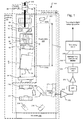
- the tunable laser subsystem 50 and clock subsystem 200 of the integrated laser clock system 100 are integrated together on a common optical bench 110.
- This bench is termed a micro-optical bench and is preferably less than 10 millimeters (mm) by 20 mm in size so that it fits within a standard butterfly or DIP (dual inline pin) hermetic package 101.
- the bench is fabricated from aluminum nitride.
- a thermoelectric cooler 102 is disposed between the bench 110 and the package 101 (attached/solder bonded both to the backside of the bench and inner bottom panel of the package 101) to control the temperature of the bench 110.
- the tunable laser 50 comprises a semiconductor gain chip 52 that is paired with a micro-electro-mechanical (MEMS) angled reflective Fabry-Perot tunable filter 54 to create external cavity laser (ECL) with the tunable filter 54 being an intracavity tuning element and forming one end, or back reflector, of a laser cavity 56 of the tunable ECL 50.
- MEMS micro-electro-mechanical
- ECL external cavity laser
- the semiconductor optical amplifier (SOA) chip 52 is located within the laser cavity 56.
- both facets of the SOA chip 52 are angled relative to a ridge waveguide 58 running longitudinally along the chip 52 and anti-reflection (AR) coated, providing parallel beams from the two facets.
- the SOA chip 52 is mounted on a submount 66 that, in turn, is mounted on the top side of the optical bench 110, typically by solder bonding.
- the first lens component 60 couples the light between the back facet of the SOA 52 and the tunable filter 54.
- Light exiting out the front facet of the SOA 52 is coupled by a second lens component 62 to optical fiber stub 64 via its front facet.
- the optical fiber stub 64 is also preferably solder attached to the optical bench 110 via a mounting structure m.
- the output optical fiber 64 is usually single spatial mode fiber (SMF).
- the optical fiber 64 transports the tunable signal to a coupler 65.
- the optical fiber terminates in a reflective coating 68, for a front reflector of the laser cavity 56, having between 1 and 85 percent reflectivity to feedback a portion of the tunable signal into the laser cavity 56.
- the light transmitted through the reflective coating 68 is transported to the optical coherence analysis system 300, see Fig. 3 , via fiber pigtail 320.
- the use of the fiber stub 64 in the cavity yield an ECL that has hybrid free space and fiber cavity, with the free space portion being implemented on the optical bench.
- the use of the stub 64 provides for control over the length of the laser cavity 56 by adjusting the length of the stub without necessitating changes to the portion of the optical cavity implemented on the bench 110.
- the cavity length 56 of the laser is selected in dependence upon the desired tuning speed: too long a cavity/fiber stub 64 may prevent the laser from lasing due to the transit time of light from the amplifier to the fiber exceeding the tunable filter bandwidth dwell time during a scan; but too short a fiber cavity will contain too few longitudinal modes in the laser emission defined by the linewidth of the tunable filter and contribute to high relative intensity noise (RIN) and tuning instability.
- fiber lengths vary from 30 centimeters (cm) to 3 cm.
- the angled reflective Fabry-Perot filter 54 is a multi-spatial-mode tunable filter having a curved-flat optical resonant cavity that provides angular-dependent, reflective spectral response back into the laser cavity 56. This effect is discussed in more detail in US 7,415,049 B2 .
- the curved mirror is on the MEMS membrane and is on the side of the filter 54 that adjoins the laser cavity 56.
- the flat mirror is on the opposite side and faces the laser cavity 56.
- the flat mirror preferably has a higher reflectivity than the curved mirror.
- the reflectivities for the flat and curved mirrors are typically 99.98% and 99.91%, respectively, in order to achieve the desired reflectivity and requisite linewidth of the filter 54 in reflection.
- the light transmitted by the tunable filter 54 is coupled out of the laser cavity 56 and into the clock subsystem 200 to be collimated by a third lens component 210 and a fourth lens component 212, which are solder bonded to the optical bench 110.
- Two fold mirrors 214 and 216 which are reflective coated substrates that are solder bonded to the bench 110, fold the beam of the light from the tunable laser subsystem 50, allowing for a dimensionally compact system.
- the light then passes through a beam splitter 222, which is preferably a 50/50 splitter to a clock etalon 220. Any light reflected by the splitter 222 is directed to a beam dump component 224 that absorbs the light and prevents parasitic reflections in the hermetic package 101 and into the laser cavity 56.
- a beam splitter 222 which is preferably a 50/50 splitter to a clock etalon 220. Any light reflected by the splitter 222 is directed to a beam dump component 224 that absorbs the light and prevents parasitic reflections in the hermetic package 101 and into the laser cavity 56.
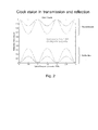
- the clock etalon 220 functions as a spectral filter. Its spectral features are periodic in frequency and spaced spectrally by a frequency increment related to the refractive index of the constituent material of the clock etalon 220, which is fused silica in one example, and the physical length L of the clock etalon 220.
- the etalon can alternatively be made of other high-index and transmissive materials such as silicon for compactness, but the optical dispersion of the material may need to be compensated for with additional processing inside the DSP. Also, air-gap etalons, which are nearly dispersionless, are another alternative.
- the contrast of the spectral features of the etalon is determined by the reflectivity of its opposed endfaces 220a, 220b.
- reflectivity at the etalon endfaces 220a, 220b is provided by the index of refraction discontinuity between the constituent material of the etalon and the surrounding gas or vacuum.
- the opposed endfaces 220a, 220b are coated with metal or preferably dielectric stack mirrors to provide higher reflectivity and thus contrast to the periodic spectral features.
- the clock etalon 220 is operated in reflection.
- Fig. 2 is a plot of reflection/transmission as a function of optical frequency in units of the free spectral range (FSR) of the etalon 220.
- FSR free spectral range
- the FSR of the clock etalon is chosen based on the required scanning depth in an OCT system.
- the Nyquist criterion dictates that the periodic frequency spacing of the clock etalon that defines the sample rate be half the smallest frequency period component of the sample, thus setting the optical thickness of the clock etalon to twice the required imaging depth.
- the periodic waveform can be electrically frequency doubled, tripled, etc, or can be halved to obtain the desired sample rate while choosing an etalon of a length that is convenient for handling and that easily fits within the package 101 and on the bench 110.
- a thicker etalon compensates better for nonlinear frequency scanning than a thinner one due to its finer sample rate, but it is larger and more difficult to fabricate, so a tradeoff is made depending upon the laser tuning linearity, system depth requirements, and manufacturing tolerances.
- a thicker etalon requires a laser of comparable coherence length to generate stable clock pulses, so the laser coherence length can also help dictate the design of the etalon thickness.
- the light returning from the clock etalon 220 and reflected by beamsplitter 222 is detected by detector 226.
- the light detected by detector 226 is characterized by drops and rises in power as the frequency of the tunable signal scans through the reflective troughs/reflective peaks provided by the clock etalon 220.
- the detector photocurrent is amplified with a transimpedance amplifier 310. Its signal is sent through a high-pass filter 312 to remove the direct current (DC) and other low-frequency components.
- the object of this processing is to provide an oscillating signal centered about zero Volts where the zero-crossings can be detected to generate a precise clock signal.
- Further shaping of the clock is provided by an amplifier 314, which can be a linear type, an automatic gain control type, or a limiting type amplifier.
- the amplifier 314 is followed by an optional fast comparator 316 to detect zero crossings and convert the analog signal to a clean digital clock signal.
- the clock signal is multiplied in frequency by multiplier 318, depending on the needs of the OCT system's application and the requirement for a convenient etalon (or other clock interferometer) size within the butterfly package 101.
- a frequency multiplier 318 is used to increase the sampling frequency to the multiple of the signal from the clocking detector. This is used in situations in which a higher sampling frequency is required.
- a frequency multiplier 318 is used in situations in which a higher sampling frequency is required.
- One case where it is advantageous is for applications that require a very deep scan range. For example, if a scan range of L is required, the etalon length would have to be at least 2L/n, where n is the refractive index. By installing frequency doubling electronics, the etalon length would only have to be L/n. This may make the difference between an etalon that fits inside the package and not.
- Another reason for using multiplication electronics is that it can increase stability of the clock signal for a given laser coherence length. The interference fringes are more stable for shorter etalon lengths.
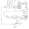
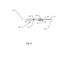
- Fig. 3 shows an example of how the laser/clock module 100 of Fig. 1 is used in one, exemplary optical coherence analysis system 300, and more specifically the Michelson interferometer that is used to analyze the optical signals from the sample.
- exemplary optical coherence analysis system 300 and more specifically the Michelson interferometer that is used to analyze the optical signals from the sample.
- Michelson interferometer that is used to analyze the optical signals from the sample.
- Many other OCT system interferometer configurations and sample probe optics can be used with the laser/clock module 100, however.
- the illustrated system is a time encoded Fourier domain optical coherence tomography system (TEFD-OCT).
- TEFD-OCT time encoded Fourier domain optical coherence tomography system
- the light from the tunable laser 50 is output on fiber 320 to a 90/10 optical coupler 322.
- the tunable signal is divided by the coupler 322 between a reference arm 326 and a sample arm 324 of the system.
- the external mirror 332 has an adjustable fiber to mirror distance (see arrow 334). This distance determines the depth range being imaged, i.e. the position in the sample 340 of the zero path length difference between the reference arm 326 and the sample arm 324. The distance is adjusted for different sampling probes and/or imaged samples. Light returning from the reference mirror 332 is returned to a reference arm circulator 342 and directed to the 50/50 fiber coupler 346.
- the scanning is implemented by moving the probe 336 relative to the sample 340 using a two (x-y) dimensional or three (x-y-z) dimensional positioner 337.
- the x-y-z scanning is implemented by moving the sample 340 relative to the probe 336.
- cylindrical scanning is implemented by rotating and axially moving the probe 336.
- the clock signal is produced by the clock subsystem 200 of the clock laser 100, and is further formed and conditioned by the transimpedance amplifier 310, high-pass filter 312, amplifier 314, optional fast comparator 316, and the multiplier 318 as described previously.
- the digital signal processor 380 performs a Fourier transform on the data in order to reconstruct the image and perform a 2D or 3D tomographic reconstruction of the sample 340. This information generated by the digital signal processor 380 is then displayed on a video monitor.
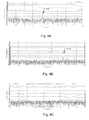
- Fig. 4A is a plot of laser pattern noise as a function of optical distance or depth, for example within the sample.
- optical distance means the equivalent distance in an air or vacuum.
- the corresponding physical distance is scaled by the refractive index of the transmission media, such as the sample.
- Artifact generated by peak 414 corresponding to the reflection between the tunable filter 54 and lens structure 60 is problematic if the sample distance overlaps this peak.
- One way to solve this potential problem is to reduce the magnitude of the spurious reflections and thus the magnitude of the spurious peak 414. However, sufficient reduction of the peak magnitude is not always possible.
- Another possible approach is to move this spurious peak to an optical distance location which is outside of the imaging range of interest.
- Fig. 1 shows a tunable laser with an optical path length extender element 70 inside the laser cavity 56.
- the extender element 70 is a transparent high refractive index material, such as fused silica or silicon or other transmissive material having a refractive index of about 2 or higher. Currently silicon is used. Both endfaces 72, 74 of the extender element 70 are antireflection coated. Further, the element is preferably angled by between 1 and 10 degrees relative to the optical axis of the tunable laser 50 to further spoil any reflections from the its endfaces 72, 74 from entering into the laser beam optical axis.
- the extender element 70 has the effect of moving the noise peak 414 in Fig. 4A to the right to correspond to greater depths within the sample 340 so that the laser pattern noise is now outside the depth of interest within the sample 340
- the semiconductor optical amplifier (SOA) 52 has gain in only one preferential polarization direction.
- light reflected from the fiber mirror coating 68 in the coupler 65 serves as one mirror of the laser cavity.
- single-mode fiber non polarization-maintaining
- PM polarization maintaining
- birefringence polarization state of the light
- stress from soldering the fiber further induces birefringence. In the worst-case instance, it can prevent lasing if the reflected light's direction of polarization ends up orthogonal to the preferred polarization state of the optical amplifier 52.
- Inserting a fiber polarization controller in the laser cavity 56 compensates by properly aligning the polarization state of the reflected light, but requires a long length of fiber and thus will not work with short fiber cavity lasers that are required for higher speed tuning.
- What is desired for a short fiber cavity is a device that allows for polarization alignment and fiber stability in a compact fixture, as shown in Fig. 5 and described below.
- the fiber stub 64 is held by two points in the coupler 65: 1) solder at point 418 connects fiber 64 to tube 420 that is the coupler's ferrule; and 2) by the mechanical splice between fiber 64 and fiber 320 at the optical coating/laser end reflector 68.
- a mechanical splice is the 3MTM FibrlokTM II Universal Optical Fiber Splice, which is mechanical splice that allows the coupling the highly reflective (HR) coated fiber 64 to the output fiber 320.
- HR highly reflective
- a fusion splice with an HR coating is used to couple fiber 64 to fiber 320.
- This mechanical splice is fixed within the body 422 typically by an epoxy bond.
- a cylindrical holder 424 is fixed to the body 422 and has in inner bore into which the tube 420 is inserted.
- a set screw 426 enables the tube 420 to be rotated relative to the cylindrical holder 424 and then fixed to the holder 424 when the set screw 426 is tightened down.
- an operator twists the fiber 64 by rotating the body 422 about the stainless steel tube 420.
- the output of the tunable laser operation is monitored by a detector connected to a high speed oscilloscope. Twisting of the fiber stub 64 induces polarization changes.
- the set screw 426 is tightened to fix the stress applied to the fiber.
- the stainless steel tube 420 prevents any subsequent fiber movement and thus maintains polarization stability.
- Fiber 64 is single mode fiber, because of bends in it and possibly stress at various points along its length, such as soldering points on the bench LIGA m and tube ferrule 420, has some small amount of resulting birefringence. This means that the light sent into the fiber from the gain chip 52 and bench 110 does not come back from the fiber-end mirror 68 necessarily in the same polarization as it was launched. By fixing the fiber 64 in this coupler 65, and rotating slightly the fiber, the polarization of the light returning from the mirror 68 is matched to the launch polarization. This polarization matching occurs over the whole wavelength tuning range of the laser 100. Any residual birefringence of the SMF fiber is small.
Landscapes
- Physics & Mathematics (AREA)
- General Physics & Mathematics (AREA)
- Electromagnetism (AREA)
- Optics & Photonics (AREA)
- Engineering & Computer Science (AREA)
- Condensed Matter Physics & Semiconductors (AREA)
- Plasma & Fusion (AREA)
- Radiology & Medical Imaging (AREA)
- Nuclear Medicine, Radiotherapy & Molecular Imaging (AREA)
- General Health & Medical Sciences (AREA)
- Health & Medical Sciences (AREA)
- Automation & Control Theory (AREA)
- Investigating Or Analysing Materials By Optical Means (AREA)
- Lasers (AREA)
- Instruments For Measurement Of Length By Optical Means (AREA)
- Length Measuring Devices By Optical Means (AREA)
Applications Claiming Priority (3)
| Application Number | Priority Date | Filing Date | Title |
|---|---|---|---|
| US5324108P | 2008-05-15 | 2008-05-15 | |
| US12/396,099 US8564783B2 (en) | 2008-05-15 | 2009-03-02 | Optical coherence tomography laser with integrated clock |
| PCT/US2009/044173 WO2009140614A2 (en) | 2008-05-15 | 2009-05-15 | Optical coherence tomography laser with integrated clock |
Publications (2)
| Publication Number | Publication Date |
|---|---|
| EP2286174A2 EP2286174A2 (en) | 2011-02-23 |
| EP2286174B1 true EP2286174B1 (en) | 2014-10-22 |
Family
ID=40886244
Family Applications (1)
| Application Number | Title | Priority Date | Filing Date |
|---|---|---|---|
| EP09747695.6A Active EP2286174B1 (en) | 2008-05-15 | 2009-05-15 | Optical coherence tomography laser with integrated clock |
Country Status (4)
| Country | Link |
|---|---|
| US (4) | US8564783B2 (enExample) |
| EP (1) | EP2286174B1 (enExample) |
| JP (2) | JP5497748B2 (enExample) |
| WO (1) | WO2009140614A2 (enExample) |
Families Citing this family (105)
| Publication number | Priority date | Publication date | Assignee | Title |
|---|---|---|---|---|
| US9867530B2 (en) | 2006-08-14 | 2018-01-16 | Volcano Corporation | Telescopic side port catheter device with imaging system and method for accessing side branch occlusions |
| US8395781B2 (en) | 2007-07-12 | 2013-03-12 | Volcano Corporation | Automatic calibration systems and methods of use |
| EP2171396B1 (en) * | 2007-07-12 | 2020-05-13 | Volcano Corporation | Apparatus and methods for uniform frequency sample clocking |
| US9596993B2 (en) | 2007-07-12 | 2017-03-21 | Volcano Corporation | Automatic calibration systems and methods of use |
| JP5524835B2 (ja) | 2007-07-12 | 2014-06-18 | ヴォルカノ コーポレイション | 生体内撮像用カテーテル |
| WO2009009802A1 (en) | 2007-07-12 | 2009-01-15 | Volcano Corporation | Oct-ivus catheter for concurrent luminal imaging |
| EP2677272B1 (en) | 2008-05-15 | 2018-01-31 | Axsun Technologies LLC | Oct combining probes and integrated systems |
| US8564783B2 (en) | 2008-05-15 | 2013-10-22 | Axsun Technologies, Inc. | Optical coherence tomography laser with integrated clock |
| US8457440B1 (en) | 2009-01-27 | 2013-06-04 | Axsun Technologies, Inc. | Method and system for background subtraction in medical optical coherence tomography system |
| US8139226B2 (en) * | 2009-04-28 | 2012-03-20 | Axsun Technologies, Inc. | Soft clock delay for OCT system and method therefor |
| US8693745B2 (en) | 2009-05-04 | 2014-04-08 | Duke University | Methods and computer program products for quantitative three-dimensional image correction and clinical parameter computation in optical coherence tomography |
| US8947670B2 (en) * | 2010-11-11 | 2015-02-03 | Thermo Electron Scientific Instruments Inc. | Flexure mounted moving mirror to reduce vibration noise |
| US11141063B2 (en) | 2010-12-23 | 2021-10-12 | Philips Image Guided Therapy Corporation | Integrated system architectures and methods of use |
| US10371499B2 (en) * | 2010-12-27 | 2019-08-06 | Axsun Technologies, Inc. | Laser swept source with controlled mode locking for OCT medical imaging |
| US20120162662A1 (en) * | 2010-12-27 | 2012-06-28 | Axsun Technologies, Inc. | Actively Mode Locked Laser Swept Source for OCT Medical Imaging |
| US8687666B2 (en) * | 2010-12-28 | 2014-04-01 | Axsun Technologies, Inc. | Integrated dual swept source for OCT medical imaging |
| US8437007B2 (en) | 2010-12-30 | 2013-05-07 | Axsun Technologies, Inc. | Integrated optical coherence tomography system |
| US9046337B2 (en) * | 2010-12-30 | 2015-06-02 | Volcano Corporation | Integrated OCT detector system with transimpedance amplifier |
| US11040140B2 (en) | 2010-12-31 | 2021-06-22 | Philips Image Guided Therapy Corporation | Deep vein thrombosis therapeutic methods |
| WO2012100213A2 (en) * | 2011-01-21 | 2012-07-26 | Duke University | Systems and methods for complex conjugate artifact resolved optical coherence tomography |
| DE102011011277B4 (de) | 2011-02-11 | 2024-05-08 | Carl Zeiss Meditec Ag | Optimierte Vorrichtung zur Swept Source Optical Coherence Domain Reflectometry und Tomography |
| US9360630B2 (en) | 2011-08-31 | 2016-06-07 | Volcano Corporation | Optical-electrical rotary joint and methods of use |
| JP5655805B2 (ja) * | 2012-03-21 | 2015-01-21 | 住友電気工業株式会社 | 光プローブおよび光学的測定方法 |
| US9243885B2 (en) | 2012-04-12 | 2016-01-26 | Axsun Technologies, LLC | Multi-speed OCT swept source with optimized k-clock |
| US9441944B2 (en) | 2012-05-16 | 2016-09-13 | Axsun Technologies Llc | Regenerative mode locked laser swept source for OCT medical imaging |
| EP2878045B1 (en) | 2012-07-27 | 2020-01-08 | Thorlabs, Inc. | Polarization stable widely tunable short cavity laser |
| US9292918B2 (en) | 2012-10-05 | 2016-03-22 | Volcano Corporation | Methods and systems for transforming luminal images |
| US20140100454A1 (en) | 2012-10-05 | 2014-04-10 | Volcano Corporation | Methods and systems for establishing parameters for three-dimensional imaging |
| US9367965B2 (en) | 2012-10-05 | 2016-06-14 | Volcano Corporation | Systems and methods for generating images of tissue |
| WO2014055880A2 (en) | 2012-10-05 | 2014-04-10 | David Welford | Systems and methods for amplifying light |
| US9307926B2 (en) | 2012-10-05 | 2016-04-12 | Volcano Corporation | Automatic stent detection |
| US10568586B2 (en) | 2012-10-05 | 2020-02-25 | Volcano Corporation | Systems for indicating parameters in an imaging data set and methods of use |
| US9858668B2 (en) | 2012-10-05 | 2018-01-02 | Volcano Corporation | Guidewire artifact removal in images |
| US9286673B2 (en) | 2012-10-05 | 2016-03-15 | Volcano Corporation | Systems for correcting distortions in a medical image and methods of use thereof |
| US11272845B2 (en) | 2012-10-05 | 2022-03-15 | Philips Image Guided Therapy Corporation | System and method for instant and automatic border detection |
| US9324141B2 (en) | 2012-10-05 | 2016-04-26 | Volcano Corporation | Removal of A-scan streaking artifact |
| US10070827B2 (en) | 2012-10-05 | 2018-09-11 | Volcano Corporation | Automatic image playback |
| US9840734B2 (en) | 2012-10-22 | 2017-12-12 | Raindance Technologies, Inc. | Methods for analyzing DNA |
| CA2894403A1 (en) | 2012-12-13 | 2014-06-19 | Volcano Corporation | Devices, systems, and methods for targeted cannulation |
| CA2895502A1 (en) | 2012-12-20 | 2014-06-26 | Jeremy Stigall | Smooth transition catheters |
| JP2016504589A (ja) | 2012-12-20 | 2016-02-12 | ナサニエル ジェイ. ケンプ, | 異なる撮像モード間で再構成可能な光コヒーレンストモグラフィシステム |
| US10942022B2 (en) | 2012-12-20 | 2021-03-09 | Philips Image Guided Therapy Corporation | Manual calibration of imaging system |
| US10939826B2 (en) | 2012-12-20 | 2021-03-09 | Philips Image Guided Therapy Corporation | Aspirating and removing biological material |
| US9730613B2 (en) | 2012-12-20 | 2017-08-15 | Volcano Corporation | Locating intravascular images |
| US11406498B2 (en) | 2012-12-20 | 2022-08-09 | Philips Image Guided Therapy Corporation | Implant delivery system and implants |
| EP2936426B1 (en) | 2012-12-21 | 2021-10-13 | Jason Spencer | System and method for graphical processing of medical data |
| EP2936626A4 (en) | 2012-12-21 | 2016-08-17 | David Welford | SYSTEMS AND METHOD FOR REDUCING A WAVELENGTH LIGHT EMISSION |
| US20140176958A1 (en) | 2012-12-21 | 2014-06-26 | Axsun Technologies, Inc. | OCT System with Bonded MEMS Tunable Mirror VCSEL Swept Source |
| CA2896004A1 (en) | 2012-12-21 | 2014-06-26 | Nathaniel J. Kemp | Power-efficient optical buffering using optical switch |
| WO2014100606A1 (en) | 2012-12-21 | 2014-06-26 | Meyer, Douglas | Rotational ultrasound imaging catheter with extended catheter body telescope |
| US10058284B2 (en) | 2012-12-21 | 2018-08-28 | Volcano Corporation | Simultaneous imaging, monitoring, and therapy |
| CA2895940A1 (en) | 2012-12-21 | 2014-06-26 | Andrew Hancock | System and method for multipath processing of image signals |
| US10413317B2 (en) | 2012-12-21 | 2019-09-17 | Volcano Corporation | System and method for catheter steering and operation |
| WO2014099760A1 (en) | 2012-12-21 | 2014-06-26 | Mai Jerome | Ultrasound imaging with variable line density |
| US9486143B2 (en) | 2012-12-21 | 2016-11-08 | Volcano Corporation | Intravascular forward imaging device |
| US9612105B2 (en) | 2012-12-21 | 2017-04-04 | Volcano Corporation | Polarization sensitive optical coherence tomography system |
| US10226597B2 (en) | 2013-03-07 | 2019-03-12 | Volcano Corporation | Guidewire with centering mechanism |
| JP6243453B2 (ja) | 2013-03-07 | 2017-12-06 | ボルケーノ コーポレイション | 血管内画像におけるマルチモーダルセグメンテーション |
| EP3895604A1 (en) | 2013-03-12 | 2021-10-20 | Collins, Donna | Systems and methods for diagnosing coronary microvascular disease |
| US20140276923A1 (en) | 2013-03-12 | 2014-09-18 | Volcano Corporation | Vibrating catheter and methods of use |
| JP6339170B2 (ja) | 2013-03-13 | 2018-06-06 | ジンヒョン パーク | 回転式血管内超音波装置から画像を生成するためのシステム及び方法 |
| US9301687B2 (en) | 2013-03-13 | 2016-04-05 | Volcano Corporation | System and method for OCT depth calibration |
| US11026591B2 (en) | 2013-03-13 | 2021-06-08 | Philips Image Guided Therapy Corporation | Intravascular pressure sensor calibration |
| US12343198B2 (en) | 2013-03-14 | 2025-07-01 | Philips Image Guided Therapy Corporation | Delivery catheter having imaging capabilities |
| US10292677B2 (en) | 2013-03-14 | 2019-05-21 | Volcano Corporation | Endoluminal filter having enhanced echogenic properties |
| US10426590B2 (en) | 2013-03-14 | 2019-10-01 | Volcano Corporation | Filters with echogenic characteristics |
| US10219887B2 (en) | 2013-03-14 | 2019-03-05 | Volcano Corporation | Filters with echogenic characteristics |
| US9488569B2 (en) | 2013-06-10 | 2016-11-08 | Florida Agricultural And Mechanical University | Method and systems to detect matter through use of a magnetic field gradient |
| US9310182B2 (en) | 2013-12-30 | 2016-04-12 | Axsun Technologies Llc | Spectral filtering of k-clock signal in OCT system and method |
| US9316483B2 (en) * | 2013-12-31 | 2016-04-19 | Axsun Technologies Llc | OCT swept laser with high coherence signal extraction |
| US9869542B2 (en) | 2014-04-21 | 2018-01-16 | Axsun Technologies, Inc. | System and method for resampling optical coherence tomography signals in segments |
| JP6357344B2 (ja) * | 2014-04-28 | 2018-07-11 | 株式会社トーメーコーポレーション | 眼寸法測定装置 |
| DK3172527T3 (da) | 2014-07-25 | 2024-05-27 | Excelitas Tech Corp | Fpga-gensampling i realtid for optisk swept-source-kohærenstomografi |
| JP6181013B2 (ja) * | 2014-08-08 | 2017-08-16 | 株式会社吉田製作所 | 光干渉断層画像生成装置及び光干渉断層画像生成方法 |
| US10105107B2 (en) | 2015-01-08 | 2018-10-23 | St. Jude Medical International Holding S.À R.L. | Medical system having combined and synergized data output from multiple independent inputs |
| US10705799B2 (en) | 2015-03-04 | 2020-07-07 | Carol Y. Scarlett | Transmission of information through the use of quantum-optical effects within a multi-layered birefringent structure |
| US10394525B2 (en) | 2015-03-04 | 2019-08-27 | Carol Y. Scarlett | Generation of random numbers through the use of quantum-optical effects within a multi-layered birefringent structure |
| EP3265906B1 (en) | 2015-03-04 | 2020-10-07 | Scarlett, Carol, Y. | Generation of random numbers through the use of quantum-optical effects within a mirror cavity system |
| US10211590B2 (en) * | 2015-11-25 | 2019-02-19 | Raytheon Company | Dual-function optical bench and cooling manifold for high-power laser system |
| US10297968B2 (en) | 2015-11-25 | 2019-05-21 | Raytheon Company | High-gain single planar waveguide (PWG) amplifier laser system |
| US11114813B2 (en) * | 2015-11-25 | 2021-09-07 | Raytheon Company | Integrated pumplight homogenizer and signal injector for high-power laser system |
| US10069270B2 (en) | 2016-02-11 | 2018-09-04 | Raytheon Company | Planar waveguides with enhanced support and/or cooling features for high-power laser systems |
| US20180149584A1 (en) | 2016-11-29 | 2018-05-31 | Carol Y. Scarlett | Circular birefringence identification of materials |
| CA3048197A1 (en) | 2016-12-21 | 2018-06-28 | Acucela Inc. | Miniaturized mobile, low cost optical coherence tomography system for home based ophthalmic applications |
| DE102017204478A1 (de) * | 2017-03-17 | 2018-09-20 | Jenoptik Laser Gmbh | Verfahren zum Betreiben eines oberflächenemittierenden Halbleiterlasers mit veränderlicher Wellenzahl |
| US10511135B2 (en) | 2017-12-19 | 2019-12-17 | Raytheon Company | Laser system with mechanically-robust monolithic fused planar waveguide (PWG) structure |
| DE112019002638T5 (de) * | 2018-05-24 | 2021-03-11 | Panasonic Intellectual Property Management Co., Ltd. | Austauschbare laser-resonator module mit winkelverstellung |
| JP7402866B2 (ja) | 2018-06-20 | 2023-12-21 | アキュセラ インコーポレイテッド | 家庭用眼科用途のための小型化モバイル低コスト光干渉断層撮影システム |
| US11133639B2 (en) | 2018-07-24 | 2021-09-28 | Raytheon Company | Fast axis thermal lens compensation for a planar amplifier structure |
| US11740071B2 (en) | 2018-12-21 | 2023-08-29 | Apple Inc. | Optical interferometry proximity sensor with temperature variation compensation |
| US11243068B1 (en) | 2019-02-28 | 2022-02-08 | Apple Inc. | Configuration and operation of array of self-mixing interferometry sensors |
| US11156456B2 (en) | 2019-05-21 | 2021-10-26 | Apple Inc. | Optical proximity sensor integrated into a camera module for an electronic device |
| US11473898B2 (en) | 2019-05-24 | 2022-10-18 | Apple Inc. | Wearable voice-induced vibration or silent gesture sensor |
| US11730363B2 (en) | 2019-12-26 | 2023-08-22 | Acucela Inc. | Optical coherence tomography patient alignment system for home based ophthalmic applications |
| US11150332B1 (en) | 2020-06-30 | 2021-10-19 | Apple Inc. | Self-calibrating optical transceiver system with reduced crosstalk sensitivity for through-display proximity sensing |
| US10959613B1 (en) | 2020-08-04 | 2021-03-30 | Acucela Inc. | Scan pattern and signal processing for optical coherence tomography |
| JP2023538542A (ja) | 2020-08-14 | 2023-09-08 | アキュセラ インコーポレイテッド | 光干渉断層撮影a走査のデカービングのためのシステムおよび方法 |
| US11393094B2 (en) | 2020-09-11 | 2022-07-19 | Acucela Inc. | Artificial intelligence for evaluation of optical coherence tomography images |
| US11874110B2 (en) | 2020-09-25 | 2024-01-16 | Apple Inc. | Self-mixing interferometry device configured for non-reciprocal sensing |
| US11460293B2 (en) | 2020-09-25 | 2022-10-04 | Apple Inc. | Surface quality sensing using self-mixing interferometry |
| US11911105B2 (en) | 2020-09-30 | 2024-02-27 | Acucela Inc. | Myopia prediction, diagnosis, planning, and monitoring device |
| US11629948B2 (en) | 2021-02-04 | 2023-04-18 | Apple Inc. | Optical interferometry proximity sensor with optical path extender |
| WO2022204622A1 (en) | 2021-03-24 | 2022-09-29 | Acucela Inc. | Axial length measurement monitor |
| US12209890B2 (en) | 2022-03-31 | 2025-01-28 | Apple Inc. | Optical sensor module including an interferometric sensor and extended depth of focus optics |
| CN115753607B (zh) * | 2022-11-02 | 2025-12-12 | 库力索法高科股份有限公司 | 具信号整形的扫频激光光源系统 |
Citations (3)
| Publication number | Priority date | Publication date | Assignee | Title |
|---|---|---|---|---|
| US20050083533A1 (en) * | 2003-10-17 | 2005-04-21 | Axsun Technologies, Inc. | Integrated spectroscopy system |
| US20060055936A1 (en) * | 2004-09-10 | 2006-03-16 | The General Hospital Corporation | System and method for optical coherence imaging |
| US20060232783A1 (en) * | 2005-01-20 | 2006-10-19 | Michael Choma | Methods and systems for reducing complex conjugat ambiguity in interferometric data |
Family Cites Families (34)
| Publication number | Priority date | Publication date | Assignee | Title |
|---|---|---|---|---|
| US3736040A (en) * | 1970-12-28 | 1973-05-29 | Trw Data Systems | Coherence extender for q-switched lasers for use in halography |
| US5956355A (en) * | 1991-04-29 | 1999-09-21 | Massachusetts Institute Of Technology | Method and apparatus for performing optical measurements using a rapidly frequency-tuned laser |
| US5659559A (en) * | 1994-06-28 | 1997-08-19 | Sdl, Inc. | Apparatus for generating a stabilized laser source |
| DE69527830T2 (de) * | 1994-11-14 | 2003-01-02 | Mitsui Chemicals, Inc. | Wellenlängenstabilisierter Lichtquelle |
| DE69626950D1 (de) * | 1996-01-12 | 2003-04-30 | Corning Oti Spa | Mit seltenen Erden dotierter Lithiumniobat-DBR-Laser |
| EP0880810A1 (en) * | 1996-02-13 | 1998-12-02 | Optical Corporation of America | External cavity semiconductor laser with monolithic prism assembly |
| US5914972A (en) * | 1997-03-24 | 1999-06-22 | Sdl, Inc. | Thermal compensators for waveguide DBR laser sources |
| JP3450180B2 (ja) | 1998-04-20 | 2003-09-22 | 日本電気株式会社 | 波長可変レーザー |
| US6658031B2 (en) * | 2001-07-06 | 2003-12-02 | Intel Corporation | Laser apparatus with active thermal tuning of external cavity |
| US6822979B2 (en) * | 2001-07-06 | 2004-11-23 | Intel Corporation | External cavity laser with continuous tuning of grid generator |
| US6763047B2 (en) | 2002-06-15 | 2004-07-13 | Intel Corporation | External cavity laser apparatus and methods |
| US6792010B2 (en) | 2002-12-20 | 2004-09-14 | Picarro, Inc. | Laser with reduced parasitic etalon effects |
| AU2004237243B2 (en) | 2003-05-05 | 2010-11-11 | D4D Technologies, Llc | Optical coherence tomography imaging |
| JP2004356504A (ja) | 2003-05-30 | 2004-12-16 | Picarro Inc | 寄生エタロンの影響を低減したレーザ |
| WO2005022709A1 (en) | 2003-08-27 | 2005-03-10 | Forskningscenter Risø | A continuously swept frequency laser source |
| US7130320B2 (en) * | 2003-11-13 | 2006-10-31 | Mitutoyo Corporation | External cavity laser with rotary tuning element |
| JP4409320B2 (ja) | 2004-03-19 | 2010-02-03 | 日本航空電子工業株式会社 | 可変光利得等化器および光利得等化装置 |
| US20060029110A1 (en) * | 2004-08-03 | 2006-02-09 | Imra America, Inc. | Cavity monitoring device for pulse laser |
| DE102004040735B4 (de) | 2004-08-23 | 2006-11-23 | ETH-Zürich, Institut für Lebensmittelwissenschaft, Laboratorium für Lebensmittelverfahrenstechnik | Verfahren zur mechanisch schonenden Erzeugung von fein dispersen Mikro-/Nano-Emulsionen mit enger Tropfengrößenverteilung und Vorrichtung zum Durchführen des Verfahrens |
| US7060967B2 (en) * | 2004-10-12 | 2006-06-13 | Optoplan As | Optical wavelength interrogator |
| US7415049B2 (en) * | 2005-03-28 | 2008-08-19 | Axsun Technologies, Inc. | Laser with tilted multi spatial mode resonator tuning element |
| WO2006130802A2 (en) | 2005-06-01 | 2006-12-07 | The General Hospital Corporation | Apparatus, method and system for performing phase-resolved optical frequency domain imaging |
| WO2007004509A1 (ja) | 2005-07-01 | 2007-01-11 | Nec Corporation | 外部共振器型波長可変レーザ装置および光出力モジュール |
| JP4376837B2 (ja) * | 2005-08-05 | 2009-12-02 | サンテック株式会社 | 波長走査型レーザ光源 |
| JP2007101249A (ja) * | 2005-09-30 | 2007-04-19 | Fujifilm Corp | 光断層画像化方法および装置 |
| JP2007260123A (ja) | 2006-03-28 | 2007-10-11 | Olympus Medical Systems Corp | 撮像システムおよび撮像方法 |
| WO2007105495A1 (ja) * | 2006-03-13 | 2007-09-20 | Olympus Medical Systems Corp. | 散乱媒質内部観察装置、撮像システム、撮像方法及び内視鏡装置 |
| JP2008070350A (ja) | 2006-08-15 | 2008-03-27 | Fujifilm Corp | 光断層画像化装置 |
| US7916387B2 (en) | 2007-01-10 | 2011-03-29 | Lightlab Imaging, Inc. | Methods and apparatus for swept-source optical coherence tomography |
| EP2171396B1 (en) | 2007-07-12 | 2020-05-13 | Volcano Corporation | Apparatus and methods for uniform frequency sample clocking |
| US20090059971A1 (en) * | 2007-08-27 | 2009-03-05 | Axsun Technologies, Inc. | Linearized Swept Laser Source for Optical Coherence Analysis System |
| JP2009252813A (ja) | 2008-04-02 | 2009-10-29 | Fujifilm Corp | 光源および光断層画像化装置 |
| US8564783B2 (en) | 2008-05-15 | 2013-10-22 | Axsun Technologies, Inc. | Optical coherence tomography laser with integrated clock |
| US8392138B2 (en) * | 2008-08-08 | 2013-03-05 | The Regents Of The University Of Colorado | System and method for correcting sampling errors associated with radiation source tuning rate fluctuations in swept-wavelength interferometry |
-
2009
- 2009-03-02 US US12/396,099 patent/US8564783B2/en active Active
- 2009-05-15 JP JP2011509756A patent/JP5497748B2/ja active Active
- 2009-05-15 WO PCT/US2009/044173 patent/WO2009140614A2/en not_active Ceased
- 2009-05-15 EP EP09747695.6A patent/EP2286174B1/en active Active
-
2013
- 2013-09-17 US US14/028,873 patent/US9417051B2/en active Active
-
2014
- 2014-03-06 JP JP2014043714A patent/JP5934270B2/ja active Active
-
2016
- 2016-07-08 US US15/205,888 patent/US9791261B2/en active Active
-
2017
- 2017-10-16 US US15/785,142 patent/US10184783B2/en active Active
Patent Citations (3)
| Publication number | Priority date | Publication date | Assignee | Title |
|---|---|---|---|---|
| US20050083533A1 (en) * | 2003-10-17 | 2005-04-21 | Axsun Technologies, Inc. | Integrated spectroscopy system |
| US20060055936A1 (en) * | 2004-09-10 | 2006-03-16 | The General Hospital Corporation | System and method for optical coherence imaging |
| US20060232783A1 (en) * | 2005-01-20 | 2006-10-19 | Michael Choma | Methods and systems for reducing complex conjugat ambiguity in interferometric data |
Also Published As
| Publication number | Publication date |
|---|---|
| WO2009140614A3 (en) | 2010-03-18 |
| US10184783B2 (en) | 2019-01-22 |
| US20090290167A1 (en) | 2009-11-26 |
| US9417051B2 (en) | 2016-08-16 |
| US8564783B2 (en) | 2013-10-22 |
| EP2286174A2 (en) | 2011-02-23 |
| JP2014098723A (ja) | 2014-05-29 |
| US20140016135A1 (en) | 2014-01-16 |
| US20180051978A1 (en) | 2018-02-22 |
| JP5934270B2 (ja) | 2016-06-15 |
| JP5497748B2 (ja) | 2014-05-21 |
| US20160320172A1 (en) | 2016-11-03 |
| US9791261B2 (en) | 2017-10-17 |
| WO2009140614A2 (en) | 2009-11-19 |
| JP2011524003A (ja) | 2011-08-25 |
Similar Documents
| Publication | Publication Date | Title |
|---|---|---|
| EP2286174B1 (en) | Optical coherence tomography laser with integrated clock | |
| US9593934B2 (en) | Integrated dual swept source for OCT medical imaging | |
| US11092426B2 (en) | Integrated optical coherence analysis system | |
| JP5898077B2 (ja) | Oct医療用画像化のためのフィルタase掃引源 | |
| US8670129B2 (en) | Filtered ASE swept source for OCT medical imaging | |
| US5956355A (en) | Method and apparatus for performing optical measurements using a rapidly frequency-tuned laser | |
| US8665450B2 (en) | Integrated dual swept source for OCT medical imaging | |
| US8660164B2 (en) | Method and system for avoiding package induced failure in swept semiconductor source | |
| US8059277B2 (en) | Mode hopping swept frequency laser for FD OCT and method of operation | |
| EP2659223B1 (en) | Integrated optical coherence tomography system | |
| US9784561B2 (en) | Optical coherence tomography imaging system and method | |
| US20110255095A1 (en) | Optical Coherence Tomography Imaging System and Method |
Legal Events
| Date | Code | Title | Description |
|---|---|---|---|
| PUAI | Public reference made under article 153(3) epc to a published international application that has entered the european phase |
Free format text: ORIGINAL CODE: 0009012 |
|
| AK | Designated contracting states |
Kind code of ref document: A2 Designated state(s): AT BE BG CH CY CZ DE DK EE ES FI FR GB GR HR HU IE IS IT LI LT LU LV MC MK MT NL NO PL PT RO SE SI SK TR |
|
| AX | Request for extension of the european patent |
Extension state: AL BA RS |
|
| 17P | Request for examination filed |
Effective date: 20101213 |
|
| DAX | Request for extension of the european patent (deleted) | ||
| 17Q | First examination report despatched |
Effective date: 20130103 |
|
| GRAP | Despatch of communication of intention to grant a patent |
Free format text: ORIGINAL CODE: EPIDOSNIGR1 |
|
| INTG | Intention to grant announced |
Effective date: 20140604 |
|
| GRAS | Grant fee paid |
Free format text: ORIGINAL CODE: EPIDOSNIGR3 |
|
| GRAA | (expected) grant |
Free format text: ORIGINAL CODE: 0009210 |
|
| AK | Designated contracting states |
Kind code of ref document: B1 Designated state(s): AT BE BG CH CY CZ DE DK EE ES FI FR GB GR HR HU IE IS IT LI LT LU LV MC MK MT NL NO PL PT RO SE SI SK TR |
|
| REG | Reference to a national code |
Ref country code: GB Ref legal event code: FG4D |
|
| REG | Reference to a national code |
Ref country code: CH Ref legal event code: EP |
|
| REG | Reference to a national code |
Ref country code: AT Ref legal event code: REF Ref document number: 692861 Country of ref document: AT Kind code of ref document: T Effective date: 20141115 |
|
| REG | Reference to a national code |
Ref country code: IE Ref legal event code: FG4D |
|
| REG | Reference to a national code |
Ref country code: DE Ref legal event code: R096 Ref document number: 602009027324 Country of ref document: DE Effective date: 20141204 |
|
| REG | Reference to a national code |
Ref country code: NL Ref legal event code: VDEP Effective date: 20141022 |
|
| REG | Reference to a national code |
Ref country code: AT Ref legal event code: MK05 Ref document number: 692861 Country of ref document: AT Kind code of ref document: T Effective date: 20141022 |
|
| REG | Reference to a national code |
Ref country code: LT Ref legal event code: MG4D |
|
| PG25 | Lapsed in a contracting state [announced via postgrant information from national office to epo] |
Ref country code: NO Free format text: LAPSE BECAUSE OF FAILURE TO SUBMIT A TRANSLATION OF THE DESCRIPTION OR TO PAY THE FEE WITHIN THE PRESCRIBED TIME-LIMIT Effective date: 20150122 Ref country code: IS Free format text: LAPSE BECAUSE OF FAILURE TO SUBMIT A TRANSLATION OF THE DESCRIPTION OR TO PAY THE FEE WITHIN THE PRESCRIBED TIME-LIMIT Effective date: 20150222 Ref country code: PT Free format text: LAPSE BECAUSE OF FAILURE TO SUBMIT A TRANSLATION OF THE DESCRIPTION OR TO PAY THE FEE WITHIN THE PRESCRIBED TIME-LIMIT Effective date: 20150223 Ref country code: ES Free format text: LAPSE BECAUSE OF FAILURE TO SUBMIT A TRANSLATION OF THE DESCRIPTION OR TO PAY THE FEE WITHIN THE PRESCRIBED TIME-LIMIT Effective date: 20141022 Ref country code: LT Free format text: LAPSE BECAUSE OF FAILURE TO SUBMIT A TRANSLATION OF THE DESCRIPTION OR TO PAY THE FEE WITHIN THE PRESCRIBED TIME-LIMIT Effective date: 20141022 Ref country code: FI Free format text: LAPSE BECAUSE OF FAILURE TO SUBMIT A TRANSLATION OF THE DESCRIPTION OR TO PAY THE FEE WITHIN THE PRESCRIBED TIME-LIMIT Effective date: 20141022 Ref country code: NL Free format text: LAPSE BECAUSE OF FAILURE TO SUBMIT A TRANSLATION OF THE DESCRIPTION OR TO PAY THE FEE WITHIN THE PRESCRIBED TIME-LIMIT Effective date: 20141022 |
|
| PG25 | Lapsed in a contracting state [announced via postgrant information from national office to epo] |
Ref country code: CY Free format text: LAPSE BECAUSE OF FAILURE TO SUBMIT A TRANSLATION OF THE DESCRIPTION OR TO PAY THE FEE WITHIN THE PRESCRIBED TIME-LIMIT Effective date: 20141022 Ref country code: HR Free format text: LAPSE BECAUSE OF FAILURE TO SUBMIT A TRANSLATION OF THE DESCRIPTION OR TO PAY THE FEE WITHIN THE PRESCRIBED TIME-LIMIT Effective date: 20141022 Ref country code: SE Free format text: LAPSE BECAUSE OF FAILURE TO SUBMIT A TRANSLATION OF THE DESCRIPTION OR TO PAY THE FEE WITHIN THE PRESCRIBED TIME-LIMIT Effective date: 20141022 Ref country code: PL Free format text: LAPSE BECAUSE OF FAILURE TO SUBMIT A TRANSLATION OF THE DESCRIPTION OR TO PAY THE FEE WITHIN THE PRESCRIBED TIME-LIMIT Effective date: 20141022 Ref country code: GR Free format text: LAPSE BECAUSE OF FAILURE TO SUBMIT A TRANSLATION OF THE DESCRIPTION OR TO PAY THE FEE WITHIN THE PRESCRIBED TIME-LIMIT Effective date: 20150123 Ref country code: LV Free format text: LAPSE BECAUSE OF FAILURE TO SUBMIT A TRANSLATION OF THE DESCRIPTION OR TO PAY THE FEE WITHIN THE PRESCRIBED TIME-LIMIT Effective date: 20141022 Ref country code: AT Free format text: LAPSE BECAUSE OF FAILURE TO SUBMIT A TRANSLATION OF THE DESCRIPTION OR TO PAY THE FEE WITHIN THE PRESCRIBED TIME-LIMIT Effective date: 20141022 |
|
| REG | Reference to a national code |
Ref country code: DE Ref legal event code: R097 Ref document number: 602009027324 Country of ref document: DE |
|
| PG25 | Lapsed in a contracting state [announced via postgrant information from national office to epo] |
Ref country code: SK Free format text: LAPSE BECAUSE OF FAILURE TO SUBMIT A TRANSLATION OF THE DESCRIPTION OR TO PAY THE FEE WITHIN THE PRESCRIBED TIME-LIMIT Effective date: 20141022 Ref country code: CZ Free format text: LAPSE BECAUSE OF FAILURE TO SUBMIT A TRANSLATION OF THE DESCRIPTION OR TO PAY THE FEE WITHIN THE PRESCRIBED TIME-LIMIT Effective date: 20141022 Ref country code: DK Free format text: LAPSE BECAUSE OF FAILURE TO SUBMIT A TRANSLATION OF THE DESCRIPTION OR TO PAY THE FEE WITHIN THE PRESCRIBED TIME-LIMIT Effective date: 20141022 Ref country code: RO Free format text: LAPSE BECAUSE OF FAILURE TO SUBMIT A TRANSLATION OF THE DESCRIPTION OR TO PAY THE FEE WITHIN THE PRESCRIBED TIME-LIMIT Effective date: 20141022 Ref country code: EE Free format text: LAPSE BECAUSE OF FAILURE TO SUBMIT A TRANSLATION OF THE DESCRIPTION OR TO PAY THE FEE WITHIN THE PRESCRIBED TIME-LIMIT Effective date: 20141022 |
|
| PLBE | No opposition filed within time limit |
Free format text: ORIGINAL CODE: 0009261 |
|
| STAA | Information on the status of an ep patent application or granted ep patent |
Free format text: STATUS: NO OPPOSITION FILED WITHIN TIME LIMIT |
|
| PG25 | Lapsed in a contracting state [announced via postgrant information from national office to epo] |
Ref country code: IT Free format text: LAPSE BECAUSE OF FAILURE TO SUBMIT A TRANSLATION OF THE DESCRIPTION OR TO PAY THE FEE WITHIN THE PRESCRIBED TIME-LIMIT Effective date: 20141022 |
|
| 26N | No opposition filed |
Effective date: 20150723 |
|
| REG | Reference to a national code |
Ref country code: CH Ref legal event code: PL |
|
| PG25 | Lapsed in a contracting state [announced via postgrant information from national office to epo] |
Ref country code: MC Free format text: LAPSE BECAUSE OF FAILURE TO SUBMIT A TRANSLATION OF THE DESCRIPTION OR TO PAY THE FEE WITHIN THE PRESCRIBED TIME-LIMIT Effective date: 20141022 Ref country code: LU Free format text: LAPSE BECAUSE OF FAILURE TO SUBMIT A TRANSLATION OF THE DESCRIPTION OR TO PAY THE FEE WITHIN THE PRESCRIBED TIME-LIMIT Effective date: 20150515 Ref country code: LI Free format text: LAPSE BECAUSE OF NON-PAYMENT OF DUE FEES Effective date: 20150531 Ref country code: CH Free format text: LAPSE BECAUSE OF NON-PAYMENT OF DUE FEES Effective date: 20150531 |
|
| REG | Reference to a national code |
Ref country code: IE Ref legal event code: MM4A |
|
| REG | Reference to a national code |
Ref country code: FR Ref legal event code: ST Effective date: 20160129 |
|
| PG25 | Lapsed in a contracting state [announced via postgrant information from national office to epo] |
Ref country code: SI Free format text: LAPSE BECAUSE OF FAILURE TO SUBMIT A TRANSLATION OF THE DESCRIPTION OR TO PAY THE FEE WITHIN THE PRESCRIBED TIME-LIMIT Effective date: 20141022 |
|
| REG | Reference to a national code |
Ref country code: DE Ref legal event code: R082 Ref document number: 602009027324 Country of ref document: DE Representative=s name: HGF EUROPE LLP, DE Ref country code: DE Ref legal event code: R082 Ref document number: 602009027324 Country of ref document: DE Representative=s name: HGF EUROPE LP, DE Ref country code: DE Ref legal event code: R081 Ref document number: 602009027324 Country of ref document: DE Owner name: EXCELITAS TECHNOLOGIES CORP., WALTHAM, US Free format text: FORMER OWNER: AXSUN TECHNOLOGIES, INC., BILLERICA, MASS., US Ref country code: DE Ref legal event code: R082 Ref document number: 602009027324 Country of ref document: DE Representative=s name: PATRONUS IP PATENT- & RECHTSANWAELTE BERNHARD , DE Ref country code: DE Ref legal event code: R081 Ref document number: 602009027324 Country of ref document: DE Owner name: AXSUN TECHNOLOGIES LLC (N.D.GES.D. STAATES DEL, US Free format text: FORMER OWNER: AXSUN TECHNOLOGIES, INC., BILLERICA, MASS., US |
|
| PG25 | Lapsed in a contracting state [announced via postgrant information from national office to epo] |
Ref country code: IE Free format text: LAPSE BECAUSE OF NON-PAYMENT OF DUE FEES Effective date: 20150515 |
|
| PG25 | Lapsed in a contracting state [announced via postgrant information from national office to epo] |
Ref country code: FR Free format text: LAPSE BECAUSE OF NON-PAYMENT OF DUE FEES Effective date: 20150601 |
|
| PG25 | Lapsed in a contracting state [announced via postgrant information from national office to epo] |
Ref country code: MT Free format text: LAPSE BECAUSE OF FAILURE TO SUBMIT A TRANSLATION OF THE DESCRIPTION OR TO PAY THE FEE WITHIN THE PRESCRIBED TIME-LIMIT Effective date: 20141022 |
|
| PG25 | Lapsed in a contracting state [announced via postgrant information from national office to epo] |
Ref country code: HU Free format text: LAPSE BECAUSE OF FAILURE TO SUBMIT A TRANSLATION OF THE DESCRIPTION OR TO PAY THE FEE WITHIN THE PRESCRIBED TIME-LIMIT; INVALID AB INITIO Effective date: 20090515 Ref country code: BG Free format text: LAPSE BECAUSE OF FAILURE TO SUBMIT A TRANSLATION OF THE DESCRIPTION OR TO PAY THE FEE WITHIN THE PRESCRIBED TIME-LIMIT Effective date: 20141022 |
|
| PG25 | Lapsed in a contracting state [announced via postgrant information from national office to epo] |
Ref country code: TR Free format text: LAPSE BECAUSE OF FAILURE TO SUBMIT A TRANSLATION OF THE DESCRIPTION OR TO PAY THE FEE WITHIN THE PRESCRIBED TIME-LIMIT Effective date: 20141022 |
|
| PG25 | Lapsed in a contracting state [announced via postgrant information from national office to epo] |
Ref country code: BE Free format text: LAPSE BECAUSE OF FAILURE TO SUBMIT A TRANSLATION OF THE DESCRIPTION OR TO PAY THE FEE WITHIN THE PRESCRIBED TIME-LIMIT Effective date: 20141022 |
|
| PG25 | Lapsed in a contracting state [announced via postgrant information from national office to epo] |
Ref country code: MK Free format text: LAPSE BECAUSE OF FAILURE TO SUBMIT A TRANSLATION OF THE DESCRIPTION OR TO PAY THE FEE WITHIN THE PRESCRIBED TIME-LIMIT Effective date: 20141022 |
|
| REG | Reference to a national code |
Ref country code: GB Ref legal event code: 732E Free format text: REGISTERED BETWEEN 20210204 AND 20210210 |
|
| REG | Reference to a national code |
Ref country code: DE Ref legal event code: R082 Ref document number: 602009027324 Country of ref document: DE Representative=s name: HGF EUROPE LLP, DE Ref country code: DE Ref legal event code: R081 Ref document number: 602009027324 Country of ref document: DE Owner name: EXCELITAS TECHNOLOGIES CORP., WALTHAM, US Free format text: FORMER OWNER: AXSUN TECHNOLOGIES LLC (N.D.GES.D. STAATES DELAWARE), BILLERICA, MASS., US |
|
| P01 | Opt-out of the competence of the unified patent court (upc) registered |
Effective date: 20230529 |
|
| P02 | Opt-out of the competence of the unified patent court (upc) changed |
Effective date: 20230601 |
|
| PGFP | Annual fee paid to national office [announced via postgrant information from national office to epo] |
Ref country code: DE Payment date: 20250529 Year of fee payment: 17 |
|
| PGFP | Annual fee paid to national office [announced via postgrant information from national office to epo] |
Ref country code: GB Payment date: 20250527 Year of fee payment: 17 |