EP2284349B1 - Rahmenbaugruppe für ein Fenster oder eine Tür - Google Patents
Rahmenbaugruppe für ein Fenster oder eine Tür Download PDFInfo
- Publication number
- EP2284349B1 EP2284349B1 EP09008948.3A EP09008948A EP2284349B1 EP 2284349 B1 EP2284349 B1 EP 2284349B1 EP 09008948 A EP09008948 A EP 09008948A EP 2284349 B1 EP2284349 B1 EP 2284349B1
- Authority
- EP
- European Patent Office
- Prior art keywords
- sealing element
- groove
- profile
- window
- welding
- Prior art date
- Legal status (The legal status is an assumption and is not a legal conclusion. Google has not performed a legal analysis and makes no representation as to the accuracy of the status listed.)
- Active
Links
- 238000007789 sealing Methods 0.000 claims description 97
- 239000000463 material Substances 0.000 claims description 29
- 239000011521 glass Substances 0.000 claims description 6
- 239000004033 plastic Substances 0.000 description 65
- 238000003466 welding Methods 0.000 description 43
- 230000000712 assembly Effects 0.000 description 16
- 238000000429 assembly Methods 0.000 description 16
- 238000000034 method Methods 0.000 description 12
- 238000005520 cutting process Methods 0.000 description 10
- 239000011324 bead Substances 0.000 description 5
- 238000004519 manufacturing process Methods 0.000 description 5
- 229920001169 thermoplastic Polymers 0.000 description 5
- 239000004416 thermosoftening plastic Substances 0.000 description 5
- 239000013013 elastic material Substances 0.000 description 3
- 239000013536 elastomeric material Substances 0.000 description 3
- 238000005304 joining Methods 0.000 description 3
- 238000005096 rolling process Methods 0.000 description 3
- 230000003628 erosive effect Effects 0.000 description 2
- 238000001125 extrusion Methods 0.000 description 2
- 238000003860 storage Methods 0.000 description 2
- 239000012815 thermoplastic material Substances 0.000 description 2
- 230000002411 adverse Effects 0.000 description 1
- 238000004873 anchoring Methods 0.000 description 1
- 230000015572 biosynthetic process Effects 0.000 description 1
- 238000004140 cleaning Methods 0.000 description 1
- 238000010276 construction Methods 0.000 description 1
- 230000001419 dependent effect Effects 0.000 description 1
- 230000007257 malfunction Effects 0.000 description 1
- 238000003801 milling Methods 0.000 description 1
- 238000000465 moulding Methods 0.000 description 1
- 230000003287 optical effect Effects 0.000 description 1
- 238000003825 pressing Methods 0.000 description 1
Images

Classifications
-
- E—FIXED CONSTRUCTIONS
- E06—DOORS, WINDOWS, SHUTTERS, OR ROLLER BLINDS IN GENERAL; LADDERS
- E06B—FIXED OR MOVABLE CLOSURES FOR OPENINGS IN BUILDINGS, VEHICLES, FENCES OR LIKE ENCLOSURES IN GENERAL, e.g. DOORS, WINDOWS, BLINDS, GATES
- E06B3/00—Window sashes, door leaves, or like elements for closing wall or like openings; Layout of fixed or moving closures, e.g. windows in wall or like openings; Features of rigidly-mounted outer frames relating to the mounting of wing frames
- E06B3/96—Corner joints or edge joints for windows, doors, or the like frames or wings
- E06B3/9604—Welded or soldered joints
- E06B3/9608—Mitre joints
-
- E—FIXED CONSTRUCTIONS
- E06—DOORS, WINDOWS, SHUTTERS, OR ROLLER BLINDS IN GENERAL; LADDERS
- E06B—FIXED OR MOVABLE CLOSURES FOR OPENINGS IN BUILDINGS, VEHICLES, FENCES OR LIKE ENCLOSURES IN GENERAL, e.g. DOORS, WINDOWS, BLINDS, GATES
- E06B3/00—Window sashes, door leaves, or like elements for closing wall or like openings; Layout of fixed or moving closures, e.g. windows in wall or like openings; Features of rigidly-mounted outer frames relating to the mounting of wing frames
- E06B3/96—Corner joints or edge joints for windows, doors, or the like frames or wings
- E06B3/9616—Corner joints or edge joints for windows, doors, or the like frames or wings characterised by the sealing at the junction of the frame members
- E06B3/962—Mitre joints
-
- B—PERFORMING OPERATIONS; TRANSPORTING
- B29—WORKING OF PLASTICS; WORKING OF SUBSTANCES IN A PLASTIC STATE IN GENERAL
- B29C—SHAPING OR JOINING OF PLASTICS; SHAPING OF MATERIAL IN A PLASTIC STATE, NOT OTHERWISE PROVIDED FOR; AFTER-TREATMENT OF THE SHAPED PRODUCTS, e.g. REPAIRING
- B29C65/00—Joining or sealing of preformed parts, e.g. welding of plastics materials; Apparatus therefor
- B29C65/02—Joining or sealing of preformed parts, e.g. welding of plastics materials; Apparatus therefor by heating, with or without pressure
- B29C65/18—Joining or sealing of preformed parts, e.g. welding of plastics materials; Apparatus therefor by heating, with or without pressure using heated tools
- B29C65/20—Joining or sealing of preformed parts, e.g. welding of plastics materials; Apparatus therefor by heating, with or without pressure using heated tools with direct contact, e.g. using "mirror"
-
- B—PERFORMING OPERATIONS; TRANSPORTING
- B29—WORKING OF PLASTICS; WORKING OF SUBSTANCES IN A PLASTIC STATE IN GENERAL
- B29C—SHAPING OR JOINING OF PLASTICS; SHAPING OF MATERIAL IN A PLASTIC STATE, NOT OTHERWISE PROVIDED FOR; AFTER-TREATMENT OF THE SHAPED PRODUCTS, e.g. REPAIRING
- B29C66/00—General aspects of processes or apparatus for joining preformed parts
- B29C66/01—General aspects dealing with the joint area or with the area to be joined
- B29C66/05—Particular design of joint configurations
- B29C66/10—Particular design of joint configurations particular design of the joint cross-sections
- B29C66/11—Joint cross-sections comprising a single joint-segment, i.e. one of the parts to be joined comprising a single joint-segment in the joint cross-section
- B29C66/116—Single bevelled joints, i.e. one of the parts to be joined being bevelled in the joint area
- B29C66/1162—Single bevel to bevel joints, e.g. mitre joints
-
- B—PERFORMING OPERATIONS; TRANSPORTING
- B29—WORKING OF PLASTICS; WORKING OF SUBSTANCES IN A PLASTIC STATE IN GENERAL
- B29C—SHAPING OR JOINING OF PLASTICS; SHAPING OF MATERIAL IN A PLASTIC STATE, NOT OTHERWISE PROVIDED FOR; AFTER-TREATMENT OF THE SHAPED PRODUCTS, e.g. REPAIRING
- B29C66/00—General aspects of processes or apparatus for joining preformed parts
- B29C66/01—General aspects dealing with the joint area or with the area to be joined
- B29C66/32—Measures for keeping the burr form under control; Avoiding burr formation; Shaping the burr
-
- B—PERFORMING OPERATIONS; TRANSPORTING
- B29—WORKING OF PLASTICS; WORKING OF SUBSTANCES IN A PLASTIC STATE IN GENERAL
- B29C—SHAPING OR JOINING OF PLASTICS; SHAPING OF MATERIAL IN A PLASTIC STATE, NOT OTHERWISE PROVIDED FOR; AFTER-TREATMENT OF THE SHAPED PRODUCTS, e.g. REPAIRING
- B29C66/00—General aspects of processes or apparatus for joining preformed parts
- B29C66/50—General aspects of joining tubular articles; General aspects of joining long products, i.e. bars or profiled elements; General aspects of joining single elements to tubular articles, hollow articles or bars; General aspects of joining several hollow-preforms to form hollow or tubular articles
- B29C66/51—Joining tubular articles, profiled elements or bars; Joining single elements to tubular articles, hollow articles or bars; Joining several hollow-preforms to form hollow or tubular articles
- B29C66/52—Joining tubular articles, bars or profiled elements
- B29C66/524—Joining profiled elements
- B29C66/5243—Joining profiled elements for forming corner connections, e.g. for making window frames or V-shaped pieces
- B29C66/52431—Joining profiled elements for forming corner connections, e.g. for making window frames or V-shaped pieces with a right angle, e.g. for making L-shaped pieces
-
- B—PERFORMING OPERATIONS; TRANSPORTING
- B29—WORKING OF PLASTICS; WORKING OF SUBSTANCES IN A PLASTIC STATE IN GENERAL
- B29L—INDEXING SCHEME ASSOCIATED WITH SUBCLASS B29C, RELATING TO PARTICULAR ARTICLES
- B29L2031/00—Other particular articles
- B29L2031/001—Profiled members, e.g. beams, sections
- B29L2031/003—Profiled members, e.g. beams, sections having a profiled transverse cross-section
- B29L2031/005—Profiled members, e.g. beams, sections having a profiled transverse cross-section for making window frames
- B29L2031/006—Profiled members, e.g. beams, sections having a profiled transverse cross-section for making window frames and provided with a sealing element
Definitions
- the present invention relates to a frame assembly for a window and / or door comprising at least one plastic profile, which has an external flashover with at least one hollow chamber, a receiving portion and arranged on the outer flash groove for receiving a sealing element and a retracted into the groove sealing element, wherein a plane formed by the open side of the groove of the plastic profile is chamfered against a normal to the underside of the plastic profile.
- plastic profiles for doors and windows have an external flashover on which a sealing element is located. After the welding of the plastic profiles to frame assemblies for doors or windows, such a sealing element framed by a used in the frame surface support element, wherein the sealing element serves to seal the surface support member relative to the plastic profile.
- the plastic profiles cut to length and mitred at their ends are first plasticized on their miter joints with a welding mirror.
- elevated temperature for example in the range of 250-270 ° C.
- plasticizing the welding mirror is removed from the opposite end faces of the plastic profiles and then the plasticized end faces of the plastic profiles are under defined pressure for a pressed against each other for a certain period of time, whereby the plastic profiles are welded together at their miter joints. This creates at the miter joints so-called.
- welding beads or welding erosion
- sealing elements can then be continuously embedded in the respective receiving grooves of the door and / or window profiles via their anchoring feet over the miter joints.
- sealing elements made of thermoplastic, elastomeric materials have hitherto been used predominantly for the production of frame assemblies. It has been shown that the weld beads, which inevitably arise in the area of the grooves by compressing the plasticized end faces of the plastic profiles, have a sharp, knife-like character and thus damage the seal elements on the miter joints or even cut completely. This can result in leaks in the corresponding frame assemblies with further resulting disadvantages. In addition, such weld beads can cause the sealing element in the miter region stands out from the plastic profile, which can cause malfunction and hard miter corners of the sealing elements.
- a continuation of this process is from the EP 0 838 324 A2 known.
- the method described therein for joining plastic profiles to frame assemblies to ensure that the elastic function of the seals to be welded in the miter sections is maintained even after welding.
- that looks in the EP 0 838 324 A2 described method before during the welding of the mitered frame profiles made of plastic with the retracted seals formed by the sealing lip and mounting foot of the seal inner contour of the seal in the miter plane and adjacent thereto by at least one molding, which is referred to as welding allowance, contoured or almost contour right cover and remove the welding allowance after welding from the sealing area.
- the covering of the inner contour of the sealing elements in the area of the miter by means of the welding allowance is intended to prevent the welding of the frame profiles made of plastic, especially in the interior of the seal Form weld bead, which can affect the elasticity of the sealing element, in particular in the miter area negative.
- the use of elements such as hold-downs in the welding of door and / or window profiles can be avoided in that the door and / or window profile has an external flashover with a groove arranged therein for receiving a sealing element, wherein the groove is approximately orthogonal to a rebate base of Door and / or window profiles is arranged and between the rabbet base and the sealing element, a sealing element is at least partially supported support member is arranged
- the present invention is based on the object to overcome the disadvantages of the prior art and to provide a frame assembly for a window and / or door with a plastic profile, which allows an economic and cost-effective welding of the plastic profiles to a frame assembly, wherein the plastic profiles with the retracted therein sealing elements material and geometry independently with known welding machines should be connectable and should have the Gehrungs Scheme a legal requirements sufficient tightness.
- the sealing elements should remain elastic, in particular in the miter area, even after welding or joining.
- the present invention provides a frame assembly for a window and / or a door, the at least one plastic profile with an external flashover with at least one hollow chamber, a receiving portion and a groove arranged on the outer flashover for receiving a sealing element and a groove in the retracted sealing element, wherein a plane formed by the open side of the groove is bevelled at an angle in the range of 8 ° to 12 ° against a normal to the underside of the plastic profile.
- the sealing element is welded in the miter area contour-right and remains soft and elastic after welding.
- beveled arrangement of the Dichtungsingnut no additional special components in the welding machines or in the cutting machines are required when welding the plastic profiles to frame assemblies for doors and / or windows.
- the setup costs of such machines as well as the storage and storage of additional elements such as seal retainers, cutting allowances, blanking or welding allowances are no longer required.
- the plastic profile according to the invention has the further advantage that it allows for the resulting frame assemblies, the use of sealing elements both weldable, as well as non-weldable material.
- sealing elements made of non-weldable materials ensures that they can not stand out from the profile due to the reduced formation of Sch dibrandwülsten on the visible surface of the plastic profiles in the miter area and the joining process a corresponding tightness in the miter area can be generated.
- the plastic profile thus surprisingly allows cost-effective, geometry and material-independent production of frame assemblies for windows and / or doors, which have the required tightness in the miter area.
- the plane formed by the open side of the groove is chamfered at an angle in the range of 8 ° to 12 ° and preferably by approximately 10 ° to a normal to the underside of the plastic profile. If the angle at which the groove is chamfered against the normal to the underside of the profile is within the stated range, the occurrence of welding erosion on the outer surface of the plastic profile is sufficiently prevented, so that when welding the mitred plastic profiles to the use additional elements such as seal holder, cutting allowance, cutting hold or welding allowances can be dispensed with, wherein the bevel of the groove, the optical design of the plastic profile containing frame assembly according to the invention is not excessively adversely affected.
- a retaining element is provided below the groove.
- Such an arrangement of the holding element below the groove a retracted into the groove sealing element can be partially supported.
- the sealing element can be supported or held during the welding of the mitered plastic profiles to frame assemblies according to the invention, so that a contour-consistent welding of the sealing element in the miter area is further promoted.
- an integral connection of the retaining elements of the window profiles by the welding additionally increases the corner strength of the resulting frame assembly. It may therefore also be advantageous in this context with respect to the frame assembly according to the invention, when the holding element at least partially supports the sealing element. It may prove to be particularly advantageous if the retaining element bears against the retracted into the groove sealing element.
- this holding element is constructed of a hardened material than the sealing element retracted into the groove. It can thereby be ensured that the retaining element itself is welded in the miter area and thus additionally guides or supports the sealing element in this critical area during welding.
- Fig. 1 an embodiment of the plastic profile 1 is shown. It is designed as a window profile and has an external flashover 3 with a plurality of hollow chambers 2 and a receiving portion 4. At the receiving portion 4 facing side of the outer flashover 3 is a groove 5 for receiving a sealing element (in Fig. 1 not shown).
- the plastic profile 1 is made up of hollow chambers 2 and these surrounding webs of a thermoplastically processable material such as PVC and prepared by extrusion.
- the plane formed by the open side of the groove 5 is chamfered at an angle of about 10 ° to a normal to a bottom 7 of the plastic profile 1.
- a sealing element in particular a sealing profile is drawn.
- the retraction of the sealing element can either subsequently, wherein the sealing element can be introduced, for example by rolling by a foot of the sealing element is pressed into the undercut groove 5 and this engages behind a non-positive, or done in the production of the plastic profile by means of coextrusion. In the latter case, the sealing element is integrally connected to the groove 5.
- a holding element 8 is arranged in this embodiment, which is integrally formed on the outer flashover 3 and projects in the direction of the receiving portion 4.
- the holding element 8 of the plastic profile 1 is preferably made of a harder material than the sealing element 6 to be retracted into the groove 5, which is made of known soft elastic materials.
- the sealing element can also be made of a non-thermoplastically processable material in an alternative embodiment. In this case, it is ensured by the bevel of the Dichtungsingnut 5, that the sealing element is pressed in the resulting frame assembly sealingly against the opposite sealing element.
- FIG. 2 an embodiment of a frame assembly 10 according to the invention is shown.
- the frame assembly 10 includes a plastic profile frame 13, which surrounds a surface support member 9 in its end face areas.
- the surface-supporting element 9 is an insulating glazing with two glass panes 11, 12 connected to one another via a connecting element 14.
- the plastic profile frame 13 is composed of a main profile 15, which is composed of the plastic profile 1, and an additional profile 16, wherein the additional profile 16 elastic sealing lips 17, 18 are extruded.
- the free ends of the sealing lips 17, 18 abut against the wall of the end face region of the glass pane 12 facing them.
- the main profile 15 of the plastic profile frame 13 has an external flashover 3 with hollow chambers 2 and a receiving portion 4.
- a groove 5 is arranged into which the sealing element 6 is introduced, which in this embodiment is designed as a sealing element 6 introduced by coextrusion from a thermoplastic material.
- the sealing element 6 may also be made of a non-thermoplastically processable material. In this case, the sealing element 6 is subsequently retracted into the Dichtungsingnut 5.
- the plane formed by the open side of the groove 5 is chamfered at an angle of approximately 10 ° to a normal to the bottom 7 of the plastic profile 1.
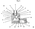
- FIG. 3 a further embodiment of a frame assembly 10 according to the invention is shown, wherein this frame assembly 10 of a plastic profile 1, which is designed as a sash, and a plastic profile 21, which is designed as a frame, is constructed.
- the casement comprises a plastic profile frame 13, in which a double-glazing with two glass panes 11, 12 connected to each other via a connecting element 14 is used as a surface supporting element 9, wherein the plastic profile frame 13 rotates the insulating glass frontally.
- the plastic profile frame 13 is composed of a main profile 15, which is composed of the plastic profile 1 according to the invention, and an additional profile 16, wherein the additional profile 16 elastic sealing lips 17, 18 are coextruded, whose free ends on the wall facing the end face of the glass pane 12 abut.
- the main profile 15 of the plastic profile frame 13 in turn has an external flashover 3 with hollow chambers 2 and a receiving portion 4, wherein on the receiving portion 4 facing side of the outer flashover 3, a groove 5 is arranged, in which the sealing element 6 is introduced.
- the sealing element 6 is introduced by rolling into the groove 5 subsequently, wherein the foot of the sealing element 6 is pressed into the undercut groove 5 and this engages behind frictionally.
- the sealing element 6 is made of a non-melt processable material.
- the sealing element 6 could also be formed from a thermoplastic elastomeric material and coextruded cohesively into the groove 5.
- the Dichtungsingnut 5 is again chamfered, wherein the plane formed by the open side of the groove 5 is angled at an angle of approximately 10 ° to a normal to the bottom 7 of the plastic profile 1.
- a holding element 8 is arranged in the casement profile, which is integrally formed on the outer flashover 3 and protrudes in the direction of the receiving portion 4.
- the holding element 8 of the plastic profile 1 is made of a harder material than a retracted into the groove 5 sealing element 6, which in turn is made of known soft elastic materials, and supports the sealing member 6 partially from.
- a further window profile 21 which is designed as a frame.
- the window profile 21 has an external flashover 23 with hollow chambers 22 and a receiving portion 24, wherein on the receiving portion 24 facing side of the outer flashover 23, a groove 25 is arranged, in which the sealing element 26 is retracted.
- the sealing element 26 is subsequently introduced by rolling into the undercut groove 25, wherein the foot of the sealing member 26, the groove 25 engages behind frictionally.
- the sealing element 26 is made of a non-thermoplastically processable material.
- the Dichtungsingnut 25 is arranged chamfered, wherein the plane formed by the open side of the groove 25 is in turn bevelled at an angle of approximately 12 ° to a normal to the bottom 27 of the plastic profile 21.
- a holding element 28 is arranged in the sash profile.
- the holding element 28 is integrally formed on the outer flashover 23, wherein it points in the direction of the receiving portion 24.
- the holding element 28 of the plastic profile 21 is made of a harder material than the retracted into the groove 25 sealing element 26 made of soft elastic material.
- the holding elements 8, 28 were used to fix and support the sealing elements 6, 26 in such a way that the sealing elements 6, 26 produced from a non-thermoplastically processable material are both supported and sealingly pressed against one another by the welded holding elements 8, 28. This ensures that the sealing element 6 in the sash and the sealing element 26 is pressed in the window frame profile sealing against the opposite sealing element, so that an optimal tightness is achieved.
- the sealing member 26 may be formed of a thermoplastic elastomeric material. This sealing element 26 can then-also-by coextrusion cohesively be introduced into the entprechende groove 25.
- a sealing member 26 made of a thermoplastic elastomeric material when welded without the use of seal depressors, the sealing member 26 extruded into the groove 25 in the resulting frame assembly is welded over its entire cross section to the opposing seal member, with the softness and elasticity of the seal members in the corner portions the frame assembly were not affected by the welding, resulting in a very high tightness.
- FIG. 3 illustrated embodiment of the present invention supports the respective holding element 8, 28 the respective sealing element 6, 26 over the entire length of the window profile 1, 21 and leads in the corner regions of the mitred and welded together window profiles 1, 21 to the sealing elements. 6 , 26 are not moved from their position during the process of fishing, pressing or welding.
- the mitered end faces of the window profiles 1, 21 due to the tapered arrangement of the Dichtungsfactnuten 5, 25 in the corner regions of the window profiles 1, 21 during welding without the use of seal depressors hardly welding consumable material pressed to the visible surfaces.
- the holding elements 8, 28 are optimally in operative connection with the respective sealing element 6, 26.
- through-the-material connection of the holding elements 8, 28 of the window profiles 1, 21, the corner strength of the resulting frame assembly 10 is increased.
Landscapes
- Engineering & Computer Science (AREA)
- Civil Engineering (AREA)
- Structural Engineering (AREA)
- Wing Frames And Configurations (AREA)
- Joining Of Corner Units Of Frames Or Wings (AREA)
Description
- Die vorliegende Erfindung betrifft eine Rahmenbaugruppe für ein Fenster und/oder eine Tür, die mindestens ein Kunststoffprofil, das einen Außenüberschlag mit wenigstens einer Hohlkammer, einen Aufnahmeabschnitt und eine am Außenüberschlag angeordnete Nut zur Aufnahme eines Dichtungselements und ein in die Nut eingezogenes Dichtungselement umfasst, wobei eine durch die offene Seite der Nut des Kunststoffprofils gebildete Ebene gegen eine Normale zur Unterseite des Kunststoffprofils abgeschrägt ist.
- Eine Vielzahl derartiger Kunststoffprofile und Rahmenbaugruppen für Türen und Fenster sind im Stand der Technik beschrieben. Beispielsweise beschreibt die
DE 40 22 827 A1 eine Rahmenbaugruppe mit einem Kunststoffprofil, wobei die Dichtungsaufnahmenut am Außenüberschlag abgeschrägt ausgebildet ist. Eine Rahmenbaugruppe mit schräg gestellter, an den Außenüberschlag anextrudierter Dichtung ist aus derGB 2 451 893 A - Generell weisen Kunststoffprofile für Türen und Fenster einen Außenüberschlag auf, an dem sich ein Dichtungselement befindet. Nach dem Verschweißen der Kunststoffprofile zu Rahmenbaugruppen für Türen oder Fenster umrahmt ein derartiges Dichtungselement ein in den Rahmen eingesetztes Flächentragelement, wobei das Dichtungselement zur Abdichtung des Flächentragelements gegenüber dem Kunststoffprofil dient.
- Beim Zusammenbau von Kunststoffprofilen zu Rahmenbaugruppen für den Fenster-, Türen- und Fassadenbau werden die auf Länge abgeteilten und an ihren Stirnseiten auf Gehrung geschnittenen Kunststoffprofile an ihren Gehrungsstößen zunächst mit einem Schweißspiegel plastifiziert. In Abhängigkeit von Wandstärke und Raumform der Kunststoffprofile ist dafür ein bestimmter Zeitraum bei erhöhter Temperatur (beispielsweise im Bereich von 250-270°C) erforderlich. Nach dem Plastifizieren wird der Schweißspiegel von den einander gegenüberliegenden Stirnseiten der Kunststoffprofile entfernt und daraufhin werden die plastifizierten Stirnseiten der Kunststoffprofile unter definiertem Druck für eine bestimmte Zeit gegeneinander gepresst, wodurch die Kunststoffprofile an ihren Gehrungsstößen miteinander verschweißt werden. Dabei entstehen an den Gehrungsstößen sog. Schweißwülste (oder Schweißabbrand), die an die Oberfläche der Rahmenbaugruppe gedrückt werden und von dort beispielsweise durch Putzen, Fräsen, Schälen oder Schneiden entfernt werden müssen und zwar insbesondere von Stellen, an denen dieses Entfernen aus Gründen der Optik und/oder zur exakten Lagefixierung von Dichtungselementen notwendig ist. Auf diese Weise können beispielsweise anschließend Dichtungselemente über ihre Verankerungsfüße über die Gehrungsstöße hinweg kontinuierlich in die jeweiligen Aufnahmenuten der Tür- und/oder Fensterprofile eingebettet werden.
- Für dieses Verfahren sind zur Herstellung von Rahmenbaugruppen bislang überwiegend Dichtungselemente aus thermoplastischen, elastomeren Werkstoffen eingesetzt worden. Dabei hat sich gezeigt, dass die Schweißwülste, die zwangsläufig im Bereich der Aufnahmenuten durch Zusammenpressen der plastifizierten Stirnseiten der Kunststoffprofile entstehen, einen scharfen, messerartigen Charakter aufweisen und somit die Dichtungselemente an den Gehrungsstößen beschädigen oder gar vollständig durchtrennen können. Dies kann Undichtigkeiten der entsprechenden Rahmenbaugruppen mit weiteren daraus resultierenden Nachteilen zur Folge haben. Darüber hinaus können derartige Schweißwülste dazu führen, dass sich das Dichtungselement im Bereich der Gehrung vom Kunststoffprofil abhebt, was Fehlfunktionen und harte Gehrungsecken der Dichtungselemente bedingen kann.
- Eine Weiterführung dieses Verfahrens ist aus der
EP 0 838 324 A2 bekannt. Durch das darin beschriebene Verfahren zum Zusammenfügen von Kunststoffprofilen zu Rahmenbaugruppen soll gewährleistet werden, dass die elastische Funktion der zu verschweißenden Dichtungen im Bereich der Gehrungsabschnitte auch nach dem Verschweißen erhalten bleibt. Zu diesem Zweck sieht das in derEP 0 838 324 A2 beschriebene Verfahren vor, während des Verschweißens der auf Gehrung geschnittenen Rahmenprofile aus Kunststoff mit den eingezogenen Dichtungen die von Dichtlippe und Befestigungsfuß der Dichtung gebildete Innenkontur der Dichtung in der Gehrungsebene und dazu benachbart durch mindestens ein Formteil, das als Schweißzulage bezeichnet wird, konturgerecht oder nahezu konturgerecht abzudecken und die Schweißzulage nach dem Verschweißen aus dem Dichtungsbereich zu entfernen. Das Abdecken der Innenkontur der Dichtungselemente im Bereich der Gehrung mittels der Schweißzulage soll verhindern, dass sich beim Verschweißen der Rahmenprofile aus Kunststoff speziell im Innenbereich der Dichtung eine Schweißraupe ausbilden kann, die sich auf die Elastizität des Dichtungselements insbesondere im Gehrungsbereich negativ auswirken kann. - Dieses Verfahren besitzt jedoch den Nachteil, dass beim Verschweißen der Kunststoffprofile zu Rahmenbaugruppen die im Kunststoffprofil eingezogenen Dichtungselemente durch weitere Bauteile wie Dichtungsniederhalter, Schneidzulagen oder Schneidniederhalter während der einzelnen Bearbeitungsschritte gehalten werden müssen, was das Verfahren verkompliziert und die für das Verfahren erforderlichen Anlagen und damit auch die durch das Verfahren hergestellten Rahmenbaugruppen verteuert. Insbesondere müssen für jede Raumform des Dichtungselements bzw. der Rahmenbaugruppe spezielle derartige Dichtungsniederhalter, Schneidzulagen oder Schneidniederhalter hergestellt, auf Lager gehalten und für die jeweiligen Arbeitsgänge montiert und demontiert werden. Dadurch treten bei der Herstellung der Rahmenbaugruppen zusätzlich Fehlerquellen auf, so dass die Herstellung der Rahmenbaugruppen weiter verteuert wird.
- Ein weiterer Nachteil des in der
EP 0 838 324 A2 beschriebenen Verfahrens besteht darin, dass in diesem Verfahren nur Dichtungselemente aus thermoplastischen, also schweißbaren Materialien eingesetzt werden können, um eine vollständige Dichtheit insbesondere im Gehrungsbereich der Rahmenbaugruppen zu gewährleisten. Nur die Verwendung derartiger schweißbarer Materialien in Verbindung mit den zusätzlichen Elementen wie Dichtungsniederhaltern, Schneidzulagen oder Schneidniederhaltem ermöglicht ein festes konturgerechtes Verschweißen der Dichtungselemente im Gehrungsbereich, wofür wiederum für jedes Dichtungselement spezifische Schweißzulagen erforderlich werden. - Gemäß der
DE 20 2006 002 741 U1 kann die Verwendung von Elementen wie Niederhaltern beim Verschweißen von Tür- und/oder Fensterprofilen dadurch vermieden werden, dass das Tür- und/oder Fensterprofil einen Außenüberschlag mit einer darin angeordneten Nut zur Aufnahme eines Dichtungselements aufweist, wobei die Nut etwa orthogonal zu einem Falzgrund des Tür- und/oder Fensterprofils angeordnet ist und zwischen dem Falzgrund und dem Dichtungselement ein das Dichtungselement wenigstens teilweise abstützendes Halteelement angeordnet ist - Die Anordnung eines derartigen Halteelements zwischen dem Falzgrund und dem Dichtungselement sowie die etwa orthogonale Anordnung der Nut zum Falzgrund stellen aber Einschränkungen bei der Wahl der Profilgeometrie dar.
- Somit liegt der vorliegenden Erfindung die Aufgabe zu Grunde, die Nachteile des Stands der Technik zu überwinden und eine Rahmenbaugruppe für ein Fenster und/oder eine Tür mit einem Kunststoffprofil zur Verfügung zu stellen, das ein wirtschaftliches und kostengünstiges Verschweißen der Kunststoffprofile zu einer Rahmenbaugruppe ermöglicht, wobei die Kunststoffprofile mit den darin eingezogenen Dichtungselementen werkstoff- und geometrieunabhängig mit bekannten Schweißmaschinen verbindbar sein sollen und die im Gehrungsbereich eine den gesetzlichen Bestimmungen genügende Dichtheit aufweisen sollen. Darüber hinaus sollen die Dichtungselemente insbesondere im Gehrungsbereich auch nach dem Verschweißen bzw. Fügen elastisch bleiben.
- Erfindungsgemäß werden diese Aufgaben durch eine Rahmenbaugruppe für ein Fenster und/oder eine Tür gemäß Anspruch 1 gelöst. Bevorzugte Ausführungsformen der erfindungsgemäßen Rahmenbaugruppe sind in den jeweils davon abhängigen Ansprüchen beschrieben.
- Es wurde gemäß der vorliegenden Erfindung erkannt, dass das Auftreten von Schweißwülsten an der außen sichtbaren Oberfläche der Kunststoffprofile beim Verschweißen von auf Gehrung geschnittenen Kunststoffprofilen im Bereich der Dichtungselemente überraschenderweise stark vermindert werden kann, indem die Nut zur Aufnahme des Dichtungselements abgeschrägt angeordnet ist.
- Damit stellt die vorliegende Erfindung eine Rahmenbaugruppe für ein Fenster und/oder eine Tür zur Verfügung, die mindestens ein Kunststoffprofil mit einem Außenüberschlag mit wenigstens einer Hohlkammer, einem Aufnahmeabschnitt und einer am Außenüberschlag angeordneten Nut zur Aufnahme eines Dichtelements und einem in die Nut eingezogenen Dichtelement umfasst, wobei eine durch die offene Seite der Nut gebildete Ebene um einen Winkel im Bereich von 8° bis 12° gegen eine Normale zur Unterseite des Kunststoffprofils abgeschrägt ist.
- Auf diese Weise ist gewährleistet, dass in der resultierenden Rahmenbaugruppe das Dichtungselement im Gehrungsbereich konturgerecht verschweißt ist und nach dem Verschweißen weich und elastisch bleibt. Durch diese erfindungsgemäß abgeschrägte Anordnung der Dichtungsaufnahmenut sind beim Verschweißen der Kunststoffprofile zu Rahmenbaugruppen für Türen und/oder Fenster keine zusätzlichen Sonderbauteile in den Schweißmaschinen bzw. in den Schneidmaschinen erforderlich. Die Rüstkosten derartiger Maschinen sowie die Lagerhaltung und Bevorratung zusätzlicher Elemente wie Dichtungsniederhalter, Schneidzulagen, Schneidniederhalter bzw. Schweißzulagen sind nicht mehr erforderlich. Das erfindungsgemäße Kunststoffprofil hat den weiteren Vorteil, dass es für die daraus resultierenden Rahmenbaugruppen die Verwendung von Dichtungselementen sowohl aus schweißbarem, als auch aus nicht schweißbarem Material ermöglicht. Bei Dichtungselementen aus nicht schweißbaren Materialien ist gewährleistet, dass sich diese aufgrund der verringerten Bildung von Schweißbrandwülsten an der sichtbaren Oberfläche der Kunststoffprofile im Gehrungsbereich nicht vom Profil abheben und durch den Fügevorgang eine entsprechende Dichtheit im Gehrungsbereich erzeugt werden kann.
- Das Kunststoffprofil erlaubt damit überraschenderweise eine kostengünstige, geometrie- und materialunabhängige Herstellung von Rahmenbaugruppen für Fenster und/oder Türen, die im Gehrungsbereich über die erforderliche Dichtheit verfügen.
- Erfindungsgemäß ist die durch die offene Seite der Nut gebildete Ebene um einen Winkel im Bereich von 8° bis 12° und bevorzugt um etwa 10° gegen eine Normale zur Unterseite des Kunststoffprofils abgeschrägt. Liegt der Winkel, um den die Nut gegen die Normale zur Unterseite des Profils abschrägt ist, innerhalb des genannten Bereichs, wird ein Auftreten von Schweißabbrand an der Außenoberfläche des Kunststoffprofils in ausreichender Weise verhindert, so dass beim Verschweißen der auf Gehrung geschnittenen Kunststoffprofile auf die Verwendung zusätzlicher Elemente wie Dichtungsniederhalter, Schneidzulagen, Schneidniederhalter bzw. Schweißzulagen verzichtet werden kann, wobei durch die Abschrägung der Nut die optische Ausgestaltung der das Kunststoffprofil enthaltenden erfindungsgemäßen Rahmenbaugruppe nicht übermäßig nachteilig beeinflusst wird.
- Darüber hinaus kann es nützlich sein, wenn unterhalb der Nut ein Halteelement vorgesehen ist. Durch eine derartige Anordnung des Halteelementes unterhalb der Nut kann ein in die Nut eingezogenes Dichtungselement teilweise abgestützt werden. Auf diese Weise kann das Dichtungselement während des Verschweißens der auf Gehrung geschnittenen Kunststoffprofile zu erfindungsgemäßen Rahmenbaugruppen gestützt bzw. gehalten werden, so dass ein konturgerechtes Verschweißen des Dichtungselements im Gehrungsbereich weiter gefördert wird. Ferner erhöht ein stoffschlüssiges Verbinden der Halteelemente der Fensterprofile durch das Verschweißen die Eckfestigkeit der resultierenden Rahmenbaugruppe zusätzlich. Es kann in diesem Zusammenhang in Bezug auf die erfindungsgemäße Rahmenbaugruppe daher auch von Vorteil sein, wenn das Halteelement das Dichtungselement zumindest teilweise abstützt. Dabei kann es sich als besonders günstig erweisen, wenn das Halteelement an dem in die Nut eingezogenen Dichtungselement anliegt.
- Es kann ferner günstig sein, wenn dieses Halteelement aus einem härten Werkstoff als das in die Nut eingezogene Dichtungselement aufgebaut ist. Dadurch kann gewährleistet werden, dass das Halteelement selbst im Gehrungsbereich verschweißt ist und somit das Dichtungselement in diesem kritischen Bereich beim Verschweißen zusätzlich führt bzw. abstützt.
- Im Folgenden soll die vorliegende Erfindung anhand der in den Figuren dargestellten, nicht einschränkenden Ausführungsbeispiele näher beschrieben werden.
- In den Figuren zeigt
- Fig. 1
- eine Querschnittsdarstellung eines Kunststoffprofils zur Verwendung in einer erfindungsgemäßen Rahmenbaugruppe,
- Fig. 2
- einen Schnitt durch eine partiell dargestellte erfindungsgemäße Rahmenbaugruppe, in die ein Flächentragelement in Form einer Isolierverglasung eingesetzt ist, und
- Fig. 3
- einen Schnitt durch eine weitere partiell dargestellte erfindungsgemäße Rahmenbaugruppe aus Flügel- und Blendrahmen, wobei in den Flügelrahmen ein Flächentragelement in Form einer Isolierverglasung eingesetzt ist.
- In
Fig. 1 ist eine Ausführungsform des Kunststoffprofils 1 dargestellt. Es ist als Fensterprofil ausgestaltet und weist einen Außenüberschlag 3 mit mehreren Hohlkammern 2 und einen Aufnahmeabschnitt 4 auf. An der dem Aufnahmeabschnitt 4 zugewandten Seite des Außenüberschlags 3 ist eine Nut 5 zur Aufnahme eines Dichtungselements (inFig. 1 nicht dargestellt) angeordnet. In an sich bekannter Weise ist das Kunststoffprofil 1 aus Hohlkammern 2 sowie diese umgebende Stege aus einem thermoplastisch verarbeitbaren Werkstoff wie beispielsweise PVC aufgebaut und durch Extrusion hergestellt. - Die durch die offene Seite der Nut 5 gebildete Ebene ist um einen Winkel von etwa 10° gegen eine Normale zu einer Unterseite 7 des Kunststoffprofils 1 abgeschrägt. In diese Nut 5 ist ein Dichtungselement, insbesondere ein Dichtungsprofil eingezogen. Das Einziehen des Dichtungselements kann entweder nachträglich, wobei das Dichtungselement beispielsweise durch Einrollen eingebracht werden kann, indem ein Fuß des Dichtungselementes in die hinterschnittig ausgebildete Nut 5 eingepresst wird und diese kraftschlüssig hintergreift, oder bei der Herstellung des Kunststoffprofils mittels Coextrusion erfolgen. In letzterem Fall ist das Dichtungselement stoffschlüssig mit der Nut 5 verbunden.
- Unterhalb der Nut 5 ist in diesem Ausführungsbeispiel ein Halteelement 8 angeordnet, das an den Außenüberschlag 3 einstückig angeformt ist und in Richtung des Aufnahmeabschnitts 4 ragt. Das Halteelement 8 des Kunststoffprofils 1 ist vorzugsweise aus einem härteren Werkstoff als das in die Nut 5 einzuziehende Dichtungselement 6 hergestellt, das aus bekannten weichelastischen Materialien hergestellt ist.
- Beim Verschweißen der an den Stirnseiten auf Gehrung zugesägten Kunststoffprofile 1 zu einer erfindungsgemäßen Rahmenbaugruppe ohne Verwendung von Dichtungsniederhaltern tritt durch die abgeschrägte Anordnung der Dichtungsaufnahmenut 5 im Gehrungsbereich kaum Schweißabbrandmaterial an der sichtbaren Oberfläche des Kunststoffprofils 1 auf, so dass das in die Nut 5 eingezogene Dichtungselement aus einem thermoplastischen Material über seinen gesamten Querschnitt mit dem gegenüberliegenden Dichtungselement verschweißt ist und somit zu einer optimalen Dichtheit der resultierenden Rahmenbaugruppe führt. Auch nach dem Verschweißen bleiben die Dichtungselemente im kritischen Gehrungsbereich weich und elastisch.
- Das Dichtungselement kann in einer alternativen Ausführungsform auch aus einem nicht thermoplastisch verarbeitbaren Material hergestellt sein. In diesem Fall ist durch die Abschrägung der Dichtungsaufnahmenut 5 gewährleistet, dass das Dichtungselement in der resultierenden Rahmenbaugruppe dichtend gegen das gegenüberliegende Dichtungselement gepresst wird.
- In
Fig. 2 ist ein Ausführungsbeispiel einer erfindungsgemäßen Rahmenbaugruppe 10 dargestellt. Die Rahmenbaugruppe 10 umfasst einen Kunststoffprofilrahmen 13, der ein Flächentragelement 9 in dessen Stirnseitenbereichen umgibt. In diesem Ausführungsbeispiel ist das Flächentragelement 9 eine Isolierverglasung mit zwei miteinander über ein Verbindungselement 14 verbundenen Glasscheiben 11, 12. - Der Kunststoffprofilrahmen 13 ist aus einem Hauptprofil 15, der aus dem Kunststoffprofil 1 aufgebaut ist, und einem Zusatzprofil 16 zusammengesetzt, wobei an das Zusatzprofil 16 elastische Dichtlippen 17, 18 anextrudiert sind. Die freien Enden der Dichtlippen 17, 18 liegen an der ihnen zugewandten Wand des Stirnseitenbereichs der Glasscheibe 12 an.
- Das Hauptprofil 15 des Kunststoffprofilrahmens 13 weist einen Außenüberschlag 3 mit Hohlkammern 2 und einen Aufnahmeabschnitt 4 auf. An der dem Aufnahmeabschnitt 4 zugewandten Seite des Außenüberschlags 3 ist eine Nut 5 angeordnet, in die das Dichtungselement 6 eingebracht ist, das in dieser Ausführungsform als durch Coextrusion eingebrachtes Dichtungselement 6 aus einem thermoplastischen Material ausgebildet ist. Alternativ dazu kann das Dichtungselement 6 auch aus einem nicht thermoplastisch verarbeitbaren Material hergestellt sein. In diesem Fall wird das Dichtungselement 6 nachträglich in die Dichtungsaufnahmenut 5 eingezogen.
- Die durch die offene Seite der Nut 5 gebildete Ebene ist um einen Winkel von ungefähr 10° gegen eine Normale zur Unterseite 7 des Kunststoffprofils 1 abgeschrägt.
- Durch die abgeschrägte Anordnung der Dichtungsaufnahmenut 5 im Hauptprofil 15 des Kunststoff-Profilrahmens 13 wurde in den Eckbereichen der erfindungsgemäßen Rahmenbaugruppe 10 beim Verschweißen ohne Verwendung von Dichtungsniederhaltern kaum Schweißabbrandmaterial an die sichtbaren Oberflächen gedrückt. Dadurch ist das in die Nut 5 einextrudierte Dichtungselement 6 in der erfindungsgemäßen Rahmenbaugruppe 10 über seinen gesamten Querschnitt mit dem gegenüberliegenden Dichtungselement verschweißt, wobei die Weichheit und Elastizität der Dichtungselemente in den Eckbereichen der Rahmenbaugruppe durch das Verschweißen nicht beeinträchtig wurden, so dass eine optimale Dichtheit gewährleistet ist. Für den Fall eines Dichtungselements 6 aus einem nicht thermoplastisch verarbeitbaren Material ist durch die Abschrägung der Dichtungsaufnahmenut 5 gewährleistet, dass das Dichtungselement 6 in der resultierenden Rahmenbaugruppe 10 dichtend gegen das gegenüberliegende Dichtungselement 6 gepresst wird.
- In
Fig. 3 ist eine weitere Ausführungsform einer erfindungsgemäßen Rahmenbaugruppe 10 dargestellt, wobei diese Rahmenbaugruppe 10 aus einem Kunststoffprofil 1, das als Flügelrahmen ausgebildet ist, und einem Kunststoffprofil 21, welches als Blendrahmen ausgebildet ist, aufgebaut ist. - Der Flügelrahmen umfasst einen Kunststoffprofilrahmen 13, in den eine Isolierverglasung mit zwei miteinander über ein Verbindungselement 14 verbundenen Glasscheiben 11, 12 als Flächentragelement 9 eingesetzt ist, wobei der Kunststoffprofilrahmen 13 die Isolierverglasung stirnseitig umläuft. Der Kunststoffprofilrahmen 13 setzt sich aus einem Hauptprofil 15, der aus dem erfindungsgemäßen Kunststoffprofil 1 aufgebaut ist, und einem Zusatzprofil 16 zusammen, wobei an das Zusatzprofil 16 elastische Dichtlippen 17, 18 coextrudiert sind, deren freie Enden an der ihnen zugewandten Wand des Stirnseitenbereichs der Glasscheibe 12 anliegen.
- Das Hauptprofil 15 des Kunststoffprofilrahmens 13 besitzt wiederum einen Außenüberschlag 3 mit Hohlkammern 2 und einen Aufnahmeabschnitt 4, wobei an der dem Aufnahmeabschnitt 4 zugewandten Seite des Außenüberschlags 3 eine Nut 5 angeordnet ist, in die das Dichtungselement 6 eingebracht ist. In dieser Ausführungsform der vorliegenden Erfindung ist das Dichtungselement 6 durch Einrollen in die Nut 5 nachträglich eingebracht, wobei der Fuß des Dichtungselementes 6 in die hinterschnittig ausgebildete Nut 5 eingepresst ist und diese kraftschlüssig hintergreift. Das Dichtungselement 6 ist dabei aus einem nicht thermoplastisch verarbeitbaren Material hergestellt. Alternativ dazu könnte das Dichtungselement 6 auch aus einem thermoplastischen, elastomeren Material ausgebildet und durch Coextrusion stoffschlüssig in die Nut 5 eingebracht worden sein.
In dem Flügelrahmenprofil ist die Dichtungsaufnahmenut 5 wiederum abgeschrägt angeordnet, wobei die durch die offene Seite der Nut 5 gebildete Ebene um einen Winkel von ungefähr 10° gegen eine Normale zur Unterseite 7 des Kunststoffprofils 1 abgeschrägt ist. - Unterhalb der Nut 5 ist in dem Flügelrahmenprofil ein Halteelement 8 angeordnet, das an den Außenüberschlag 3 einstückig angeformt ist und in Richtung des Aufnahmeabschnitts 4 ragt. Das Halteelement 8 des Kunststoffprofils 1 ist aus einem härteren Werkstoff als ein in die Nut 5 eingezogenes Dichtungselement 6 hergestellt, das wiederum aus bekannten weichelastischen Materialien hergestellt ist, und stützt das Dichtungselement 6 teilweise ab.
- Am Fensterprofil 1, das als Flügelrahmen ausgebildet ist, liegt über ein weiteres Dichtungselement 26 ein weiteres Fensterprofil 21 an, das als Blendrahmen ausgebildet ist. Auch das Fensterprofil 21 weist einen Außenüberschlag 23 mit Hohlkammern 22 und einen Aufnahmeabschnitt 24 auf, wobei an der dem Aufnahmeabschnitt 24 zugewandten Seite des Außenüberschlags 23 eine Nut 25 angeordnet ist, in die das Dichtungselement 26 eingezogen ist. Auch in dem als Blendrahmen ausgeführten Kunststoffprofil 21 ist das Dichtungselement 26 nachträglich durch Einrollen in die hinterschnittig ausgebildete Nut 25 eingebracht, wobei der Fuß des Dichtungselements 26 die Nut 25 kraftschlüssig hintergreift. Dabei ist das Dichtungselement 26 aus einem nicht thermoplastisch verarbeitbaren Material hergestellt.
- In dem Blendrahmenprofil ist die Dichtungsaufnahmenut 25 abgeschrägt angeordnet, wobei die durch die offene Seite der Nut 25 gebildete Ebene wiederum um einen Winkel von ungefähr 12° gegen eine Normale zur Unterseite 27 des Kunststoffprofils 21 abgeschrägt ist. Unterhalb der Nut 25 ist in dem Flügelrahmenprofil ein Halteelement 28 angeordnet. Das Halteelement 28 ist einstückig an den Außenüberschlag 23 angeformt ist, wobei es in Richtung des Aufnahmeabschnitts 24 weist. Das Halteelement 28 des Kunststoffprofils 21 ist aus einem härteren Werkstoff als das in die Nut 25 eingezogene Dichtungselement 26 aus weichelastischem Material hergestellt.
- Beim Verschweißen der auf Gehrung geschnittenen Stirnseiten der Fensterprofile 1, 21 wurde aufgrund der abgeschrägten Anordnung der Dichtungsaufnahmenuten 5, 25 in den Eckbereichen der erfindungsgemäßen Rahmenbaugruppe 10 beim Verschweißen ohne Verwendung von Dichtungsniederhaltern kaum Schweißabbrandmaterial an die sichtbaren Oberflächen gedrückt. Zusätzlich erfolgte durch die Halteelemente 8, 28 ein Fixieren und Abstützen der Dichtungselemente 6, 26 derart, dass die aus einem nicht thermoplastisch verarbeitbaren Material hergestellten Dichtungselemente 6, 26 durch die verschweißten Halteelemente 8, 28 sowohl abgestützt als auch dichtend aneinander gepresst ausgebildet sind. Dadurch ist gewährleistet, dass das Dichtungselement 6 in dem Flügelrahmen und das Dichtungselement 26 in dem Blendrahmenprofil dichtend gegen das gegenüberliegende Dichtungselement gepresst wird, so dass eine optimale Dichtheit erzielt wird.
- In einer weiteren Ausführungsform der vorliegenden Erfindung kann das Dichtungselemente 26 aus einem thermoplastischen, elastomeren Material ausgebildet sein. Dieses Dichtungselement 26 kann dann-auch-durch Coextrusion stoffschlüssig in die entprechende Nut 25 eingebracht worden sein. Im Fall eines Dichtungselemente 26 aus einem thermoplastischen, elastomeren Material wird beim Verschweißen ohne Verwendung von Dichtungsniederhaltern das in die Nut 25 einextrudierte Dichtungselement 26 in der resultierenden Rahmenbaugruppe über seinen gesamten Querschnitt mit dem gegenüberliegenden Dichtungselement verschweißt, wobei die Weichheit und Elastizität der Dichtungselemente in den Eckbereichen der Rahmenbaugruppe durch das Verschweißen nicht beeinträchtig wurden, woraus sich eine sehr hohe Dichtheit ergibt.
- In der in
Fig. 3 dargestellten Ausführungsform der vorliegenden Erfindung stützt das betreffenden Halteelement 8, 28 das jeweilige Dichtungselement 6, 26 über die gesamte Länge des Fensterprofils 1, 21 ab und führt in den Eckbereichen der auf Gehrung geschnittenen und miteinander verschweißten Fensterprofile 1, 21 dazu, dass die Dichtungselemente 6, 26 beim Vorgang des Angelierens, Verpressens bzw. Verschweißens nicht aus ihrer Position bewegt werden. Darüber hinaus wird beim Verschweißen der auf Gehrung geschnittenen Stirnseiten der Fensterprofile 1, 21 aufgrund der abgeschrägten Anordnung der Dichtungsaufnahmenuten 5, 25 in den Eckbereichen der Fensterprofile 1, 21 beim Verschweißen ohne Verwendung von Dichtungsniederhaltern kaum Schweißabbrandmaterial an die sichtbaren Oberflächen gedrückt. Somit stehen beim Verschweißen der auf Gehrung geschnittenen Stirnseiten der Fensterprofile 1, 21, die Halteelemente 8, 28 optimal mit dem jeweiligen Dichtungselement 6, 26-in Wirkverbindung. Zusätzlich wird durch-das-stoffschlüssige Verbinden der Halteelemente 8, 28 der Fensterprofils 1, 21 die Eckfestigkeit der resultierenden Rahmenbaugruppe 10 erhöht.
Claims (5)
- Rahmenbaugruppe (10) für ein Fenster und/oder eine Tür, umfassend- mindestens ein Kunststoffprofil (1, 21), umfassend einen Außenüberschlag (3, 23) mit wenigstens einer Hohlkammer (2, 22), einen Aufnahmeabschnitt (4, 24) und eine am Außenüberschlag (3, 23) angeordnete Nut (5, 25) zur Aufnahme eines Dichtelements (6, 26), und- ein in die Nut (5, 25) des Kunststoffprofils (1, 21) eingezogenes Dichtelement (6, 26),wobei eine durch die offene Seite der Nut (5, 25) des Kunststoffprofils (1, 21) gebildete Ebene gegen eine Normale zur Unterseite (7, 27) des Kunststoffprofils (1, 21) abgeschrägt ist,
dadurch gekennzeichnet, dass
die durch die offene Seite der Nut (5, 25) gebildete Ebene um einen Winkel im Bereich von 8° bis 12° gegen eine Normale zur Unterseite (7, 27) des Kunststoffprofils (1, 21) abgeschrägt ist. - Rahmenbaugruppe (10) für ein Fenster und/oder eine Tür gemäß Anspruch 1, dadurch gekennzeichnet, dass die Rahmenbaugruppe (10) ferner ein mindestens eine Glasscheibe (11, 12) umfassendes Flächentragelement (9) umfasst, wobei ein KunststoffProfilrahmen (13) aus dem Kunststoffprofil (1) das Flächentragelement (9) stirnseitig umläuft.
- Rahmenbaugruppe (10) für ein Fenster und/oder eine Tür gemäß Anspruch 1 oder Anspruch 2, dadurch gekennzeichnet, dass das Kunststoffprofil (1, 21) weiterhin ein Halteelement (8, 28) umfasst, das das Dichtelement (7, 27) zumindest teilweise abstützt.
- Rahmenbaugruppe (10) für ein Fenster und/oder eine Tür gemäß Anspruch 3, dadurch gekennzeichnet, dass das Halteelement (8, 28) an dem Dichtungselement (7, 27) anliegt.
- Rahmenbaugruppe (10) für ein Fenster und/oder eine Tür gemäß Anspruch 3 oder Anspruch 4, dadurch gekennzeichnet, dass das Halteelement (8, 28) aus einem härteren Werkstoff als das Dichtungselement (7, 27) aufgebaut ist.
Priority Applications (2)
| Application Number | Priority Date | Filing Date | Title |
|---|---|---|---|
| DK09008948.3T DK2284349T3 (da) | 2009-07-09 | 2009-07-09 | Rammekomponent til et vindue eller en dør. |
| EP09008948.3A EP2284349B1 (de) | 2009-07-09 | 2009-07-09 | Rahmenbaugruppe für ein Fenster oder eine Tür |
Applications Claiming Priority (1)
| Application Number | Priority Date | Filing Date | Title |
|---|---|---|---|
| EP09008948.3A EP2284349B1 (de) | 2009-07-09 | 2009-07-09 | Rahmenbaugruppe für ein Fenster oder eine Tür |
Publications (2)
| Publication Number | Publication Date |
|---|---|
| EP2284349A1 EP2284349A1 (de) | 2011-02-16 |
| EP2284349B1 true EP2284349B1 (de) | 2016-09-07 |
Family
ID=41361256
Family Applications (1)
| Application Number | Title | Priority Date | Filing Date |
|---|---|---|---|
| EP09008948.3A Active EP2284349B1 (de) | 2009-07-09 | 2009-07-09 | Rahmenbaugruppe für ein Fenster oder eine Tür |
Country Status (2)
| Country | Link |
|---|---|
| EP (1) | EP2284349B1 (de) |
| DK (1) | DK2284349T3 (de) |
Family Cites Families (4)
| Publication number | Priority date | Publication date | Assignee | Title |
|---|---|---|---|---|
| FR2650330B1 (fr) * | 1989-07-26 | 1993-12-17 | Soprofen Sarl | Dispositif de fermeture, au moins a double frappe, notamment pour fenetres, portes-fenetres et portes |
| DE19644183A1 (de) | 1996-10-24 | 1998-04-30 | Schueco Int Kg | Verfahren und Vorrichtung zum Verschweißen von auf Gehrung geschnittenen Rahmenprofilen aus Kunststoff mit eingezogenen Dichtungen |
| DE202006002741U1 (de) | 2006-02-21 | 2007-06-28 | Rehau Ag + Co. | Rahmenbaugruppe |
| GB2451893B (en) * | 2007-08-17 | 2012-11-14 | Eurocell Profiles Ltd | Frame members |
-
2009
- 2009-07-09 EP EP09008948.3A patent/EP2284349B1/de active Active
- 2009-07-09 DK DK09008948.3T patent/DK2284349T3/da active
Also Published As
| Publication number | Publication date |
|---|---|
| DK2284349T3 (da) | 2017-01-02 |
| EP2284349A1 (de) | 2011-02-16 |
Similar Documents
| Publication | Publication Date | Title |
|---|---|---|
| EP3712368B1 (de) | Rahmenprofil eines blend- und/oder flügelrahmens, sowie verfahren zu dessen herstellung | |
| EP0953714A1 (de) | Verfahren zum Zusammenbau von Fenster- oder Türflügeln | |
| EP2196614A2 (de) | Dichtungsprofil, Verbindungsvorrichtung und Dichtung | |
| DE102005035279B4 (de) | Fensterprofil | |
| DE102011120374A1 (de) | Eckverbinderprofil mit schlitzförmiger Nut | |
| DE2840656A1 (de) | Rahmen fuer fenster, tueren u.dgl. | |
| EP2363567B1 (de) | Rahmen eines Kunststofffensters oder einer Kunststofftür | |
| DE202005021480U1 (de) | Verbindungselemente für Platten, insbesondere aus Glas, zur Befestigung derselben und derart ausgerüstete Platten | |
| DE4201340C1 (en) | Elastomeric sealing strip for windows - has co-extruded double layer with softer base surface and sealing lips and harder supporting shell extending across base surface and part of lips | |
| EP2055462A2 (de) | Verfahren zum Verschweißen von auf Gehrung geschnittenen Rahmenprofilen für Fenster, Türen oder dergleichen sowie Dichtungsstreifen zur Verwendung bei solchen Rahmenprofilen | |
| EP0428077B1 (de) | Verfahren zur Verbindung von Kunststoff-Fensterprofilen mit anextrudierten Dichtungen | |
| WO2005019587A1 (de) | Flugelrahmenprofil und kunststofffenster mit eingeklebter verglasung | |
| EP2284349B1 (de) | Rahmenbaugruppe für ein Fenster oder eine Tür | |
| EP1989386B1 (de) | Rahmenbaugruppe | |
| EP2236723B1 (de) | Verfahren zum Verbinden von Kunststoff-Hohlkammerprofilen im Eckbereich | |
| EP0082338B1 (de) | Verbundfenster | |
| DE19754716A1 (de) | Kunststoff-Fenster und Verfahren zu dessen Herstellung | |
| DE19612285A1 (de) | Verfahren zur Herstellung von Fensterrahmen aus Kunststoff | |
| AT393534B (de) | Dichtungs-formstueck | |
| DE19822292C2 (de) | Verfahren zur Verbindung von Profilholmen zwecks Bildung von Kunststoffrahmen und Verbindung von Profilholmen | |
| DE3219929A1 (de) | Bauprofilleiste, insbesondere zur herstellung von fensterrahmen | |
| DE10001636A1 (de) | Fenster-/Türrahmen | |
| DE4039386C2 (de) | Elastisches Strangdichtungsprofil zum Abdichten von Verglasungen in Flügeln von Holzfenstern oder Holztüren | |
| EP4191012A1 (de) | Gebäudeöffnungs-schliesselement und verfahren zu seiner herstellung | |
| DE4421804A1 (de) | Anordnung zur Abdichtung |
Legal Events
| Date | Code | Title | Description |
|---|---|---|---|
| PUAI | Public reference made under article 153(3) epc to a published international application that has entered the european phase |
Free format text: ORIGINAL CODE: 0009012 |
|
| AK | Designated contracting states |
Kind code of ref document: A1 Designated state(s): AT BE BG CH CY CZ DE DK EE ES FI FR GB GR HR HU IE IS IT LI LT LU LV MC MK MT NL NO PL PT RO SE SI SK SM TR |
|
| AX | Request for extension of the european patent |
Extension state: AL BA RS |
|
| 17P | Request for examination filed |
Effective date: 20110718 |
|
| 17Q | First examination report despatched |
Effective date: 20110817 |
|
| GRAP | Despatch of communication of intention to grant a patent |
Free format text: ORIGINAL CODE: EPIDOSNIGR1 |
|
| INTG | Intention to grant announced |
Effective date: 20160428 |
|
| GRAS | Grant fee paid |
Free format text: ORIGINAL CODE: EPIDOSNIGR3 |
|
| GRAA | (expected) grant |
Free format text: ORIGINAL CODE: 0009210 |
|
| AK | Designated contracting states |
Kind code of ref document: B1 Designated state(s): AT BE BG CH CY CZ DE DK EE ES FI FR GB GR HR HU IE IS IT LI LT LU LV MC MK MT NL NO PL PT RO SE SI SK SM TR |
|
| REG | Reference to a national code |
Ref country code: GB Ref legal event code: FG4D Free format text: NOT ENGLISH |
|
| REG | Reference to a national code |
Ref country code: CH Ref legal event code: EP |
|
| REG | Reference to a national code |
Ref country code: IE Ref legal event code: FG4D Free format text: LANGUAGE OF EP DOCUMENT: GERMAN |
|
| REG | Reference to a national code |
Ref country code: AT Ref legal event code: REF Ref document number: 827052 Country of ref document: AT Kind code of ref document: T Effective date: 20161015 |
|
| REG | Reference to a national code |
Ref country code: DE Ref legal event code: R096 Ref document number: 502009013042 Country of ref document: DE |
|
| REG | Reference to a national code |
Ref country code: DK Ref legal event code: T3 Effective date: 20161227 |
|
| REG | Reference to a national code |
Ref country code: LT Ref legal event code: MG4D |
|
| REG | Reference to a national code |
Ref country code: NL Ref legal event code: MP Effective date: 20160907 |
|
| PG25 | Lapsed in a contracting state [announced via postgrant information from national office to epo] |
Ref country code: HR Free format text: LAPSE BECAUSE OF FAILURE TO SUBMIT A TRANSLATION OF THE DESCRIPTION OR TO PAY THE FEE WITHIN THE PRESCRIBED TIME-LIMIT Effective date: 20160907 Ref country code: FI Free format text: LAPSE BECAUSE OF FAILURE TO SUBMIT A TRANSLATION OF THE DESCRIPTION OR TO PAY THE FEE WITHIN THE PRESCRIBED TIME-LIMIT Effective date: 20160907 Ref country code: NO Free format text: LAPSE BECAUSE OF FAILURE TO SUBMIT A TRANSLATION OF THE DESCRIPTION OR TO PAY THE FEE WITHIN THE PRESCRIBED TIME-LIMIT Effective date: 20161207 Ref country code: LT Free format text: LAPSE BECAUSE OF FAILURE TO SUBMIT A TRANSLATION OF THE DESCRIPTION OR TO PAY THE FEE WITHIN THE PRESCRIBED TIME-LIMIT Effective date: 20160907 |
|
| PG25 | Lapsed in a contracting state [announced via postgrant information from national office to epo] |
Ref country code: SE Free format text: LAPSE BECAUSE OF FAILURE TO SUBMIT A TRANSLATION OF THE DESCRIPTION OR TO PAY THE FEE WITHIN THE PRESCRIBED TIME-LIMIT Effective date: 20160907 Ref country code: GR Free format text: LAPSE BECAUSE OF FAILURE TO SUBMIT A TRANSLATION OF THE DESCRIPTION OR TO PAY THE FEE WITHIN THE PRESCRIBED TIME-LIMIT Effective date: 20161208 Ref country code: ES Free format text: LAPSE BECAUSE OF FAILURE TO SUBMIT A TRANSLATION OF THE DESCRIPTION OR TO PAY THE FEE WITHIN THE PRESCRIBED TIME-LIMIT Effective date: 20160907 Ref country code: NL Free format text: LAPSE BECAUSE OF FAILURE TO SUBMIT A TRANSLATION OF THE DESCRIPTION OR TO PAY THE FEE WITHIN THE PRESCRIBED TIME-LIMIT Effective date: 20160907 Ref country code: LV Free format text: LAPSE BECAUSE OF FAILURE TO SUBMIT A TRANSLATION OF THE DESCRIPTION OR TO PAY THE FEE WITHIN THE PRESCRIBED TIME-LIMIT Effective date: 20160907 |
|
| PG25 | Lapsed in a contracting state [announced via postgrant information from national office to epo] |
Ref country code: EE Free format text: LAPSE BECAUSE OF FAILURE TO SUBMIT A TRANSLATION OF THE DESCRIPTION OR TO PAY THE FEE WITHIN THE PRESCRIBED TIME-LIMIT Effective date: 20160907 Ref country code: RO Free format text: LAPSE BECAUSE OF FAILURE TO SUBMIT A TRANSLATION OF THE DESCRIPTION OR TO PAY THE FEE WITHIN THE PRESCRIBED TIME-LIMIT Effective date: 20160907 |
|
| PG25 | Lapsed in a contracting state [announced via postgrant information from national office to epo] |
Ref country code: SK Free format text: LAPSE BECAUSE OF FAILURE TO SUBMIT A TRANSLATION OF THE DESCRIPTION OR TO PAY THE FEE WITHIN THE PRESCRIBED TIME-LIMIT Effective date: 20160907 Ref country code: BG Free format text: LAPSE BECAUSE OF FAILURE TO SUBMIT A TRANSLATION OF THE DESCRIPTION OR TO PAY THE FEE WITHIN THE PRESCRIBED TIME-LIMIT Effective date: 20161207 Ref country code: SM Free format text: LAPSE BECAUSE OF FAILURE TO SUBMIT A TRANSLATION OF THE DESCRIPTION OR TO PAY THE FEE WITHIN THE PRESCRIBED TIME-LIMIT Effective date: 20160907 Ref country code: PL Free format text: LAPSE BECAUSE OF FAILURE TO SUBMIT A TRANSLATION OF THE DESCRIPTION OR TO PAY THE FEE WITHIN THE PRESCRIBED TIME-LIMIT Effective date: 20160907 Ref country code: PT Free format text: LAPSE BECAUSE OF FAILURE TO SUBMIT A TRANSLATION OF THE DESCRIPTION OR TO PAY THE FEE WITHIN THE PRESCRIBED TIME-LIMIT Effective date: 20170109 Ref country code: CZ Free format text: LAPSE BECAUSE OF FAILURE TO SUBMIT A TRANSLATION OF THE DESCRIPTION OR TO PAY THE FEE WITHIN THE PRESCRIBED TIME-LIMIT Effective date: 20160907 Ref country code: IS Free format text: LAPSE BECAUSE OF FAILURE TO SUBMIT A TRANSLATION OF THE DESCRIPTION OR TO PAY THE FEE WITHIN THE PRESCRIBED TIME-LIMIT Effective date: 20170107 |
|
| REG | Reference to a national code |
Ref country code: DE Ref legal event code: R097 Ref document number: 502009013042 Country of ref document: DE |
|
| PG25 | Lapsed in a contracting state [announced via postgrant information from national office to epo] |
Ref country code: IT Free format text: LAPSE BECAUSE OF FAILURE TO SUBMIT A TRANSLATION OF THE DESCRIPTION OR TO PAY THE FEE WITHIN THE PRESCRIBED TIME-LIMIT Effective date: 20160907 |
|
| REG | Reference to a national code |
Ref country code: FR Ref legal event code: PLFP Year of fee payment: 9 |
|
| PLBE | No opposition filed within time limit |
Free format text: ORIGINAL CODE: 0009261 |
|
| STAA | Information on the status of an ep patent application or granted ep patent |
Free format text: STATUS: NO OPPOSITION FILED WITHIN TIME LIMIT |
|
| 26N | No opposition filed |
Effective date: 20170608 |
|
| PG25 | Lapsed in a contracting state [announced via postgrant information from national office to epo] |
Ref country code: SI Free format text: LAPSE BECAUSE OF FAILURE TO SUBMIT A TRANSLATION OF THE DESCRIPTION OR TO PAY THE FEE WITHIN THE PRESCRIBED TIME-LIMIT Effective date: 20160907 |
|
| REG | Reference to a national code |
Ref country code: IE Ref legal event code: MM4A |
|
| PG25 | Lapsed in a contracting state [announced via postgrant information from national office to epo] |
Ref country code: IE Free format text: LAPSE BECAUSE OF NON-PAYMENT OF DUE FEES Effective date: 20170709 |
|
| PG25 | Lapsed in a contracting state [announced via postgrant information from national office to epo] |
Ref country code: LU Free format text: LAPSE BECAUSE OF NON-PAYMENT OF DUE FEES Effective date: 20170709 |
|
| REG | Reference to a national code |
Ref country code: FR Ref legal event code: PLFP Year of fee payment: 10 |
|
| PG25 | Lapsed in a contracting state [announced via postgrant information from national office to epo] |
Ref country code: MT Free format text: LAPSE BECAUSE OF FAILURE TO SUBMIT A TRANSLATION OF THE DESCRIPTION OR TO PAY THE FEE WITHIN THE PRESCRIBED TIME-LIMIT Effective date: 20160907 |
|
| PG25 | Lapsed in a contracting state [announced via postgrant information from national office to epo] |
Ref country code: HU Free format text: LAPSE BECAUSE OF FAILURE TO SUBMIT A TRANSLATION OF THE DESCRIPTION OR TO PAY THE FEE WITHIN THE PRESCRIBED TIME-LIMIT; INVALID AB INITIO Effective date: 20090709 Ref country code: MC Free format text: LAPSE BECAUSE OF FAILURE TO SUBMIT A TRANSLATION OF THE DESCRIPTION OR TO PAY THE FEE WITHIN THE PRESCRIBED TIME-LIMIT Effective date: 20160907 |
|
| PG25 | Lapsed in a contracting state [announced via postgrant information from national office to epo] |
Ref country code: CY Free format text: LAPSE BECAUSE OF NON-PAYMENT OF DUE FEES Effective date: 20160907 |
|
| PG25 | Lapsed in a contracting state [announced via postgrant information from national office to epo] |
Ref country code: MK Free format text: LAPSE BECAUSE OF FAILURE TO SUBMIT A TRANSLATION OF THE DESCRIPTION OR TO PAY THE FEE WITHIN THE PRESCRIBED TIME-LIMIT Effective date: 20160907 |
|
| PG25 | Lapsed in a contracting state [announced via postgrant information from national office to epo] |
Ref country code: TR Free format text: LAPSE BECAUSE OF FAILURE TO SUBMIT A TRANSLATION OF THE DESCRIPTION OR TO PAY THE FEE WITHIN THE PRESCRIBED TIME-LIMIT Effective date: 20160907 |
|
| PGFP | Annual fee paid to national office [announced via postgrant information from national office to epo] |
Ref country code: AT Payment date: 20210707 Year of fee payment: 13 Ref country code: FR Payment date: 20210706 Year of fee payment: 13 |
|
| PGFP | Annual fee paid to national office [announced via postgrant information from national office to epo] |
Ref country code: GB Payment date: 20210705 Year of fee payment: 13 Ref country code: CH Payment date: 20210709 Year of fee payment: 13 Ref country code: BE Payment date: 20210707 Year of fee payment: 13 |
|
| REG | Reference to a national code |
Ref country code: DE Ref legal event code: R081 Ref document number: 502009013042 Country of ref document: DE Owner name: REHAU INDUSTRIES SE & CO. KG, DE Free format text: FORMER OWNER: REHAU AG + CO, 95111 REHAU, DE |
|
| REG | Reference to a national code |
Ref country code: GB Ref legal event code: 732E Free format text: REGISTERED BETWEEN 20220505 AND 20220512 |
|
| REG | Reference to a national code |
Ref country code: AT Ref legal event code: PC Ref document number: 827052 Country of ref document: AT Kind code of ref document: T Owner name: REHAU INDUSTRIES SE & CO. KG, DE Effective date: 20220419 |
|
| REG | Reference to a national code |
Ref country code: BE Ref legal event code: PD Owner name: REHAU INDUSTRIES SE & CO. KG; DE Free format text: DETAILS ASSIGNMENT: CHANGE OF OWNER(S), OTHER; FORMER OWNER NAME: REHAU AG + CO Effective date: 20220414 |
|
| REG | Reference to a national code |
Ref country code: CH Ref legal event code: PL |
|
| REG | Reference to a national code |
Ref country code: AT Ref legal event code: MM01 Ref document number: 827052 Country of ref document: AT Kind code of ref document: T Effective date: 20220709 |
|
| GBPC | Gb: european patent ceased through non-payment of renewal fee |
Effective date: 20220709 |
|
| REG | Reference to a national code |
Ref country code: BE Ref legal event code: MM Effective date: 20220731 |
|
| PG25 | Lapsed in a contracting state [announced via postgrant information from national office to epo] |
Ref country code: LI Free format text: LAPSE BECAUSE OF NON-PAYMENT OF DUE FEES Effective date: 20220731 Ref country code: FR Free format text: LAPSE BECAUSE OF NON-PAYMENT OF DUE FEES Effective date: 20220731 Ref country code: CH Free format text: LAPSE BECAUSE OF NON-PAYMENT OF DUE FEES Effective date: 20220731 Ref country code: AT Free format text: LAPSE BECAUSE OF NON-PAYMENT OF DUE FEES Effective date: 20220709 |
|
| PG25 | Lapsed in a contracting state [announced via postgrant information from national office to epo] |
Ref country code: GB Free format text: LAPSE BECAUSE OF NON-PAYMENT OF DUE FEES Effective date: 20220709 Ref country code: BE Free format text: LAPSE BECAUSE OF NON-PAYMENT OF DUE FEES Effective date: 20220731 |
|
| PGFP | Annual fee paid to national office [announced via postgrant information from national office to epo] |
Ref country code: DK Payment date: 20230704 Year of fee payment: 15 Ref country code: DE Payment date: 20230731 Year of fee payment: 15 |