EP2283882A2 - Pompe de perfusion modulaire ambulatoire - Google Patents
Pompe de perfusion modulaire ambulatoire Download PDFInfo
- Publication number
- EP2283882A2 EP2283882A2 EP10190099A EP10190099A EP2283882A2 EP 2283882 A2 EP2283882 A2 EP 2283882A2 EP 10190099 A EP10190099 A EP 10190099A EP 10190099 A EP10190099 A EP 10190099A EP 2283882 A2 EP2283882 A2 EP 2283882A2
- Authority
- EP
- European Patent Office
- Prior art keywords
- unit
- fluid
- depletable
- dispensing device
- reusable
- Prior art date
- Legal status (The legal status is an assumption and is not a legal conclusion. Google has not performed a legal analysis and makes no representation as to the accuracy of the status listed.)
- Granted
Links
- 238000001802 infusion Methods 0.000 title description 18
- 239000012530 fluid Substances 0.000 claims abstract description 123
- 238000012546 transfer Methods 0.000 claims abstract description 82
- 238000002347 injection Methods 0.000 claims abstract description 47
- 239000007924 injection Substances 0.000 claims abstract description 47
- 230000033001 locomotion Effects 0.000 claims abstract description 13
- 239000007788 liquid Substances 0.000 claims description 64
- 238000007789 sealing Methods 0.000 claims description 7
- 238000006073 displacement reaction Methods 0.000 claims description 6
- 230000002572 peristaltic effect Effects 0.000 claims description 6
- 230000001419 dependent effect Effects 0.000 claims 1
- 230000006854 communication Effects 0.000 description 27
- 238000004891 communication Methods 0.000 description 26
- NOESYZHRGYRDHS-UHFFFAOYSA-N insulin Chemical compound N1C(=O)C(NC(=O)C(CCC(N)=O)NC(=O)C(CCC(O)=O)NC(=O)C(C(C)C)NC(=O)C(NC(=O)CN)C(C)CC)CSSCC(C(NC(CO)C(=O)NC(CC(C)C)C(=O)NC(CC=2C=CC(O)=CC=2)C(=O)NC(CCC(N)=O)C(=O)NC(CC(C)C)C(=O)NC(CCC(O)=O)C(=O)NC(CC(N)=O)C(=O)NC(CC=2C=CC(O)=CC=2)C(=O)NC(CSSCC(NC(=O)C(C(C)C)NC(=O)C(CC(C)C)NC(=O)C(CC=2C=CC(O)=CC=2)NC(=O)C(CC(C)C)NC(=O)C(C)NC(=O)C(CCC(O)=O)NC(=O)C(C(C)C)NC(=O)C(CC(C)C)NC(=O)C(CC=2NC=NC=2)NC(=O)C(CO)NC(=O)CNC2=O)C(=O)NCC(=O)NC(CCC(O)=O)C(=O)NC(CCCNC(N)=N)C(=O)NCC(=O)NC(CC=3C=CC=CC=3)C(=O)NC(CC=3C=CC=CC=3)C(=O)NC(CC=3C=CC(O)=CC=3)C(=O)NC(C(C)O)C(=O)N3C(CCC3)C(=O)NC(CCCCN)C(=O)NC(C)C(O)=O)C(=O)NC(CC(N)=O)C(O)=O)=O)NC(=O)C(C(C)CC)NC(=O)C(CO)NC(=O)C(C(C)O)NC(=O)C1CSSCC2NC(=O)C(CC(C)C)NC(=O)C(NC(=O)C(CCC(N)=O)NC(=O)C(CC(N)=O)NC(=O)C(NC(=O)C(N)CC=1C=CC=CC=1)C(C)C)CC1=CN=CN1 NOESYZHRGYRDHS-UHFFFAOYSA-N 0.000 description 20
- 238000003780 insertion Methods 0.000 description 19
- 230000037431 insertion Effects 0.000 description 19
- 230000015654 memory Effects 0.000 description 16
- 238000000034 method Methods 0.000 description 16
- 238000010586 diagram Methods 0.000 description 14
- 230000002459 sustained effect Effects 0.000 description 14
- 238000010926 purge Methods 0.000 description 12
- 238000004590 computer program Methods 0.000 description 11
- 210000003414 extremity Anatomy 0.000 description 11
- 102000004877 Insulin Human genes 0.000 description 10
- 108090001061 Insulin Proteins 0.000 description 10
- 229940125396 insulin Drugs 0.000 description 10
- 230000007246 mechanism Effects 0.000 description 10
- 230000008878 coupling Effects 0.000 description 8
- 238000010168 coupling process Methods 0.000 description 8
- 238000005859 coupling reaction Methods 0.000 description 8
- 230000008901 benefit Effects 0.000 description 7
- 210000002414 leg Anatomy 0.000 description 7
- 230000000717 retained effect Effects 0.000 description 7
- 230000005540 biological transmission Effects 0.000 description 6
- 230000009467 reduction Effects 0.000 description 4
- 239000000853 adhesive Substances 0.000 description 3
- 230000001070 adhesive effect Effects 0.000 description 3
- 230000009286 beneficial effect Effects 0.000 description 3
- 239000010410 layer Substances 0.000 description 3
- 230000004044 response Effects 0.000 description 3
- 238000000926 separation method Methods 0.000 description 3
- 230000007175 bidirectional communication Effects 0.000 description 2
- 238000012937 correction Methods 0.000 description 2
- 206010012601 diabetes mellitus Diseases 0.000 description 2
- 239000003814 drug Substances 0.000 description 2
- 230000000694 effects Effects 0.000 description 2
- 230000002708 enhancing effect Effects 0.000 description 2
- 230000010354 integration Effects 0.000 description 2
- 238000010253 intravenous injection Methods 0.000 description 2
- 230000007774 longterm Effects 0.000 description 2
- 238000004519 manufacturing process Methods 0.000 description 2
- 238000005096 rolling process Methods 0.000 description 2
- WQZGKKKJIJFFOK-GASJEMHNSA-N Glucose Natural products OC[C@H]1OC(O)[C@H](O)[C@@H](O)[C@@H]1O WQZGKKKJIJFFOK-GASJEMHNSA-N 0.000 description 1
- 238000009825 accumulation Methods 0.000 description 1
- 230000004913 activation Effects 0.000 description 1
- 239000008280 blood Substances 0.000 description 1
- 210000004369 blood Anatomy 0.000 description 1
- 210000001217 buttock Anatomy 0.000 description 1
- 230000000052 comparative effect Effects 0.000 description 1
- 230000001276 controlling effect Effects 0.000 description 1
- 238000013461 design Methods 0.000 description 1
- 229940079593 drug Drugs 0.000 description 1
- 230000006870 function Effects 0.000 description 1
- 239000008103 glucose Substances 0.000 description 1
- 230000006872 improvement Effects 0.000 description 1
- 230000001939 inductive effect Effects 0.000 description 1
- 208000015181 infectious disease Diseases 0.000 description 1
- 230000007794 irritation Effects 0.000 description 1
- 238000012423 maintenance Methods 0.000 description 1
- 238000007726 management method Methods 0.000 description 1
- 239000000463 material Substances 0.000 description 1
- 230000000149 penetrating effect Effects 0.000 description 1
- 238000005086 pumping Methods 0.000 description 1
- 230000001105 regulatory effect Effects 0.000 description 1
- 238000009877 rendering Methods 0.000 description 1
- 238000010079 rubber tapping Methods 0.000 description 1
- 230000001953 sensory effect Effects 0.000 description 1
- 239000002356 single layer Substances 0.000 description 1
- 239000007787 solid Substances 0.000 description 1
- 230000003068 static effect Effects 0.000 description 1
- 238000007920 subcutaneous administration Methods 0.000 description 1
- 238000010254 subcutaneous injection Methods 0.000 description 1
- 238000013268 sustained release Methods 0.000 description 1
- 239000012730 sustained-release form Substances 0.000 description 1
- 230000009182 swimming Effects 0.000 description 1
- 229940124597 therapeutic agent Drugs 0.000 description 1
- 230000001225 therapeutic effect Effects 0.000 description 1
- 238000011144 upstream manufacturing Methods 0.000 description 1
- 239000003190 viscoelastic substance Substances 0.000 description 1
- 230000000007 visual effect Effects 0.000 description 1
- XLYOFNOQVPJJNP-UHFFFAOYSA-N water Substances O XLYOFNOQVPJJNP-UHFFFAOYSA-N 0.000 description 1
Images


Classifications
-
- A—HUMAN NECESSITIES
- A61—MEDICAL OR VETERINARY SCIENCE; HYGIENE
- A61M—DEVICES FOR INTRODUCING MEDIA INTO, OR ONTO, THE BODY; DEVICES FOR TRANSDUCING BODY MEDIA OR FOR TAKING MEDIA FROM THE BODY; DEVICES FOR PRODUCING OR ENDING SLEEP OR STUPOR
- A61M5/00—Devices for bringing media into the body in a subcutaneous, intra-vascular or intramuscular way; Accessories therefor, e.g. filling or cleaning devices, arm-rests
- A61M5/14—Infusion devices, e.g. infusing by gravity; Blood infusion; Accessories therefor
- A61M5/142—Pressure infusion, e.g. using pumps
-
- A—HUMAN NECESSITIES
- A61—MEDICAL OR VETERINARY SCIENCE; HYGIENE
- A61M—DEVICES FOR INTRODUCING MEDIA INTO, OR ONTO, THE BODY; DEVICES FOR TRANSDUCING BODY MEDIA OR FOR TAKING MEDIA FROM THE BODY; DEVICES FOR PRODUCING OR ENDING SLEEP OR STUPOR
- A61M5/00—Devices for bringing media into the body in a subcutaneous, intra-vascular or intramuscular way; Accessories therefor, e.g. filling or cleaning devices, arm-rests
- A61M5/14—Infusion devices, e.g. infusing by gravity; Blood infusion; Accessories therefor
- A61M5/1413—Modular systems comprising interconnecting elements
-
- A—HUMAN NECESSITIES
- A61—MEDICAL OR VETERINARY SCIENCE; HYGIENE
- A61M—DEVICES FOR INTRODUCING MEDIA INTO, OR ONTO, THE BODY; DEVICES FOR TRANSDUCING BODY MEDIA OR FOR TAKING MEDIA FROM THE BODY; DEVICES FOR PRODUCING OR ENDING SLEEP OR STUPOR
- A61M5/00—Devices for bringing media into the body in a subcutaneous, intra-vascular or intramuscular way; Accessories therefor, e.g. filling or cleaning devices, arm-rests
- A61M5/14—Infusion devices, e.g. infusing by gravity; Blood infusion; Accessories therefor
- A61M5/142—Pressure infusion, e.g. using pumps
- A61M5/14212—Pumping with an aspiration and an expulsion action
- A61M5/14232—Roller pumps
-
- A—HUMAN NECESSITIES
- A61—MEDICAL OR VETERINARY SCIENCE; HYGIENE
- A61M—DEVICES FOR INTRODUCING MEDIA INTO, OR ONTO, THE BODY; DEVICES FOR TRANSDUCING BODY MEDIA OR FOR TAKING MEDIA FROM THE BODY; DEVICES FOR PRODUCING OR ENDING SLEEP OR STUPOR
- A61M5/00—Devices for bringing media into the body in a subcutaneous, intra-vascular or intramuscular way; Accessories therefor, e.g. filling or cleaning devices, arm-rests
- A61M5/14—Infusion devices, e.g. infusing by gravity; Blood infusion; Accessories therefor
- A61M5/142—Pressure infusion, e.g. using pumps
- A61M5/14244—Pressure infusion, e.g. using pumps adapted to be carried by the patient, e.g. portable on the body
- A61M5/14248—Pressure infusion, e.g. using pumps adapted to be carried by the patient, e.g. portable on the body of the skin patch type
-
- A—HUMAN NECESSITIES
- A61—MEDICAL OR VETERINARY SCIENCE; HYGIENE
- A61M—DEVICES FOR INTRODUCING MEDIA INTO, OR ONTO, THE BODY; DEVICES FOR TRANSDUCING BODY MEDIA OR FOR TAKING MEDIA FROM THE BODY; DEVICES FOR PRODUCING OR ENDING SLEEP OR STUPOR
- A61M5/00—Devices for bringing media into the body in a subcutaneous, intra-vascular or intramuscular way; Accessories therefor, e.g. filling or cleaning devices, arm-rests
- A61M5/14—Infusion devices, e.g. infusing by gravity; Blood infusion; Accessories therefor
- A61M5/168—Means for controlling media flow to the body or for metering media to the body, e.g. drip meters, counters ; Monitoring media flow to the body
- A61M5/172—Means for controlling media flow to the body or for metering media to the body, e.g. drip meters, counters ; Monitoring media flow to the body electrical or electronic
-
- A—HUMAN NECESSITIES
- A61—MEDICAL OR VETERINARY SCIENCE; HYGIENE
- A61M—DEVICES FOR INTRODUCING MEDIA INTO, OR ONTO, THE BODY; DEVICES FOR TRANSDUCING BODY MEDIA OR FOR TAKING MEDIA FROM THE BODY; DEVICES FOR PRODUCING OR ENDING SLEEP OR STUPOR
- A61M5/00—Devices for bringing media into the body in a subcutaneous, intra-vascular or intramuscular way; Accessories therefor, e.g. filling or cleaning devices, arm-rests
- A61M5/14—Infusion devices, e.g. infusing by gravity; Blood infusion; Accessories therefor
- A61M5/142—Pressure infusion, e.g. using pumps
- A61M5/14244—Pressure infusion, e.g. using pumps adapted to be carried by the patient, e.g. portable on the body
- A61M5/14248—Pressure infusion, e.g. using pumps adapted to be carried by the patient, e.g. portable on the body of the skin patch type
- A61M2005/14252—Pressure infusion, e.g. using pumps adapted to be carried by the patient, e.g. portable on the body of the skin patch type with needle insertion means
-
- A—HUMAN NECESSITIES
- A61—MEDICAL OR VETERINARY SCIENCE; HYGIENE
- A61M—DEVICES FOR INTRODUCING MEDIA INTO, OR ONTO, THE BODY; DEVICES FOR TRANSDUCING BODY MEDIA OR FOR TAKING MEDIA FROM THE BODY; DEVICES FOR PRODUCING OR ENDING SLEEP OR STUPOR
- A61M5/00—Devices for bringing media into the body in a subcutaneous, intra-vascular or intramuscular way; Accessories therefor, e.g. filling or cleaning devices, arm-rests
- A61M5/14—Infusion devices, e.g. infusing by gravity; Blood infusion; Accessories therefor
- A61M5/142—Pressure infusion, e.g. using pumps
- A61M5/14244—Pressure infusion, e.g. using pumps adapted to be carried by the patient, e.g. portable on the body
- A61M2005/14268—Pressure infusion, e.g. using pumps adapted to be carried by the patient, e.g. portable on the body with a reusable and a disposable component
-
- A—HUMAN NECESSITIES
- A61—MEDICAL OR VETERINARY SCIENCE; HYGIENE
- A61M—DEVICES FOR INTRODUCING MEDIA INTO, OR ONTO, THE BODY; DEVICES FOR TRANSDUCING BODY MEDIA OR FOR TAKING MEDIA FROM THE BODY; DEVICES FOR PRODUCING OR ENDING SLEEP OR STUPOR
- A61M2205/00—General characteristics of the apparatus
- A61M2205/35—Communication
- A61M2205/3546—Range
- A61M2205/3569—Range sublocal, e.g. between console and disposable
-
- A—HUMAN NECESSITIES
- A61—MEDICAL OR VETERINARY SCIENCE; HYGIENE
- A61M—DEVICES FOR INTRODUCING MEDIA INTO, OR ONTO, THE BODY; DEVICES FOR TRANSDUCING BODY MEDIA OR FOR TAKING MEDIA FROM THE BODY; DEVICES FOR PRODUCING OR ENDING SLEEP OR STUPOR
- A61M2205/00—General characteristics of the apparatus
- A61M2205/35—Communication
- A61M2205/3576—Communication with non implanted data transmission devices, e.g. using external transmitter or receiver
-
- A—HUMAN NECESSITIES
- A61—MEDICAL OR VETERINARY SCIENCE; HYGIENE
- A61M—DEVICES FOR INTRODUCING MEDIA INTO, OR ONTO, THE BODY; DEVICES FOR TRANSDUCING BODY MEDIA OR FOR TAKING MEDIA FROM THE BODY; DEVICES FOR PRODUCING OR ENDING SLEEP OR STUPOR
- A61M2209/00—Ancillary equipment
- A61M2209/01—Remote controllers for specific apparatus
-
- A—HUMAN NECESSITIES
- A61—MEDICAL OR VETERINARY SCIENCE; HYGIENE
- A61M—DEVICES FOR INTRODUCING MEDIA INTO, OR ONTO, THE BODY; DEVICES FOR TRANSDUCING BODY MEDIA OR FOR TAKING MEDIA FROM THE BODY; DEVICES FOR PRODUCING OR ENDING SLEEP OR STUPOR
- A61M5/00—Devices for bringing media into the body in a subcutaneous, intra-vascular or intramuscular way; Accessories therefor, e.g. filling or cleaning devices, arm-rests
- A61M5/14—Infusion devices, e.g. infusing by gravity; Blood infusion; Accessories therefor
- A61M5/168—Means for controlling media flow to the body or for metering media to the body, e.g. drip meters, counters ; Monitoring media flow to the body
- A61M5/16831—Monitoring, detecting, signalling or eliminating infusion flow anomalies
- A61M5/16854—Monitoring, detecting, signalling or eliminating infusion flow anomalies by monitoring line pressure
Definitions
- Embodiments of the present invention relate generally to a method, a system and various devices for sustained medical infusion of fluids, and more particularly, to a system having a portable infusion device (preferably miniature) adherable directly to a patient's skin, and to associated methods and devices for accurate dispensing of fluids from the device into the body of the patient.
- Some embodiments of the present invention relate to the connection of two or more separate portions (e.g., planar connection), such as a disposable portion and a reusable portion, preferably forming a flexible, pliable and thin skin-compliant device (e.g., patch).
- ambulatory insulin infusion devices are currently available on the market. Generally, these devices have two parts: a reusable portion, containing a dispenser, a controller and electronics, and a disposable portion containing a reservoir, a needle assembly, with cannula and trocar, and a fluid delivery tube.
- a reusable portion containing a dispenser, a controller and electronics
- a disposable portion containing a reservoir, a needle assembly, with cannula and trocar, and a fluid delivery tube.
- the insertion of a variety of needles of different length and insertion angles as required by the location of the injection on the body, demand a great deal of skill and practice.
- the patient fills the reservoir, attaches the needle and the delivery tube to the exit port of the reservoir, and then inserts the reservoir into the pump housing.
- the patient After purging air out of the reservoir, the tube and the needle, the patient inserts the needle assembly, trocar and cannula, at a selected location on the body, and withdraws the trocar.
- the subcutaneous cannula To avoid irritation and infection, the subcutaneous cannula must be replaced and discarded after two to three days, together with the empty reservoir.
- first generation disposable syringe-type reservoir and tubes were described in 1972, by Hobbs, in US Patent No. 2631847 , and in 1973, by Kaminski, in US Patent No. 3771694 , and later by Julius, in US Patent No. 4657486 , and by Skakoon, US Patent No. 4544369 .
- the driving mechanism of these devices is a screw thread derived plunger controlling the programmed movement of a syringe piston.
- Other dispensing mechanisms have been described including peristaltic positive displacements pumps, for example in 1978, by Wilfried Schal, in US Patent No. 4197852 , and later by Scheneider, in US Patent No. 4498843 , and by Wolff, in US Patent No.4715786 .
- the delivery tube excludes some optional remote insertion sites, like the buttocks and the extremities.
- these devices included a housing having a bottom surface adapted for contact with the patient's skin, a reservoir disposed within the housing, and an injection needle adapted for communication with the reservoir.
- the needle upon the needle emerging from the bottom of the device during insertion (either manually or automatically), the needle is usually inserted perpendicular to the skin (e.g., a predetermined angle) that for most patients is inconvenient and requires some skill to accomplish.
- the device was abandoned by patients wanting to see the puncture site and preferring needle insertion angles of less than 30°.
- Second-generation devices with a positive displacement peristaltic dispenser i.e. Flaherty in US Patent No. 6749587
- the drive mechanism and engine contained within the reusable portion, which is positioned on top of the pumping wheel, contained within the disposable portion.
- This configuration exhibits major limitations that are associated with inefficient energy utilization, and constant, long term pressure of the pump's wheel(s) applied on a transfer tube during the entire shelf life of the dispenser. Due to long term pressure the operation of the dispenser might be associated with inaccuracies because of the creeping of plastic material, from which the transfer tube is made.
- Another disadvantage of the above-mentioned configuration is associated with the fact that it allows air purging only after assembling of all the parts of the dispenser and requires operating the engine.
- the disposable portion of the device should contain a reservoir allowing manual filling and purging of air.
- the thickness of the unified device should be small (e.g., less than five (5) mm).
- the reusable portion should contain a high precision peristaltic pump for very accurate dispensing doses of fluid.
- Embodiments of the present invention address the above-noted concerns and present methods, systems and devices for sustained medical infusion of beneficial and therapeutic liquids into a body of a patient, preferably in a programmed mode of highly accurate doses delivered by a skin-adherable and preferably compliant flexible device (e.g., patch).
- a skin-adherable and preferably compliant flexible device e.g., patch
- Such a method may comprise one or more of the following steps:
- Each envelope may also be transparent.
- each one of a first unit, a second unit, and a third unit may come in different types depending upon the required treatment, of the patient though still connectable together to form a dispensing device (i.e., each type of each unit is interchangeable for use with a number of types of other units).
- Such a system may include one or more of the following, and preferably includes a majority or all of the following:
- Fig. 1 illustrates a block diagram of a fluid delivery system according to some embodiments of the present invention.
- Fig. 2 is a schematic diagram of an edge portion of a first unit coupled to a second unit of a fluid dispensing device according to some embodiments of the present invention.
- Fig. 3 illustrates a first portion of a fluid transfer system according to some embodiments of the present invention.
- Fig. 4 illustrates a partial cross-section view of portions of a fluid transfer system according to some embodiments of the present invention.
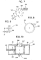
- Fig. 5 illustrates a transmission system for transferring rotational motion in a fluid transfer system according to some embodiments of the present invention.
- Fig. 6 illustrates a transmission system for transferring rotational motion in a fluid transfer system according to some embodiments of the present invention.
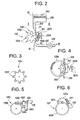
- Fig. 7 illustrates a linear actuator for use with a fluid transfer system according to some embodiments of the present invention.
- Fig. 8 illustrates a piezo-electric actuator for use with a fluid transfer system according to some embodiments of the present invention.
- Fig. 9 illustrates a reusable sensor for a fluid transfer system according to some embodiments of the present invention.
- Fig. 10 illustrates a partial cross sectional view of a depletable unit II according to some embodiments of the present invention.
- Fig. 11 illustrates a partial cross-sectional view of a depletable unit II, having an injection unit III partially engaged therein according to some embodiments of the present invention.
- Fig. 12 illustrates another partial cross-sectional view of the depletable unit II and injection unit III shown in Fig. 11 .
- Fig. 13 illustrates a partial cross sectional view of a depletable unit II according to some embodiments of the present invention.
- Fig. 14 illustrates a partial cross-sectional view of the depletable unit II shown in Fig. 13 , having an injection unit III partially engaged therein according to some embodiments of the present invention.
- Fig. 15 illustrates a trocar of an injection unit III after retraction out of the depletable unit II of Fig. 13 , according to some embodiments of the present invention.
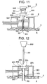
- Fig. 16 illustrates a depletable unit II having a vent tube, and an injection unit III according to some embodiments of the present invention.
- Fig. 17 illustrates a depletable unit II and an injection unit III according to some embodiments of the present invention.
- Fig. 18 illustrates a partial cross sectional plan view of a depletable unit II according to some embodiments of the present invention.
- Fig. 19 illustrates a partial cross sectional plan view of a depletable unit II according to some embodiments of the present invention.
- Fig. 20 illustrates a block diagram of a fluid delivery system according to some embodiments of the present invention.
- Fig. 21 is a schematic diagram of a pressure sensor device according to some embodiments of the present invention.
- Fig. 22 is a schematic diagram of the integration of delivery and receiving contacts into structure of a pressure sensing device according to some embodiments of the present invention.
- Fig. 23 is a graph of a pulse train derived by piezo-electric pressure sensor according to some embodiments of the present invention.
- Fig. 24 is a block diagram of an electronic circuit for a reusable unit according to some embodiments of the present invention.
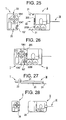
- Fig. 25 is a schematic diagram of a reusable unit I and a depletable unit II, separated, according to some embodiments of the present invention.
- Fig. 26 is a schematic diagram of the reusable unit I and the depletable unit II, connected, according to some embodiments of the present invention.
- Fig. 27 is a side view of an assembled reusable unit I and depletable unit II, positioned next to the skin of a patient, according to some embodiments of the present invention.
- Fig. 28 is a schematic diagram of a reusable unit I and depletable unit II, separated, with injection unit III depicted symbolically (coupled to unit II in the plane of the figure), according to some embodiments of the present invention.
- Fig. 29 is a schematic diagram of the reusable unit I and the depletable unit II shown in Fig. 28 , connected.
- Fig. 30 is a block schematic diagram of a remote control unit IV according to some embodiments of the present invention.
- Fig. 1 is a block diagram of an exemplary system 1000 for implementing a sustained controlled injection (preferably at a predetermined rate) of a liquid into the skin or subcutaneously into the body of a patient.
- body B is regarded as meaning: subcutaneously into the body B, and may also refer to intravenous injection.
- the system 1000 includes a reusable unit I, a depletable unit II, an injection unit III, and a remote control unit IV (unit IV), which preferably are separate units.
- Unit I and unit IV are each reusable, while the depletable unit II and the injection unit III are both preferably disposable and together may form a disposable portion or unit that is discarded after one single use.
- Units I, II and III together forming a fluid dispensing device.
- a user U selects a reusable unit I and a depletable unit II, and programs the system 1000, preferably by use of the remote control unit IV.
- the depletable unit II may then be filled with a desired liquid and upon purging of air be coupled to the reusable unit I.
- An injection unit III is selected and preferably introduced into the depletable unit II.
- the injection unit III may be integral with the depletable unit II.
- units I, II and III are applied onto and preferably adhered to the skin S, while a needle pierces through the skin S, and into the body B.
- Units I and II may be flexible envelopes, possibly transparent, with at least unit II being releasably adherable to the skin S.
- the remote control unit N may then be operated to program the fluid dispensing device to command flow of the liquid from the depletable unit II and into and preferably through the skin S (i.e., subcutaneously) into the body B.
- the user U is either an operator applying the system 1000 on a body, or a patient helping himself.
- unit I may include one or more (and preferably all), generally, of the following components: a control, command and transceiver module 101 (or controller and transceiver 101), for control and communication in the management of fluid injection, and for bi-directional communication with the remote control unit IV.
- a control, command and transceiver module 101 or controller and transceiver 101
- unit I may be an engine 103 for imparting motion to a fluid transfer element 105 of a fluid transfer system, or transfer element 105 for short.
- the fluid transfer system preferably comprises components belonging to both unit I and unit II.
- the fluid transfer system may comprise the engine 103, the fluid transfer element 105, a flexible tube 205 and a backing plate 207, the latter two elements being preferably included in unit II.
- unit I preferably is first coupled to the depletable unit II, to obtain power therefrom, and because the transfer element 105 operates in conjunction with the tube 205 and backing plate 207 contained in unit II.
- the transfer element may have a first, main portion disposed in the first unit I, and a secondary portion disposed in the second unit II.
- first unit I and the second unit II are coupled in operative association, transfer of fluid out of the second unit II may occur, on condition that power is supplied to the engine 103.
- the depletable unit II preferably includes, in general, one or more batteries 201 for powering the reusable unit I, a reservoir 203, which either comes pre-filled with the liquid for dispensing or is filled with the liquid prior to use, tube 205 coupled to the reservoir for delivery of the liquid to a well 206.
- the liquid which is not shown in the figures is injectable only after the injection unit III is coupled to provide fluid communication with the depletable unit II and the injection unit III is inserted into skin S or body B.
- the injection unit III includes mainly a needle 301, which is preferably assembled to other elements, preferably a trocar 303.
- the injection unit III is inserted into the depletable unit II, at well 206.
- Well 206 is coupled in fluid communication with the tube 205.
- the needle 301 is inserted through the well 206 and into the body B through the skin S.
- the trocar 303 may be retrieved and fluid is injected, as dosed and dispensed at a predetermined rate by the fluid transfer system.
- the liquid may be a beneficial fluid or a therapeutic agent.
- each one of the three units I, II, and III may be various types of each one of the three units I, II, and III, where each one type of the same unit (i.e. I, II, or III), being interchangeable and replaceable with the other type.
- the different types of units I, II, and III may all be configured to be releasable coupled for operation.
- diverse types of reusable units I may include a controller and transceiver module 101 with a chosen level of sophistication and optionally, an I/O pad and/or connection, a safety sensor, and may include further options.
- different types of depletable units II may have a reservoir 203 of different size, batteries of diverse capacity, and contain an alternative liquid.
- the injection unit III may have a needle that is shorter, longer, be suitable for insertion at an angle or perpendicularly to the skin, or be of a different kind, according to needs.
- the various components of the reusable units I and of the depletable units II are preferably all disposed as a single layer, arranged and supported on the same plane, and preferably so are their corresponding connections and couplings.
- the two units I and II When assembled and adhered to the skin S, side-by-side along their thickness dimension (i.e., in end-to-end disposition), the two units I and II preferably cover an area not larger than about half the size of a plastic credit card (or smaller), or typically a region measuring about 65mm by about 25 mm.
- Unit III preferably does not add to the covered area.
- Both the reusable unit I and the depletable unit II are preferably hermetically sealed and each may form a flexible envelope that remains sealed even while in use.
- one face or surface of the envelope of unit I and of unit II may be configured for application in mutual assembly to the skin S, as a skin conforming patch, at most some 4 mm high (for example).
- the reusable unit I may be releasably latched to unit II, and at least unit II (but also unit I if desired), may releasably adhere to the skin S.
- the needle 301 may differ in length according to type.
- needle 301 may be sized to penetrate subcutaneously for only 3 mm, or as deep as 30 mm. After removal of the trocar 303, the height of the skin-attached units preferably does not increase.
- the fluid transfer system is a peristaltic positive displacement pump - where the fluid transfer tube 205 squeezes to transfer fluid from the reservoir for injection to the body of the patient.
- the first (main) portion of the peristaltic positive displacement pump, as well as the engine 103 to drive that pump, may be included in unit I.
- the tube 205, the backing 207, the liquid in the reservoir 203, and batteries 201 for driving unit I may be included in the depletable unit II.
- actual injection of the liquid is possible only when at least the units I and II are coupled together for operation.
- Fig. 2 is a schematic illustration showing an edge portion of unit I when attached to unit II, illustrating an exemplary fluid transfer system according to some embodiments of the invention.
- a single toothed wheel, or cogwheel 1051, or gear 1051, with teeth 1053 is appropriately disposed to compress the exterior wall of the flexible tube 205, which is seen be coupled to and exiting out of the reservoir 203.
- the tube 205 is compressed between the teeth 1053 of the gear 1051 and backing 207 disposed adjacent and tangentially to the gear 1051.
- the backing may comprise a flat or curved back plate 207.
- the backing 207 is loaded by a spring 2070 biased against a static base 2074.
- a quantum of fluid 1055 trapped between two adjacent teeth 1053 of the gear 1051, is transferred along the tube. Transfer of liquid occurs from an upstream suction side 31, adjacent the reservoir 203, to a discharge side 33 downstream of the transfer element 105, leading the liquid to well 206, and eventually to the needle in unit III.
- the flexile tube 205 extends between the reservoir 203 and the well 206.
- engine 103 may be operated continuously, or at appropriately selected time intervals, according to the rate of fluid to be dispensed.
- the fluid transfer system including the gear 1051, backing 207, and teeth 1053, substantially guarantees and preferably permanently prevents a direct flow, in either or both directions, to the suction side 31 or the discharge side 33, thereby enhancing safety of use. Accordingly, such fluid transfer systems, according to some embodiments of the present invention, allow control of the direction of flow of the fluid without requiring valves; as long as at least one tooth 1053 completely compresses the tube 205 and blocks the passage of liquid, no valves are required. Use of the foregoing positive displacement pump is not associated with backpressure , and thus, backpressure drop will not occur.
- the dispenser delivers the infused fluid in discrete, equal-sized volumes of between about 0.2 - 1 of 10 -4 cc per roller or tooth 1053.
- Flow rate may therefore be provided in minute quanta and can be precisely controlled simply by regulating the speed of rotation of the wheel 1051. In other words, flow rate can be measured simply by counting rollers, or teeth, as they rotate past the tube 205.
- at least one roller, or tooth 1053 preferably always depresses tube 205, which substantially eliminates (and preferably eliminates) a hydraulic "short circuit" (i.e., direct communication between the reservoir and the well 206).
- "n" ranges from 0 to a maximum
- v t is defined according to the selected configuration of the cogwheel 1051.
- High accuracy of the quantity of transferred liquid may thus be achieved by programming the controller and transceiver 101, to appropriately control the parameter n for a given v t .
- the reservoir 203 is preferably configured either as a flexible container 203, or as a resilient collapsible and expandable bladder 203 (or other collapsible fluid retention device).
- the reservoir 203 may include a self-sealing filling port 2031, permitting a user U to fill the reservoir using a syringe (not shown in the drawings). To that end, the user U selects a desired liquid, and fills the syringe. Then, the needle of the syringe is used to pierce the self-sealing filling port 2031 of the reservoir 203, and the selected liquid is injected into the container 203, or bladder 203, which expands during filling up to a maximal volume.
- the user U may manually purge air out of the unit II prior to using the device.
- the syringe is evacuated from the filling port 2031, which self-seals the reservoir.
- the reservoir 203 is preferably manufactured integrally with the tube 205, or hermetically attached thereto by virtue of a conventional connector (not shown in the figures).
- the reservoir 203 may be provided readily pre-filled from factory.
- the expansion of the bladder 203 may be limited, say by a cage or by an enclosure not shown in the figures, or left free to expand until arrested by a component of unit II or a housing thereof. In some embodiments, when left free, the bladder 203 may expand in all directions and penetrate into available interstices, even filling gaps remaining open between components, taking maximum advantage of unused space.
- the separation line SL indicates the abutting edges of unit I and unit II, clearly illustrating that fluid transfer will not occur when units I and II are separated, because the wheel 1051 will be distanced away from the tube 205, and the engine 105 will be deprived of power received from the batteries 201.
- Each unit may comprise a specific type for a specific application/treatment.
- each type may be distinguished from another by, for example, fluid contents, a reservoir 203 of chosen size, and/or batteries of given power.
- Fig. 3 illustrates another embodiment of the wheel 1051, with freewheeling rollers 1057 supported at the extremities of all the teeth 1053, to provide for low rolling friction.
- Fig. 4 depicts a partial cross-section of a further embodiment, where the rollers 1057 are supported freely and rotatably between two plates 1059.
- the outer circumference of the plates 1059 may exceed that of the rollers 1057, so that the diameter of the tube 205 is partially or completely disposed between the two plates 1059.
- the plates 1059 may be geared for engagement with other geared driving means. If desired, only one plate 1059 with rollers 1057 is sufficient. Other embodiments of support plate are possible.
- Fig. 5 illustrates an example of a transmission of rotational motion from the motor 105, via reduction gears, to a gear 1051 or to a geared plate 1059.
- the engine 103 here motor 103, drives a first spur gear 1061 that engages a second spur gear 1063 of diameter larger than that of gear 1061.
- a third spur gear 1065 concentrically fixed to and of diameter smaller than that of the second spur gear 1063, engages a fourth spur gear 1067, of diameter larger than that of the third spur gear 1065, to which a worm gear 1069 is affixed concentrically.
- the worm gear 1069 rotates the gear 1051.
- Fig. 6 is another example of a gear train reduction mechanism.
- the motor 103 drives a worm gear 1071, which engages a spur gear 1073 having a concentrically mounted smaller diameter spur gear 1075 affixed thereto. That last spur gear 1075 rotates the gear 1051 or the plate 1059.
- Other transmission configurations are possible, by friction, gears, and flexible shafts, for example.
- Fig. 7 presents a linear actuator 1081, such as a solenoid, with a reciprocating plunger 1083 striking a tooth 1053 to drive the wheel 1051 counterclockwise.
- a linear actuator 1081 such as a solenoid
- Fig. 8 shows a piezoelectric actuator 1081 tangentially engaging a tooth 1053 on the periphery of a wheel 1051 or plate 1059 for providing counterclockwise rotation.
- a pulse of power causes the piezoelectric actuator 1081 to deliver one tangential strike to a tooth 1053, and to rotate the wheel 1051.
- transmission and reduction mechanisms may also be possible, which may utilize planetary, rolling, and friction gears, rack and teeth mechanisms, and belts, whether alone or in combination.
- a simple reusable sensor may be optionally mounted on unit I.
- Fig. 7 shows schematically a reusable sensor 21 which may be used in embodiments of the present invention and which is disposed opposite a tooth 1053, in the plane of the wheel 1051.
- One or more leads 23 connect between the sensor 21 and the controller and transceiver 101.
- the reusable sensor 21 is selected as an appropriate component of a type known in the art, such as capacitive, inductive, magnetic, mechanic, or optic sensor, or a combination thereof.
- the reusable sensor 21 is disposed opposite a tooth 1053, as shown in Fig. 9 .
- the controller and transceiver 101 may compare the commanded rotation rate of the wheel 1051 with the output of the reusable sensor 21, and emit correction signals to the transfer element 105 (if necessary).
- an arrow coupling from the transfer element 105 to the controller and transceiver 101 indicates feedback, for use in some embodiments, allowing the controller to respond accordingly when necessary. The reliability of the system 1000 is thereby enhanced.
- the batteries 201 in unit II are electrically connected to delivery contacts 2209, which may be appropriately disposed to couple with the receiving contacts 107 disposed in unit I.
- the receiving contacts 107 may be connected to the controller and transceiver 101, and to the engine 103, which actuates the fluid transfer element 105.
- unit II is discarded and replaced, while unit I may be reusable.
- Fig. 10 is a partial cross-section of a portion of the depletable unit II according to some embodiments, showing the envelope 2001, the downstream extremity 2051 of the flexible tube 205, which is coupled in fluid communication to the well 206.
- the well 206 When the well 206 is filled with the liquid it may be supplied for injection via the injection unit III.
- the well 206 functions as a receptacle for the liquid and it is provided with a tube inlet 2061 to which the downstream extremity 2051 of the tube 205 is attached, with an entry aperture 2063, and with an exit aperture 2065.
- the entry aperture 2063 and the exit aperture 2065 are preferably releasably and hermetically sealed by, respectively, an entry plug 2067 and an exit plug 2069.
- a peel-off label, or other sealing means, may be provided instead of the entry plug 2067 and the exit plug 2069.
- the well 206 may extend from the entry aperture 2063 to the exit aperture 2065, being substantially directed across the whole height of unit II, and may also be perpendicular to the tube 205.
- the exit aperture 2065 may be flush with the proximal surface of unit II to be adhered to the skin S, and the entry port 2063 may open on the opposite surface of unit II, which is the distal surface, pointing away from the skin. This disposition of the well 206 may be considered as a vertical disposition.
- the depletable unit II With liquid in the reservoir 203, and before using the system 1000, the depletable unit II is coupled to the reusable unit I. Then, as shown in Fig. 10 , the exit plug 2069 may be removed, whereby the exit opening 2065 is exposed and permits passage of liquid.
- command is provided, say, by use of the remote control unit IV, to enable the dispenser device pump to urge liquid out of the reservoir 203 and into the well 206 via the flexile tube 205 extending between the reservoir and the well.
- liquid is released through the exit opening 2065, so that when unit II is held (appropriately), with the exit aperture 2065 turned upwards (for example), air will be purged out of the unit II.
- air may be purged manually, prior to coupling, as described hereinabove.
- the entry plug 2067 may be removed so that both the entry aperture 2063 and the exit aperture 2065 may be open to permit free introduction of the injection unit III into the well 206.
- Fig. 11 shows an example of an injection unit III partially engaged into the depletable unit II.
- the sharp tip 3031 terminates the penetrating extremity of the trocar 303, shrouded by a cannula 305. It is seen that the cannula, has already pierced through the skin S.
- the injection unit III For piercing the injection unit III is preferably translated toward and into the unit II, until it is fully engaged and seated therein, and then the trocar 303 is retrieved out and away from the injection unit II, and discarded.
- a handle 3033 may be fixedly attached to the trocar 303.
- the handle 3033 itself, as a separate part, is not essential in embodiments of the present invention since the grip extremity 3035 of the trocar 303 may be formed as a handle, for example, as a hook or as a ring.
- the trocar 303 may have a solid cross-section as a dagger, or be hollow for air purging purposes (for example).
- the cannula 305 is open at the skin-contacting extremity 3051 and is preferably firmly attached to a plug 3053 at the opposite extremity.
- the plug 3053 may be configured with a rim 3055 to permit only a single one-way insertion via the entry opening 2063 of unit II.
- At least one radial bore 3057 may be provided into the cannula 305 to permit fluid communication from the interior of the well 206 into the lumen of the cannula.
- Fig. 12 depicts the cannula 305 when inserted into the body B and fully seated in unit II, with the trocar being already retrieved.
- the cannula 305 may be anchored by the plug 3053 in the interior of a trap 2071 formed in unit II.
- the plug 3053 may be captive between the extension 2073, at the rim 3055, and the step 2075.
- the plug 3053 seals liquid flowing into the well 206 via the tube 305, to keep it from spilling out of the entry opening 2063.
- the spilling of fluid out of the exit opening 2065 is prevented by the envelope 2001 acting as a seal, or by a dedicated exit seal 2073, or by both.
- the viscoelastic envelope 2001 it is possible to use the viscoelastic envelope 2001 to seal the entry opening 2063.
- liquid contained inside the well 206 is prevented from escaping via the entry opening 2063 and/or the exit opening 2065, but may flow into the cannula 305 via the radial bore 3057 and out of the cannula via discharge opening 3059. Accordingly, liquid transferred out of the reservoir 203 is provided for injection into the skin S or the body B of the patient.
- Fig. 13 is another embodiment of a well, showing a well 206 with an entry aperture 2063 and an exit aperture 2065.
- the well entry aperture 2063 is disposed adjacent the distal surface opposite an entry port 2003 provided in the envelope 2001.
- the entry port 2003 is blocked by an entry seal 2085, which may be either simply a portion of the envelope 2001, or be a viscoelastic seal embedded in the envelope as an insert.
- the entry seal 2085 may be manufactured by double-injection or by a similar production technique.
- the well exit aperture 2065 is preferably disposed adjacent the proximal surface, opposite the entry port 2003 provided in the envelope 2001. It is through the exit aperture 2065 that air may be purged.
- Fig, 14 illustrates another embodiment of an injection unit III that has been inserted into the well 206 shown in Fig. 13 .
- the needle 301 may include a ram 3038 disposed intermediate the handle 3033 and the cannula 305, which is fitted with the trocar 303.
- One side of the ram 3038 may be fixedly attached to the handle 3033, and the opposite side of the ram, may be fixedly attached to the trocar 303.
- the ram 3038 drives the cannula 305 until the handle 3033 is arrested by abutment on unit II. In that arrested position, which is depicted in Fig. 14 , the cannula 305 is retained in place by friction at the well 206 and at unit II.
- Fig. 15 shows the trocar 303 after retraction out of the depletable unit II, and ready to be discarded.
- the cannula 305 is retained into the body B enabling for liquid to flow out of the tube 205, into the well 206, and from there, into the cannula inlet opening 3063, via the cannula discharge opening 3059, and into the body.
- the entry aperture 2063 and the exit aperture 2065 may be appropriately sealed to assure flow of liquid only via the cannula 305, thus to prevent unwanted escape and loss of liquid out of the well 206.
- Fig. 16 shows a well 206 featuring a vent tube 2091 with a vent tube inlet 2093, and a vent tube outlet 2095, providing for fluid communication from the interior of the well 206 to the exterior of the envelope 2001.
- the vent tube 2091 may be inserted into the well 206 and the envelope 2001; the well and envelope may be made of viscoelastic material to seal fluid exit but via the lumen of the vent tube 2091.
- a cap may be included for covering the vent tube outlet 2095, but it is not shown in the figures, since it is removed prior to use. If desired, an entry seal 2085 may be appropriately disposed in the envelope 2001. As described hereinabove, air may be purged before or after coupling of the reusable unit I with the depletable unit II.
- an embodiment of the injection unit III is the same as that of Figs. 14 and 15 .
- the trocar 303 and the cannula 305 pierce both the envelope 2001 and the well 206, and also pierce the entry seal 2085, if it is mounted.
- the bottom portion 3037 of the handle 3033 pushes the vent tube 2091 into the well 206 and seals the vent tube outlet 2095.
- the cannula 305 is retained in position due to friction, as described hereinabove with reference to Figs. 14 and 15 .
- Fig. 17 shows a cannula 305 driven by a cannula driver 3039 that is fixedly retained to the handle 3033 of the trocar 303.
- the cannula driver 3039 is affixed to the handle 3033 and to the trocar 303 instead of the ram 3038 shown in Figs. 14, 15 , and 16 .
- the cannula driver 3039 operates in association with a cannula 305 having a male screw thread 3058 disposed on the exterior portion adjacent the cannula inlet opening 3063.
- the cannula driver 3039 may be configured to engage the cannula inlet opening 3063 or a portion of the cannula adjacent thereto, to allow longitudinal insertion into the well 206, and rotation of the cannula.
- the trocar 303 is preferably linearly driven into the well 206 and then rotated to engage the screw thread 3058, either in self-tapping mode, or to engage a matching female screw thread appropriately provided, in the exit opening 2065.
- the trocar handle 3033 may be pulled out of the unit II, which may also retrieve the cannula driver 3039.
- the cannula inlet 3063 is now open to permit transfer of liquid from the well 206 to the skin S or body B.
- the cannula 305 is shown for insertion in perpendicular direction into the skin S.
- other configurations may be possible which permit insertion of the cannula 305 at other desired angles.
- Fig. 18 depicts still further embodiment of the dispenser, which is provided with a rotary joint 60 allowing rotation of the injection unit III in both clockwise and anticlockwise direction, for insertion of the cannula 305 at any angle from 0° to n360°, with n ranging from 0 to ⁇ .
- insertion may be made at an angle ranging between the vertical and horizontal direction of the cannula relative to the skin S.
- Fig. 18 is a partial cross-section of a plan view of unit II, showing the downstream extremity 2051 of the flexible tube 205 fixedly coupled in fluid communication with the entry aperture 2063 of the well 206.
- the well 206 is disposed in a horizontal position, being substantially parallel with the skincontacting surface of unit II.
- the entry aperture 2063 preferably opens into a trap 2071 forming a cavity for liquid accumulation.
- the cavity is restricted by a step 2075 to form a cylindrical exit aperture 2065 of the well 206 that emerges onto a side wall or height surface of unit II. contrast, with the well shown in Figs. 10 to 17 , the entry aperture 2063 is concealed and contained in the interior of unit II.
- the rotary joint may be provided with a rotary fastener 61 coupled with the exit aperture 2065 of the well 206
- An exterior portion 62 of the rotary fastener 61 supports an entry seal 2085 and a cannula 305, which is provided with a radial bore 69.
- the cannula is directed perpendicularly with respect to the well 206.
- the rotary fastener is provided with an internal channel, which provides fluid communication with the well and with the radial bore 69 of the cannula.
- the rotary fastener 61 includes an interior portion 63 terminating by resilient expandable jaws 65, and a cylindrical stem 66 intermediate the exterior portion 62 and the jaws 65.
- the interior portion 63 of the rotary fastener 61 is preferably retained within the cylindrical exit aperture 2065.
- the resilient jaws 65 may be prevented from exiting out of the trap by virtue of the step 2075 and the stem 66 may be rotated in the cylindrical exit aperture 2065.
- An O-ring seal 64 intermediate the cylindrical exit aperture 2065 and the stem 66 prevents leakage of fluid.
- the rotary fastener 61 may thus be free to rotate relative to the well 206 and the unit II.
- a tongue 67 may be fixedly attached to the unit II for accommodating within grooves 68 cut on the periphery of the exterior portion 62 of the rotary fastener 61.
- the cannula 305 Before introduction of a "dagger" trocar 303 fitted with a handle 3033, and upon filling the reservoir 203 and purging out of air, the cannula 305 may serve for the exit of liquid. However, it is also possible to purge air when the cannula 303 is fitted with the trocar 303. To that end, the trocar 303 is hollow, and is provided with a radial bore 69 for liquid communication with the well 206 and with the exterior of unit II.
- Fig. 18 the cannula 305 is received within the fastener 61 and is situated inside a cutout 71 provided in the unit II
- Fig. 19 A different embodiment of the rotary joint is shown in Fig. 19 , in which the second unit is not provided with the cutout 71.
- the tongue 67 and the grooves 68 may be disposed slightly differently.
- unit III may be configured differently.
- unit III may include a dagger trocar 303 fitted with a handle 3033, or including a hollow trocar 303 with a handle 3033.
- Unit III may take advantage of any of the embodiments depicted in the Figs 11 to 17 .
- the unit III includes rotary fastener 61 with the trocar 303 and the cannula 305 already inserted therein.
- the well 206 may be fitted with an exit plug 2069, which may be removed for air purging.
- Fig. 20 shows optional components for integration with the reusable unit I, as embodiment 2000.
- Such options may include an Input/Output pad 101, or I/O pad 102, a safety device 104, an alarm 106, and one or more rechargeable batteries 108.
- the I/O pad 102 may be fitted with input means such as button(s) and/or keys, or a USB port, and output means such as LEDs, and even with a display if desired.
- the I/O pad 102 is coupled to, and receives input and output commands from both, the controller and transceiver 101, and from the user U.
- a safety device 104 may be coupled to an independent flow sensor configured to monitor the fluid pressure pulses delivered to the downstream extremity 2051 of the flexible tube 205.
- the safety device 104 may directly sense pulses of liquid pressure generated in the tube 205.
- the addition of a stand-alone fluid flow sensor, not shown in the figures, may be added if desired, to enhance the reliability of the system 1000.
- Fig. 21 is a schematic presentation of an exemplary pressure sensor device.
- the tube 205 is seen in cross-section, supported by a rigid base 2011 carried by the dispensable unit II, while a rigid bridge 1041 disposed on the reusable unit I, embraces the tube 205.
- the bridge may include on or more legs, and preferably, two legs 1043, distanced and separated apart, both legs may be supported on the base 2011, and one beam 1045 supported by the two legs 1043.
- the separation line SL in Fig. 21 indicates a border between unit I and unit II, and thus marks the separation line between the bridge 1041 and the base 2011.
- a piezoelectric pressure sensor 1047 may be retained in the beam 1045 disposed opposite the base 2011 to be in direct mechanical contact with the tube 205.
- the piezoelectric pressure sensor 1047 senses that pulse, which is translated into an electrical signal communicated via a couple of leads 1049 to the controller and transceiver 101.
- Fig. 22 shows schematically an advantage taken from the disposition of the two legs 1043 to integrate both the delivery and receiving contacts, respectively 2209 and 107, into the structure of the pressure sensor device 1047.
- a receiving contact 107 may be disposed in the free extremity 1044 of each leg 1043, and a delivery contact 2209 may be disposed in opposite thereto on the base 2011.
- a lead 1048 may be electrically coupled to each receiving contact 107 passing in the interior of each leg 1043.
- a lead 2013 may be electrically coupled to each delivery contact 2209 passing through the base 2011.
- each one or both contacts out of a pair comprising a delivery contact 2209 and a receiving contact 107 may be springloaded for better conductance, if desired.
- the piezoelectric pressure sensor 1047 which responds by emitting signals in proportion to trains of quanta of fluid 1055 flowing through the tube 205, may easily detect basal and bolus fluid flow patterns, and report accordingly to the controller and transceiver 101. Furthermore, high pressure, such as caused by an occlusion, or low pressure, such as caused by a leak, i.e. disengagement or rupture, will also easily be detected and reported.
- each pulse may be characterized by an amplitude A, by a pulse width w, and by a distance T separating two consecutive pulses, indicative of the period T.
- Fig. 23 shows a graph as an example of a pulse train derived by the piezoelectric pressure sensor 1047, with respect to a set of coordinates having an abscissa t, indicating time, and an ordinate y designating amplitude.
- the pressure pulse waveform contains information regarding the operational status of the system 1000, say as represented by the three parameters A, w, and T.
- the amplitude A may be proportional to the pressure of the liquid in the tube 205, and preferably remains within predetermined boundaries. Too high an amplitude A, thus too high a pressure, may indicate an occlusion. On the contrary, low pressure may point to a leak, such as a rupture, release, disconnection, or even lack of liquid.
- the period T may be proportional to the speed of rotation of the wheel 1051 of the transfer element 105, thus proportional to the volume of injected quanta of liquid.
- the coefficient k is an empirical one-dimensional coefficient, and depends on the interior diameter of the tube 205.
- the safety device 104 is a valuable independent support tool enhancing the reliability of the system 1000 regarding the delivery of alarm in case a trend pointing to a developing dangerous situation or to an imminent danger is detected in some embodiments of the invention.
- one or more safety devices 104 may be added, such as a flow sensor, in replacement of, or in addition to the pressure sensor 1047.
- An alarm module 106 may be provides, which may be coupled to the receiving contacts 107 providing power, and to the controller and transceiver 101.
- the alarm module 106 may be used to provide alert in response to a danger signal emitted by the controller and transceiver 101, and/or by the safety device 104.
- the alarm module 106 may be implemented to emit an audible, visual, or sensory signal, by operation of, respectively, a buzzer, a light, or a vibrator.
- the vibrator is the preferred implementation since unit I is disposed on the skin S, also preferred because the delivered signal is a privately sensed one, without the surroundings being aware thereof.
- An alarm may be given in response to a signal from the controller and transceiver 101, according to at least one of the following: a detected unacceptable condition and performance of the engine 103, a signal from the reusable sensor 21, or a signal from the safety device 104.
- the safety device 104 may be coupled to the alarm module 106 via the controller and transceiver 101, or directly thereto, even though such a connection is not shown in the figures.
- the engine 103, the safety device 104, and the transfer element 105 are activated only after operative connection of the reusable unit I with the depletable unit II is established.
- the controller and transceiver 101 may emit wireless alarm signals to the remote unit IV, which may relay those alarm signals to other external receiving devices, computers, and networks.
- a battery possibly a rechargeable battery 108, is also integrated within the reusable unit I, to provide additional reliability to the system 1000.
- the battery 108 may be charged by connection to an external battery charger via a charging port.
- controller and transceiver 101 are shown coupled to the I/O pad 102, the engine 103, the safety device 104, the transfer element 105, the alarm 106, and in bi-directional wireless communication with the remote control unit IV.
- the controller and transceiver 101 may be microprocessor-driven for commanding and managing units I and II, and configured to support bi-directional wire and wireless communication with the remote control unit IV.
- Fig. 24 illustrates an exemplary block diagram presenting the electronic circuit of the controller and transceiver 101, which is a control-with-transceiver module.
- a microprocessor 1011, or ⁇ P 1011, having one or more memories 1012, is coupled to a transceiver 1013 having an antenna 1014.
- the ⁇ P 1011 may also be coupled to an engine driver 1015, an A/D converter 1016, which in turn, is coupled to a MUX 1017.
- the ⁇ P 1011 may be configured to read, operate and run computer programs stored in the one or more memories 1012, referred to hereinbelow as the memory 1012, as well as to respond to instructions and commands.
- the ⁇ P 1011 receives commands from the remote unit IV via the antenna 1014 and the transceiver 1013, then fetches data and computer programs from the memory 1012, and stores data therein.
- the transceiver 1013 also preferably communicates with the memory 1012 to store programs and data therein and to retrieve data therefrom. It is via the antenna 1014 that the transceiver 1013 communicates with the remote control IV, and if desired, with other receivers, emitters or transceivers, not shown in the figures.
- the ⁇ P 1011 may then emit commands to the engine driver 1015 for activation of the engine 103, and receives feedback from one or more safety device(s) 104. From the received feedback, the ⁇ P 1011 may derive comparisons, and may, if necessary, emit correction commands to the engine driver 1015.
- Feedback signals from the safety device(s) 104, received from analog sensors, may be fed to the ⁇ P 1011 via a MUX 1017, and converted by an A/D converter 1017 into digital signals.
- data and commands may be exchanged between the ⁇ P 1011 and the I/O pad 102.
- the ⁇ P 1011 may also activate the alarm 105 when necessary.
- Power for running the ⁇ P 1011 may be obtained from the receiving contacts 107 coupled to batteries mounted in unit II, or to an optional battery 108, rechargeable or not, mounted on unit I.
- the electronic circuit of the controller and transceiver 101 may be integrated in a manner well known to the art, as a low power-consuming single chip, such as an ASIC, i.e. Chipcon®, Zarlink®, and the like.
- Fig. 25 shows unit I and unit II separated from each other, while unit III is depicted symbolically as being coupled to unit II, even though shown in the plane of the paper instead of being in perpendicular thereto.
- Unit II may include releasable latching arms 21 and a recess 23 to receive unit I.
- Unit I may include latching grooves 22 configured to engage the latching arms 21, to firmly but releasably retain both units I and II together.
- both the wheel 1051 and the sensor 1047 when both units I and II are latched together, both the wheel 1051 and the sensor 1047 appropriately abut the tube 205, and likewise, the delivery contacts 2209 engage the receiving contacts 107.
- Fig. 26 is a side elevation of the latched units I and II.
- a strip of peel-off tape 24 covers a layer of adhesive 25. With the tape 24 taken off, the unit II may be brought in contact with the skin S, not shown in Fig. 27 , to adhere thereto. If desired, but not shown in Fig. 26 , adhesive may be added to unit I in the same fashion as described for unit II.
- Fig. 28 presents another embodiment, which also shows unit I and unit II separated from each other, while unit III is again depicted symbolically as being coupled to unit II in the plane of the paper instead of being in perpendicular thereto.
- Unit II is shown to have a cradle 28 for releasably receiving unit I therein.
- Fig. 29 depicts unit I securely snapped into the cradle 28, but releasable therefrom when depleted.
- the bottom of unit I may also be covered with peel-off tape 24 covering a layer of adhesive.
- An O-ring 29, or other sealing element 29, may be coupled to unit I to ensure sealing when engaged with unit II.
- Fig. 30 is a block diagram of an example of the remote control unit IV, which is a handheld set operated by the user U.
- the remote control unit IV is the user interface with the system 1000, by which programs and/or commands are emitted and received, and the system 1000 is operated and controlled.
- microprocessor-driven command and control unit 401 able to run computer programs stored in a memory 403, is coupled to a transceiver 405, which in turn is coupled to an antenna 407, for wireless bi-directional communication with at least unit I. Communication with external deices, computers, and networks is also possible, if desired.
- the command and control unit 401 may also be coupled to a display 409, and to an alphanumeric keyboard 411.
- An alarm device 415 such as a LED, a buzzer, or other known devices, may further be coupled to the command and control unit 401.
- Exchange of information, such as computer programs, memory data, instructions, and commands is achieved with the system 1000 (for example), and with other external and remote devices, computers, and networks, not only via the transceiver 405, but also via an Infra Red port 421, or IR port 412, and a USB port 423.
- Power for operation of the remote control unit IV may be supplied by a battery 425, which is replaceable, or reloaded via a battery charge port 427.
- the battery may power the command and control unit 401, the transceiver 405, the display 409, and the alarm device 415. It is noted that the battery 425, the memory 403, the USB port 423, and the alarm 415, shown as single devices on Fig. 30 , may be implemented as multiple devices if desired.
- the memory 403 of the remote control unit IV may be loaded with programs via the transceiver 405, or via the IR port 421, or via the USB port 423.
- the user U may enter instructions and commands via the keyboard 413, to communicate via the transceiver 405 and the antenna 407,with the controller and transceiver 101 of the reusable unit I.
- Information received from sources external to the units of the system 1000, as well as data received from unit I, may be displayed on the display 409.
- the command and control unit 401 may analyze system status and receive data for output of selected information and necessary alarms on, respectively, the display 409 and the alarm 415.
- the display 409 may also be able to show various status data, such as liquid delivery rate, computer program actually running, and battery state.
- the exchanges of data and the communication processes may be governed by known techniques ensuring data security and data integrity, and taking advantage of known handshaking and secured communication protocols, all well known to the art.
- Fig. 31 illustrates a handset I/O pad disposed on the remote control unit IV, showing the display 409, the keyboard 411, and the alarm 415.
- the user U selects a liquid to be injected, such as insulin for example, and further chooses a desired type of unit II. If the reservoir 203 in unit II is not supp lied pre-filled, the user U may manually fill the reservoir 203, taking care of purging air therefrom. Then, unit II with the reservoir 203 is operatively coupled to the reusable unit I. The user U now selects a type of unit III, as desired, or as needed. In turn, unit III is inserted into unit II to establish fluid communication therewith, whereafter the user U commands operation of the transfer element 105 to purge air out of the cannula 305. Next, unit III is operated for insertion of the cannula 305 into the skin S or subcutaneously into the body B, and the operationally assembled units I, II, and III are appropriately disposed for at least unit II to adhere to the skin.
- a liquid to be injected such as insulin for example
- controller and transceiver 101 may execute computer programs and instructions as commanded by the user U, via unit IV, or via the I/O pad 102. Computer programs and instructions may also be deliverable to the controller and transceiver 101 as captured from an external source. Emissions from external sources may be captured by unit IV through the wireless transceiver 405, via the antenna 407, or the IR port 421, or by wire via the USB port 423. Such external transmissions may be received from devices external to the system 1000, from remote computers or networks.
- liquid is dispensed from the reservoir 203 according to computer programs stored in memory, or in response to command from the user U.
- the engine 103 activates the transfer element 105 in associative operation with the tube 205 and the backing 207, to fill the well 206.
- Unit III forwards liquid from the well 206 and into the skin S or subcutaneously into the body B.
- Faultless operation of the system 1000 may be monitored by the controller and transceiver 101, and to enhance reliability, also supported by feedback signals received from a reusable sensor 21 disposed on the transfer element 105, and/or from the safety device 104 coupled to disposable sensors disposed on unit II.
- At least one rechargeable battery may be disposed in unit I.
- the system 1000 is thus an example of a sustained release delivery system for delivering a beneficial liquid at a predetermined rate to the skin S or body B.
Priority Applications (2)
| Application Number | Priority Date | Filing Date | Title |
|---|---|---|---|
| EP11156831.7A EP2332595B1 (fr) | 2005-11-07 | 2006-11-05 | Pompe à perfusion portable modulaire |
| DK11156831.7T DK2332595T3 (da) | 2005-11-07 | 2006-11-05 | Bærbar modulinfusionspumpe |
Applications Claiming Priority (2)
| Application Number | Priority Date | Filing Date | Title |
|---|---|---|---|
| IL17181305 | 2005-11-07 | ||
| EP06809836.7A EP1945285B2 (fr) | 2005-11-07 | 2006-11-05 | Pompe de perfusion modulaire ambulatoire |
Related Parent Applications (2)
| Application Number | Title | Priority Date | Filing Date |
|---|---|---|---|
| EP06809836.7A Division-Into EP1945285B2 (fr) | 2005-11-07 | 2006-11-05 | Pompe de perfusion modulaire ambulatoire |
| EP06809836.7 Division | 2006-11-05 |
Related Child Applications (1)
| Application Number | Title | Priority Date | Filing Date |
|---|---|---|---|
| EP11156831.7 Division-Into | 2011-03-03 |
Publications (3)
| Publication Number | Publication Date |
|---|---|
| EP2283882A2 true EP2283882A2 (fr) | 2011-02-16 |
| EP2283882A3 EP2283882A3 (fr) | 2011-09-07 |
| EP2283882B1 EP2283882B1 (fr) | 2013-06-05 |
Family
ID=37685309
Family Applications (3)
| Application Number | Title | Priority Date | Filing Date |
|---|---|---|---|
| EP10190099.1A Active EP2283882B1 (fr) | 2005-11-07 | 2006-11-05 | Pompe de perfusion modulaire ambulatoire |
| EP11156831.7A Active EP2332595B1 (fr) | 2005-11-07 | 2006-11-05 | Pompe à perfusion portable modulaire |
| EP06809836.7A Active EP1945285B2 (fr) | 2005-11-07 | 2006-11-05 | Pompe de perfusion modulaire ambulatoire |
Family Applications After (2)
| Application Number | Title | Priority Date | Filing Date |
|---|---|---|---|
| EP11156831.7A Active EP2332595B1 (fr) | 2005-11-07 | 2006-11-05 | Pompe à perfusion portable modulaire |
| EP06809836.7A Active EP1945285B2 (fr) | 2005-11-07 | 2006-11-05 | Pompe de perfusion modulaire ambulatoire |
Country Status (14)
| Country | Link |
|---|---|
| US (3) | US7935104B2 (fr) |
| EP (3) | EP2283882B1 (fr) |
| JP (1) | JP4999855B2 (fr) |
| KR (1) | KR101290983B1 (fr) |
| CN (3) | CN101340938B (fr) |
| AT (1) | ATE495773T1 (fr) |
| AU (1) | AU2006310103B8 (fr) |
| BR (1) | BRPI0618320A2 (fr) |
| CA (1) | CA2627787C (fr) |
| DE (1) | DE602006019764D1 (fr) |
| DK (3) | DK1945285T4 (fr) |
| HK (2) | HK1176893A1 (fr) |
| RU (1) | RU2008117462A (fr) |
| WO (1) | WO2007052277A1 (fr) |
Cited By (1)
| Publication number | Priority date | Publication date | Assignee | Title |
|---|---|---|---|---|
| US11065381B2 (en) | 2015-10-05 | 2021-07-20 | E3D A.C.A.L. | Infusion pump device and method for use thereof |
Families Citing this family (251)
| Publication number | Priority date | Publication date | Assignee | Title |
|---|---|---|---|---|
| US8034026B2 (en) * | 2001-05-18 | 2011-10-11 | Deka Products Limited Partnership | Infusion pump assembly |
| DK1390089T3 (da) | 2001-05-18 | 2007-05-29 | Deka Products Lp | Infusionssæt til væskepumpe |
| US6852104B2 (en) | 2002-02-28 | 2005-02-08 | Smiths Medical Md, Inc. | Programmable insulin pump |
| US8137314B2 (en) * | 2006-08-23 | 2012-03-20 | Medtronic Minimed, Inc. | Infusion medium delivery device and method with compressible or curved reservoir or conduit |
| US7794427B2 (en) | 2005-09-26 | 2010-09-14 | Asante Solutions, Inc. | Operating an infusion pump system |
| US8105279B2 (en) | 2005-09-26 | 2012-01-31 | M2 Group Holdings, Inc. | Dispensing fluid from an infusion pump system |
| US7534226B2 (en) | 2005-09-26 | 2009-05-19 | M2 Group Holdings, Inc. | Dispensing fluid from an infusion pump system |
| US8551046B2 (en) | 2006-09-18 | 2013-10-08 | Asante Solutions, Inc. | Dispensing fluid from an infusion pump system |
| US7935104B2 (en) * | 2005-11-07 | 2011-05-03 | Medingo, Ltd. | Systems and methods for sustained medical infusion and devices related thereto |
| US11497846B2 (en) | 2006-02-09 | 2022-11-15 | Deka Products Limited Partnership | Patch-sized fluid delivery systems and methods |
| US11478623B2 (en) | 2006-02-09 | 2022-10-25 | Deka Products Limited Partnership | Infusion pump assembly |
| CN109621078B (zh) * | 2006-02-09 | 2022-05-27 | 德卡产品有限公司 | 用于控制可配戴医疗器件的系统 |
| US11364335B2 (en) | 2006-02-09 | 2022-06-21 | Deka Products Limited Partnership | Apparatus, system and method for fluid delivery |
| WO2007106557A2 (fr) | 2006-03-14 | 2007-09-20 | University Of Southern California | Dispositif mems et procede de livraison d'agents therapeutiques |
| EP2026862B1 (fr) * | 2006-06-08 | 2019-08-14 | Roche Diabetes Care GmbH | Système pour détecter une occlusion dans un tube |
| DK2365452T3 (da) * | 2006-07-07 | 2020-11-16 | Hoffmann La Roche | Væskeindgivelsesanordning og fremgangsmåder til drift deraf |
| ATE540663T1 (de) | 2006-08-18 | 2012-01-15 | Medingo Ltd | Verfahren und vorrichtungen zur abgabe einer flüssigkeit an ein reservoir einer flüssigkeitsabgabevorrichtung |
| US7789857B2 (en) | 2006-08-23 | 2010-09-07 | Medtronic Minimed, Inc. | Infusion medium delivery system, device and method with needle inserter and needle inserter device and method |
| US20100298764A1 (en) * | 2006-09-06 | 2010-11-25 | Ofer Yodfat | Fluid delivery system with optical sensing of analyte concentration levels |
| DK2083673T3 (da) | 2006-09-29 | 2012-09-24 | Medingo Ltd | System til fluiddistribution med elektrokemisk detektering af analytkoncentrationsniveauer |
| US7938801B2 (en) * | 2006-11-22 | 2011-05-10 | Calibra Medical, Inc. | Disposable infusion device filling apparatus and method |
| DK2099384T3 (en) * | 2006-11-28 | 2018-10-08 | Hoffmann La Roche | IMPLEMENTATION DEVICE AND PROCEDURE FOR INTRODUCING A SUBCUTANT IMPORTANT ELEMENT IN A BODY |
| JP2011507555A (ja) * | 2006-12-22 | 2011-03-10 | メディンゴ・リミテッド | 治療液の持続した供給のためのシステム、機器及び方法 |
| CN101563022B (zh) * | 2006-12-22 | 2012-05-30 | 梅丁格有限公司 | 带体内电化学分析物感测的流体传输 |
| JP2010517700A (ja) * | 2007-02-09 | 2010-05-27 | デカ・プロダクツ・リミテッド・パートナーシップ | 自動挿入アセンブリ |
| AU2008227836A1 (en) * | 2007-03-19 | 2008-09-25 | Medingo Ltd. | User interface for selecting bolus doses in a drug delivery device |
| JP2011516097A (ja) | 2007-04-10 | 2011-05-26 | メディンゴ・リミテッド | 液体ポンプ輸送装置及び方法 |
| WO2009056981A2 (fr) * | 2007-05-07 | 2009-05-07 | Medingo Ltd. | Administration bidirectionnelle de liquides dans l'organisme avec surveillance de la concentration de l'analyte |
| WO2008139459A1 (fr) * | 2007-05-11 | 2008-11-20 | Medingo Ltd. | Méthodes et appareil de surveillance de la rotation du mécanisme d'entraînement d'une pompe à perfusion |
| US7833196B2 (en) | 2007-05-21 | 2010-11-16 | Asante Solutions, Inc. | Illumination instrument for an infusion pump |
| US7794426B2 (en) * | 2007-05-21 | 2010-09-14 | Asante Solutions, Inc. | Infusion pump system with contamination-resistant features |
| US7981102B2 (en) | 2007-05-21 | 2011-07-19 | Asante Solutions, Inc. | Removable controller for an infusion pump |
| US7892199B2 (en) | 2007-05-21 | 2011-02-22 | Asante Solutions, Inc. | Occlusion sensing for an infusion pump |
| WO2008152623A1 (fr) * | 2007-06-11 | 2008-12-18 | Medingo Ltd. | Dispositif de perfusion portable à faible niveau de bruit pendant le fonctionnement |
| US20100274218A1 (en) * | 2007-06-22 | 2010-10-28 | Medingo Ltd | Communications for medicinal fluid delivery system |
| EP2173408A1 (fr) * | 2007-06-27 | 2010-04-14 | Medingo Ltd. | Tube pour dispositif de distribution de liquide |
| DK2180821T3 (da) * | 2007-07-20 | 2014-05-26 | Hoffmann La Roche | Energiforsyning til væskedispenseringsanordning |
| JP2010534085A (ja) | 2007-07-20 | 2010-11-04 | メディンゴ・リミテッド | 手動操作可能な携帯式注入装置 |
| WO2009016635A2 (fr) * | 2007-08-01 | 2009-02-05 | Medingo Ltd. | Dispositif de perfusion portable détachable |
| WO2009016637A2 (fr) | 2007-08-01 | 2009-02-05 | Medingo Ltd. | Dispositif de délivrance d'un médicament |
| EP2185219B1 (fr) * | 2007-08-01 | 2019-07-03 | Roche Diabetes Care GmbH | Dispositif de perfusion portable doté d'un moyen de surveillance et de commande de la délivrance d'un fluide |
| EP2246081A1 (fr) * | 2007-08-20 | 2010-11-03 | Mallinckrodt Inc. | Injecteurs médicaux actionnés par un fluid |
| US7717903B2 (en) | 2007-09-06 | 2010-05-18 | M2 Group Holdings, Inc. | Operating an infusion pump system |
| US8083503B2 (en) | 2007-09-27 | 2011-12-27 | Curlin Medical Inc. | Peristaltic pump assembly and regulator therefor |
| US8062008B2 (en) | 2007-09-27 | 2011-11-22 | Curlin Medical Inc. | Peristaltic pump and removable cassette therefor |
| US7934912B2 (en) | 2007-09-27 | 2011-05-03 | Curlin Medical Inc | Peristaltic pump assembly with cassette and mounting pin arrangement |
| EP2195052B1 (fr) | 2007-10-02 | 2019-09-04 | Medimop Medical Projects Ltd. | Pompe à médicament externe |
| US7967795B1 (en) | 2010-01-19 | 2011-06-28 | Lamodel Ltd. | Cartridge interface assembly with driving plunger |
| US9656019B2 (en) | 2007-10-02 | 2017-05-23 | Medimop Medical Projects Ltd. | Apparatuses for securing components of a drug delivery system during transport and methods of using same |
| US10420880B2 (en) | 2007-10-02 | 2019-09-24 | West Pharma. Services IL, Ltd. | Key for securing components of a drug delivery system during assembly and/or transport and methods of using same |
| US9345836B2 (en) | 2007-10-02 | 2016-05-24 | Medimop Medical Projects Ltd. | Disengagement resistant telescoping assembly and unidirectional method of assembly for such |
| DE102007049446A1 (de) | 2007-10-16 | 2009-04-23 | Cequr Aps | Katheter-Einführeinrichtung |
| WO2009060432A1 (fr) * | 2007-11-07 | 2009-05-14 | Medingo Ltd. | Dispositif et procédé de prévention contre des complications diabétiques |
| AU2008327483A1 (en) * | 2007-11-21 | 2009-05-28 | Medingo Ltd. | Analyte monitoring and fluid dispensing system |
| EP2227134A2 (fr) * | 2007-11-21 | 2010-09-15 | Medingo Ltd. | Surveillance optique hypodermique d'un analyte corporel |
| DE102007055635A1 (de) * | 2007-11-21 | 2009-05-28 | Robert Bosch Gmbh | System zum Verabreichen eines flüssigen Medikaments |
| DE102007055636A1 (de) * | 2007-11-21 | 2009-05-28 | Robert Bosch Gmbh | Medikamenten-Dosiervorrichtung zum Verabreichen eines flüssigen Medikaments |
| MX364408B (es) | 2007-12-20 | 2019-04-25 | Univ Southern California | Aparatos y metodos para suministrar agentes terapeuticos. |
| US8500692B2 (en) | 2007-12-21 | 2013-08-06 | Medingo Ltd. | Devices and methods for powering a medical device |
| WO2009081403A2 (fr) | 2007-12-26 | 2009-07-02 | Medingo Ltd. | Maintien du contrôle glycémique durant l'exercice |
| EP2230991B1 (fr) * | 2007-12-26 | 2018-07-04 | Roche Diabetes Care GmbH | Système de contrôle glycémique |
| US10080704B2 (en) | 2007-12-31 | 2018-09-25 | Deka Products Limited Partnership | Apparatus, system and method for fluid delivery |
| US10188787B2 (en) | 2007-12-31 | 2019-01-29 | Deka Products Limited Partnership | Apparatus, system and method for fluid delivery |
| MX2010007324A (es) | 2007-12-31 | 2010-09-30 | Deka Products Lp | Ensamble de bomba de infusion. |
| US11357910B2 (en) * | 2007-12-31 | 2022-06-14 | Deka Products Limited Partnership | Pump assembly with switch |
| US8414563B2 (en) | 2007-12-31 | 2013-04-09 | Deka Products Limited Partnership | Pump assembly with switch |
| US8881774B2 (en) | 2007-12-31 | 2014-11-11 | Deka Research & Development Corp. | Apparatus, system and method for fluid delivery |
| US9456955B2 (en) | 2007-12-31 | 2016-10-04 | Deka Products Limited Partnership | Apparatus, system and method for fluid delivery |
| US8900188B2 (en) | 2007-12-31 | 2014-12-02 | Deka Products Limited Partnership | Split ring resonator antenna adapted for use in wirelessly controlled medical device |
| US20090177142A1 (en) | 2008-01-09 | 2009-07-09 | Smiths Medical Md, Inc | Insulin pump with add-on modules |
| WO2009095908A2 (fr) * | 2008-01-28 | 2009-08-06 | Medingo Ltd. | Détermination de dose de bolus pour un système de distribution de fluide thérapeutique |
| DK2271384T3 (en) | 2008-03-10 | 2018-05-22 | Hoffmann La Roche | PORTABLE INFUSION AND DETECTION DEVICE WITH BATTERY CHARGING AND DATA TRANSMISSION MECHANISMS |
| WO2009113075A1 (fr) * | 2008-03-12 | 2009-09-17 | Medingo Ltd. | Dispositifs et procédés permettant d’améliorer la précision d’un apport de liquide |
| JP5506780B2 (ja) | 2008-04-09 | 2014-05-28 | エフ.ホフマン−ラ ロシュ アーゲー | 流体を送り出すためのシステム、装置および方法 |
| WO2009133557A2 (fr) * | 2008-04-29 | 2009-11-05 | Medingo Ltd. | Procédés et appareils pour sélectionner un motif d'administration de bolus dans un dispositif d'administration de médicament |
| JP2011518634A (ja) * | 2008-04-29 | 2011-06-30 | メディンゴ・リミテッド | 薬物送達装置においてボーラス投与量及びボーラス送達パターンを選択するための方法 |
| JP5719767B2 (ja) | 2008-05-08 | 2015-05-20 | ミニパンプス, エルエルシー | 埋込型ポンプおよびそのためのカニューレ |
| US9199035B2 (en) | 2008-05-08 | 2015-12-01 | Minipumps, Llc. | Drug-delivery pumps with dynamic, adaptive control |
| US8486278B2 (en) | 2008-05-08 | 2013-07-16 | Minipumps, Llc | Drug-delivery pumps and methods of manufacture |
| US9849238B2 (en) | 2008-05-08 | 2017-12-26 | Minipumps, Llc | Drug-delivery pump with intelligent control |
| EP2286361A2 (fr) | 2008-05-16 | 2011-02-23 | Medingo Ltd. | Dispositif et procédé pour soulager l hyperglycémie postprandiale |
| WO2009144726A1 (fr) | 2008-05-29 | 2009-12-03 | Medingo Ltd. | Dispositif, système et procédé d'identification/authentification de pièces d'un dispositif médical |
| JP5298699B2 (ja) * | 2008-08-20 | 2013-09-25 | セイコーエプソン株式会社 | 制御ユニット、チューブユニット、マイクロポンプ |
| US7959598B2 (en) | 2008-08-20 | 2011-06-14 | Asante Solutions, Inc. | Infusion pump systems and methods |
| EP2355865A2 (fr) | 2008-09-02 | 2011-08-17 | Medingo Ltd. | Télécommande pour dispositif de distribution de liquide avec source d'alimentation rechargeable |
| US8773257B2 (en) * | 2008-09-05 | 2014-07-08 | Roche Diagnostics Operations, Inc. | Skin-patch type infusion pump comprising a resonant buzzer |
| WO2010029551A2 (fr) * | 2008-09-11 | 2010-03-18 | Medingo Ltd. | Procédés et dispositifs pour adapter un modèle d'administration à injection rapide |
| CA2738389C (fr) | 2008-09-15 | 2017-01-17 | Deka Products Limited Partnership | Systemes et procedes de distribution de fluides |
| US9393369B2 (en) | 2008-09-15 | 2016-07-19 | Medimop Medical Projects Ltd. | Stabilized pen injector |
| JP5282508B2 (ja) | 2008-09-29 | 2013-09-04 | セイコーエプソン株式会社 | 制御ユニット、チューブユニット、マイクロポンプ |
| DK2370125T3 (da) | 2008-10-07 | 2019-06-17 | Hoffmann La Roche | Hud-monterbar lægemiddelindgivelsesindretning med stødabsorberende beskyttelsesskjold |
| US8632497B2 (en) * | 2008-10-09 | 2014-01-21 | Roche Diagnostics Operations Inc. | Skin securable drug delivery device with a shock absorbing protective shield |
| US8708376B2 (en) | 2008-10-10 | 2014-04-29 | Deka Products Limited Partnership | Medium connector |
| US8066672B2 (en) * | 2008-10-10 | 2011-11-29 | Deka Products Limited Partnership | Infusion pump assembly with a backup power supply |
| US9180245B2 (en) | 2008-10-10 | 2015-11-10 | Deka Products Limited Partnership | System and method for administering an infusible fluid |
| US8223028B2 (en) | 2008-10-10 | 2012-07-17 | Deka Products Limited Partnership | Occlusion detection system and method |
| US8267892B2 (en) | 2008-10-10 | 2012-09-18 | Deka Products Limited Partnership | Multi-language / multi-processor infusion pump assembly |
| US8262616B2 (en) | 2008-10-10 | 2012-09-11 | Deka Products Limited Partnership | Infusion pump assembly |
| US8016789B2 (en) | 2008-10-10 | 2011-09-13 | Deka Products Limited Partnership | Pump assembly with a removable cover assembly |
| WO2010044088A1 (fr) | 2008-10-16 | 2010-04-22 | Medingo Ltd. | Procédé et système permettant de réaliser une transmission adaptative de communications |
| US8728034B2 (en) * | 2008-11-11 | 2014-05-20 | Roche Diagnostics Operations Inc. | Modular fluid delivery device with quick-release / connect mechanism for drive screw |
| JP5195368B2 (ja) | 2008-12-05 | 2013-05-08 | セイコーエプソン株式会社 | チューブユニット、制御ユニット、マイクロポンプ |
| DK2391408T3 (en) * | 2008-12-31 | 2018-02-05 | Hoffmann La Roche | PORTABLE MEDICAL FLUID ADMINISTRATION WITH DRIVE SCREW LED CONNECTOR WITH CONTAINER STAMP |
| US9375529B2 (en) * | 2009-09-02 | 2016-06-28 | Becton, Dickinson And Company | Extended use medical device |
| US8282620B2 (en) * | 2009-02-05 | 2012-10-09 | Medtronic, Inc. | Container for pump system |
| DK2396056T3 (da) | 2009-02-13 | 2019-08-19 | Hoffmann La Roche | Insulinleveringssikkerhed |
| EP2401587A2 (fr) | 2009-02-27 | 2012-01-04 | Tandem Diabetes Care, Inc. | Procédés et dispositifs pour la détermination d'un volume de réservoir d'écoulement |
| US9250106B2 (en) | 2009-02-27 | 2016-02-02 | Tandem Diabetes Care, Inc. | Methods and devices for determination of flow reservoir volume |
| DK2437731T3 (en) | 2009-06-04 | 2018-01-22 | Hoffmann La Roche | DEVICE AND PROCEDURE FOR ADJUSTING BASAL SUBMISSION PROFILE |
| US8970384B2 (en) | 2009-06-14 | 2015-03-03 | Roche Diagnostics Operations, Inc. | Devices and methods for malfunctions recognition in a therapeutic dispensing device |
| EP2445407B1 (fr) | 2009-06-25 | 2015-02-18 | Roche Diagnostics GmbH | Méthode et dispositif utilisés pour améliorer le contrôle de la glycémie d après l insuline résiduelle |
| MX337978B (es) | 2009-07-01 | 2016-03-29 | Fresenius Med Care Hldg Inc | Dispositivos de suministro de farmaco y sistemas y metodos relacionados. |
| EP2453948B1 (fr) | 2009-07-15 | 2015-02-18 | DEKA Products Limited Partnership | Appareil, systèmes et procédés pour un ensemble pompe à perfusion |
| DK2453972T3 (da) | 2009-07-16 | 2014-02-03 | Medingo Ltd | Anordning til præcis infusion af fluider |
| CA2769030C (fr) | 2009-07-30 | 2016-05-10 | Tandem Diabetes Care, Inc. | Systeme de pompe de perfusion a cartouche jetable comprenant une decharge de pression et une retroaction de pression |
| US8672873B2 (en) | 2009-08-18 | 2014-03-18 | Cequr Sa | Medicine delivery device having detachable pressure sensing unit |
| US8547239B2 (en) | 2009-08-18 | 2013-10-01 | Cequr Sa | Methods for detecting failure states in a medicine delivery device |
| WO2011023628A1 (fr) * | 2009-08-27 | 2011-03-03 | Sanofi-Aventis Deutschland Gmbh | Dispositif d'injection à écran d'affichage intégré au boîtier |
| US8882710B2 (en) | 2009-09-02 | 2014-11-11 | Medtronic Minimed, Inc. | Insertion device systems and methods |
| US8900190B2 (en) | 2009-09-02 | 2014-12-02 | Medtronic Minimed, Inc. | Insertion device systems and methods |
| EP2473226A1 (fr) * | 2009-09-04 | 2012-07-11 | Minipumps LLC | Timbre transdermique adhésif avec pompe d'administration sous-cutanée de médicament |
| DK2475356T3 (da) | 2009-09-08 | 2019-06-17 | Hoffmann La Roche | Anordninger, systemer og fremgangsmåder til justering af fluidtilførselsparametre |
| US8241018B2 (en) * | 2009-09-10 | 2012-08-14 | Tyco Healthcare Group Lp | Compact peristaltic medical pump |
| USD810278S1 (en) | 2009-09-15 | 2018-02-13 | Medimop Medical Projects Ltd. | Injector device |
| US8157769B2 (en) | 2009-09-15 | 2012-04-17 | Medimop Medical Projects Ltd. | Cartridge insertion assembly for drug delivery system |
| US10071198B2 (en) | 2012-11-02 | 2018-09-11 | West Pharma. Servicees IL, Ltd. | Adhesive structure for medical device |
| US10071196B2 (en) | 2012-05-15 | 2018-09-11 | West Pharma. Services IL, Ltd. | Method for selectively powering a battery-operated drug-delivery device and device therefor |
| CN102630159A (zh) | 2009-09-18 | 2012-08-08 | 梅丁格有限公司 | 用于根据用户参数对单次剂量进行量化的装置、系统和方法 |
| WO2011064780A2 (fr) | 2009-11-30 | 2011-06-03 | Medingo Ltd. | Surveillance de composés à analyser et système d'administration de fluide |
| US8998840B2 (en) | 2009-12-30 | 2015-04-07 | Medtronic Minimed, Inc. | Connection and alignment systems and methods |
| US8858500B2 (en) * | 2009-12-30 | 2014-10-14 | Medtronic Minimed, Inc. | Engagement and sensing systems and methods |
| US11497850B2 (en) | 2009-12-30 | 2022-11-15 | Medtronic Minimed, Inc. | Connection and alignment detection systems and methods |
| US8435209B2 (en) | 2009-12-30 | 2013-05-07 | Medtronic Minimed, Inc. | Connection and alignment detection systems and methods |
| US9421321B2 (en) | 2009-12-30 | 2016-08-23 | Medtronic Minimed, Inc. | Connection and alignment systems and methods |
| US20120215163A1 (en) | 2009-12-30 | 2012-08-23 | Medtronic Minimed, Inc. | Sensing systems and methods |
| US8348898B2 (en) | 2010-01-19 | 2013-01-08 | Medimop Medical Projects Ltd. | Automatic needle for drug pump |
| WO2011089600A1 (fr) | 2010-01-20 | 2011-07-28 | Medingo Ltd. | Procédé et dispositif destinés à améliorer le contrôle de la glycémie |
| WO2011091265A1 (fr) | 2010-01-22 | 2011-07-28 | Deka Products Limited Partnership | Procédé et système pour le contrôle d'un fil en acier allié à mémoire de forme |
| US11660392B2 (en) | 2010-02-05 | 2023-05-30 | Deka Products Limited Partnership | Devices, methods and systems for wireless control of medical devices |
| US9662438B2 (en) * | 2010-02-05 | 2017-05-30 | Deka Products Limited Partnership | Devices, methods and systems for wireless control of medical devices |
| US10238794B2 (en) * | 2010-02-05 | 2019-03-26 | Deka Products Limited Partnership | Devices, methods and systems for wireless control of medical devices |
| WO2011115981A1 (fr) * | 2010-03-15 | 2011-09-22 | The Gillette Company | Dispositif de distribution de liquide comprenant une pompe péristaltique |
| WO2011141907A1 (fr) | 2010-05-10 | 2011-11-17 | Medimop Medical Projects Ltd. | Injecteur précis de faible volume |
| USD669165S1 (en) | 2010-05-27 | 2012-10-16 | Asante Solutions, Inc. | Infusion pump |
| EP2603133A1 (fr) | 2010-08-10 | 2013-06-19 | Roche Diagnostics GmbH | Procédé et système pour améliorer le contrôle de la glycémie |
| DE202010013612U1 (de) * | 2010-09-27 | 2011-10-13 | Pfm Medical Ag | Portnadelabdeckung |
| WO2012059209A1 (fr) | 2010-11-01 | 2012-05-10 | Roche Diagnostics Gmbh | Dispositif de distribution de fluide comportant un détecteur d'écoulement |
| CA2825524C (fr) | 2011-01-31 | 2021-03-23 | Fresenius Medical Care Holdings, Inc. | Prevention de la suradministration de medicament |
| EP2673018B1 (fr) | 2011-02-08 | 2019-04-10 | Fresenius Medical Care Holdings, Inc. | Capteurs magnétiques et systèmes et procédés associés |
| USD702834S1 (en) | 2011-03-22 | 2014-04-15 | Medimop Medical Projects Ltd. | Cartridge for use in injection device |
| EP2694135B1 (fr) * | 2011-04-05 | 2021-06-16 | PharmaSens AG | Dispositif appliqué par voie dermique pour accès intraveineux |
| EP2556815A1 (fr) | 2011-08-10 | 2013-02-13 | Debiotech S.A. | Récipient de stockage de médicament tel que l'insuline |
| US8808230B2 (en) | 2011-09-07 | 2014-08-19 | Asante Solutions, Inc. | Occlusion detection for an infusion pump system |
| WO2013115843A1 (fr) | 2012-01-31 | 2013-08-08 | Medimop Medical Projects Ltd. | Appareil d'administration de médicament dépendant du temps |
| US11524151B2 (en) | 2012-03-07 | 2022-12-13 | Deka Products Limited Partnership | Apparatus, system and method for fluid delivery |
| US9463280B2 (en) | 2012-03-26 | 2016-10-11 | Medimop Medical Projects Ltd. | Motion activated septum puncturing drug delivery device |
| US10668213B2 (en) | 2012-03-26 | 2020-06-02 | West Pharma. Services IL, Ltd. | Motion activated mechanisms for a drug delivery device |
| US9072827B2 (en) | 2012-03-26 | 2015-07-07 | Medimop Medical Projects Ltd. | Fail safe point protector for needle safety flap |
| US9144646B2 (en) | 2012-04-25 | 2015-09-29 | Fresenius Medical Care Holdings, Inc. | Vial spiking devices and related assemblies and methods |
| US9180242B2 (en) | 2012-05-17 | 2015-11-10 | Tandem Diabetes Care, Inc. | Methods and devices for multiple fluid transfer |
| US9555186B2 (en) | 2012-06-05 | 2017-01-31 | Tandem Diabetes Care, Inc. | Infusion pump system with disposable cartridge having pressure venting and pressure feedback |
| US9238100B2 (en) | 2012-06-07 | 2016-01-19 | Tandem Diabetes Care, Inc. | Device and method for training users of ambulatory medical devices |
| EP2674177B1 (fr) * | 2012-06-14 | 2021-06-30 | Stevanato Group S.P.A. | Dispositif de perfusion de médicament |
| US8454562B1 (en) | 2012-07-20 | 2013-06-04 | Asante Solutions, Inc. | Infusion pump system and method |
| IL221634A0 (en) | 2012-08-26 | 2012-12-31 | Medimop Medical Projects Ltd | Universal drug vial adapter |
| US9421323B2 (en) | 2013-01-03 | 2016-08-23 | Medimop Medical Projects Ltd. | Door and doorstop for portable one use drug delivery apparatus |
| CN104955503A (zh) * | 2013-01-29 | 2015-09-30 | 赛诺菲-安万特德国有限公司 | 药物输送装置 |
| EP4220661A1 (fr) * | 2013-02-05 | 2023-08-02 | DEKA Products Limited Partnership | Dispositifs, procédés et systèmes de commande sans fil de dispositifs médicaux |
| US9173998B2 (en) | 2013-03-14 | 2015-11-03 | Tandem Diabetes Care, Inc. | System and method for detecting occlusions in an infusion pump |
| US9421329B2 (en) | 2013-03-15 | 2016-08-23 | Tandem Diabetes Care, Inc. | Infusion device occlusion detection system |
| US9180243B2 (en) | 2013-03-15 | 2015-11-10 | Tandem Diabetes Care, Inc. | Detection of infusion pump conditions |
| US9603995B2 (en) | 2013-03-15 | 2017-03-28 | Tandem Diabetes Care. Inc. | Device and method for setting therapeutic parameters for an infusion device |
| JP2014200349A (ja) * | 2013-04-02 | 2014-10-27 | セイコーエプソン株式会社 | 液体輸送装置、及び、液体輸送方法 |
| CN103212133B (zh) * | 2013-04-10 | 2014-10-15 | 中国人民解放军第四军医大学 | 一种微型便携式多功能输液装置 |
| US9011164B2 (en) | 2013-04-30 | 2015-04-21 | Medimop Medical Projects Ltd. | Clip contact for easy installation of printed circuit board PCB |
| US9889256B2 (en) | 2013-05-03 | 2018-02-13 | Medimop Medical Projects Ltd. | Sensing a status of an infuser based on sensing motor control and power input |
| US9457141B2 (en) | 2013-06-03 | 2016-10-04 | Bigfoot Biomedical, Inc. | Infusion pump system and method |
| EP4309699A3 (fr) | 2013-07-03 | 2024-04-24 | DEKA Products Limited Partnership | Appareil et système de distribution de fluide |
| US9561324B2 (en) | 2013-07-19 | 2017-02-07 | Bigfoot Biomedical, Inc. | Infusion pump system and method |
| EP2832390A1 (fr) | 2013-07-30 | 2015-02-04 | Sensile Pat AG | Dispositif d'administration de médicament avec mécanisme d'actionnement d'aiguilles |
| DE212014000169U1 (de) | 2013-08-07 | 2016-03-14 | Medimop Medical Projects Ltd. | Flüssigkeitstransfervorrichtungen zur Verwendung mit Infusionsflüssigkeitsbehältern |
| US9565718B2 (en) | 2013-09-10 | 2017-02-07 | Tandem Diabetes Care, Inc. | System and method for detecting and transmitting medical device alarm with a smartphone application |
| DK2865325T3 (en) | 2013-10-23 | 2018-02-19 | Hoffmann La Roche | STANDING ON THE SKIN OF INFUSION PUMP OR CONTINUOUS BLOOD SUGAR MONITOR WITH OPTICAL INDICATION ORGANIZATION |
| US10569015B2 (en) | 2013-12-02 | 2020-02-25 | Bigfoot Biomedical, Inc. | Infusion pump system and method |
| US9737656B2 (en) | 2013-12-26 | 2017-08-22 | Tandem Diabetes Care, Inc. | Integration of infusion pump with remote electronic device |
| WO2015100340A1 (fr) | 2013-12-26 | 2015-07-02 | Tandem Diabetes Care, Inc. | Processeur de sécurité pour une commande sans fil d'un dispositif de distribution de médicaments |
| JP6817074B2 (ja) | 2014-06-03 | 2021-01-20 | アムジエン・インコーポレーテツド | 制御可能な薬物送達システム及び使用方法 |
| US10137246B2 (en) | 2014-08-06 | 2018-11-27 | Bigfoot Biomedical, Inc. | Infusion pump assembly and method |
| US9919096B2 (en) | 2014-08-26 | 2018-03-20 | Bigfoot Biomedical, Inc. | Infusion pump system and method |
| US10258986B2 (en) | 2014-11-12 | 2019-04-16 | University Of New Hampshire | Viscoelastic fluid drop production |
| EP3217944B1 (fr) | 2015-01-05 | 2019-04-10 | West Pharma. Services IL, Ltd | Assemblages d'adaptateur de flacon double avec adaptateur de flacon de médicament à libération rapide garantissant une utilisation correcte |
| US9987416B2 (en) | 2015-01-09 | 2018-06-05 | BioQuiddity Inc. | Sterile assembled liquid medicament dosage control and delivery device |
| US9795534B2 (en) | 2015-03-04 | 2017-10-24 | Medimop Medical Projects Ltd. | Compliant coupling assembly for cartridge coupling of a drug delivery device |
| US10251813B2 (en) | 2015-03-04 | 2019-04-09 | West Pharma. Services IL, Ltd. | Flexibly mounted cartridge alignment collar for drug delivery device |
| BR112017019269B1 (pt) | 2015-03-09 | 2022-11-29 | Amgen Inc | Mecanismos de acionamento para uso com um recipiente de drogas e bomba de distribuição de drogas |
| US20160263316A1 (en) * | 2015-03-12 | 2016-09-15 | Glucome Ltd. | Methods and systems for communicating with an insulin administering device |
| US10293120B2 (en) | 2015-04-10 | 2019-05-21 | West Pharma. Services IL, Ltd. | Redundant injection device status indication |
| US9744297B2 (en) | 2015-04-10 | 2017-08-29 | Medimop Medical Projects Ltd. | Needle cannula position as an input to operational control of an injection device |
| US9878097B2 (en) | 2015-04-29 | 2018-01-30 | Bigfoot Biomedical, Inc. | Operating an infusion pump system |
| US10149943B2 (en) | 2015-05-29 | 2018-12-11 | West Pharma. Services IL, Ltd. | Linear rotation stabilizer for a telescoping syringe stopper driverdriving assembly |
| EP4252798A3 (fr) | 2015-06-04 | 2023-10-25 | Medimop Medical Projects Ltd. | Mode d'insertion de cartouche pour dispositif d'administration de médicaments |
| BR112018000062B1 (pt) | 2015-07-16 | 2022-05-03 | Medimop Medical Projects Ltd | Dispositivo de transferência de fármaco líquido para encaixe telescópico flexível seguro em frasco de injeção |
| CN112657013B (zh) | 2015-08-20 | 2023-10-03 | 坦德姆糖尿病护理股份有限公司 | 用于灌注泵的驱动机构 |
| US10576207B2 (en) | 2015-10-09 | 2020-03-03 | West Pharma. Services IL, Ltd. | Angled syringe patch injector |
| US9987432B2 (en) | 2015-09-22 | 2018-06-05 | West Pharma. Services IL, Ltd. | Rotation resistant friction adapter for plunger driver of drug delivery device |
| JP7017512B2 (ja) | 2015-10-09 | 2022-02-08 | ウェスト ファーマ サービシーズ イスラエル リミテッド | 充填済流体容器の屈曲流体路型付属物 |
| CN115721558A (zh) | 2015-11-25 | 2023-03-03 | 西部制药服务以色列有限公司 | 包括具有自动密封的入口阀的药瓶转接器的双瓶转接器组件 |
| JP2019509770A (ja) | 2016-01-05 | 2019-04-11 | ビッグフット バイオメディカル インコーポレイテッドBigfoot Biomedical, Inc. | 動作するマルチモーダル薬剤デリバリ・システム |
| US10610638B2 (en) | 2016-01-21 | 2020-04-07 | West Pharma. Services IL, Ltd. | Force containment in an automatic injector |
| US11311674B2 (en) | 2016-01-21 | 2022-04-26 | West Pharma. Services IL, Ltd. | Medicament delivery device comprising a visual indicator |
| JP6542481B2 (ja) | 2016-01-21 | 2019-07-10 | ウェスト ファーマ サービシーズ イスラエル リミテッド | システム |
| AU2016391055A1 (en) * | 2016-02-02 | 2018-08-23 | Medtronic Minimed, Inc. | Hybrid ambulatory infusion pump with contactless power transmission |
| KR101764813B1 (ko) * | 2016-02-29 | 2017-08-03 | 중소기업은행 | 커버체 및 이를 구비한 약액 주입 장치 |
| USD809134S1 (en) | 2016-03-10 | 2018-01-30 | Bigfoot Biomedical, Inc. | Infusion pump assembly |
| WO2017161076A1 (fr) | 2016-03-16 | 2017-09-21 | Medimop Medical Projects Ltd. | Ensemble de vis télescopique étagé ayant différents indicateurs visuels |
| IL245800A0 (en) | 2016-05-24 | 2016-08-31 | West Pharma Services Il Ltd | A device with two vial adapters includes two identical vial adapters |
| IL245803A0 (en) | 2016-05-24 | 2016-08-31 | West Pharma Services Il Ltd | Devices with two vial adapters include an aerated drug vial adapter and an aerated liquid vial adapter |
| US11103652B2 (en) | 2016-06-02 | 2021-08-31 | West Pharma. Services IL, Ltd. | Three position needle retraction |
| IL246073A0 (en) | 2016-06-06 | 2016-08-31 | West Pharma Services Il Ltd | A fluid transport device for use with a slide-driven piston medicine pump cartridge |
| WO2018026387A1 (fr) | 2016-08-01 | 2018-02-08 | Medimop Medical Projects Ltd. | Broche de cartouche anti-rotation |
| JP7059251B2 (ja) | 2016-08-01 | 2022-04-25 | ウェスト ファーマ サービシーズ イスラエル リミテッド | ドアの半閉じを防止するスプリング |
| IL247376A0 (en) | 2016-08-21 | 2016-12-29 | Medimop Medical Projects Ltd | Injector assembly |
| CN110675949A (zh) | 2016-09-27 | 2020-01-10 | 比格福特生物医药公司 | 药物注射和疾病管理系统、设备和方法 |
| IL249408A0 (en) | 2016-12-06 | 2017-03-30 | Medimop Medical Projects Ltd | A device for transporting fluids for use with an infusion fluid container and a hand tool similar to a plunger to release a vial from it |
| US11096624B2 (en) | 2016-12-12 | 2021-08-24 | Bigfoot Biomedical, Inc. | Alarms and alerts for medication delivery devices and systems |
| USD836769S1 (en) | 2016-12-12 | 2018-12-25 | Bigfoot Biomedical, Inc. | Insulin delivery controller |
| IL251458A0 (en) | 2017-03-29 | 2017-06-29 | Medimop Medical Projects Ltd | Liquid drug delivery devices are user-operated for use in pre-prepared liquid drug delivery assemblies (rtu) |
| WO2018222521A1 (fr) | 2017-05-30 | 2018-12-06 | West Pharma. Services IL, Ltd. | Train d'entraînement modulaire pour injecteur pouvant être porté |
| USD839294S1 (en) | 2017-06-16 | 2019-01-29 | Bigfoot Biomedical, Inc. | Display screen with graphical user interface for closed-loop medication delivery |
| WO2019014594A1 (fr) | 2017-07-13 | 2019-01-17 | Desborough Lane | Affichage à échelles multiples d'informations de glycémie |
| IL254802A0 (en) | 2017-09-29 | 2017-12-31 | Medimop Medical Projects Ltd | A device with two vial adapters includes two identical perforated vial adapters |
| EP3727514A1 (fr) | 2017-12-22 | 2020-10-28 | West Pharma Services IL, Ltd. | Injecteur utilisable avec des cartouches de différentes dimensions |
| CN111936182B (zh) | 2018-02-05 | 2022-08-23 | 坦德姆糖尿病护理股份有限公司 | 用于检测输液泵状况的方法和系统 |
| CA3098372A1 (fr) | 2018-04-24 | 2019-10-31 | Deka Products Limited Partnership | Appareil et systeme pour la distribution de fluide |
| US10994116B2 (en) | 2018-06-30 | 2021-05-04 | Bioq Pharma Incorporated | Drug cartridge-based infusion pump |
| JP1630477S (fr) | 2018-07-06 | 2019-05-07 | ||
| DE102018216508A1 (de) * | 2018-09-26 | 2020-03-26 | B. Braun Melsungen Ag | Kit zur modularen Ausbildung einer medizinischen Pumpvorrichtung sowie medizinische Pumpvorrichtung |
| USD923812S1 (en) | 2019-01-16 | 2021-06-29 | West Pharma. Services IL, Ltd. | Medication mixing apparatus |
| JP1648075S (fr) | 2019-01-17 | 2019-12-16 | ||
| PT3917486T (pt) | 2019-01-31 | 2023-05-08 | West Pharma Services Il Ltd | Dispositivo de transferência de líquido |
| US11484470B2 (en) | 2019-04-30 | 2022-11-01 | West Pharma. Services IL, Ltd. | Liquid transfer device with dual lumen IV spike |
| US11338082B2 (en) | 2019-09-04 | 2022-05-24 | BloQ Pharma, Inc. | Variable rate dispenser with aseptic spike connector assembly |
| US11510497B2 (en) | 2019-09-13 | 2022-11-29 | Deka Products Limited Partnership | Quick release connector |
| US11400214B2 (en) * | 2019-12-06 | 2022-08-02 | Acist Medical Systems, Inc. | Injection fluid quantification |
| KR102359280B1 (ko) * | 2019-12-11 | 2022-02-08 | 이오플로우 주식회사 | 약액 주입 장치 |
| US20230051295A1 (en) * | 2020-01-21 | 2023-02-16 | Medtrum Technologies Inc. | Medical device with safety verification and safety verification method thereof |
| USD956958S1 (en) | 2020-07-13 | 2022-07-05 | West Pharma. Services IL, Ltd. | Liquid transfer device |
| US11946467B2 (en) * | 2020-11-09 | 2024-04-02 | Stmicroelectronics S.R.L. | Device and method for measuring the flow of a fluid in a tube moved by a peristaltic pump |
| USD1013864S1 (en) | 2021-08-26 | 2024-02-06 | Deka Products Limited Partnership | Fluid administration apparatus assembly |
| WO2023076715A1 (fr) * | 2021-11-01 | 2023-05-04 | Becton, Dickinson And Company | Dispositif d'analyse d'administration de médicament |
| US20240050645A1 (en) * | 2022-08-12 | 2024-02-15 | Luminoah, Inc. | Wearable fluid delivery system |
Citations (11)
| Publication number | Priority date | Publication date | Assignee | Title |
|---|---|---|---|---|
| US2631847A (en) | 1949-04-19 | 1953-03-17 | Armstrong Cork Co | Web accumulator |
| US3771694A (en) | 1972-07-07 | 1973-11-13 | A Kaminski | Infusion pump |
| US4197852A (en) | 1977-06-11 | 1980-04-15 | Dr. E. Fresenius Chemisch Pharmazeutische Industrie Kg Apparatebau Kg | Catheter electrode for electrochemical analysis |
| US4498843A (en) | 1982-08-02 | 1985-02-12 | Schneider Philip H | Insulin infusion pump |
| US4544369A (en) | 1983-11-22 | 1985-10-01 | C. R. Bard, Inc. | Battery operated miniature syringe infusion pump |
| US4657486A (en) | 1984-01-13 | 1987-04-14 | Stempfle Julius E | Portable infusion device |
| US4715786A (en) | 1984-12-14 | 1987-12-29 | Cole-Parmer Instrument Company | Control method and apparatus for peristaltic fluid pump |
| US5957895A (en) | 1998-02-20 | 1999-09-28 | Becton Dickinson And Company | Low-profile automatic injection device with self-emptying reservoir |
| US6589229B1 (en) | 2000-07-31 | 2003-07-08 | Becton, Dickinson And Company | Wearable, self-contained drug infusion device |
| US6740059B2 (en) | 2000-09-08 | 2004-05-25 | Insulet Corporation | Devices, systems and methods for patient infusion |
| US6749587B2 (en) | 2001-02-22 | 2004-06-15 | Insulet Corporation | Modular infusion device and method |
Family Cites Families (15)
| Publication number | Priority date | Publication date | Assignee | Title |
|---|---|---|---|---|
| US3631847A (en) | 1966-03-04 | 1972-01-04 | James C Hobbs | Method and apparatus for injecting fluid into the vascular system |
| DE3581704D1 (de) | 1984-10-19 | 1991-03-14 | Pharmacia Deltec Inc | Medikamentenabgabesystem. |
| CA1272423A (fr) | 1986-02-25 | 1990-08-07 | Peter C. Lord | Trousse a injection sous-cutanee avec canule souple et methode de fabrication |
| US5545143A (en) † | 1993-01-21 | 1996-08-13 | T. S. I. Medical | Device for subcutaneous medication delivery |
| US5558639A (en) | 1993-06-10 | 1996-09-24 | Gangemi; Ronald J. | Ambulatory patient infusion apparatus |
| US6270484B1 (en) † | 1999-02-17 | 2001-08-07 | Inbae Yoon | Safety penetrating instrument with expandible portion and method of penetrating anatomical cavity |
| DK1695727T3 (da) † | 2000-11-09 | 2008-12-01 | Insulet Corp | Anordning til transkutan administrering |
| US7083597B2 (en) † | 2001-01-05 | 2006-08-01 | Applied Diabetes Research, Inc. | Pivoting joint infusion system with seal |
| EP1383560B2 (fr) † | 2001-04-06 | 2023-04-26 | F. Hoffmann-La Roche AG | Dispositif de perfusion |
| CN1202872C (zh) * | 2001-09-24 | 2005-05-25 | 崔秀峯 | 具有血糖测定功能的便携式自动胰岛素注射装置 |
| WO2003026726A1 (fr) | 2001-09-26 | 2003-04-03 | Novo Nordisk A/S | Systeme d'administration de produit modulaire |
| US6960192B1 (en) † | 2002-04-23 | 2005-11-01 | Insulet Corporation | Transcutaneous fluid delivery system |
| EP1495775A1 (fr) † | 2003-07-08 | 2005-01-12 | Novo Nordisk A/S | Dispositif portable d'administration d'un médicament comprenant une aiguille encapsulée |
| CN2659453Y (zh) * | 2003-11-21 | 2004-12-01 | 王勤 | 分体式胰岛素泵 |
| US7935104B2 (en) * | 2005-11-07 | 2011-05-03 | Medingo, Ltd. | Systems and methods for sustained medical infusion and devices related thereto |
-
2006
- 2006-04-03 US US11/397,115 patent/US7935104B2/en active Active
- 2006-11-05 EP EP10190099.1A patent/EP2283882B1/fr active Active
- 2006-11-05 CN CN2006800483015A patent/CN101340938B/zh active Active
- 2006-11-05 AU AU2006310103A patent/AU2006310103B8/en not_active Ceased
- 2006-11-05 DK DK06809836.7T patent/DK1945285T4/da active
- 2006-11-05 CN CN201210153647.9A patent/CN102698337B/zh active Active
- 2006-11-05 CA CA2627787A patent/CA2627787C/fr not_active Expired - Fee Related
- 2006-11-05 WO PCT/IL2006/001276 patent/WO2007052277A1/fr active Application Filing
- 2006-11-05 EP EP11156831.7A patent/EP2332595B1/fr active Active
- 2006-11-05 DK DK10190099.1T patent/DK2283882T3/da active
- 2006-11-05 KR KR1020087013665A patent/KR101290983B1/ko active IP Right Grant
- 2006-11-05 AT AT06809836T patent/ATE495773T1/de not_active IP Right Cessation
- 2006-11-05 CN CN201210153526.4A patent/CN102813976B/zh active Active
- 2006-11-05 DK DK11156831.7T patent/DK2332595T3/da active
- 2006-11-05 RU RU2008117462/14A patent/RU2008117462A/ru not_active Application Discontinuation
- 2006-11-05 DE DE602006019764T patent/DE602006019764D1/de active Active
- 2006-11-05 JP JP2008538498A patent/JP4999855B2/ja active Active
- 2006-11-05 EP EP06809836.7A patent/EP1945285B2/fr active Active
- 2006-11-05 BR BRPI0618320-4A patent/BRPI0618320A2/pt not_active IP Right Cessation
-
2011
- 2011-03-16 US US13/065,230 patent/US8562590B2/en active Active
-
2013
- 2013-03-25 HK HK13103728.8A patent/HK1176893A1/zh unknown
- 2013-05-28 HK HK13106315.0A patent/HK1179190A1/xx unknown
- 2013-10-18 US US14/057,840 patent/US9039679B2/en active Active
Patent Citations (11)
| Publication number | Priority date | Publication date | Assignee | Title |
|---|---|---|---|---|
| US2631847A (en) | 1949-04-19 | 1953-03-17 | Armstrong Cork Co | Web accumulator |
| US3771694A (en) | 1972-07-07 | 1973-11-13 | A Kaminski | Infusion pump |
| US4197852A (en) | 1977-06-11 | 1980-04-15 | Dr. E. Fresenius Chemisch Pharmazeutische Industrie Kg Apparatebau Kg | Catheter electrode for electrochemical analysis |
| US4498843A (en) | 1982-08-02 | 1985-02-12 | Schneider Philip H | Insulin infusion pump |
| US4544369A (en) | 1983-11-22 | 1985-10-01 | C. R. Bard, Inc. | Battery operated miniature syringe infusion pump |
| US4657486A (en) | 1984-01-13 | 1987-04-14 | Stempfle Julius E | Portable infusion device |
| US4715786A (en) | 1984-12-14 | 1987-12-29 | Cole-Parmer Instrument Company | Control method and apparatus for peristaltic fluid pump |
| US5957895A (en) | 1998-02-20 | 1999-09-28 | Becton Dickinson And Company | Low-profile automatic injection device with self-emptying reservoir |
| US6589229B1 (en) | 2000-07-31 | 2003-07-08 | Becton, Dickinson And Company | Wearable, self-contained drug infusion device |
| US6740059B2 (en) | 2000-09-08 | 2004-05-25 | Insulet Corporation | Devices, systems and methods for patient infusion |
| US6749587B2 (en) | 2001-02-22 | 2004-06-15 | Insulet Corporation | Modular infusion device and method |
Cited By (1)
| Publication number | Priority date | Publication date | Assignee | Title |
|---|---|---|---|---|
| US11065381B2 (en) | 2015-10-05 | 2021-07-20 | E3D A.C.A.L. | Infusion pump device and method for use thereof |
Also Published As
Similar Documents
| Publication | Publication Date | Title |
|---|---|---|
| US9039679B2 (en) | Systems and methods for sustained medical infusion and devices related thereto | |
| US9962482B2 (en) | Removable controller for an infusion pump | |
| EP2162167B1 (fr) | Instrument d'eclairage pour une pompe a perfusion | |
| EP2162166B1 (fr) | Système de pompe à perfusion avec caractéristiques résistantes à la contamination | |
| EP2155290B1 (fr) | Détection d'occlusion pour pompe à perfusion |
Legal Events
| Date | Code | Title | Description |
|---|---|---|---|
| PUAI | Public reference made under article 153(3) epc to a published international application that has entered the european phase |
Free format text: ORIGINAL CODE: 0009012 |
|
| AC | Divisional application: reference to earlier application |
Ref document number: 1945285 Country of ref document: EP Kind code of ref document: P |
|
| AK | Designated contracting states |
Kind code of ref document: A2 Designated state(s): AT BE BG CH CY CZ DE DK EE ES FI FR GB GR HU IE IS IT LI LT LU LV MC NL PL PT RO SE SI SK TR |
|
| AX | Request for extension of the european patent |
Extension state: AL BA HR MK RS |
|
| PUAL | Search report despatched |
Free format text: ORIGINAL CODE: 0009013 |
|
| AK | Designated contracting states |
Kind code of ref document: A3 Designated state(s): AT BE BG CH CY CZ DE DK EE ES FI FR GB GR HU IE IS IT LI LT LU LV MC NL PL PT RO SE SI SK TR |
|
| AX | Request for extension of the european patent |
Extension state: AL BA HR MK RS |
|
| RIC1 | Information provided on ipc code assigned before grant |
Ipc: A61M 5/142 20060101AFI20110804BHEP |
|
| 17P | Request for examination filed |
Effective date: 20120229 |
|
| 17Q | First examination report despatched |
Effective date: 20121107 |
|
| GRAP | Despatch of communication of intention to grant a patent |
Free format text: ORIGINAL CODE: EPIDOSNIGR1 |
|
| GRAS | Grant fee paid |
Free format text: ORIGINAL CODE: EPIDOSNIGR3 |
|
| GRAA | (expected) grant |
Free format text: ORIGINAL CODE: 0009210 |
|
| AC | Divisional application: reference to earlier application |
Ref document number: 1945285 Country of ref document: EP Kind code of ref document: P |
|
| AK | Designated contracting states |
Kind code of ref document: B1 Designated state(s): AT BE BG CH CY CZ DE DK EE ES FI FR GB GR HU IE IS IT LI LT LU LV MC NL PL PT RO SE SI SK TR |
|
| REG | Reference to a national code |
Ref country code: GB Ref legal event code: FG4D |
|
| REG | Reference to a national code |
Ref country code: CH Ref legal event code: EP |
|
| REG | Reference to a national code |
Ref country code: AT Ref legal event code: REF Ref document number: 615257 Country of ref document: AT Kind code of ref document: T Effective date: 20130615 |
|
| REG | Reference to a national code |
Ref country code: IE Ref legal event code: FG4D |
|
| REG | Reference to a national code |
Ref country code: DE Ref legal event code: R096 Ref document number: 602006036726 Country of ref document: DE Effective date: 20130801 |
|
| REG | Reference to a national code |
Ref country code: CH Ref legal event code: NV Representative=s name: MEYER AND KOLLEGEN, CH |
|
| REG | Reference to a national code |
Ref country code: DK Ref legal event code: T3 |
|
| REG | Reference to a national code |
Ref country code: NL Ref legal event code: T3 |
|
| REG | Reference to a national code |
Ref country code: AT Ref legal event code: MK05 Ref document number: 615257 Country of ref document: AT Kind code of ref document: T Effective date: 20130605 |
|
| PG25 | Lapsed in a contracting state [announced via postgrant information from national office to epo] |
Ref country code: FI Free format text: LAPSE BECAUSE OF FAILURE TO SUBMIT A TRANSLATION OF THE DESCRIPTION OR TO PAY THE FEE WITHIN THE PRESCRIBED TIME-LIMIT Effective date: 20130605 Ref country code: LT Free format text: LAPSE BECAUSE OF FAILURE TO SUBMIT A TRANSLATION OF THE DESCRIPTION OR TO PAY THE FEE WITHIN THE PRESCRIBED TIME-LIMIT Effective date: 20130605 Ref country code: SI Free format text: LAPSE BECAUSE OF FAILURE TO SUBMIT A TRANSLATION OF THE DESCRIPTION OR TO PAY THE FEE WITHIN THE PRESCRIBED TIME-LIMIT Effective date: 20130605 Ref country code: AT Free format text: LAPSE BECAUSE OF FAILURE TO SUBMIT A TRANSLATION OF THE DESCRIPTION OR TO PAY THE FEE WITHIN THE PRESCRIBED TIME-LIMIT Effective date: 20130605 Ref country code: SE Free format text: LAPSE BECAUSE OF FAILURE TO SUBMIT A TRANSLATION OF THE DESCRIPTION OR TO PAY THE FEE WITHIN THE PRESCRIBED TIME-LIMIT Effective date: 20130605 Ref country code: ES Free format text: LAPSE BECAUSE OF FAILURE TO SUBMIT A TRANSLATION OF THE DESCRIPTION OR TO PAY THE FEE WITHIN THE PRESCRIBED TIME-LIMIT Effective date: 20130916 Ref country code: GR Free format text: LAPSE BECAUSE OF FAILURE TO SUBMIT A TRANSLATION OF THE DESCRIPTION OR TO PAY THE FEE WITHIN THE PRESCRIBED TIME-LIMIT Effective date: 20130906 |
|
| REG | Reference to a national code |
Ref country code: LT Ref legal event code: MG4D |
|
| PG25 | Lapsed in a contracting state [announced via postgrant information from national office to epo] |
Ref country code: BG Free format text: LAPSE BECAUSE OF FAILURE TO SUBMIT A TRANSLATION OF THE DESCRIPTION OR TO PAY THE FEE WITHIN THE PRESCRIBED TIME-LIMIT Effective date: 20130905 |
|
| PG25 | Lapsed in a contracting state [announced via postgrant information from national office to epo] |
Ref country code: LV Free format text: LAPSE BECAUSE OF FAILURE TO SUBMIT A TRANSLATION OF THE DESCRIPTION OR TO PAY THE FEE WITHIN THE PRESCRIBED TIME-LIMIT Effective date: 20130605 |
|
| REG | Reference to a national code |
Ref country code: DE Ref legal event code: R082 Ref document number: 602006036726 Country of ref document: DE Representative=s name: WUESTHOFF & WUESTHOFF PATENT- UND RECHTSANWAEL, DE |
|
| PG25 | Lapsed in a contracting state [announced via postgrant information from national office to epo] |
Ref country code: EE Free format text: LAPSE BECAUSE OF FAILURE TO SUBMIT A TRANSLATION OF THE DESCRIPTION OR TO PAY THE FEE WITHIN THE PRESCRIBED TIME-LIMIT Effective date: 20130605 Ref country code: BE Free format text: LAPSE BECAUSE OF FAILURE TO SUBMIT A TRANSLATION OF THE DESCRIPTION OR TO PAY THE FEE WITHIN THE PRESCRIBED TIME-LIMIT Effective date: 20130605 Ref country code: SK Free format text: LAPSE BECAUSE OF FAILURE TO SUBMIT A TRANSLATION OF THE DESCRIPTION OR TO PAY THE FEE WITHIN THE PRESCRIBED TIME-LIMIT Effective date: 20130605 Ref country code: IS Free format text: LAPSE BECAUSE OF FAILURE TO SUBMIT A TRANSLATION OF THE DESCRIPTION OR TO PAY THE FEE WITHIN THE PRESCRIBED TIME-LIMIT Effective date: 20131005 Ref country code: PT Free format text: LAPSE BECAUSE OF FAILURE TO SUBMIT A TRANSLATION OF THE DESCRIPTION OR TO PAY THE FEE WITHIN THE PRESCRIBED TIME-LIMIT Effective date: 20131007 Ref country code: CZ Free format text: LAPSE BECAUSE OF FAILURE TO SUBMIT A TRANSLATION OF THE DESCRIPTION OR TO PAY THE FEE WITHIN THE PRESCRIBED TIME-LIMIT Effective date: 20130605 |
|
| REG | Reference to a national code |
Ref country code: CH Ref legal event code: PUE Owner name: F. HOFFMANN-LA ROCHE AG, CH Free format text: FORMER OWNER: MEDINGO LTD., IL |
|
| REG | Reference to a national code |
Ref country code: GB Ref legal event code: 732E Free format text: REGISTERED BETWEEN 20140123 AND 20140129 |
|
| RAP2 | Party data changed (patent owner data changed or rights of a patent transferred) |
Owner name: ROCHE DIAGNOSTICS GMBH Owner name: F.HOFFMANN-LA ROCHE AG |
|
| PG25 | Lapsed in a contracting state [announced via postgrant information from national office to epo] |
Ref country code: RO Free format text: LAPSE BECAUSE OF FAILURE TO SUBMIT A TRANSLATION OF THE DESCRIPTION OR TO PAY THE FEE WITHIN THE PRESCRIBED TIME-LIMIT Effective date: 20130605 Ref country code: PL Free format text: LAPSE BECAUSE OF FAILURE TO SUBMIT A TRANSLATION OF THE DESCRIPTION OR TO PAY THE FEE WITHIN THE PRESCRIBED TIME-LIMIT Effective date: 20130605 |
|
| REG | Reference to a national code |
Ref country code: DE Ref legal event code: R082 Ref document number: 602006036726 Country of ref document: DE Representative=s name: WUESTHOFF & WUESTHOFF, PATENTANWAELTE PARTG MB, DE Effective date: 20140128 Ref country code: DE Ref legal event code: R081 Ref document number: 602006036726 Country of ref document: DE Owner name: ROCHE DIABETES CARE GMBH, DE Free format text: FORMER OWNER: MEDINGO LTD., YOKNEAM, IL Effective date: 20140128 Ref country code: DE Ref legal event code: R082 Ref document number: 602006036726 Country of ref document: DE Representative=s name: WUESTHOFF & WUESTHOFF PATENT- UND RECHTSANWAEL, DE Effective date: 20140128 Ref country code: DE Ref legal event code: R081 Ref document number: 602006036726 Country of ref document: DE Owner name: ROCHE DIAGNOSTICS GMBH, DE Free format text: FORMER OWNER: MEDINGO LTD., YOKNEAM, IL Effective date: 20140128 |
|
| REG | Reference to a national code |
Ref country code: NL Ref legal event code: SD Effective date: 20140305 |
|
| PLBE | No opposition filed within time limit |
Free format text: ORIGINAL CODE: 0009261 |
|
| STAA | Information on the status of an ep patent application or granted ep patent |
Free format text: STATUS: NO OPPOSITION FILED WITHIN TIME LIMIT |
|
| REG | Reference to a national code |
Ref country code: FR Ref legal event code: TP Owner name: F.HOFFMANN-LA ROCHE AG, CH Effective date: 20140410 |
|
| 26N | No opposition filed |
Effective date: 20140306 |
|
| PG25 | Lapsed in a contracting state [announced via postgrant information from national office to epo] |
Ref country code: IT Free format text: LAPSE BECAUSE OF FAILURE TO SUBMIT A TRANSLATION OF THE DESCRIPTION OR TO PAY THE FEE WITHIN THE PRESCRIBED TIME-LIMIT Effective date: 20130605 |
|
| REG | Reference to a national code |
Ref country code: DE Ref legal event code: R097 Ref document number: 602006036726 Country of ref document: DE Effective date: 20140306 |
|
| PG25 | Lapsed in a contracting state [announced via postgrant information from national office to epo] |
Ref country code: MC Free format text: LAPSE BECAUSE OF FAILURE TO SUBMIT A TRANSLATION OF THE DESCRIPTION OR TO PAY THE FEE WITHIN THE PRESCRIBED TIME-LIMIT Effective date: 20130605 |
|
| REG | Reference to a national code |
Ref country code: IE Ref legal event code: MM4A |
|
| PG25 | Lapsed in a contracting state [announced via postgrant information from national office to epo] |
Ref country code: IE Free format text: LAPSE BECAUSE OF NON-PAYMENT OF DUE FEES Effective date: 20131105 |
|
| PG25 | Lapsed in a contracting state [announced via postgrant information from national office to epo] |
Ref country code: CY Free format text: LAPSE BECAUSE OF FAILURE TO SUBMIT A TRANSLATION OF THE DESCRIPTION OR TO PAY THE FEE WITHIN THE PRESCRIBED TIME-LIMIT Effective date: 20130605 Ref country code: TR Free format text: LAPSE BECAUSE OF FAILURE TO SUBMIT A TRANSLATION OF THE DESCRIPTION OR TO PAY THE FEE WITHIN THE PRESCRIBED TIME-LIMIT Effective date: 20130605 |
|
| PG25 | Lapsed in a contracting state [announced via postgrant information from national office to epo] |
Ref country code: LU Free format text: LAPSE BECAUSE OF NON-PAYMENT OF DUE FEES Effective date: 20131105 Ref country code: HU Free format text: LAPSE BECAUSE OF FAILURE TO SUBMIT A TRANSLATION OF THE DESCRIPTION OR TO PAY THE FEE WITHIN THE PRESCRIBED TIME-LIMIT; INVALID AB INITIO Effective date: 20061105 |
|
| REG | Reference to a national code |
Ref country code: FR Ref legal event code: PLFP Year of fee payment: 10 |
|
| REG | Reference to a national code |
Ref country code: DE Ref legal event code: R082 Ref document number: 602006036726 Country of ref document: DE Representative=s name: WUESTHOFF & WUESTHOFF, PATENTANWAELTE PARTG MB, DE Ref country code: DE Ref legal event code: R081 Ref document number: 602006036726 Country of ref document: DE Owner name: ROCHE DIABETES CARE GMBH, DE Free format text: FORMER OWNER: ROCHE DIAGNOSTICS GMBH, 68305 MANNHEIM, DE |
|
| REG | Reference to a national code |
Ref country code: FR Ref legal event code: PLFP Year of fee payment: 11 |
|
| REG | Reference to a national code |
Ref country code: FR Ref legal event code: PLFP Year of fee payment: 12 |
|
| REG | Reference to a national code |
Ref country code: FR Ref legal event code: PLFP Year of fee payment: 13 |
|
| PGFP | Annual fee paid to national office [announced via postgrant information from national office to epo] |
Ref country code: NL Payment date: 20231020 Year of fee payment: 18 |
|
| PGFP | Annual fee paid to national office [announced via postgrant information from national office to epo] |
Ref country code: GB Payment date: 20231019 Year of fee payment: 18 |
|
| PGFP | Annual fee paid to national office [announced via postgrant information from national office to epo] |
Ref country code: FR Payment date: 20231019 Year of fee payment: 18 Ref country code: DK Payment date: 20231019 Year of fee payment: 18 Ref country code: DE Payment date: 20231019 Year of fee payment: 18 Ref country code: CH Payment date: 20231201 Year of fee payment: 18 |