EP2282798B1 - Apparatus for controlled depth of injection into myocardial tissue - Google Patents
Apparatus for controlled depth of injection into myocardial tissue Download PDFInfo
- Publication number
- EP2282798B1 EP2282798B1 EP09730816.7A EP09730816A EP2282798B1 EP 2282798 B1 EP2282798 B1 EP 2282798B1 EP 09730816 A EP09730816 A EP 09730816A EP 2282798 B1 EP2282798 B1 EP 2282798B1
- Authority
- EP
- European Patent Office
- Prior art keywords
- needle
- injector
- fixation structure
- injector needle
- tissue
- Prior art date
- Legal status (The legal status is an assumption and is not a legal conclusion. Google has not performed a legal analysis and makes no representation as to the accuracy of the status listed.)
- Not-in-force
Links
Images

Classifications
-
- A—HUMAN NECESSITIES
- A61—MEDICAL OR VETERINARY SCIENCE; HYGIENE
- A61M—DEVICES FOR INTRODUCING MEDIA INTO, OR ONTO, THE BODY; DEVICES FOR TRANSDUCING BODY MEDIA OR FOR TAKING MEDIA FROM THE BODY; DEVICES FOR PRODUCING OR ENDING SLEEP OR STUPOR
- A61M25/00—Catheters; Hollow probes
- A61M25/0067—Catheters; Hollow probes characterised by the distal end, e.g. tips
- A61M25/0082—Catheter tip comprising a tool
- A61M25/0084—Catheter tip comprising a tool being one or more injection needles
-
- A—HUMAN NECESSITIES
- A61—MEDICAL OR VETERINARY SCIENCE; HYGIENE
- A61M—DEVICES FOR INTRODUCING MEDIA INTO, OR ONTO, THE BODY; DEVICES FOR TRANSDUCING BODY MEDIA OR FOR TAKING MEDIA FROM THE BODY; DEVICES FOR PRODUCING OR ENDING SLEEP OR STUPOR
- A61M5/00—Devices for bringing media into the body in a subcutaneous, intra-vascular or intramuscular way; Accessories therefor, e.g. filling or cleaning devices, arm-rests
- A61M5/46—Devices for bringing media into the body in a subcutaneous, intra-vascular or intramuscular way; Accessories therefor, e.g. filling or cleaning devices, arm-rests having means for controlling depth of insertion
-
- A—HUMAN NECESSITIES
- A61—MEDICAL OR VETERINARY SCIENCE; HYGIENE
- A61B—DIAGNOSIS; SURGERY; IDENTIFICATION
- A61B17/00—Surgical instruments, devices or methods
- A61B17/34—Trocars; Puncturing needles
- A61B17/3478—Endoscopic needles, e.g. for infusion
-
- A—HUMAN NECESSITIES
- A61—MEDICAL OR VETERINARY SCIENCE; HYGIENE
- A61M—DEVICES FOR INTRODUCING MEDIA INTO, OR ONTO, THE BODY; DEVICES FOR TRANSDUCING BODY MEDIA OR FOR TAKING MEDIA FROM THE BODY; DEVICES FOR PRODUCING OR ENDING SLEEP OR STUPOR
- A61M5/00—Devices for bringing media into the body in a subcutaneous, intra-vascular or intramuscular way; Accessories therefor, e.g. filling or cleaning devices, arm-rests
- A61M5/14—Infusion devices, e.g. infusing by gravity; Blood infusion; Accessories therefor
- A61M5/158—Needles for infusions; Accessories therefor, e.g. for inserting infusion needles, or for holding them on the body
-
- A—HUMAN NECESSITIES
- A61—MEDICAL OR VETERINARY SCIENCE; HYGIENE
- A61B—DIAGNOSIS; SURGERY; IDENTIFICATION
- A61B17/00—Surgical instruments, devices or methods
- A61B17/34—Trocars; Puncturing needles
- A61B2017/348—Means for supporting the trocar against the body or retaining the trocar inside the body
- A61B2017/3482—Means for supporting the trocar against the body or retaining the trocar inside the body inside
- A61B2017/3484—Anchoring means, e.g. spreading-out umbrella-like structure
- A61B2017/3488—Fixation to inner organ or inner body tissue
-
- A—HUMAN NECESSITIES
- A61—MEDICAL OR VETERINARY SCIENCE; HYGIENE
- A61M—DEVICES FOR INTRODUCING MEDIA INTO, OR ONTO, THE BODY; DEVICES FOR TRANSDUCING BODY MEDIA OR FOR TAKING MEDIA FROM THE BODY; DEVICES FOR PRODUCING OR ENDING SLEEP OR STUPOR
- A61M25/00—Catheters; Hollow probes
- A61M2025/0004—Catheters; Hollow probes having two or more concentrically arranged tubes for forming a concentric catheter system
-
- A—HUMAN NECESSITIES
- A61—MEDICAL OR VETERINARY SCIENCE; HYGIENE
- A61M—DEVICES FOR INTRODUCING MEDIA INTO, OR ONTO, THE BODY; DEVICES FOR TRANSDUCING BODY MEDIA OR FOR TAKING MEDIA FROM THE BODY; DEVICES FOR PRODUCING OR ENDING SLEEP OR STUPOR
- A61M25/00—Catheters; Hollow probes
- A61M25/0067—Catheters; Hollow probes characterised by the distal end, e.g. tips
- A61M25/0082—Catheter tip comprising a tool
- A61M25/0084—Catheter tip comprising a tool being one or more injection needles
- A61M2025/0085—Multiple injection needles protruding axially, i.e. along the longitudinal axis of the catheter, from the distal tip
- A61M2025/0086—Multiple injection needles protruding axially, i.e. along the longitudinal axis of the catheter, from the distal tip the needles having bent tips, i.e. the needle distal tips are angled in relation to the longitudinal axis of the catheter
-
- A—HUMAN NECESSITIES
- A61—MEDICAL OR VETERINARY SCIENCE; HYGIENE
- A61M—DEVICES FOR INTRODUCING MEDIA INTO, OR ONTO, THE BODY; DEVICES FOR TRANSDUCING BODY MEDIA OR FOR TAKING MEDIA FROM THE BODY; DEVICES FOR PRODUCING OR ENDING SLEEP OR STUPOR
- A61M25/00—Catheters; Hollow probes
- A61M25/0067—Catheters; Hollow probes characterised by the distal end, e.g. tips
- A61M25/0082—Catheter tip comprising a tool
- A61M25/0084—Catheter tip comprising a tool being one or more injection needles
- A61M2025/0089—Single injection needle protruding axially, i.e. along the longitudinal axis of the catheter, from the distal tip
-
- A—HUMAN NECESSITIES
- A61—MEDICAL OR VETERINARY SCIENCE; HYGIENE
- A61M—DEVICES FOR INTRODUCING MEDIA INTO, OR ONTO, THE BODY; DEVICES FOR TRANSDUCING BODY MEDIA OR FOR TAKING MEDIA FROM THE BODY; DEVICES FOR PRODUCING OR ENDING SLEEP OR STUPOR
- A61M25/00—Catheters; Hollow probes
- A61M25/0067—Catheters; Hollow probes characterised by the distal end, e.g. tips
- A61M25/0082—Catheter tip comprising a tool
- A61M2025/0095—Catheter tip comprising a tool being one or more needles protruding from the distal tip and which are not used for injection nor for electro-stimulation, e.g. for fixation purposes
-
- A—HUMAN NECESSITIES
- A61—MEDICAL OR VETERINARY SCIENCE; HYGIENE
- A61M—DEVICES FOR INTRODUCING MEDIA INTO, OR ONTO, THE BODY; DEVICES FOR TRANSDUCING BODY MEDIA OR FOR TAKING MEDIA FROM THE BODY; DEVICES FOR PRODUCING OR ENDING SLEEP OR STUPOR
- A61M25/00—Catheters; Hollow probes
- A61M25/0067—Catheters; Hollow probes characterised by the distal end, e.g. tips
- A61M25/0068—Static characteristics of the catheter tip, e.g. shape, atraumatic tip, curved tip or tip structure
Definitions
- the present invention relates to the treatment of cardiac conditions, and more particularly, to apparatus and methods for controlling depth of injection into myocardial tissue.
- Heart failure is generally defined as a change in the pumping function of the heart accompanied by typical signs or symptoms. Heart failure is a progressive disorder whereby the hemodynamic and symptomatic states of the patient worsen over time despite the absence of clinically apparent adverse events. The symptomatic deterioration is often accompanied by progressive left ventricular (“LV”) chamber remodeling.
- LV left ventricular
- Cardiomyopathy is a general term for disease of heart muscle regardless of the underlying etiology, which may be, for example, ischemic, hypertensive, dilated, hypertrophic, infiltrative, restrictive, viral, postpartum, valvular, or idiopathic. Cardomyopathy typically results in heart failure.
- MI Myocardial infarction
- LV left ventricular remodeling
- Mitral regurgitation is incompetency of the mitral valve causing flow from the left ventricle (LV) into the left atrium during systole.
- Common causes include mitral valve prolapse, ischemic papillary muscle dysfunction, rheumatic fever, and annular dilation secondary to LV systolic dysfunction and dilation.
- MR may lead to heart failure.
- One embodiment of the invention is an apparatus for administering an injectate into myocardial tissue of a heart of a patient, comprising a body having a distal portion; a stabilizer disposed at the body distal portion for stabilizing the body distal portion relative to the myocardial tissue; a needle; and a lumen disposed in the body for receiving the injectate.
- the needle which is controllably extendable distally from the body distal portion, comprises a needle tip and an enlarged region disposed along the needle a predetermined distance from the needle tip for limiting penetration of the needle into the myocardial tissue to a predetermined penetration depth during distal extension.
- the needle further comprises an injection port distal of the enlarged region, the lumen being in fluid communication with the injection port through the needle.
- Another embodiment of the invention is a method for administering an injectate into myocardial tissue of a heart in a body of a patient, comprising advancing a distal portion of a body into proximity with the myocardial tissue; stabilizing the body distal portion relative to the myocardial tissue; advancing a needle from the stabilized body distal portion into the myocardial tissue until impeded by an enlarged region disposed along the needle at a predetermined distance from a tip thereof; and administering the injectate into the myocardial tissue from an injection port in the needle distal of the enlarged region.
- the injectate penetrates into the myocardial tissue at a predetermined distance from an epicardial or endocardial surface of the heart.
- Another embodiment of the present invention is a method for administering an injectate into myocardial tissue of a heart in a body of a patient, comprising advancing a distal end of a catheter body through a thoracic cavity into proximity with an epicardial surface of the myocardial tissue; stabilizing the distal end of the catheter body relative to the myocardial tissue; advancing a needle from the stabilized distal end of the catheter body into the myocardial tissue until impeded at the epicardial surface by an enlarged region disposed along the needle at a predetermined distance from a tip thereof, to achieve a predetermined penetration depth; and administering the injectate into the myocardial tissue from the tip of the needle.
- the injectate penetrates into the myocardial tissue at the penetration depth.
- the injector may be catheter-based or implemented in a handheld unit for use in open chest procedures.
- the catheter-based injector apparatus includes a catheter body, a stabilizer secured to a distal end of the catheter body for stabilizing the distal end of the catheter relative to the myocardium, and a needle that may be controllably advanced from the distal end of the catheter body into the myocardium.
- the stabilizer employs any suitable technique for stabilizing the distal end of the catheter body relative to the myocardium while the heart is in motion from systolic and diastolic cardiac movements.
- An enlarged region of the needle functions as a stop to prevent the needle from being advanced into the myocardium beyond a desired penetration depth.
- the physician advances the distal end of the catheter in proximity to the endocardium or the epicardium using any suitable technique, actuates the stabilizer to stabilize the distal end relative to the myocardium; and advances the needle into the myocardium. Advancement of the needle into the myocardium is impeded by the enlarged region, thereby placing the needle tip at the desired penetration depth and avoiding puncturing of the heart.
- the injection is then made, illustratively through one or more injection ports at the needle tip and/or in the sidewall of the needle distal of the enlarged region. After the injection is completed, the needle and catheter are removed.
- the injector apparatus is suitable for any injectate that can pass through one or more lumen.
- suitable injectates include biologically compatible single or multiple component polymers, polymer-based beads, and polymer hydrogels, which may be injected to provide a therapeutic wall support or tissue engineering scaffold within the heart, or to induce angiogenesis, or to recruit cells, or to prevent apoptosis to expedite myocardial repair or reconstruction.
- suitable polymers include fibrin glue, collagen, alginates, polyethylene glycol (“PEG”), and chitosan.
- the polymers may consist of only polymer material, or may include cells such as stem cells, fibroblasts, or skeletal cells; proteins, plasmids, or genes; growth factors in either protein or plasmid form; chemo-attractants; fibrin factor (or fragment) E; RDG binding sites; various pharmaceutical compositions; neo-tissues; or other therapeutically beneficial materials; or any combination of the foregoing.
- the injection may be to a single location in the myocardium, or to multiple sites in a pattern.
- Patterned multiple site injection is described in US Patent Application Publication No. 2008/0065048 published March 13, 2008 (Sabbah et al. , Intramyocardial Patterning for Global Cardiac Resizing and Reshaping), which hereby is incorporated herein in its entirety by reference thereto.
- FIG 1 illustrates by broken perspective view an implementation of a catheter-based injector apparatus 10.
- the injector apparatus 10 includes a catheter body 20 secured to a handle 410.
- the catheter body 20 defines a catheter body distal end 22 and a catheter body proximal end 28, and the catheter body proximal end 28 is secured to the handle 410.
- the catheter body distal end 22 includes a fixation structure 30.
- the fixation structure 30 is shown as extending forth from the catheter body distal end 22, although the fixation structure 30 may be withdrawn into the catheter body 20 as the catheter body distal end 22 is navigated to the injection site 500.
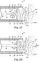
- the catheter body distal end 22 is atraumatic in order to be navigable through various bodily passages to an injection site 500 ( Figure 2C ).
- the fixation structure 30 may include portions configured as a helix designed to be affixed to tissue 520 generally proximate the injection site 500 by being screwed into the tissue 520 ( Figure 2 ).
- the catheter body proximal end 28 is secured to handle 410, which allows the physician to manipulate the catheter body 20 in order to direct the catheter body distal end 22 to the injection site 500.
- a drive shaft 40 may engage a driver knob 420, which is rotatably secured to the handle 410.
- the drive shaft 40 cooperates with the fixation structure 30 and with the driver knob 420 to allow the physician to screw the fixation structure 30 into the tissue 520 by rotation of the driver knob 420 to a fixation depth 180.
- various gears and other mechanical features as would be recognized by those of ordinary skill in the art upon study of this disclosure may be provided about the handle 410 and/or about the catheter body 20 so that the fixation structure 30 may cooperate with the driver knob 420 via the drive shaft 40.
- One or more ports 430 may be placed about the handle 410 and/or the catheter body 20 generally proximate the catheter body proximal end 28.
- the ports 430 communicate with various lumens within the catheter body 20 to allow, for example, for the introduction/withdrawal of guidewire(s) and/or introduction of injectate.
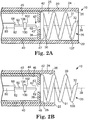
- Figures 2A to 2E show portions of the illustrative injector apparatus 10 at the catheter body distal end 22 in various operational conditions.
- the catheter body 20 defines a catheter body outer wall 24 and a catheter body inner wall 26, and a catheter body lumen 25 is defined by the catheter body inner wall 26.
- the drive shaft 40 defines a drive shaft outer wall 44 and a drive shaft inner wall 46, and a drive shaft lumen 45 is defined by the drive shaft inner wall 46.
- the drive shaft 40 is rotatably received within the catheter body lumen 25 to allow the physician to screw the fixation structure 30 into tissue 520 generally proximate the injection site 500.
- Portions of the drive shaft 40 may be biased against the catheter body inner wall 26, support structures may be placed along the length of the catheter body lumen 25 to support rotatably the drive shaft 40 within the catheter body lumen 25, and/or the drive shaft 40 may be otherwise mounted within the catheter body lumen 25 to be rotatable in ways readily recognizable by those of ordinary skill in the art upon study of this disclosure.
- a fixation structure proximal end 38 of the fixation structure 30 is secured to the drive shaft distal end 42 of the drive shaft 40.
- the drive shaft distal end 42 is positioned between at least a drive shaft first position 47 ( Figure 2A ) and a drive shaft second position 49 ( Figure 2B ) in order to position the fixation structure 30 between at least a first fixation structure position 137 and a second fixation structure position 139.
- the fixation structure 30 is in the first fixation structure position 137 wherein the fixation structure 30 is contained within the outer body lumen 25 generally proximate the catheter body distal end 22 in order to allow the catheter body distal end 22 to be advanced through bodily passages.
- the drive shaft 40 may cooperate with a stabilizer position control 442 in the handle 410 in various implementations.
- the driver knob 420 may be used as the stabilizer position control 442, so that pushing the driver knob 420 in the distal direction would position the drive shaft distal end 42 in the drive shaft second position 49 and pulling the driver knob 420 in the proximal direction would retract the drive shaft distal end 42 into the drive shaft first position 47 and correspondingly position the fixation structure 30 between the first fixation structure position 137 and the second fixation structure position 139.
- the fixation structure 30 illustratively includes a helix 31, the interior annular surface of which defines an internal passage 35 about axis 39.
- the fixation structure 30 including the helix 31 may be made of any suitable material, including metals such as a platinum iridium alloy.
- the fixation structure proximal end 38 may be secured to the drive shaft distal end 42 in any desired manner.
- a distal portion of the fixation structure 30 illustratively defines a fixation structure tip 32.
- the fixation structure tip 32 may be sharpened and/or otherwise configured to penetrate the tissue 520 as the fixation structure 30 is rotated in order to draw the fixation structure 30 into the tissue 520.
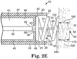
- the injector apparatus 10 includes an injector needle 60 that has an injector needle tip 62 and an injector needle proximal end 68.
- the position of the injector needle 60 relative to the catheter body distal end 22 may be varied between at least a first injector needle position 67 and a second injector needle position 69 ( Figure 2E ).
- the position of the injector needle 60 relative to the fixation structure 30 is varied as the injector needle 60 is alternated between the first injector needle position 67 and the second injector needle position 69.
- the injector needle tip 62 may be well proximal of the fixation structure tip 32 with the injector needle 60 in the first injector needle position 67, and near to the fixation structure tip 32 (even with or proximal of or distal of) with the injector needle 60 in the second injector needle position 69.
- the injector needle 60 may reside within the catheter body lumen 25, as illustrated in Figure 2A , with the injector needle tip 62 generally within the catheter body lumen 25 proximal of the catheter body distal end 22 and proximal of the fixation structure tip 32.
- the injector needle 60 in the first injector needle position 67 may be generally proximate the catheter body distal end 22 as illustrated in Figure 2A , wherein the injector needle 60 in the first injector needle position 67 is located within the drive shaft lumen 45.
- at least a portion of the injector needle 60 may reside within internal passage 35 of the fixation structure 30.
- the injector needle 60 may cooperate with an injector needle position control 444 in the handle 410 in various implementations.
- the injector needle position control 444 ( Figure 1 ) may be configured as a sliding button 446 on the handle 410 that slides generally in a proximal-distal orientation along the handle 410. Sliding the sliding button 446 in the distal direction positions the injector needle 60 in the injector needle second position 69, while sliding the sliding button 446 in the proximal direction retracts the injector needle 60 into the injector needle first position 67.
- the injector needle 60 has an injector needle lumen 65 ( Figure 3A ) in communication between an injector needle proximal end 68 and the injector needle tip 62 to communicate injectate from the injector needle proximal end 68 to the injector needle tip 62 for injection into tissue 520.
- the injector needle 60 may be made, for example, of steel or other metals or metal alloys.
- FIG 2B illustrates the drive shaft distal end 42 in the second position 49.
- the fixation structure 30 is correspondingly positioned in the second fixation structure position 139, in which at least a portion of the fixation structure 30 emerges from the catheter body lumen 25.
- the fixation structure 30 rotatably emerges from the catheter body lumen 25 so that the fixation structure tip 32 may penetrate tissue 520 proximate the injection site 500.
- the fixation structure tip 32 may be biased against the tissue 520 and the drive shaft 40 rotated to rotate the fixation structure 30 and screw the fixation structure 30 into the tissue 520 to the fixation depth 180 ( Figure 2D ).
- the fixation structure 30 may be alternated between the first fixation structure position 137 and the second fixation structure position 139 in other ways, as would be recognized by one of ordinary skill in the art upon study of this disclosure.
- the fixation structure 30 may be generally fixed in the second fixation structure position 139.
- Various implementations may omit the drive shaft 40, and the fixation structure 30 may be rotated by, for example, rotation of the catheter body 20 to draw the fixation structure 30 into the tissue 520 to the fixation depth 180.
- the fixation structure 30 may be rotated in other ways in order to penetrate into the tissue 520 to the fixation depth 180, as would be recognized by one of ordinary skill in the art upon study of this disclosure.
- fixation structure 30 penetrates into the tissue 520 to the fixation depth 180 sufficient to anchor the injector apparatus 10 to the tissue 520 proximate the injection site 500.
- the fixation structure 30 may penetrate into the tissue 520 until the catheter body distal end 22 is drawn into and biased against the tissue 520, or as shown in Figures 2C-2E , the fixation structure 30 may penetrate into the tissue 520 to a lesser degree such that the catheter body distal end 22 remains spaced away from the tissue 520. In either case, the catheter body distal end 22 is fixed with respect to the tissue 520.
- an injector needle 60 lies generally along the axis 39, and includes a stop 100 for limiting the penetration of the injector needle into the tissue 520.
- the stop 100 is illustrated as a disc of a size capable of passing through aperture 43 and through internal passage 35, although a variety of other shapes and sizes are suitable for the stop 100.
- the injector needle 60 moves relative to the fixation structure 30 as the injector needle is advanced from the injector needle first position 67.
- the injector needle 60 is advanced relative to the catheter body distal end 22 and relative to the fixation structure 30 to the second injector needle position 69 ( Figure 2E ) wherein the injector needle penetrates the myocardium until the stop engages the epicardium/endocardium.
- Figure 2E illustrates the injector needle 60 positioned in the second injector needle position 69 to penetrate into the tissue 520 to a penetration depth 170 regulated by the position of the stop 100 with respect to the injector needle tip 62.
- the distal face 102 of the stop 100 is biased against the epicardium/endocardium 540 to regulate the penetration depth 170 of the injector needle 60.
- the catheter body distal end 22 is fixed with respect to the tissue 520 (in a spaced away position as shown).
- the penetration depth 170 of the injector needle 60 may be equal to, less than, or greater than the fixation depth 180 of the fixation structure 30.
- the injector needle tip 62 is generally at the same depth as the fixation structure tip 32, but in other implementations may be distal of the fixation structure tip 32 or proximal of the fixation structure tip 32, as desired.
- the penetration depth 170 to which the injector needle 60 penetrates the tissue 520 is determined by the position of the stop 100 with respect to the injector needle tip 62, and is independent of the fixation depth 180 to which the fixation structure 30 penetrates the tissue 520.
- the injector needle 60 is in fluid communication with an injector catheter 80.
- the distal end of the injector catheter 80 and the injector needle proximal end 68 are proximal of the drive shaft distal end 42 and proximal of the aperture 43.
- the injector catheter 80 may extend through the aperture 43 such that the injector catheter distal end 82 may lie generally within the internal passage 35, and the injector needle proximal end 68 may be distal of the aperture 43 and may lie generally within the internal passage 35 of the helix 31.
- the injector needle 60 and the stop 100 are recessed behind the aperture 43.
- the injector needle 60 may extend into the internal passage 35 behind the catheter body distal end 22.
- the stop 100 may reside either behind or in front of the aperture 43. If the stop 100 need not pass through the aperture 43 during deployment of the injector needle 60, it may be larger than the aperture 43 provided it may still pass through the internal passage 35 of the helix 31.
- the stabilizer used in the illustrative implementation of Figures 2A-2E is a fixation structure, and more particularly, a fixation structure that includes portions configured as a helix 31 designed to penetrate tissue 520 generally proximate the injection site 500 by being screwed into the tissue 520, other types of fixation structures and more generally, other types of stabilizers may be used.
- a mechanical claw or a suction pad are alternatives.
- FIG. 3A A cut-away view of an illustrative implementation of the injector apparatus 10 is illustrated in Figure 3A and a transverse plan view is illustrated in Figure 3B .
- the proximal end 68 of the injector needle 60 is secured to the distal end 82 of the injector catheter 80 so that the injector needle lumen 65 is in communication with the injector catheter lumen 85.
- the injector needle 60 is generally aligned with axis 39.
- Stop 100 is illustrated as having a disc-shaped configuration sized to pass through the internal passage 35 defined by the fixation structure 30.
- an injector catheter 80 defines an injector catheter lumen 85, an injector catheter distal end 82, and an injector catheter proximal end (not shown).
- the injector catheter distal end 82 is secured to the injector needle proximal end 68 to communicate injectate into the injector needle lumen 65.
- the injector catheter lumen 85 generally at the injector catheter proximal end may communicate with port 430 on the handle 410 so that injectate may be communicated through port 430 into the injector catheter lumen 85, and thence through the injector needle lumen 65 into the tissue 520 at the injection site 500.
- a reservoir (not shown) may be located within the catheter body lumen 25 in communication with the injector catheter lumen 85 to communicate injectate into the injector catheter lumen 85, and thence into the injector needle lumen 65, and the injectate may be delivered upon receipt of a signal communicated from the handle 410 to the reservoir.
- the injector needle proximal end 68 may be located near the reservoir so that the reservoir may communicate substantially directly with the injector lumen 65.
- the injector catheter lumen 85 may be a dual lumen (two lumen arranged side-by-side or coaxially) which communicate with respective ports on the handle 410. The components may mix before passing into the injector catheter lumen 85, or may pass into respective lumen within the injector needle 60 and mix within the tissue 520 after injection therein.
- the stop 100 extends circumferentially about a portion of the injector needle 60 to limit the penetration of the injector needle 60 into the tissue 520.
- the stop 100 has a distal face 102 and a proximal face 108.
- the stop 100 is sized to pass through the aperture 43 and internal passage 35.
- the injector needle 60 and the stop 100 pass through the aperture 43 defined by the drive shaft distal end 42 of the drive shaft 40, and through the internal passage 35 defined by the helix 31 and generally along the axis 39.
- the distal face 102 of the stop 100 is biased against the epicardium/endocardium 540 to establish the penetration depth 170 and to prevent further penetration of the injector needle 60 into the myocardial tissue 520.
- the stop 100 may be secured in any desired manner to the injector needle 60 at a specific location with respect to the injector needle tip 62, and the location may be fixed or variable. Fixation may be achieved in any desired manner, such as, for example, by welding or gluing. Moreover, the stop 100 may be implemented by a thickened region of the injector needle itself. In implementations having a variably positionable stop, the stop may be secured to the injector needle 60 by, for example, a set screw or set nut (not shown) to allow adjustment of the location of the stop with respect to the injector needle tip 62.
- Figure 3B illustrates the injector needle 60 generally aligned with axis 39 to allow the stop 100 to pass through the aperture 43 and through the internal passage 35.
- the stop 100 as illustrated, is sized to pass through the internal passage 35.
- injector catheter lumen 85 may be implemented in other ways.
- An illustrative alternative implementation is as a bore through a core of the catheter body, with a deployment mechanism for the injector needle 60 being provided within the drive shaft distal end 42.
- the stop 100 may be made in a variety of different shapes, including, for example, generally disc-shaped, generally spherical, generally ellipsoidal, generally oblate spheroidal, or any other shape that is suitable for passing through the internal passage 35 without being entrapped by the helix 31, and that is effective for limiting, the penetration of the injector needle 60 into the tissue 520.
- Figure 4 shows an alternative illustrative implementation of an injector needle 260 that includes a stop 280 and injection ports 165. The injection ports 165 are located along the injector needle 260 between the injector needle tip 262 and the stop 280.
- Injectate may be introduced into the tissue 520 through the injection ports 165 as well as through the injector needle tip 262 in order to disperse injectate into the tissue 520 generally throughout the penetration depth 170.
- the stop 280 as illustrated, has a generally spherical shape, to facilitate passage of the stop 280 through the internal passage 35 without being caught on portions of the helix 31.
- An illustrative method of administering an injection into the myocardial tissue 520 through the epicardium using the injector apparatus 10 is as follows.
- the catheter body 10 is inserted into the thoracic cavity with the fixation structure 30 in a first fixation structure position 137 contained within the catheter body lumen 25.
- the catheter body distal end 22 is navigated through the thoracic cavity and through an opening in the pericardial sac until generally proximate the injection site 500 on the epicardium 540.
- the fixation structure 30 is deployed from the first fixation structure position 137 to the second fixation structure position 139.
- the fixation structure tip 32 is brought into engagement with the epicardium 540, and then the fixation structure 30 is rotated so that the fixation structure 30 penetrates into the tissue 520.
- the fixation structure proximal end 38 of the fixation structure 30 is engaged with the drive shaft 40 so that the fixation structure 30 is rotated by rotation of the drive shaft 40.
- the fixation structure 30 is rotated until the fixation structure penetrates into the tissue 520 in an amount sufficient to secure the catheter body distal end 22 to the tissue 520.
- the injector needle 60 is advanced from the first injector needle position 67 to the second injector needle position 69, so that the injector needle 60 penetrates the tissue 520 to the penetration depth 710 from the injector needle tip 62 to the stop 100.
- the injectate is then delivered into the tissue 520 through the injector needle 60.
- the injector needle 60 is retracted to the first injector needle position 67 in order to withdraw the injector needle 60 from the tissue 520.
- the fixation structure 30 is then rotated to withdraw the fixation structure 30 from the tissue 520, and the fixation structure 30 is then retracted from the second fixation structure position 139 to the first fixation structure position 137.
- the catheter body 20 is then withdrawn from the thoracic cavity.
- the catheter body distal end 22 may be redeployed generally proximate another injection site 500 along the epicardium 540 to deliver an injection of injectate at that injection site 500.
- these operations or combinations or subcombinations thereof may be repeated. Repeatedly redeploying the catheter over a number of injection sites 500 delivers a number of injections of injectate at a number of injection sites 500 along the epicardium 540.
- Various controls may be arranged about the handle 410 and/or other portions of the injector apparatus 10 to aid the physician in directing the catheter body distal end 22 to the epicardium/endocardium 540, to position the fixation structure 30 between the first fixation structure position 137 and the second fixation structure position 139, to position the injector needle between the first injector needle position 167 and the second injector needle position 169, and to cause the injectate to be delivered to the tissue 520 through the injector needle 60.
- Suitable controls would be known to one of ordinary skill in the art upon study of this disclosure.
Landscapes
- Health & Medical Sciences (AREA)
- Life Sciences & Earth Sciences (AREA)
- Public Health (AREA)
- Veterinary Medicine (AREA)
- Biomedical Technology (AREA)
- Heart & Thoracic Surgery (AREA)
- General Health & Medical Sciences (AREA)
- Engineering & Computer Science (AREA)
- Animal Behavior & Ethology (AREA)
- Hematology (AREA)
- Anesthesiology (AREA)
- Vascular Medicine (AREA)
- Surgery (AREA)
- Biophysics (AREA)
- Pulmonology (AREA)
- Pathology (AREA)
- Nuclear Medicine, Radiotherapy & Molecular Imaging (AREA)
- Medical Informatics (AREA)
- Molecular Biology (AREA)
- Infusion, Injection, And Reservoir Apparatuses (AREA)
Applications Claiming Priority (2)
| Application Number | Priority Date | Filing Date | Title |
|---|---|---|---|
| US12366108P | 2008-04-10 | 2008-04-10 | |
| PCT/US2009/002269 WO2009126323A1 (en) | 2008-04-10 | 2009-04-10 | Apparatus and method for controlled depth of injection into myocardial tissue |
Publications (2)
| Publication Number | Publication Date |
|---|---|
| EP2282798A1 EP2282798A1 (en) | 2011-02-16 |
| EP2282798B1 true EP2282798B1 (en) | 2016-12-14 |
Family
ID=40651731
Family Applications (1)
| Application Number | Title | Priority Date | Filing Date |
|---|---|---|---|
| EP09730816.7A Not-in-force EP2282798B1 (en) | 2008-04-10 | 2009-04-10 | Apparatus for controlled depth of injection into myocardial tissue |
Country Status (7)
| Country | Link |
|---|---|
| US (2) | US8801665B2 (enExample) |
| EP (1) | EP2282798B1 (enExample) |
| JP (1) | JP5780950B2 (enExample) |
| AU (1) | AU2009234312B2 (enExample) |
| CA (1) | CA2719912A1 (enExample) |
| ES (1) | ES2609678T3 (enExample) |
| WO (1) | WO2009126323A1 (enExample) |
Families Citing this family (33)
| Publication number | Priority date | Publication date | Assignee | Title |
|---|---|---|---|---|
| US8801665B2 (en) | 2008-04-10 | 2014-08-12 | Henry Ford Health System | Apparatus and method for controlled depth of injection into myocardial tissue |
| US8623395B2 (en) | 2010-01-29 | 2014-01-07 | Forsight Vision4, Inc. | Implantable therapeutic device |
| CA3045436C (en) | 2009-01-29 | 2025-10-07 | Forsight Vision4 Inc | Posterior segment drug delivery |
| US10166142B2 (en) | 2010-01-29 | 2019-01-01 | Forsight Vision4, Inc. | Small molecule delivery with implantable therapeutic device |
| HUE054113T2 (hu) | 2010-08-05 | 2021-08-30 | Forsight Vision4 Inc | Injekciós készülék gyógyszerbejuttatáshoz |
| CN103153316B (zh) | 2010-08-05 | 2015-08-19 | 弗赛特影像4股份有限公司 | 组合药物递送方法和设备 |
| HUE057267T2 (hu) | 2010-08-05 | 2022-05-28 | Forsight Vision4 Inc | Berendezés szem kezelésére |
| JP5683867B2 (ja) * | 2010-08-11 | 2015-03-11 | オリンパス株式会社 | 処置具 |
| EP2640360A2 (en) | 2010-11-19 | 2013-09-25 | Forsight Vision4, Inc. | Therapeutic agent formulations for implanted devices |
| US10398592B2 (en) | 2011-06-28 | 2019-09-03 | Forsight Vision4, Inc. | Diagnostic methods and apparatus |
| WO2013027107A1 (en) * | 2011-08-23 | 2013-02-28 | Simcha Milo | Device for creating temporary access and then closure |
| SI2755600T1 (sl) | 2011-09-16 | 2021-08-31 | Forsight Vision4, Inc. | Naprava za izmenjavo tekočine |
| EP2674109A1 (en) * | 2012-06-15 | 2013-12-18 | Endo Tools Therapeutics S.A. | Endoscopic surgical apparatus |
| JP5977601B2 (ja) * | 2012-06-27 | 2016-08-24 | オリンパス株式会社 | 医療用シース |
| AU2014236455B2 (en) | 2013-03-14 | 2018-07-12 | Forsight Vision4, Inc. | Systems for sustained intraocular delivery of low solubility compounds from a port delivery system implant |
| ES2972168T3 (es) | 2013-03-28 | 2024-06-11 | Forsight Vision4 Inc | Implante oftálmico para administración de sustancias terapéuticas |
| EP2991560B1 (en) | 2013-04-30 | 2020-07-29 | Cedars-Sinai Medical Center | Stabilization apparatuses for medical procedures |
| US20150005740A1 (en) * | 2013-06-28 | 2015-01-01 | Boston Scientific Scimed, Inc. | Injection devices and related methods of use |
| CA2957548A1 (en) | 2014-08-08 | 2016-02-11 | Forsight Vision4, Inc. | Stable and soluble formulations of receptor tyrosine kinase inhibitors, and methods of preparation thereof |
| WO2016069936A1 (en) * | 2014-10-29 | 2016-05-06 | Cedars-Sinai Medical Center | Apparatuses, systems and methods for controlled delivery of therapeutics and related substances |
| US10806922B2 (en) * | 2015-02-12 | 2020-10-20 | Medtronic, Inc | Medical access tools, assemblies, and methods |
| JP6912475B2 (ja) | 2015-11-20 | 2021-08-04 | フォーサイト・ビジョン フォー・インコーポレーテッドForsight Vision4, Inc. | 持続放出性薬物送達機器用の多孔質構造体 |
| JP6719545B2 (ja) * | 2016-03-11 | 2020-07-08 | テルモ株式会社 | 薬剤注入カテーテルおよび薬剤注入システム |
| WO2017155083A1 (ja) * | 2016-03-11 | 2017-09-14 | テルモ株式会社 | 薬剤注入カテーテルおよび薬剤注入システム |
| CN115607358A (zh) | 2017-11-21 | 2023-01-17 | 弗赛特影像4股份有限公司 | 用于可扩展端口递送系统的流体交换装置及使用方法 |
| US10980523B1 (en) * | 2019-11-01 | 2021-04-20 | Stephanie Toy | Medical device to access pericardial space with control |
| CN114159646B (zh) * | 2020-09-11 | 2025-09-02 | 宁波迪创医疗科技有限公司 | 一种心肌填充系统 |
| CN114681019B (zh) * | 2020-12-30 | 2024-07-02 | 杭州德晋医疗科技有限公司 | 一种心内膜注射装置及心内膜注射系统 |
| WO2022142663A1 (en) * | 2020-12-30 | 2022-07-07 | Hangzhou Valgen Medtech Co., Ltd. | Endocardial injection device and endocardial injection system |
| CN112870494B (zh) * | 2021-02-05 | 2021-12-28 | 普昂(杭州)医疗科技股份有限公司 | 一种注射深度可调节胰岛素用针头 |
| EP4205799B1 (fr) * | 2021-12-29 | 2024-02-14 | Cairdac | Dispositif médical implantable à vis d'ancrage hélicoïdale non traumatique |
| USD1033637S1 (en) | 2022-01-24 | 2024-07-02 | Forsight Vision4, Inc. | Fluid exchange device |
| WO2025052856A1 (ja) * | 2023-09-07 | 2025-03-13 | 株式会社カネカ | 穿刺針、穿刺針を備えた穿刺カテーテル、および、穿刺カテーテルを備えたカテーテルシステム |
Family Cites Families (64)
| Publication number | Priority date | Publication date | Assignee | Title |
|---|---|---|---|---|
| JPS5731Y2 (enExample) * | 1977-12-02 | 1982-01-05 | ||
| JPS60160808A (ja) | 1984-01-30 | 1985-08-22 | 佐伯 行 | 肥料散布機 |
| JPS60160808U (ja) * | 1984-04-05 | 1985-10-25 | オリンパス光学工業株式会社 | 内視鏡用処置具 |
| JP2531186B2 (ja) | 1987-07-16 | 1996-09-04 | 大同特殊鋼株式会社 | 超電導粉末の回収方法 |
| JPH04808Y2 (enExample) * | 1987-07-30 | 1992-01-13 | ||
| US5002067A (en) * | 1989-08-23 | 1991-03-26 | Medtronic, Inc. | Medical electrical lead employing improved penetrating electrode |
| US5324325A (en) * | 1991-06-27 | 1994-06-28 | Siemens Pacesetter, Inc. | Myocardial steroid releasing lead |
| US5447533A (en) * | 1992-09-03 | 1995-09-05 | Pacesetter, Inc. | Implantable stimulation lead having an advanceable therapeutic drug delivery system |
| WO1995003843A1 (en) * | 1993-07-30 | 1995-02-09 | The Regents Of The University Of California | Endocardial infusion catheter |
| US5431649A (en) * | 1993-08-27 | 1995-07-11 | Medtronic, Inc. | Method and apparatus for R-F ablation |
| DE4408108A1 (de) * | 1994-03-10 | 1995-09-14 | Bavaria Med Tech | Katheter zur Injektion eines Fluid bzw. eines Arneimittelns |
| US5551427A (en) * | 1995-02-13 | 1996-09-03 | Altman; Peter A. | Implantable device for the effective elimination of cardiac arrhythmogenic sites |
| US6322548B1 (en) * | 1995-05-10 | 2001-11-27 | Eclipse Surgical Technologies | Delivery catheter system for heart chamber |
| US6132451A (en) * | 1995-06-07 | 2000-10-17 | Eclipse Surgical Technologies, Inc. | Optical fiber for myocardial channel formation |
| US6283951B1 (en) * | 1996-10-11 | 2001-09-04 | Transvascular, Inc. | Systems and methods for delivering drugs to selected locations within the body |
| US6063061A (en) * | 1996-08-27 | 2000-05-16 | Fusion Medical Technologies, Inc. | Fragmented polymeric compositions and methods for their use |
| US6406420B1 (en) * | 1997-01-02 | 2002-06-18 | Myocor, Inc. | Methods and devices for improving cardiac function in hearts |
| US6045565A (en) * | 1997-11-04 | 2000-04-04 | Scimed Life Systems, Inc. | Percutaneous myocardial revascularization growth factor mediums and method |
| US6416510B1 (en) | 1997-03-13 | 2002-07-09 | Biocardia, Inc. | Drug delivery catheters that attach to tissue and methods for their use |
| US6511477B2 (en) * | 1997-03-13 | 2003-01-28 | Biocardia, Inc. | Method of drug delivery to interstitial regions of the myocardium |
| US6086582A (en) * | 1997-03-13 | 2000-07-11 | Altman; Peter A. | Cardiac drug delivery system |
| US5972013A (en) | 1997-09-19 | 1999-10-26 | Comedicus Incorporated | Direct pericardial access device with deflecting mechanism and method |
| JP3345317B2 (ja) | 1997-10-09 | 2002-11-18 | 旭光学工業株式会社 | 内視鏡用注射具 |
| US7031775B2 (en) * | 1997-11-07 | 2006-04-18 | Medtronic, Inc. | Method and system for myocardial infarction repair |
| DE69838526T2 (de) * | 1998-02-05 | 2008-07-03 | Biosense Webster, Inc., Diamond Bar | Gerät zum Freisetzen eines Medikaments im Herzen |
| US6547821B1 (en) * | 1998-07-16 | 2003-04-15 | Cardiothoracic Systems, Inc. | Surgical procedures and devices for increasing cardiac output of the heart |
| JP4118399B2 (ja) | 1998-07-21 | 2008-07-16 | テルモ株式会社 | 注射針用穿刺調整具およびそれを備えた注射針組立体 |
| US6360749B1 (en) * | 1998-10-09 | 2002-03-26 | Swaminathan Jayaraman | Modification of properties and geometry of heart tissue to influence heart function |
| US6685627B2 (en) | 1998-10-09 | 2004-02-03 | Swaminathan Jayaraman | Modification of properties and geometry of heart tissue to influence heart function |
| AU2707500A (en) * | 1998-12-04 | 2000-06-26 | Incept Llc | Biocompatible crosslinked polymers |
| US6689103B1 (en) * | 1999-05-07 | 2004-02-10 | Scimed Life System, Inc. | Injection array apparatus and method |
| US6709427B1 (en) | 1999-08-05 | 2004-03-23 | Kensey Nash Corporation | Systems and methods for delivering agents into targeted tissue of a living being |
| US6447443B1 (en) * | 2001-01-13 | 2002-09-10 | Medtronic, Inc. | Method for organ positioning and stabilization |
| US6508824B1 (en) * | 2000-02-18 | 2003-01-21 | Transvascular, Inc. | Catheter-based methods for enlarging blood vessels to facilitate the formation of penetration tracts, fistulas and/or blood flow channels |
| US6537198B1 (en) * | 2000-03-21 | 2003-03-25 | Myocor, Inc. | Splint assembly for improving cardiac function in hearts, and method for implanting the splint assembly |
| US6585716B2 (en) * | 2000-04-05 | 2003-07-01 | Biocardia, Inc. | Method of treating the heart |
| EP1301228B1 (en) * | 2000-07-13 | 2008-07-23 | Abbott Cardiovascular Systems Inc. | Deployment system for myocardial cellular material |
| US6493591B1 (en) * | 2000-07-19 | 2002-12-10 | Medtronic, Inc. | Implantable active fixation lead with guidewire tip |
| WO2002024248A1 (en) | 2000-09-22 | 2002-03-28 | Kensey Nash Corporation | Systems and methods for delivering beneficial agents into targeted tissue of a living being |
| US20020077687A1 (en) * | 2000-12-14 | 2002-06-20 | Ahn Samuel S. | Catheter assembly for treating ischemic tissue |
| US6620095B2 (en) * | 2000-12-22 | 2003-09-16 | Syde A. Taheri | Cradle-assisted myocardial repair and treatment |
| US7740623B2 (en) * | 2001-01-13 | 2010-06-22 | Medtronic, Inc. | Devices and methods for interstitial injection of biologic agents into tissue |
| US20020188170A1 (en) * | 2001-04-27 | 2002-12-12 | Santamore William P. | Prevention of myocardial infarction induced ventricular expansion and remodeling |
| US7311731B2 (en) * | 2001-04-27 | 2007-12-25 | Richard C. Satterfield | Prevention of myocardial infarction induced ventricular expansion and remodeling |
| CA2821193C (en) | 2001-04-27 | 2015-09-08 | Satterfield, Richard C. | Prevention of myocardial infarction induced ventricular expansion and remodeling |
| EP1412023A4 (en) * | 2001-07-16 | 2009-12-02 | Corassist Cardiovascular Ltd | METHOD AND DEVICE IN-VIVO FOR IMPROVING THE DIASTOLIC FUNCTION OF THE LEFT VENTRICLE |
| US20050177180A1 (en) | 2001-11-28 | 2005-08-11 | Aptus Endosystems, Inc. | Devices, systems, and methods for supporting tissue and/or structures within a hollow body organ |
| US20040106896A1 (en) | 2002-11-29 | 2004-06-03 | The Regents Of The University Of California | System and method for forming a non-ablative cardiac conduction block |
| AU2003239418B2 (en) | 2002-05-08 | 2008-01-31 | The Regents Of The University Of California | System and method for forming a non-ablative cardiac conduction block |
| CA2487254A1 (en) * | 2002-05-08 | 2003-11-20 | The Regents Of The University Of California | System and method for treating cardiac arrhythmias with fibroblast cells |
| US7103418B2 (en) * | 2002-10-02 | 2006-09-05 | Medtronic, Inc. | Active fluid delivery catheter |
| US8383158B2 (en) * | 2003-04-15 | 2013-02-26 | Abbott Cardiovascular Systems Inc. | Methods and compositions to treat myocardial conditions |
| MXPA05011896A (es) * | 2003-05-05 | 2006-05-25 | Univ Ben Gurion | Preparaciones polimericas reticuladas inyectables y sus usos. |
| JP2008509754A (ja) | 2004-08-12 | 2008-04-03 | ハンセン メディカル,インク. | ロボット制御脈管内組織注入システム |
| US20070172472A1 (en) * | 2005-06-23 | 2007-07-26 | Asha Nayak | Methods and Systems for Treating Injured Cardiac Tissue |
| WO2007002554A2 (en) * | 2005-06-23 | 2007-01-04 | Medtronic Vascular, Inc. | Methods and systems for treating injured cardiac tissue |
| US20070093748A1 (en) * | 2005-06-23 | 2007-04-26 | Medtronic Vascular, Inc. | Methods and systems for treating injured cardiac tissue |
| US20070028052A1 (en) * | 2005-07-28 | 2007-02-01 | International Business Machines Corporation | Method and apparatus for maintaining cached state data for one or more shared devices in a logically partitioned computer system |
| US7844348B2 (en) | 2005-08-09 | 2010-11-30 | Greatbatch Ltd. | Fiber optic assisted medical lead |
| US20070100199A1 (en) | 2005-11-03 | 2007-05-03 | Lilip Lau | Apparatus and method of delivering biomaterial to the heart |
| EP2032149A4 (en) * | 2006-06-13 | 2010-09-01 | Fmc Biopolymer As | METHOD AND SYSTEMS FOR THE USE OF BIOPOLYMER-BASED BEADS AND HYDROGELS |
| AU2007292923B2 (en) * | 2006-09-08 | 2013-10-03 | Cardiopolymers, Inc. | Intramyocardial patterning for global cardiac resizing and reshaping |
| WO2009119787A1 (ja) | 2008-03-28 | 2009-10-01 | テルモ株式会社 | 注射器 |
| US8801665B2 (en) | 2008-04-10 | 2014-08-12 | Henry Ford Health System | Apparatus and method for controlled depth of injection into myocardial tissue |
-
2009
- 2009-04-09 US US12/421,541 patent/US8801665B2/en active Active
- 2009-04-10 ES ES09730816.7T patent/ES2609678T3/es active Active
- 2009-04-10 JP JP2011504014A patent/JP5780950B2/ja not_active Expired - Fee Related
- 2009-04-10 CA CA2719912A patent/CA2719912A1/en not_active Abandoned
- 2009-04-10 AU AU2009234312A patent/AU2009234312B2/en not_active Ceased
- 2009-04-10 EP EP09730816.7A patent/EP2282798B1/en not_active Not-in-force
- 2009-04-10 WO PCT/US2009/002269 patent/WO2009126323A1/en not_active Ceased
-
2014
- 2014-07-17 US US14/333,891 patent/US20140330249A1/en not_active Abandoned
Also Published As
| Publication number | Publication date |
|---|---|
| ES2609678T3 (es) | 2017-04-21 |
| US8801665B2 (en) | 2014-08-12 |
| WO2009126323A1 (en) | 2009-10-15 |
| EP2282798A1 (en) | 2011-02-16 |
| JP2011516205A (ja) | 2011-05-26 |
| AU2009234312B2 (en) | 2014-09-04 |
| JP5780950B2 (ja) | 2015-09-16 |
| AU2009234312A1 (en) | 2009-10-15 |
| US20090259212A1 (en) | 2009-10-15 |
| CA2719912A1 (en) | 2009-10-15 |
| US20140330249A1 (en) | 2014-11-06 |
Similar Documents
| Publication | Publication Date | Title |
|---|---|---|
| EP2282798B1 (en) | Apparatus for controlled depth of injection into myocardial tissue | |
| JP2011516205A5 (enExample) | ||
| JP5698731B2 (ja) | 基質に治療薬剤を送達する注入カテーテル | |
| US7686799B2 (en) | Deployment system for myocardial cellular material | |
| EP2337605B1 (en) | Needle catheter with an angled distal tip lumen | |
| US7033345B2 (en) | Deflectable microimplant delivery system | |
| US20120239069A1 (en) | Transseptal Puncturing Device | |
| US20050273050A1 (en) | Balloon catheter and device for injecting medical treatment method | |
| US20070282267A1 (en) | Myocardial injector | |
| US20020029037A1 (en) | Method and apparatus for percutaneous trans-endocardial reperfusion | |
| EP2456484A2 (en) | Microneedle delivery device and methods of using same | |
| JP2008521569A (ja) | 心膜腔にアクセスする方法及びシステム | |
| US20160331406A1 (en) | Endoscopic Cannulas and Methods Of Using the Same | |
| CN110339433B (zh) | 一种用于超声引导下经胸经心外膜心肌内注射的三联穿刺针装置和方法 | |
| CN215129689U (zh) | 一种心内膜注射装置及心内膜注射系统 | |
| WO2010125159A1 (en) | Device for delivering a therapeutic agent | |
| WO1999049926A2 (en) | Delivery of an angiogenic substance | |
| US8308708B2 (en) | Deployment system for myocardial cellular material | |
| JP2003515383A (ja) | 組織に薬剤を送達するための方法および装置 | |
| WO2000025850A1 (en) | Medicinal agent administration catheter device | |
| CN211024568U (zh) | 一种三联穿刺针装置 | |
| WO2001010315A9 (en) | Gene therapy platformed needle and method of administering a therapeutic solution to a heart | |
| US20100047210A1 (en) | Systems and Methods for Positioning of Needles and Other Devices Within Body Tissue | |
| WO2023235260A1 (en) | Pericardial transection devices with plurality of incision members and methods of reducing pericardial restraint | |
| CN114727835A (zh) | 通过控制进入心包空间的医疗装置 |
Legal Events
| Date | Code | Title | Description |
|---|---|---|---|
| PUAI | Public reference made under article 153(3) epc to a published international application that has entered the european phase |
Free format text: ORIGINAL CODE: 0009012 |
|
| 17P | Request for examination filed |
Effective date: 20101028 |
|
| AK | Designated contracting states |
Kind code of ref document: A1 Designated state(s): AT BE BG CH CY CZ DE DK EE ES FI FR GB GR HR HU IE IS IT LI LT LU LV MC MK MT NL NO PL PT RO SE SI SK TR |
|
| AX | Request for extension of the european patent |
Extension state: AL BA RS |
|
| DAX | Request for extension of the european patent (deleted) | ||
| REG | Reference to a national code |
Ref country code: DE Ref legal event code: R079 Ref document number: 602009043057 Country of ref document: DE Free format text: PREVIOUS MAIN CLASS: A61M0025000000 Ipc: A61M0005158000 |
|
| GRAP | Despatch of communication of intention to grant a patent |
Free format text: ORIGINAL CODE: EPIDOSNIGR1 |
|
| RIC1 | Information provided on ipc code assigned before grant |
Ipc: A61M 5/34 20060101ALI20160126BHEP Ipc: A61M 5/158 20060101AFI20160126BHEP Ipc: A61B 17/34 20060101ALI20160126BHEP Ipc: A61M 25/00 20060101ALI20160126BHEP Ipc: A61M 5/46 20060101ALI20160126BHEP |
|
| INTG | Intention to grant announced |
Effective date: 20160212 |
|
| GRAP | Despatch of communication of intention to grant a patent |
Free format text: ORIGINAL CODE: EPIDOSNIGR1 |
|
| INTG | Intention to grant announced |
Effective date: 20160317 |
|
| GRAP | Despatch of communication of intention to grant a patent |
Free format text: ORIGINAL CODE: EPIDOSNIGR1 |
|
| INTG | Intention to grant announced |
Effective date: 20160601 |
|
| GRAS | Grant fee paid |
Free format text: ORIGINAL CODE: EPIDOSNIGR3 |
|
| GRAA | (expected) grant |
Free format text: ORIGINAL CODE: 0009210 |
|
| AK | Designated contracting states |
Kind code of ref document: B1 Designated state(s): AT BE BG CH CY CZ DE DK EE ES FI FR GB GR HR HU IE IS IT LI LT LU LV MC MK MT NL NO PL PT RO SE SI SK TR |
|
| REG | Reference to a national code |
Ref country code: GB Ref legal event code: FG4D |
|
| REG | Reference to a national code |
Ref country code: CH Ref legal event code: EP Ref country code: CH Ref legal event code: NV Representative=s name: BRAUNPAT BRAUN EDER AG, CH |
|
| REG | Reference to a national code |
Ref country code: SE Ref legal event code: TRGR |
|
| REG | Reference to a national code |
Ref country code: IE Ref legal event code: FG4D |
|
| REG | Reference to a national code |
Ref country code: AT Ref legal event code: REF Ref document number: 852998 Country of ref document: AT Kind code of ref document: T Effective date: 20170115 |
|
| REG | Reference to a national code |
Ref country code: DE Ref legal event code: R096 Ref document number: 602009043057 Country of ref document: DE |
|
| PG25 | Lapsed in a contracting state [announced via postgrant information from national office to epo] |
Ref country code: LV Free format text: LAPSE BECAUSE OF FAILURE TO SUBMIT A TRANSLATION OF THE DESCRIPTION OR TO PAY THE FEE WITHIN THE PRESCRIBED TIME-LIMIT Effective date: 20161214 |
|
| REG | Reference to a national code |
Ref country code: FR Ref legal event code: PLFP Year of fee payment: 9 |
|
| REG | Reference to a national code |
Ref country code: NL Ref legal event code: FP |
|
| REG | Reference to a national code |
Ref country code: LT Ref legal event code: MG4D |
|
| REG | Reference to a national code |
Ref country code: ES Ref legal event code: FG2A Ref document number: 2609678 Country of ref document: ES Kind code of ref document: T3 Effective date: 20170421 |
|
| PG25 | Lapsed in a contracting state [announced via postgrant information from national office to epo] |
Ref country code: NO Free format text: LAPSE BECAUSE OF FAILURE TO SUBMIT A TRANSLATION OF THE DESCRIPTION OR TO PAY THE FEE WITHIN THE PRESCRIBED TIME-LIMIT Effective date: 20170314 Ref country code: LT Free format text: LAPSE BECAUSE OF FAILURE TO SUBMIT A TRANSLATION OF THE DESCRIPTION OR TO PAY THE FEE WITHIN THE PRESCRIBED TIME-LIMIT Effective date: 20161214 Ref country code: GR Free format text: LAPSE BECAUSE OF FAILURE TO SUBMIT A TRANSLATION OF THE DESCRIPTION OR TO PAY THE FEE WITHIN THE PRESCRIBED TIME-LIMIT Effective date: 20170315 |
|
| PGFP | Annual fee paid to national office [announced via postgrant information from national office to epo] |
Ref country code: NL Payment date: 20170323 Year of fee payment: 9 |
|
| REG | Reference to a national code |
Ref country code: AT Ref legal event code: MK05 Ref document number: 852998 Country of ref document: AT Kind code of ref document: T Effective date: 20161214 |
|
| PG25 | Lapsed in a contracting state [announced via postgrant information from national office to epo] |
Ref country code: FI Free format text: LAPSE BECAUSE OF FAILURE TO SUBMIT A TRANSLATION OF THE DESCRIPTION OR TO PAY THE FEE WITHIN THE PRESCRIBED TIME-LIMIT Effective date: 20161214 Ref country code: HR Free format text: LAPSE BECAUSE OF FAILURE TO SUBMIT A TRANSLATION OF THE DESCRIPTION OR TO PAY THE FEE WITHIN THE PRESCRIBED TIME-LIMIT Effective date: 20161214 |
|
| PG25 | Lapsed in a contracting state [announced via postgrant information from national office to epo] |
Ref country code: EE Free format text: LAPSE BECAUSE OF FAILURE TO SUBMIT A TRANSLATION OF THE DESCRIPTION OR TO PAY THE FEE WITHIN THE PRESCRIBED TIME-LIMIT Effective date: 20161214 Ref country code: SK Free format text: LAPSE BECAUSE OF FAILURE TO SUBMIT A TRANSLATION OF THE DESCRIPTION OR TO PAY THE FEE WITHIN THE PRESCRIBED TIME-LIMIT Effective date: 20161214 Ref country code: CZ Free format text: LAPSE BECAUSE OF FAILURE TO SUBMIT A TRANSLATION OF THE DESCRIPTION OR TO PAY THE FEE WITHIN THE PRESCRIBED TIME-LIMIT Effective date: 20161214 Ref country code: IS Free format text: LAPSE BECAUSE OF FAILURE TO SUBMIT A TRANSLATION OF THE DESCRIPTION OR TO PAY THE FEE WITHIN THE PRESCRIBED TIME-LIMIT Effective date: 20170414 Ref country code: RO Free format text: LAPSE BECAUSE OF FAILURE TO SUBMIT A TRANSLATION OF THE DESCRIPTION OR TO PAY THE FEE WITHIN THE PRESCRIBED TIME-LIMIT Effective date: 20161214 |
|
| PGFP | Annual fee paid to national office [announced via postgrant information from national office to epo] |
Ref country code: CH Payment date: 20170427 Year of fee payment: 9 |
|
| PG25 | Lapsed in a contracting state [announced via postgrant information from national office to epo] |
Ref country code: BE Free format text: LAPSE BECAUSE OF FAILURE TO SUBMIT A TRANSLATION OF THE DESCRIPTION OR TO PAY THE FEE WITHIN THE PRESCRIBED TIME-LIMIT Effective date: 20161214 Ref country code: PT Free format text: LAPSE BECAUSE OF FAILURE TO SUBMIT A TRANSLATION OF THE DESCRIPTION OR TO PAY THE FEE WITHIN THE PRESCRIBED TIME-LIMIT Effective date: 20170414 Ref country code: AT Free format text: LAPSE BECAUSE OF FAILURE TO SUBMIT A TRANSLATION OF THE DESCRIPTION OR TO PAY THE FEE WITHIN THE PRESCRIBED TIME-LIMIT Effective date: 20161214 Ref country code: BG Free format text: LAPSE BECAUSE OF FAILURE TO SUBMIT A TRANSLATION OF THE DESCRIPTION OR TO PAY THE FEE WITHIN THE PRESCRIBED TIME-LIMIT Effective date: 20170314 Ref country code: PL Free format text: LAPSE BECAUSE OF FAILURE TO SUBMIT A TRANSLATION OF THE DESCRIPTION OR TO PAY THE FEE WITHIN THE PRESCRIBED TIME-LIMIT Effective date: 20161214 |
|
| PGFP | Annual fee paid to national office [announced via postgrant information from national office to epo] |
Ref country code: ES Payment date: 20170504 Year of fee payment: 9 Ref country code: SE Payment date: 20170403 Year of fee payment: 9 |
|
| REG | Reference to a national code |
Ref country code: DE Ref legal event code: R097 Ref document number: 602009043057 Country of ref document: DE |
|
| PLBE | No opposition filed within time limit |
Free format text: ORIGINAL CODE: 0009261 |
|
| STAA | Information on the status of an ep patent application or granted ep patent |
Free format text: STATUS: NO OPPOSITION FILED WITHIN TIME LIMIT |
|
| 26N | No opposition filed |
Effective date: 20170915 |
|
| PG25 | Lapsed in a contracting state [announced via postgrant information from national office to epo] |
Ref country code: DK Free format text: LAPSE BECAUSE OF FAILURE TO SUBMIT A TRANSLATION OF THE DESCRIPTION OR TO PAY THE FEE WITHIN THE PRESCRIBED TIME-LIMIT Effective date: 20161214 |
|
| REG | Reference to a national code |
Ref country code: IE Ref legal event code: MM4A |
|
| PG25 | Lapsed in a contracting state [announced via postgrant information from national office to epo] |
Ref country code: MC Free format text: LAPSE BECAUSE OF FAILURE TO SUBMIT A TRANSLATION OF THE DESCRIPTION OR TO PAY THE FEE WITHIN THE PRESCRIBED TIME-LIMIT Effective date: 20161214 |
|
| PG25 | Lapsed in a contracting state [announced via postgrant information from national office to epo] |
Ref country code: LU Free format text: LAPSE BECAUSE OF NON-PAYMENT OF DUE FEES Effective date: 20170410 Ref country code: SI Free format text: LAPSE BECAUSE OF FAILURE TO SUBMIT A TRANSLATION OF THE DESCRIPTION OR TO PAY THE FEE WITHIN THE PRESCRIBED TIME-LIMIT Effective date: 20161214 |
|
| PG25 | Lapsed in a contracting state [announced via postgrant information from national office to epo] |
Ref country code: IE Free format text: LAPSE BECAUSE OF NON-PAYMENT OF DUE FEES Effective date: 20170410 |
|
| REG | Reference to a national code |
Ref country code: CH Ref legal event code: PCAR Free format text: NEW ADDRESS: HOLEESTRASSE 87, 4054 BASEL (CH) |
|
| PG25 | Lapsed in a contracting state [announced via postgrant information from national office to epo] |
Ref country code: MT Free format text: LAPSE BECAUSE OF NON-PAYMENT OF DUE FEES Effective date: 20170410 |
|
| REG | Reference to a national code |
Ref country code: FR Ref legal event code: PLFP Year of fee payment: 10 |
|
| REG | Reference to a national code |
Ref country code: CH Ref legal event code: PL |
|
| REG | Reference to a national code |
Ref country code: SE Ref legal event code: EUG |
|
| REG | Reference to a national code |
Ref country code: NL Ref legal event code: MM Effective date: 20180501 |
|
| PG25 | Lapsed in a contracting state [announced via postgrant information from national office to epo] |
Ref country code: SE Free format text: LAPSE BECAUSE OF NON-PAYMENT OF DUE FEES Effective date: 20180411 Ref country code: NL Free format text: LAPSE BECAUSE OF NON-PAYMENT OF DUE FEES Effective date: 20180501 |
|
| PG25 | Lapsed in a contracting state [announced via postgrant information from national office to epo] |
Ref country code: LI Free format text: LAPSE BECAUSE OF NON-PAYMENT OF DUE FEES Effective date: 20180430 Ref country code: CH Free format text: LAPSE BECAUSE OF NON-PAYMENT OF DUE FEES Effective date: 20180430 |
|
| PG25 | Lapsed in a contracting state [announced via postgrant information from national office to epo] |
Ref country code: HU Free format text: LAPSE BECAUSE OF FAILURE TO SUBMIT A TRANSLATION OF THE DESCRIPTION OR TO PAY THE FEE WITHIN THE PRESCRIBED TIME-LIMIT; INVALID AB INITIO Effective date: 20090410 |
|
| REG | Reference to a national code |
Ref country code: ES Ref legal event code: FD2A Effective date: 20190912 |
|
| PG25 | Lapsed in a contracting state [announced via postgrant information from national office to epo] |
Ref country code: CY Free format text: LAPSE BECAUSE OF NON-PAYMENT OF DUE FEES Effective date: 20161214 Ref country code: ES Free format text: LAPSE BECAUSE OF NON-PAYMENT OF DUE FEES Effective date: 20180411 |
|
| PG25 | Lapsed in a contracting state [announced via postgrant information from national office to epo] |
Ref country code: MK Free format text: LAPSE BECAUSE OF FAILURE TO SUBMIT A TRANSLATION OF THE DESCRIPTION OR TO PAY THE FEE WITHIN THE PRESCRIBED TIME-LIMIT Effective date: 20161214 |
|
| PG25 | Lapsed in a contracting state [announced via postgrant information from national office to epo] |
Ref country code: TR Free format text: LAPSE BECAUSE OF FAILURE TO SUBMIT A TRANSLATION OF THE DESCRIPTION OR TO PAY THE FEE WITHIN THE PRESCRIBED TIME-LIMIT Effective date: 20161214 |
|
| PGFP | Annual fee paid to national office [announced via postgrant information from national office to epo] |
Ref country code: IT Payment date: 20220421 Year of fee payment: 14 Ref country code: DE Payment date: 20220427 Year of fee payment: 14 |
|
| PGFP | Annual fee paid to national office [announced via postgrant information from national office to epo] |
Ref country code: GB Payment date: 20230823 Year of fee payment: 15 |
|
| REG | Reference to a national code |
Ref country code: DE Ref legal event code: R119 Ref document number: 602009043057 Country of ref document: DE |
|
| PGFP | Annual fee paid to national office [announced via postgrant information from national office to epo] |
Ref country code: FR Payment date: 20230830 Year of fee payment: 15 |
|
| PG25 | Lapsed in a contracting state [announced via postgrant information from national office to epo] |
Ref country code: DE Free format text: LAPSE BECAUSE OF NON-PAYMENT OF DUE FEES Effective date: 20231103 |
|
| PG25 | Lapsed in a contracting state [announced via postgrant information from national office to epo] |
Ref country code: IT Free format text: LAPSE BECAUSE OF NON-PAYMENT OF DUE FEES Effective date: 20230410 |
|
| GBPC | Gb: european patent ceased through non-payment of renewal fee |
Effective date: 20240410 |
|
| PG25 | Lapsed in a contracting state [announced via postgrant information from national office to epo] |
Ref country code: GB Free format text: LAPSE BECAUSE OF NON-PAYMENT OF DUE FEES Effective date: 20240410 |
|
| PG25 | Lapsed in a contracting state [announced via postgrant information from national office to epo] |
Ref country code: FR Free format text: LAPSE BECAUSE OF NON-PAYMENT OF DUE FEES Effective date: 20240430 |
|
| PG25 | Lapsed in a contracting state [announced via postgrant information from national office to epo] |
Ref country code: GB Free format text: LAPSE BECAUSE OF NON-PAYMENT OF DUE FEES Effective date: 20240410 Ref country code: FR Free format text: LAPSE BECAUSE OF NON-PAYMENT OF DUE FEES Effective date: 20240430 |