EP2280347B1 - Information processing apparatus, control method of the information processing apparatus, and recording medium - Google Patents
Information processing apparatus, control method of the information processing apparatus, and recording medium Download PDFInfo
- Publication number
- EP2280347B1 EP2280347B1 EP10170498A EP10170498A EP2280347B1 EP 2280347 B1 EP2280347 B1 EP 2280347B1 EP 10170498 A EP10170498 A EP 10170498A EP 10170498 A EP10170498 A EP 10170498A EP 2280347 B1 EP2280347 B1 EP 2280347B1
- Authority
- EP
- European Patent Office
- Prior art keywords
- mirroring system
- rebuilding
- host computer
- rebuild
- mirroring
- Prior art date
- Legal status (The legal status is an assumption and is not a legal conclusion. Google has not performed a legal analysis and makes no representation as to the accuracy of the status listed.)
- Active
Links
- 230000010365 information processing Effects 0.000 title claims abstract description 10
- 238000000034 method Methods 0.000 title claims description 28
- 230000008569 process Effects 0.000 claims description 18
- 238000004590 computer program Methods 0.000 claims description 5
- 230000000717 retained effect Effects 0.000 claims description 2
- 230000006870 function Effects 0.000 description 10
- 230000004044 response Effects 0.000 description 8
- 230000008859 change Effects 0.000 description 4
- 230000002093 peripheral effect Effects 0.000 description 4
- 230000005540 biological transmission Effects 0.000 description 3
- 230000006837 decompression Effects 0.000 description 3
- 230000006835 compression Effects 0.000 description 2
- 238000007906 compression Methods 0.000 description 2
- 230000003111 delayed effect Effects 0.000 description 2
- 238000010586 diagram Methods 0.000 description 2
- 230000002035 prolonged effect Effects 0.000 description 2
- 238000006243 chemical reaction Methods 0.000 description 1
- 230000003247 decreasing effect Effects 0.000 description 1
- 238000012986 modification Methods 0.000 description 1
- 230000004048 modification Effects 0.000 description 1
Images


Classifications
-
- G—PHYSICS
- G06—COMPUTING; CALCULATING OR COUNTING
- G06F—ELECTRIC DIGITAL DATA PROCESSING
- G06F11/00—Error detection; Error correction; Monitoring
- G06F11/07—Responding to the occurrence of a fault, e.g. fault tolerance
- G06F11/16—Error detection or correction of the data by redundancy in hardware
- G06F11/20—Error detection or correction of the data by redundancy in hardware using active fault-masking, e.g. by switching out faulty elements or by switching in spare elements
- G06F11/2053—Error detection or correction of the data by redundancy in hardware using active fault-masking, e.g. by switching out faulty elements or by switching in spare elements where persistent mass storage functionality or persistent mass storage control functionality is redundant
- G06F11/2056—Error detection or correction of the data by redundancy in hardware using active fault-masking, e.g. by switching out faulty elements or by switching in spare elements where persistent mass storage functionality or persistent mass storage control functionality is redundant by mirroring
- G06F11/2082—Data synchronisation
-
- G—PHYSICS
- G06—COMPUTING; CALCULATING OR COUNTING
- G06F—ELECTRIC DIGITAL DATA PROCESSING
- G06F11/00—Error detection; Error correction; Monitoring
- G06F11/07—Responding to the occurrence of a fault, e.g. fault tolerance
- G06F11/08—Error detection or correction by redundancy in data representation, e.g. by using checking codes
- G06F11/10—Adding special bits or symbols to the coded information, e.g. parity check, casting out 9's or 11's
- G06F11/1076—Parity data used in redundant arrays of independent storages, e.g. in RAID systems
-
- G—PHYSICS
- G06—COMPUTING; CALCULATING OR COUNTING
- G06F—ELECTRIC DIGITAL DATA PROCESSING
- G06F11/00—Error detection; Error correction; Monitoring
- G06F11/07—Responding to the occurrence of a fault, e.g. fault tolerance
- G06F11/16—Error detection or correction of the data by redundancy in hardware
- G06F11/20—Error detection or correction of the data by redundancy in hardware using active fault-masking, e.g. by switching out faulty elements or by switching in spare elements
- G06F11/2053—Error detection or correction of the data by redundancy in hardware using active fault-masking, e.g. by switching out faulty elements or by switching in spare elements where persistent mass storage functionality or persistent mass storage control functionality is redundant
- G06F11/2056—Error detection or correction of the data by redundancy in hardware using active fault-masking, e.g. by switching out faulty elements or by switching in spare elements where persistent mass storage functionality or persistent mass storage control functionality is redundant by mirroring
- G06F11/2087—Error detection or correction of the data by redundancy in hardware using active fault-masking, e.g. by switching out faulty elements or by switching in spare elements where persistent mass storage functionality or persistent mass storage control functionality is redundant by mirroring with a common controller
Definitions
- the present invention relates to an information processing apparatus including a plurality of hard disks, a control method of the information processing apparatus, and a recording medium.
- a mirroring technique which records identical data in a plurality of local hard disks.
- an ongoing processing can be continued by using another hard disk, which improves reliability.
- a mirroring system which performs mirroring, is provided with a function to rebuild (build again) data.
- Rebuild is a function to recover data of a failed hard disk (HDD) from a remaining trouble-free HDD when a failure occurs in one of two HDDs. For example, rebuild is performed to achieve consistency between the operating HDD and a HDD mounted to replace the failed HDD.
- HDD hard disk
- the mirroring system further includes a so-called patrol function configured to correct errors by reading all sectors of the two HDDs and rewriting the sectors of the error-detected HDD by data from the other HDD.
- the mirroring system In the mirroring system provided with the functions described above, generally, while power to a host computer is discontinued or the host computer enters a sleep mode, power supply to the mirroring system is stopped and goes into a power-off state. When the power supply to the mirroring system turns off while the mirroring system is executing rebuild processing, information as to how far a rebuild processing has been executed is recorded in a non-volatile memory in the mirroring system.
- the mirroring system automatically resumes the rebuild processing, which has been interrupted, according to information stored in the non-volatile memory.
- Rebuild (or patrol) processing is usually executed for each predetermined number of blocks.
- HDD read/write request is sent from the host computer connected to the mirroring system during a rebuild processing
- HDD read/write operations requested by the host computer are executed in time slots between blocks of rebuild processing.
- Japanese Patent Application Laid-Open No. 2007-94994 discusses a technique in which when HDD access requests frequently come from a host computer, by recasting the blocks of rebuild processing into smaller units, the response to HDD access requests from the host computer can be made quicker.
- the response to HDD access requests from the host computer can be accelerated.
- the blocks of the rebuild processing are reduced into smaller units, the response speed remains unimproved compared to a case where the rebuild processing is not performed.
- the HDD is accessed frequently particularly when the host computer is started, because a boot program of the entire system is stored in the HDD. If the interrupted rebuild processing is resumed automatically, a problem arises that the start-up time of the system is prolonged.
- US 6 647 514 discloses that improved host I/O performance and availability of a storage array during rebuild is obtained by prioritizing I/O requests.
- US 2007/101187 discloses that read and write processing of a rebuild are simultaneously executed on a condition that a normal I/O request is absent for a predetermined time.
- US 2007/088976 discloses that a processing size for one time of Rebuild/Copy back is increased on a condition that a normal I/O request is absent for a predetermined time.
- a mirroring system as specified in claim 1.
- a control method for a mirroring system as specified in claim 7.
- a computer program according to claim 9. Such a computer program can be provided by itself or stored on a computer-readable storage medium as specified in claim 10, which regards a fourth aspect of the invention.
- the storage medium may be a recording or other storage medium.
- the storage medium may also be a transmission medium.
- the transmission medium may be a signal.
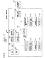
- Fig. 1 illustrates a system configuration provided to execute mirroring processing according to an exemplary embodiment of a present invention.
- Fig. 2 is a block diagram illustrating a hardware configuration of a multi-function peripheral (MFP) according to the exemplary embodiment.
- MFP multi-function peripheral
- Fig. 3 illustrates information to be stored in FLASH memory in a mirroring system according to the exemplary embodiment.
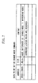
- Fig. 4 is a tabulated list of extended commands of Serial AT Attachment Interface (SATA) according to the exemplary embodiment.
- SATA Serial AT Attachment Interface
- Fig. 5 illustrates data to be sent from a host computer to the mirroring system according to the exemplary embodiment.
- Fig. 6 illustrates data to be sent from the host compute to the mirroring system according to the exemplary embodiment.
- Fig. 7 illustrates data to be sent from the host computer to the mirroring system according to the exemplary embodiment.
- Fig. 8 is a flowchart illustrating processing to be executed in the mirroring system according to the exemplary embodiment.
- Fig. 1 illustrates a system configuration provided to execute a mirroring processing in the exemplary embodiment of a present invention.
- a system in Fig. 1 is applied to a multi-function peripheral (MFP)
- MFP multi-function peripheral
- a host computer 200 is configured to control the entire MFP.
- a mirroring system 300 is connected to a host computer 200 via a Serial AT Attachment Interface (SATA) 203, and controls a mirroring processing, which will be described later.
- SATA Serial AT Attachment Interface
- the mirroring system 300 includes a mirroring system CPU 301, a mirroring system internal flash memory (non-volatile memory) 307, and a timer 308.
- the mirroring system 300 is connected to HDDs 302, 303 as mass-storage devices via SATA signal lines 304, 305, respectively.
- a power supply unit 101 supplies power to the host computer 200, and a power supply unit 102 supplies power to the mirroring system 300.
- the host computer 200 and the mirroring system 301 have separate power supplies.
- power supply to the host computer 200 is discontinued, power supply to the mirroring system 300 is also turned off.
- the host computer is in sleep (power saving) mode, power supply to the mirroring system 300 is turned off.
- the host computer 200 is supplied with power or when the host computer 200 returns from the sleep mode, power supply to the mirroring system 300 is turned on.
- Fig. 2 is a block diagram illustrating a hardware configuration of a multi-function peripheral (MFP) according to the exemplary embodiment of the present invention.
- MFP multi-function peripheral
- the host computer 200 includes a controller function to control the entire MFP.
- the host computer 200 is electrically connected to an operation unit 401, a scanner unit 402, and a printer unit 403, and is also connected to a LAN via a network interface 206 as a network interface to communicate image data or device information with personal computers or external devices.
- the CPU 201 (the system control CPU in Fig. 1 ) collectively controls access to various connected devices according to a control program stored in a ROM 253, and centrally controls various items of processing performed by the internal controller function.
- the RAM 252 is a system work memory used by the CPU 201 for its operation, and also serves as a memory for temporarily storing image data.
- This RAM 252 is formed by an SRAM (non-volatile memory) to retain stored data after power supply is turned off, and a DRAM (volatile memory) in which stored data is erased after power is turned off.
- the ROM 253 stores a boot program of the apparatus.
- a hard disk controller 202 is connected to the mirroring system 300.
- Hard disks 302, 303 illustrated in Fig. 1 and connected to the mirroring system 300 are configured to store system software and image data.
- An operation unit interface 205 connects the system bus 203 and the operation unit 401.
- the operation unit interface 205 receives image data from the system bus 203 and outputs it to the operation unit 401 to display, and also outputs information sent from the operation unit 401 onto the system bus 203.
- An image bus 220 which is a transmission channel to exchange image data, is formed by a Peripheral Component Interconnect (PCI) bus.
- An Image Bus Interface 218 is a bus bridge to connect the system bus 203 and the image bus 220, and converts data structure.
- a scanner image processing unit 212 corrects, processes, and edits image data received from a scanner unit 402 via a scanner interface 211.
- the scanner image processing unit 212 determines whether received image data is of a color document or a monochrome document, and of a character document or a photo document.
- a result of determination is attached to image data. Attached information is called image area data.
- a compression unit 213 receives image data, and divides it into blocks each including 32 X 32 pixels, and the image data having blocks is called tile data.
- An MFP in the exemplary embodiment executes a copy processing as follows.
- Image data read by the scanner unit 402 is sent to the scanner image processing unit 212 via the scanner interface 211.
- the compression unit 213 compresses the tile data.
- the compressed image data (tile data) is sent to the RAM 252 and stored. If need arises, this image data is sent to an image conversion unit 217 and subjected to image processing, and sent back to the RAM 252 and stored.
- Data read from the RAM 252 is written into a mirroring system 300.
- the mirroring system 300 writes received data in the connected HDDs 302 and 303. Then, data read from the HDD 302 connected to the mirroring system 300 is sent onto the bus 203
- the image data is sent from the bus 203 to a decompression unit 216.
- the decompression unit 216 decompresses this image data.
- the decompression unit 216 rasterizes the decompressed image data including a plurality of tile data. Rastrized image data is sent to a printer image processing unit 215.
- Image data processed in the printer image processing unit 215 is sent to the printer 403 via the printer interface 214, and printed in the printer 403.
- the flow of data during copy processing in the MFP has been described.
- the image data is passed through the HDDs of the mirroring system 300 because it is assumed that a need will arise to secure a work area where page replacement is performed, for example.
- the mirroring system 300 transmits an ATA command given from the host computer 200 to the connected HDD.
- the command is transmitted to both HDDs.
- a write command from the host computer 200 to the HDDs is sent to the mirroring system 300 via the HDD controller 202.
- the mirroring system 300 issues a write command to all connected HDDs.
- a read command (read request) from the host computer 200 to the HDD is sent to the mirroring system 300 via the HDD controller 202. Different from a case of a write command, the mirroring system 300 issues a read command only to one of a plurality of connected HDDs, normally, to the master one of the HDDs.
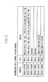
- Fig. 3 illustrates an example of information to be stored in the internal flash memory 307 of the mirroring system 300.
- a "rebuild delay time" is a value set by a SET REBUILD command, which will be described later. Even after the mirroring system has been started (initially or resumed after an interruption), until a designated number of seconds pass, the rebuild is not resumed (or commenced). If the user does not set this value, a default value is set. The rebuild delay time is set in seconds.
- a "patrol delay time” is a value set by a SET PATROL command, which will be described later. After the mirroring system has been started, until a designated number of seconds pass, the patrol is not resumed. If the user does not set this value, a default value is set. The patrol delay time is set in seconds.
- a "rebuild completed sector” is information indicating how far a rebuild has been completed. In other words, this information indicates, out of a plurality of sectors in the HDD, to which sector the rebuild has been completed.
- the mirroring system 300 interrupts the rebuild, and records an interrupted sector in the flash memory.
- the mirroring system 300 refers to the value of the rebuild completed sector, if the value is not 0, resumes the rebuild from the sector where the rebuild has been interrupted.
- a "patrol completed sector” is information indicating where the patrol has advanced. In other words, this information indicates, out of a plurality of sectors in the HDD, up to which sector the patrol has been completed.
- the mirroring system 300 interrupts the patrol, and records the sector where the patrol was interrupted.
- the mirroring system 300 refers to the value of the patrol completed sector, if this value is not 0, resumes the patrol from the patrol-interrupted sector.
- Fig. 4 is a table listing SATA extended commands. As described above, the mirroring system 300 can receive commands from the host computer via the SATA signal line. The mirroring system 300 in the present exemplary embodiment can receive extended commands in addition to ordinary SATA commands. Fig. 4 is a list of SATA extended commands used in the mirroring system in the present exemplary embodiment.
- the SATA commands are divided into "PIOOUT commands", "PIOIN commands", and "NONDATA” commands.
- the "PIOOUT” commands are commands to transfer data from the host computer to the mirroring system.
- the "PIOIN” commands are commands to transfer data from the mirroring system to the host computer.
- the "NONDATA” commands are commands not followed by data transfer.
- the extended commands sent from the host computer are interpreted only in the mirroring system 300, and are not sent to the HDDs 302, 303 via the SATA signal lines.
- the extended commands classified as the "PIOOUT” commands include "SETUP REBUILD", "SETUP PATROL”, AND "CHANGE MODE” commands.
- the "SETUP REBUILD” command is a command to set up a rebuild function.
- the "SETUP PATROL” command is a command to set up a patrol function.
- the "CHANGE MODE command” is a command to direct a changeover from the host computer to the mirroring system and from a single mode to a mirroring mode.
- the single mode is an operation mode in which only one HDD is used, and the single mode includes cases (1) only one HDD is connected to the mirroring system, and (2) one HDD is used out of a plurality of HDDs connected to the mirroring system.
- the mirroring mode is a mode in which a mirroring processing is executed.
- the extended commands classified into the "NONDATA” command category include the "TOSLEEP” and "WAKEUP" commands.
- the "TOSLEEP” command is a command to instruct that the power supply to the mirroring system should be turned off. This command is issued to the mirroring system when the host computer disconnects the power supply or enters the sleep mode.
- the mirroring system on receiving a "TOSLEEP” command, interrupts the rebuild or the patrol currently in progress, and records an interrupted sector in the flash memory. After this, the power supply to the mirroring system is turned off.
- the "WAKEUP" command is a command to notify the mirroring system of the host computer's return from the sleep mode.
- the power supply to the mirroring system is turned off either when the host computer turns off its power supply or when the host computer enters the sleep mode. Also, the power supply to the mirroring system is turned on either when the power supply to the host computer is turned on or the host computer returns from sleep.
- the mirroring system has no means to know whether the host computer has returned from the sleep mode or whether the power supply to the host computer has been turned on.
- this extended command "WAKEUP" is notified to the mirroring system. By this command, the mirroring system can know that the power supply to the mirroring system has been turned on because the host computer has been returned from sleep.
- the mirroring system can make a discrimination of whether the power is applied to the mirroring system because the power supply to the host computer has been turned on or because the host computer has returned from the sleep mode.
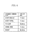
- Fig. 5 illustrates data sent from the host computer to the mirroring system when a "SETUP REBUILD" command as a "PIOOUT” command in Fig. 4 is executed. This data is generated by the host computer.
- the "rebuild delay time” indicates a wait time until a rebuild is executed after the mirroring system has been started. The mirroring system does not resume the rebuild until a designated number of seconds pass.
- the "whether or not to perform a rebuild” is information to indicate whether a rebuild is performed automatically when an error-detected hard disk is replaced.
- the "whether or not to verify data in a rebuild” is information to indicate whether data is verified when the mirroring system performs a rebuild.
- the "rebuild execution range” is information to specify whether the entire hard disk is rebuilt or only a specific range (sectors) is rebuilt when the mirroring system performs a rebuild.
- the "first sector and the size of area A" is information about a range set as a rebuild execution range
- Fig. 6 is a table of data sent from the host computer to the mirroring system when a "SETUP PATROL" command as a "PIOOUT” command in Fig. 4 is executed. This data is generated by the host computer.
- the "patrol delay time” indicates a wait time until patrol is performed after the mirroring system has been started.
- the mirroring system does not resume the rebuild until a designated number of seconds pass.
- the "start conditions” are information to indicate conditions for the mirroring system to start patrol.
- the "patrol execution range” is information about whether to patrol the entire hard disk or only a specified range (sectors) when the mirroring system performs patrol.
- the "first sector and the size of area A" is information about a range set as a patrol execution range
- Fig. 7 indicates data to be sent from the host computer to the mirroring system when a "CHANGE MODE” command as a "PIOOUT” command illustrated in Fig. 4 is executed. This data is generated by the host computer.
- the "CHANGE MODE” command is used to switch over between the single mode and the mirroring mode.
- a rebuild (or patrol) is performed by exchange of commands and data illustrated in Figs. 4 to 7 .
- data is read from the master HDD (HDD containing valid data) and written to a backup HDD (added HDD).
- a rebuild is a time-consuming work because a very large amount of data is rebuilt. While a rebuild is in progress, mirroring is not implemented, and user data is not protected by redundantly storing information on a spare disk. Therefore, it is desirable to complete a rebuild as quickly as possible.
- the above problem can also be said to arise in the case of patrol processing.
- the size of data to be read from the two HDDs can be adjusted indeed, but as patrol is performed, overhead is generated in issuance of commands to read and write data on the HDDs.
- Fig. 8 is a flowchart illustrating processing executed on the mirroring system 300 in the present exemplary embodiment. The steps of processing in Fig. 8 are executed by the mirroring system CPU 301 performing a computer program.
- step S801 the CPU 301 confirms that the HDDs are connected.
- step S802 the CPU 301 issues an identify command to each HDD, and conforms the condition of each connected HDD.
- step S803 the CPU 301 sets a transfer mode between the connection-confirmed HDD and the mirroring system.
- step S804 the CPU 301 determines whether mirroring should be performed. First, the CPU 301 determines whether the connections of the two HDDs are confirmed. When the two HDDs are confirmed as connected to the mirroring system, the CPU 301 determines whether consistency of data between the HDDs is achieved.
- the CPU 301 refers to information in the rebuild completed sector held in the internal flash memory 307 to determine whether the value is 0. If the value is 0, it is determined that the rebuild is completed, and it is also determined that consistency of data stored in the two HDDs is achieved.
- step S804 the CPU 301 determines two conditions of whether two HDDs are connected and whether the consistency of data in the two HDDs is achieved. If the two conditions are satisfied (YES in step S804), the processing proceeds to step S819. On the other hand, if at least one of the two conditions is not satisfied (NO in step S804), the processing proceeds to step S805.
- step S805 the CPU 301 determines whether a rebuild should be performed. In step S805, the number of the HDDs connected to the mirroring system 300 is confirmed, and if one HDD is connected, it is determined that a rebuild is not performed (NO in step S805), and the processing proceeds to step S 806.
- step S805 If the two HDDs are connected, the CPU 301 determines whether the single mode is currently set, and if the single mode is set, it is determined that a rebuild is not performed (NO in step S805), and the processing proceeds to step S806. On the other hand, if the two HDDs are connected and the value in the rebuild completed sector is other than 0, it is determined that a rebuild is performed (YES in step S805), the processing proceeds to step S807. In step S806, an ordinary operation is performed using one HDD.
- the mirroring system 300 As described above, if the value in the rebuild completed sector is other than 0, there is a rebuild interruption at this sector. More specifically, previously, the power supply to the mirroring system 300 was turned off by a "TOSLEEP" command issued from the host computer while the rebuild was being performed before the rebuild was completed. Therefore, the mirroring system, which has been started, needs to resume the rebuild from the sector where the rebuild was interrupted.
- step S807 the CPU 301 determines whether the power supply to the host computer 200 has been turned on from its power-off state or whether the host computer has returned from the sleep mode. More specifically, the CPU 301 determines whether the mirroring system 300 has received a "WAKEUP" command from the host computer 200. This is because the host computer 200, only when returning from sleep, issues a "WAKEUP" command to the mirroring system 300.
- step S807 when determining that the "WAKEUP" command has been received, the CPU 301 determines that the host computer 200 has returned from sleep (YES in step S807), and the processing proceeds to step S810. On the other hand, when determining that no "WAKEUP" command has been received, the CPU 301 determines that the power supply to the host computer 200 has been turned on from its power-off state, and the processing proceeds to step S808.
- step S808 the CPU 301 causes the timer 308 to start counting.
- step S809 the CPU 301 refers to the "rebuild delay time" stored in the internal flash memory 307, and determines whether the count of the timer 308 has reached the rebuild delay time. If the count of the timer 308 has reached the rebuild delay time (YES in step S809, the CPU 301 proceeds to step S810.
- step S810 the CPU 301 start a rebuild.
- the mirroring system 300 When the power supply to the host computer is turned on from its power-off state, it is necessary to wait for a delay time before the mirroring system 300 starts a rebuild. The reason is that after the power supply to the host computer 200 is turned on, the mirroring system 300 receives frequent accesses from the host computer 200 to read and write files.
- the response to requests from the host computer 200 to read and write the HDDs is slowed down.
- the mirroring system 300 starts a rebuild.
- the mirroring system 300 does not receive frequent accesses from the host computer to read and write files on the HDDs.
- the mirroring system 300 immediately starts a rebuild without waiting for a delay time to pass.
- step S811 the CPU 301 determines whether the mirroring system has received a "TOSLEEP" command from the host computer 200. If the CPU 301 has received "TOSLEEP” command, the processing proceeds to step S817. If the CPU 301 has not received "TOSLEEP” command, the processing proceeds to step S812.
- step S812 the CPU 301 reads data from the master HDD out of the two connected HDDs and, in step S813, writes data to the other (backup) HDD. Then, in step S314, the CPU 301 advances control from one sector to another for as many as the sectors of the backup HDD, on which data has been copied from the master HDD.
- step S815 the CPU 301 determines whether the rebuild of all the sectors has been completed. If the rebuild has been completed (YES in step S815), the processing proceeds to step S816. On the other hand, if the rebuild has not been completed (NO in step S815), the processing returns to step S811.
- step 816 the CPU 301 writes 0s in the rebuild completed sector in the internal flash memory 307. In other words, the CPU 301 writes information that the rebuild has been completed normally, and the processing proceeds to step S819, and from this step on, the CPU 301 performs mirroring.
- step S811 If it is determined in step S811 that a "TOSLEEP" command has been received from the host computer 200 (YES in step S811), the processing proceeds to step S817.
- step S817 the CPU 301 writes information that the rebuild has been interrupted in the rebuild completed sector, which is stored in the internal flash memory 307.
- the CPU 301 writes the sector, on which the rebuild has been performed, into the rebuild completed sector.
- step S818, the CPU 301 turns off the power supply.
- step S819 the CPU 301 performs a mirroring operation.
- the CPU 301 determines whether or not to perform patrol. Generally, the user designates an interval of patrol, such as once a month.
- the CPU 301 checks a condition for performing patrol, i.e., whether current time and date has reached a predetermined time and date.
- step S820 If patrol need not be performed (NO in step S820), the processing returns to step S819, and the mirroring operation is continued. If patrol needs to be performed (YES in step S820), in step S821, the CPU 301 performs a patrol operation, and when the patrol is completed (NO in step S820), the processing returns to step S819, and the mirroring operation is continued.
- step S821 when a patrol processing is performed, like in a rebuild, a determination similar to that performed in step S807 is performed.
- the host computer 200 returns from sleep, as in a rebuild, the similar processing as that performed in steps S808 and S809 is carried out. In other words, when the host computer 200 returns from sleep (or is turned on from its power-off state), the patrol processing is delayed for a period corresponding to a delay time.
- a rebuild is prevented from being resumed immediately when the rebuild processing in the mirroring system was interrupted by turning off the power supply to the host computer and the host computer has been started by turning on its power supply.
- This is intended to prevent a delay in HDD access from the host computer caused by a contention with the rebuild processing because access to the HDDs is requested frequently when the host computer is started.
- the rebuild is not resumed immediately, but after a lapse of a predetermined delay time, the rebuild is started. Therefore, a contention with many HDD accesses requested by the host computer can be prevented.
- the "rebuild delay time" retained in the flash memory 307 in the mirroring system may be changed arbitrarily by the user (administrator, for example).
- a startup time of the host computer may be calculated and the calculated startup time may be written automatically in the rebuild delay time.
- the mirroring system may be arranged to start a rebuild after receiving a notification that the startup has been completed from the host computer.
- the host computer and the mirroring system are included in one apparatus (MFP, for example), they can be provided as separate apparatuses.
- the present exemplary embodiment can be applied to a case where the host computer and the mirroring system are connected via a network, such as a LAN.
- aspects of the present invention can also be realized by a computer of a system or apparatus (or devices such as a CPU or MPU) that reads out and executes a program recorded on a memory device to perform the functions of the above-described embodiments, and by a method, the steps of which are performed by a computer of a system or apparatus by, for example, reading out and executing a program recorded on a memory device to perform the functions of the above-described embodiments.
- the program is provided to the computer for example via a network or from a recording medium of various types serving as the memory device (e.g., computer-readable medium) .
- the system or apparatus, and the recording medium where the program is stored are included as being within the scope of the present invention.
Landscapes
- Engineering & Computer Science (AREA)
- Theoretical Computer Science (AREA)
- Quality & Reliability (AREA)
- Physics & Mathematics (AREA)
- General Engineering & Computer Science (AREA)
- General Physics & Mathematics (AREA)
- Power Sources (AREA)
- Debugging And Monitoring (AREA)
- Facsimiles In General (AREA)
Applications Claiming Priority (1)
| Application Number | Priority Date | Filing Date | Title |
|---|---|---|---|
| JP2009172069A JP5409159B2 (ja) | 2009-07-23 | 2009-07-23 | 情報処理装置、情報処理装置の制御方法及びプログラム |
Publications (2)
| Publication Number | Publication Date |
|---|---|
| EP2280347A1 EP2280347A1 (en) | 2011-02-02 |
| EP2280347B1 true EP2280347B1 (en) | 2012-04-04 |
Family
ID=43034363
Family Applications (1)
| Application Number | Title | Priority Date | Filing Date |
|---|---|---|---|
| EP10170498A Active EP2280347B1 (en) | 2009-07-23 | 2010-07-22 | Information processing apparatus, control method of the information processing apparatus, and recording medium |
Country Status (6)
| Country | Link |
|---|---|
| US (2) | US8135983B2 (ko) |
| EP (1) | EP2280347B1 (ko) |
| JP (1) | JP5409159B2 (ko) |
| KR (1) | KR101311624B1 (ko) |
| CN (1) | CN101963926B (ko) |
| AT (1) | ATE552553T1 (ko) |
Families Citing this family (13)
| Publication number | Priority date | Publication date | Assignee | Title |
|---|---|---|---|---|
| JP5297479B2 (ja) * | 2011-02-14 | 2013-09-25 | エヌイーシーコンピュータテクノ株式会社 | ミラーリング復旧装置、および、ミラーリング復旧方法 |
| JP5398757B2 (ja) | 2011-02-14 | 2014-01-29 | 京セラドキュメントソリューションズ株式会社 | 給紙装置、及びこれを用いた画像形成装置 |
| JP5887757B2 (ja) * | 2011-08-17 | 2016-03-16 | 富士通株式会社 | ストレージシステム、ストレージ制御装置およびストレージ制御方法 |
| JP6032889B2 (ja) * | 2011-12-15 | 2016-11-30 | キヤノン株式会社 | 情報処理装置、制御方法、及びプログラム |
| US9430333B2 (en) * | 2013-03-14 | 2016-08-30 | Microsoft Technology Licensing, Llc | Recovery of application from snapshot |
| US10146623B2 (en) | 2013-11-18 | 2018-12-04 | Hewlett-Packard Development Company, L.P. | Indicating rebuild state of storage devices |
| JP6163137B2 (ja) * | 2014-06-03 | 2017-07-12 | 日本電信電話株式会社 | 信号制御装置及び信号制御方法 |
| JP6375936B2 (ja) * | 2014-12-24 | 2018-08-22 | コニカミノルタ株式会社 | 画像形成装置および画像形成装置の制御プログラム |
| JP6299617B2 (ja) * | 2015-01-27 | 2018-03-28 | コニカミノルタ株式会社 | 画像形成装置、画像形成装置の制御プログラム、コントローラー、およびコントローラーの制御プログラム |
| JP6700662B2 (ja) | 2015-02-10 | 2020-05-27 | キヤノン株式会社 | 情報処理装置、情報処理装置の制御方法、及びプログラム |
| JP7022605B2 (ja) * | 2018-01-26 | 2022-02-18 | キヤノン株式会社 | 情報処理装置とその制御方法、及びプログラム |
| CN112767412B (zh) * | 2020-12-31 | 2024-04-12 | 东软睿驰汽车技术(沈阳)有限公司 | 车辆部件级分割方法、装置以及电子设备 |
| CN113781500B (zh) * | 2021-09-10 | 2024-04-05 | 中国科学院自动化研究所 | 舱段图像实例分割的方法、装置、电子设备及存储介质 |
Family Cites Families (30)
| Publication number | Priority date | Publication date | Assignee | Title |
|---|---|---|---|---|
| US5802264A (en) * | 1991-11-15 | 1998-09-01 | Fujitsu Limited | Background data reconstruction in a storage device array system |
| US5483641A (en) * | 1991-12-17 | 1996-01-09 | Dell Usa, L.P. | System for scheduling readahead operations if new request is within a proximity of N last read requests wherein N is dependent on independent activities |
| US5313626A (en) * | 1991-12-17 | 1994-05-17 | Jones Craig S | Disk drive array with efficient background rebuilding |
| JP2888401B2 (ja) * | 1992-08-03 | 1999-05-10 | インターナショナル・ビジネス・マシーンズ・コーポレイション | 冗長ディスクドライブアレイに対する同期方法 |
| JPH0973372A (ja) * | 1995-09-07 | 1997-03-18 | Fujitsu Ltd | 記憶制御方法及び記憶制御装置 |
| JPH103360A (ja) * | 1996-06-14 | 1998-01-06 | Fujitsu Ltd | 二重化記憶管理装置 |
| US6185699B1 (en) * | 1998-01-05 | 2001-02-06 | International Business Machines Corporation | Method and apparatus providing system availability during DBMS restart recovery |
| JP2001222346A (ja) * | 2000-02-10 | 2001-08-17 | Toshiba Corp | コンピュータ、コンピュータシステム、および省電力制御方法 |
| US6647514B1 (en) * | 2000-03-23 | 2003-11-11 | Hewlett-Packard Development Company, L.P. | Host I/O performance and availability of a storage array during rebuild by prioritizing I/O request |
| EP1187058A3 (en) * | 2000-08-30 | 2003-01-02 | Seiko Epson Corporation | Printing apparatus, data storage medium, interface device, printer control method, and interface control method |
| US7890741B2 (en) * | 2000-12-01 | 2011-02-15 | O2Micro International Limited | Low power digital audio decoding/playing system for computing devices |
| JP2003196096A (ja) * | 2001-12-07 | 2003-07-11 | Internatl Business Mach Corp <Ibm> | コンピュータシステム、その起動制御方法及びプログラム |
| US7055058B2 (en) * | 2001-12-26 | 2006-05-30 | Boon Storage Technologies, Inc. | Self-healing log-structured RAID |
| JP2004063039A (ja) * | 2002-07-31 | 2004-02-26 | Sony Corp | ディスク情報処理装置及びその制御方法 |
| US7162625B2 (en) * | 2003-03-10 | 2007-01-09 | Dell Products L.P. | System and method for testing memory during boot operation idle periods |
| US7062673B2 (en) * | 2003-05-19 | 2006-06-13 | Hitachi Global Technologies | System and method for sparing in RAID-1 system |
| JP2004362444A (ja) * | 2003-06-06 | 2004-12-24 | I-O Data Device Inc | ストレージデバイス制御装置及びストレージデバイス切替方法 |
| US7085962B1 (en) * | 2003-09-08 | 2006-08-01 | Veritas Operating Corporation | Method and system for completing a backup job that was interrupted during a backup process |
| US7415488B1 (en) * | 2004-12-31 | 2008-08-19 | Symantec Operating Corporation | System and method for redundant storage consistency recovery |
| US7386745B2 (en) * | 2005-01-19 | 2008-06-10 | International Business Machines Corporation | Enabling a client device in a client device/data center environment to resume from a sleep state more quickly |
| US20070043968A1 (en) * | 2005-08-17 | 2007-02-22 | Inventec Corporation | Disk array rebuild disruption resumption handling method and system |
| JP4817783B2 (ja) * | 2005-09-30 | 2011-11-16 | 富士通株式会社 | Raidシステム及びそのリビルド/コピーバック処理方法 |
| JP4472617B2 (ja) * | 2005-10-28 | 2010-06-02 | 富士通株式会社 | Raidシステム、raidコントローラ及びそのリビルド/コピーバック処理方法 |
| JP4052330B2 (ja) * | 2005-11-30 | 2008-02-27 | 株式会社日立製作所 | 撮像装置 |
| US7721143B2 (en) * | 2005-12-06 | 2010-05-18 | Lsi Corporation | Method for reducing rebuild time on a RAID device |
| CN100437504C (zh) * | 2006-04-06 | 2008-11-26 | 英业达股份有限公司 | 硬盘数据备份系统及方法 |
| TWI327290B (en) * | 2006-10-03 | 2010-07-11 | Magic Pixel Inc | Electronic system with nand flash memory storing boot code and a highly reliable boot up method |
| JP2008197745A (ja) * | 2007-02-08 | 2008-08-28 | Hitachi Ltd | ストレージ仮想化システムにおける記憶制御装置 |
| US7865679B2 (en) * | 2007-07-25 | 2011-01-04 | AgigA Tech Inc., 12700 | Power interrupt recovery in a hybrid memory subsystem |
| US8086839B2 (en) * | 2008-12-30 | 2011-12-27 | Intel Corporation | Authentication for resume boot path |
-
2009
- 2009-07-23 JP JP2009172069A patent/JP5409159B2/ja active Active
-
2010
- 2010-07-16 US US12/837,865 patent/US8135983B2/en active Active
- 2010-07-22 EP EP10170498A patent/EP2280347B1/en active Active
- 2010-07-22 AT AT10170498T patent/ATE552553T1/de active
- 2010-07-22 KR KR1020100070900A patent/KR101311624B1/ko active IP Right Grant
- 2010-07-23 CN CN201010239010.2A patent/CN101963926B/zh active Active
-
2012
- 2012-02-07 US US13/368,163 patent/US8826066B2/en active Active
Also Published As
| Publication number | Publication date |
|---|---|
| US8826066B2 (en) | 2014-09-02 |
| EP2280347A1 (en) | 2011-02-02 |
| ATE552553T1 (de) | 2012-04-15 |
| CN101963926B (zh) | 2013-05-29 |
| US20110022888A1 (en) | 2011-01-27 |
| CN101963926A (zh) | 2011-02-02 |
| JP2011028430A (ja) | 2011-02-10 |
| US8135983B2 (en) | 2012-03-13 |
| US20120137170A1 (en) | 2012-05-31 |
| JP5409159B2 (ja) | 2014-02-05 |
| KR101311624B1 (ko) | 2013-09-26 |
| KR20110010070A (ko) | 2011-01-31 |
Similar Documents
| Publication | Publication Date | Title |
|---|---|---|
| EP2280347B1 (en) | Information processing apparatus, control method of the information processing apparatus, and recording medium | |
| US8949641B2 (en) | Information processing apparatus and method for controlling information processing apparatus restoration order of images that reduces the waiting time when restoration from a hibernation state | |
| JP5355337B2 (ja) | 情報処理装置、情報処理装置の電源制御方法 | |
| JP5721344B2 (ja) | システム、システムの制御方法、及び、プログラム | |
| US20110099339A1 (en) | Information processing apparatus, method for controlling information processing apparatus and storage medium | |
| US7187593B2 (en) | Control system; control apparatus; storage device and computer program product | |
| US8924669B2 (en) | Information processing apparatus, control method, and program | |
| US9065941B2 (en) | Image processing apparatus and method for controlling the same | |
| JP6703790B2 (ja) | 情報処理装置及びその制御方法、並びにプログラム | |
| US11321001B2 (en) | Information processing apparatus equipped with storage using flash memory, control method therefor, and storage medium | |
| US10852970B2 (en) | Storage control apparatus, control method thereof, storage medium, and information processing apparatus | |
| US7287182B2 (en) | Method and apparatus for copying data of disk drive in disk array system | |
| JP5775367B2 (ja) | 情報処理装置及びその制御方法と、ミラーリングシステム及びraid制御装置 | |
| JP2007323377A (ja) | 記録装置、管理データの書き込み方法および管理データの修復方法 | |
| JP6532240B2 (ja) | 情報処理装置およびその制御方法 | |
| US11614908B2 (en) | Image forming device performing trim processing on storage area | |
| US11620063B2 (en) | Information processing apparatus and control method of information processing apparatus | |
| JP2000020398A (ja) | ディスク記憶装置及び同装置に適用するディスクコントローラ | |
| JP2018063499A (ja) | 情報処理装置及びその制御方法、並びにプログラム | |
| JP2017174026A (ja) | 情報処理装置 | |
| JP2021092846A (ja) | 情報処理装置、その制御方法、およびプログラム | |
| US8380953B2 (en) | Control apparatus, method for controlling the control apparatus, and storage medium | |
| JP2019159832A (ja) | 情報処理装置と、記憶装置の制御方法、及びプログラム | |
| JP2020067717A (ja) | 情報処理装置および制御方法 | |
| JP2015028714A (ja) | 通信装置 |
Legal Events
| Date | Code | Title | Description |
|---|---|---|---|
| PUAI | Public reference made under article 153(3) epc to a published international application that has entered the european phase |
Free format text: ORIGINAL CODE: 0009012 |
|
| AK | Designated contracting states |
Kind code of ref document: A1 Designated state(s): AL AT BE BG CH CY CZ DE DK EE ES FI FR GB GR HR HU IE IS IT LI LT LU LV MC MK MT NL NO PL PT RO SE SI SK SM TR |
|
| AX | Request for extension of the european patent |
Extension state: BA ME RS |
|
| 17P | Request for examination filed |
Effective date: 20110802 |
|
| GRAP | Despatch of communication of intention to grant a patent |
Free format text: ORIGINAL CODE: EPIDOSNIGR1 |
|
| GRAS | Grant fee paid |
Free format text: ORIGINAL CODE: EPIDOSNIGR3 |
|
| GRAA | (expected) grant |
Free format text: ORIGINAL CODE: 0009210 |
|
| AK | Designated contracting states |
Kind code of ref document: B1 Designated state(s): AL AT BE BG CH CY CZ DE DK EE ES FI FR GB GR HR HU IE IS IT LI LT LU LV MC MK MT NL NO PL PT RO SE SI SK SM TR |
|
| REG | Reference to a national code |
Ref country code: GB Ref legal event code: FG4D |
|
| REG | Reference to a national code |
Ref country code: CH Ref legal event code: EP |
|
| REG | Reference to a national code |
Ref country code: AT Ref legal event code: REF Ref document number: 552553 Country of ref document: AT Kind code of ref document: T Effective date: 20120415 |
|
| REG | Reference to a national code |
Ref country code: IE Ref legal event code: FG4D |
|
| REG | Reference to a national code |
Ref country code: DE Ref legal event code: R096 Ref document number: 602010001236 Country of ref document: DE Effective date: 20120531 |
|
| REG | Reference to a national code |
Ref country code: NL Ref legal event code: VDEP Effective date: 20120404 |
|
| REG | Reference to a national code |
Ref country code: AT Ref legal event code: MK05 Ref document number: 552553 Country of ref document: AT Kind code of ref document: T Effective date: 20120404 |
|
| LTIE | Lt: invalidation of european patent or patent extension |
Effective date: 20120404 |
|
| PG25 | Lapsed in a contracting state [announced via postgrant information from national office to epo] |
Ref country code: NO Free format text: LAPSE BECAUSE OF FAILURE TO SUBMIT A TRANSLATION OF THE DESCRIPTION OR TO PAY THE FEE WITHIN THE PRESCRIBED TIME-LIMIT Effective date: 20120704 Ref country code: FI Free format text: LAPSE BECAUSE OF FAILURE TO SUBMIT A TRANSLATION OF THE DESCRIPTION OR TO PAY THE FEE WITHIN THE PRESCRIBED TIME-LIMIT Effective date: 20120404 Ref country code: PL Free format text: LAPSE BECAUSE OF FAILURE TO SUBMIT A TRANSLATION OF THE DESCRIPTION OR TO PAY THE FEE WITHIN THE PRESCRIBED TIME-LIMIT Effective date: 20120404 Ref country code: IS Free format text: LAPSE BECAUSE OF FAILURE TO SUBMIT A TRANSLATION OF THE DESCRIPTION OR TO PAY THE FEE WITHIN THE PRESCRIBED TIME-LIMIT Effective date: 20120804 Ref country code: CY Free format text: LAPSE BECAUSE OF FAILURE TO SUBMIT A TRANSLATION OF THE DESCRIPTION OR TO PAY THE FEE WITHIN THE PRESCRIBED TIME-LIMIT Effective date: 20120404 Ref country code: SI Free format text: LAPSE BECAUSE OF FAILURE TO SUBMIT A TRANSLATION OF THE DESCRIPTION OR TO PAY THE FEE WITHIN THE PRESCRIBED TIME-LIMIT Effective date: 20120404 Ref country code: LT Free format text: LAPSE BECAUSE OF FAILURE TO SUBMIT A TRANSLATION OF THE DESCRIPTION OR TO PAY THE FEE WITHIN THE PRESCRIBED TIME-LIMIT Effective date: 20120404 Ref country code: SE Free format text: LAPSE BECAUSE OF FAILURE TO SUBMIT A TRANSLATION OF THE DESCRIPTION OR TO PAY THE FEE WITHIN THE PRESCRIBED TIME-LIMIT Effective date: 20120404 |
|
| PG25 | Lapsed in a contracting state [announced via postgrant information from national office to epo] |
Ref country code: HR Free format text: LAPSE BECAUSE OF FAILURE TO SUBMIT A TRANSLATION OF THE DESCRIPTION OR TO PAY THE FEE WITHIN THE PRESCRIBED TIME-LIMIT Effective date: 20120404 Ref country code: LV Free format text: LAPSE BECAUSE OF FAILURE TO SUBMIT A TRANSLATION OF THE DESCRIPTION OR TO PAY THE FEE WITHIN THE PRESCRIBED TIME-LIMIT Effective date: 20120404 Ref country code: PT Free format text: LAPSE BECAUSE OF FAILURE TO SUBMIT A TRANSLATION OF THE DESCRIPTION OR TO PAY THE FEE WITHIN THE PRESCRIBED TIME-LIMIT Effective date: 20120806 Ref country code: GR Free format text: LAPSE BECAUSE OF FAILURE TO SUBMIT A TRANSLATION OF THE DESCRIPTION OR TO PAY THE FEE WITHIN THE PRESCRIBED TIME-LIMIT Effective date: 20120705 |
|
| PG25 | Lapsed in a contracting state [announced via postgrant information from national office to epo] |
Ref country code: BE Free format text: LAPSE BECAUSE OF FAILURE TO SUBMIT A TRANSLATION OF THE DESCRIPTION OR TO PAY THE FEE WITHIN THE PRESCRIBED TIME-LIMIT Effective date: 20120404 |
|
| PG25 | Lapsed in a contracting state [announced via postgrant information from national office to epo] |
Ref country code: RO Free format text: LAPSE BECAUSE OF FAILURE TO SUBMIT A TRANSLATION OF THE DESCRIPTION OR TO PAY THE FEE WITHIN THE PRESCRIBED TIME-LIMIT Effective date: 20120404 Ref country code: AT Free format text: LAPSE BECAUSE OF FAILURE TO SUBMIT A TRANSLATION OF THE DESCRIPTION OR TO PAY THE FEE WITHIN THE PRESCRIBED TIME-LIMIT Effective date: 20120404 Ref country code: SK Free format text: LAPSE BECAUSE OF FAILURE TO SUBMIT A TRANSLATION OF THE DESCRIPTION OR TO PAY THE FEE WITHIN THE PRESCRIBED TIME-LIMIT Effective date: 20120404 Ref country code: EE Free format text: LAPSE BECAUSE OF FAILURE TO SUBMIT A TRANSLATION OF THE DESCRIPTION OR TO PAY THE FEE WITHIN THE PRESCRIBED TIME-LIMIT Effective date: 20120404 Ref country code: CZ Free format text: LAPSE BECAUSE OF FAILURE TO SUBMIT A TRANSLATION OF THE DESCRIPTION OR TO PAY THE FEE WITHIN THE PRESCRIBED TIME-LIMIT Effective date: 20120404 Ref country code: DK Free format text: LAPSE BECAUSE OF FAILURE TO SUBMIT A TRANSLATION OF THE DESCRIPTION OR TO PAY THE FEE WITHIN THE PRESCRIBED TIME-LIMIT Effective date: 20120404 Ref country code: NL Free format text: LAPSE BECAUSE OF FAILURE TO SUBMIT A TRANSLATION OF THE DESCRIPTION OR TO PAY THE FEE WITHIN THE PRESCRIBED TIME-LIMIT Effective date: 20120404 |
|
| PLBE | No opposition filed within time limit |
Free format text: ORIGINAL CODE: 0009261 |
|
| STAA | Information on the status of an ep patent application or granted ep patent |
Free format text: STATUS: NO OPPOSITION FILED WITHIN TIME LIMIT |
|
| PG25 | Lapsed in a contracting state [announced via postgrant information from national office to epo] |
Ref country code: MK Free format text: LAPSE BECAUSE OF FAILURE TO SUBMIT A TRANSLATION OF THE DESCRIPTION OR TO PAY THE FEE WITHIN THE PRESCRIBED TIME-LIMIT Effective date: 20120404 Ref country code: IT Free format text: LAPSE BECAUSE OF FAILURE TO SUBMIT A TRANSLATION OF THE DESCRIPTION OR TO PAY THE FEE WITHIN THE PRESCRIBED TIME-LIMIT Effective date: 20120404 Ref country code: MC Free format text: LAPSE BECAUSE OF NON-PAYMENT OF DUE FEES Effective date: 20120731 |
|
| 26N | No opposition filed |
Effective date: 20130107 |
|
| PG25 | Lapsed in a contracting state [announced via postgrant information from national office to epo] |
Ref country code: ES Free format text: LAPSE BECAUSE OF FAILURE TO SUBMIT A TRANSLATION OF THE DESCRIPTION OR TO PAY THE FEE WITHIN THE PRESCRIBED TIME-LIMIT Effective date: 20120715 |
|
| REG | Reference to a national code |
Ref country code: DE Ref legal event code: R097 Ref document number: 602010001236 Country of ref document: DE Effective date: 20130107 |
|
| REG | Reference to a national code |
Ref country code: IE Ref legal event code: MM4A |
|
| PG25 | Lapsed in a contracting state [announced via postgrant information from national office to epo] |
Ref country code: IE Free format text: LAPSE BECAUSE OF NON-PAYMENT OF DUE FEES Effective date: 20120722 Ref country code: MT Free format text: LAPSE BECAUSE OF FAILURE TO SUBMIT A TRANSLATION OF THE DESCRIPTION OR TO PAY THE FEE WITHIN THE PRESCRIBED TIME-LIMIT Effective date: 20120404 Ref country code: BG Free format text: LAPSE BECAUSE OF FAILURE TO SUBMIT A TRANSLATION OF THE DESCRIPTION OR TO PAY THE FEE WITHIN THE PRESCRIBED TIME-LIMIT Effective date: 20120704 |
|
| PG25 | Lapsed in a contracting state [announced via postgrant information from national office to epo] |
Ref country code: AL Free format text: LAPSE BECAUSE OF FAILURE TO SUBMIT A TRANSLATION OF THE DESCRIPTION OR TO PAY THE FEE WITHIN THE PRESCRIBED TIME-LIMIT Effective date: 20120404 |
|
| PG25 | Lapsed in a contracting state [announced via postgrant information from national office to epo] |
Ref country code: TR Free format text: LAPSE BECAUSE OF FAILURE TO SUBMIT A TRANSLATION OF THE DESCRIPTION OR TO PAY THE FEE WITHIN THE PRESCRIBED TIME-LIMIT Effective date: 20120404 |
|
| PG25 | Lapsed in a contracting state [announced via postgrant information from national office to epo] |
Ref country code: SM Free format text: LAPSE BECAUSE OF FAILURE TO SUBMIT A TRANSLATION OF THE DESCRIPTION OR TO PAY THE FEE WITHIN THE PRESCRIBED TIME-LIMIT Effective date: 20120404 Ref country code: LU Free format text: LAPSE BECAUSE OF NON-PAYMENT OF DUE FEES Effective date: 20120722 |
|
| PG25 | Lapsed in a contracting state [announced via postgrant information from national office to epo] |
Ref country code: HU Free format text: LAPSE BECAUSE OF FAILURE TO SUBMIT A TRANSLATION OF THE DESCRIPTION OR TO PAY THE FEE WITHIN THE PRESCRIBED TIME-LIMIT Effective date: 20100722 |
|
| REG | Reference to a national code |
Ref country code: CH Ref legal event code: PL |
|
| PG25 | Lapsed in a contracting state [announced via postgrant information from national office to epo] |
Ref country code: LI Free format text: LAPSE BECAUSE OF NON-PAYMENT OF DUE FEES Effective date: 20140731 Ref country code: CH Free format text: LAPSE BECAUSE OF NON-PAYMENT OF DUE FEES Effective date: 20140731 |
|
| REG | Reference to a national code |
Ref country code: FR Ref legal event code: PLFP Year of fee payment: 7 |
|
| REG | Reference to a national code |
Ref country code: FR Ref legal event code: PLFP Year of fee payment: 8 |
|
| REG | Reference to a national code |
Ref country code: FR Ref legal event code: PLFP Year of fee payment: 9 |
|
| PGFP | Annual fee paid to national office [announced via postgrant information from national office to epo] |
Ref country code: GB Payment date: 20230620 Year of fee payment: 14 |
|
| PGFP | Annual fee paid to national office [announced via postgrant information from national office to epo] |
Ref country code: FR Payment date: 20230724 Year of fee payment: 14 Ref country code: DE Payment date: 20230620 Year of fee payment: 14 |