EP2279345B1 - Verfahren und hubkonstruktion zum anheben und absenken eines flügels einer windmühle - Google Patents
Verfahren und hubkonstruktion zum anheben und absenken eines flügels einer windmühle Download PDFInfo
- Publication number
- EP2279345B1 EP2279345B1 EP09732534.4A EP09732534A EP2279345B1 EP 2279345 B1 EP2279345 B1 EP 2279345B1 EP 09732534 A EP09732534 A EP 09732534A EP 2279345 B1 EP2279345 B1 EP 2279345B1
- Authority
- EP
- European Patent Office
- Prior art keywords
- yoke
- windmill
- blade
- cone
- yokes
- Prior art date
- Legal status (The legal status is an assumption and is not a legal conclusion. Google has not performed a legal analysis and makes no representation as to the accuracy of the status listed.)
- Not-in-force
Links
Images




Classifications
-
- F—MECHANICAL ENGINEERING; LIGHTING; HEATING; WEAPONS; BLASTING
- F03—MACHINES OR ENGINES FOR LIQUIDS; WIND, SPRING, OR WEIGHT MOTORS; PRODUCING MECHANICAL POWER OR A REACTIVE PROPULSIVE THRUST, NOT OTHERWISE PROVIDED FOR
- F03D—WIND MOTORS
- F03D13/00—Assembly, mounting or commissioning of wind motors; Arrangements specially adapted for transporting wind motor components
- F03D13/10—Assembly of wind motors; Arrangements for erecting wind motors
-
- B—PERFORMING OPERATIONS; TRANSPORTING
- B66—HOISTING; LIFTING; HAULING
- B66C—CRANES; LOAD-ENGAGING ELEMENTS OR DEVICES FOR CRANES, CAPSTANS, WINCHES, OR TACKLES
- B66C23/00—Cranes comprising essentially a beam, boom, or triangular structure acting as a cantilever and mounted for translatory of swinging movements in vertical or horizontal planes or a combination of such movements, e.g. jib-cranes, derricks, tower cranes
- B66C23/18—Cranes comprising essentially a beam, boom, or triangular structure acting as a cantilever and mounted for translatory of swinging movements in vertical or horizontal planes or a combination of such movements, e.g. jib-cranes, derricks, tower cranes specially adapted for use in particular purposes
- B66C23/20—Cranes comprising essentially a beam, boom, or triangular structure acting as a cantilever and mounted for translatory of swinging movements in vertical or horizontal planes or a combination of such movements, e.g. jib-cranes, derricks, tower cranes specially adapted for use in particular purposes with supporting couples provided by walls of buildings or like structures
- B66C23/207—Cranes comprising essentially a beam, boom, or triangular structure acting as a cantilever and mounted for translatory of swinging movements in vertical or horizontal planes or a combination of such movements, e.g. jib-cranes, derricks, tower cranes specially adapted for use in particular purposes with supporting couples provided by walls of buildings or like structures with supporting couples provided by wind turbines
-
- F—MECHANICAL ENGINEERING; LIGHTING; HEATING; WEAPONS; BLASTING
- F05—INDEXING SCHEMES RELATING TO ENGINES OR PUMPS IN VARIOUS SUBCLASSES OF CLASSES F01-F04
- F05B—INDEXING SCHEME RELATING TO WIND, SPRING, WEIGHT, INERTIA OR LIKE MOTORS, TO MACHINES OR ENGINES FOR LIQUIDS COVERED BY SUBCLASSES F03B, F03D AND F03G
- F05B2230/00—Manufacture
- F05B2230/60—Assembly methods
- F05B2230/61—Assembly methods using auxiliary equipment for lifting or holding
-
- Y—GENERAL TAGGING OF NEW TECHNOLOGICAL DEVELOPMENTS; GENERAL TAGGING OF CROSS-SECTIONAL TECHNOLOGIES SPANNING OVER SEVERAL SECTIONS OF THE IPC; TECHNICAL SUBJECTS COVERED BY FORMER USPC CROSS-REFERENCE ART COLLECTIONS [XRACs] AND DIGESTS
- Y02—TECHNOLOGIES OR APPLICATIONS FOR MITIGATION OR ADAPTATION AGAINST CLIMATE CHANGE
- Y02E—REDUCTION OF GREENHOUSE GAS [GHG] EMISSIONS, RELATED TO ENERGY GENERATION, TRANSMISSION OR DISTRIBUTION
- Y02E10/00—Energy generation through renewable energy sources
- Y02E10/70—Wind energy
- Y02E10/72—Wind turbines with rotation axis in wind direction
-
- Y—GENERAL TAGGING OF NEW TECHNOLOGICAL DEVELOPMENTS; GENERAL TAGGING OF CROSS-SECTIONAL TECHNOLOGIES SPANNING OVER SEVERAL SECTIONS OF THE IPC; TECHNICAL SUBJECTS COVERED BY FORMER USPC CROSS-REFERENCE ART COLLECTIONS [XRACs] AND DIGESTS
- Y02—TECHNOLOGIES OR APPLICATIONS FOR MITIGATION OR ADAPTATION AGAINST CLIMATE CHANGE
- Y02P—CLIMATE CHANGE MITIGATION TECHNOLOGIES IN THE PRODUCTION OR PROCESSING OF GOODS
- Y02P70/00—Climate change mitigation technologies in the production process for final industrial or consumer products
- Y02P70/50—Manufacturing or production processes characterised by the final manufactured product
-
- Y—GENERAL TAGGING OF NEW TECHNOLOGICAL DEVELOPMENTS; GENERAL TAGGING OF CROSS-SECTIONAL TECHNOLOGIES SPANNING OVER SEVERAL SECTIONS OF THE IPC; TECHNICAL SUBJECTS COVERED BY FORMER USPC CROSS-REFERENCE ART COLLECTIONS [XRACs] AND DIGESTS
- Y10—TECHNICAL SUBJECTS COVERED BY FORMER USPC
- Y10T—TECHNICAL SUBJECTS COVERED BY FORMER US CLASSIFICATION
- Y10T29/00—Metal working
- Y10T29/49—Method of mechanical manufacture
- Y10T29/49316—Impeller making
- Y10T29/49318—Repairing or disassembling
-
- Y—GENERAL TAGGING OF NEW TECHNOLOGICAL DEVELOPMENTS; GENERAL TAGGING OF CROSS-SECTIONAL TECHNOLOGIES SPANNING OVER SEVERAL SECTIONS OF THE IPC; TECHNICAL SUBJECTS COVERED BY FORMER USPC CROSS-REFERENCE ART COLLECTIONS [XRACs] AND DIGESTS
- Y10—TECHNICAL SUBJECTS COVERED BY FORMER USPC
- Y10T—TECHNICAL SUBJECTS COVERED BY FORMER US CLASSIFICATION
- Y10T29/00—Metal working
- Y10T29/49—Method of mechanical manufacture
- Y10T29/49316—Impeller making
- Y10T29/4932—Turbomachine making
- Y10T29/49321—Assembling individual fluid flow interacting members, e.g., blades, vanes, buckets, on rotary support member
-
- Y—GENERAL TAGGING OF NEW TECHNOLOGICAL DEVELOPMENTS; GENERAL TAGGING OF CROSS-SECTIONAL TECHNOLOGIES SPANNING OVER SEVERAL SECTIONS OF THE IPC; TECHNICAL SUBJECTS COVERED BY FORMER USPC CROSS-REFERENCE ART COLLECTIONS [XRACs] AND DIGESTS
- Y10—TECHNICAL SUBJECTS COVERED BY FORMER USPC
- Y10T—TECHNICAL SUBJECTS COVERED BY FORMER US CLASSIFICATION
- Y10T29/00—Metal working
- Y10T29/49—Method of mechanical manufacture
- Y10T29/49826—Assembling or joining
-
- Y—GENERAL TAGGING OF NEW TECHNOLOGICAL DEVELOPMENTS; GENERAL TAGGING OF CROSS-SECTIONAL TECHNOLOGIES SPANNING OVER SEVERAL SECTIONS OF THE IPC; TECHNICAL SUBJECTS COVERED BY FORMER USPC CROSS-REFERENCE ART COLLECTIONS [XRACs] AND DIGESTS
- Y10—TECHNICAL SUBJECTS COVERED BY FORMER USPC
- Y10T—TECHNICAL SUBJECTS COVERED BY FORMER US CLASSIFICATION
- Y10T29/00—Metal working
- Y10T29/49—Method of mechanical manufacture
- Y10T29/49998—Work holding
Definitions
- the invention relates to a method and lift construction for lifting and lowering a blade of a windmill to and from its mounted position at a rotatable cone of the windmill, wherein a yoke is mountable in said cone.
- JP 2006 152862 A Such a method and lift construction is known from JP 2006 152862 A , in which a wire connected to a yoke in the cone of the windmill is locked to the blade, which wire is subsequently used to suspend the blade therefrom and pull the blade up for eventually mounting the blade to the cone, or lower the blade following its dismounting from the cone of the windmill.
- the blades of windmills are long and heavy.
- a typical windmill blade is approximately 43 metres long and weighs between 4000 kg and 50.000 kg. Due to its operation a windmill's blade suffers resonances due to the repeated compression of air near to the windmill's standard. Such repeating stresses may eventually result in fatigue-cracks, which are detrimental to the structural reliability of the windmill. As a consequence inspections are carried out so as to establish whether or not a windmill blade must be replaced or repaired.
- a lift construction comprising two yokes:
- the mounting or dismounting of a windmill's blade can simply be carried out by employing said first yoke mounted at the inside of the windmill's blade and said second yoke mounted in the cone of the windmill.
- first yoke and the second yoke having cooperating hoisting means that are provided at the ends of the yokes which - in use - are distant from the windmill's standard.
- first yoke and second yoke have cooperating positioning or pushing means near to the ends of the yokes which - in use - are closest to the wind-mill's standard for at least maintaining a predefined alignment and/or distance of the ends of the yokes.
- An effective way of carrying out the positioning means that are provided on the first yoke and the second yoke is that the first yoke has a receptacle and the second yoke has an actuator or vice versa, wherein the actuator has an end that fits in said receptacle, such that upon activation of the actuator a predefined pressure is applied to the receptacle so as to balance the blade of the windmill in a predefined alignment. Accordingly, it is possible that with said predefined alignment the blade of the windmill occupies a position with respect to the cone of the windmill that allows it to be mounted or dismounted from the cone.
- the first yoke comprises at both its ends pins, which in use point at the blade's inside for mounting the first yoke to the blade. This is particularly true in case that the pins are placed at a position so as to be able to cooperate with pin-holes in the blade that are intended for connecting the blade to the windmill's cone.
- the second yoke is provided with hoisting means that are connectable to the first yoke or a part thereof, in particular to a hoisting means or pad eye of the first yoke.
- the ease of operation of the lift construction in accordance with the invention is particularly supported by arranging that the hoisting means of the second yoke are (manually) adjustable.
- the lift construction of the invention comprises a guiding arm for a lifting cable, which arm is connectable to the second yoke.
- this lifting cable it is possible to simply lower or lift the windmill's blade vertically, for which purpose it is desirable that the lifting cable is connectable to the first yoke or a part thereof, in particular to a hoisting means or pad eye provided on the first yoke.
- the guiding arm In order to secure that the guiding arm operates securely and safely it is desirable that the guiding arm is supported, for instance by connecting chains that connect the arm to the windmill's cone or a part thereof.
- the invention is further embodied in the separate yoke as described hereinbefore as part of the lift construction of the invention, which is used for mounting at the inside of the windmill's blade, and which has opposite ends that in use face the inside of the blade.
- these ends are movable to and from each other in order to easily accommodate to the diameter of the blade which is to be mounted or dismounted.
- Such a yoke is preferably provided with at least first hoisting means near an end that in use faces an inside of a windmill's blade and furthermore it is preferred that at an end opposite to the end where the hoisting means are located, means are provided that are arranged to cooperate with further means of another yoke so as to press both yokes apart.
- the yoke of the invention is carried out such that it comprises at both its ends pins, which in use are for mounting to a blade of a windmill.
- the yoke is arranged such that the pins are placed at a position so as to be able to cooperation with pin-holes in the blade that are intended for connecting the blade to the windmill's cone.
- the invention shall hereinafter be further elucidated with reference to an exemplary embodiment of the lift construction and method for lifting and lowering a windmill's blade in accordance with the invention and with reference to the drawing.
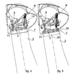
- a first yoke 1 is shown which is mountable on the inside of a windmill's blade 2 such as shown in Figs. 4-9 .
- FIG. 1 clearly shows the first yoke 1 comprises at both its ends 3, 4 pins 5 that in use point at the inside of the blade 2 so as to be able to mount the first yoke 1 to the blade 2.
- pins 5 are placed at a position so as to be able to cooperate with pinholes 6 (see Fig. 7 ) that are circumferentially provided at an end of the windmill's blade 2; see for instance Fig. 7 and Fig. 8 showing one such pinhole.
- pinholes 6 are normally used for connecting the blade 2 to the windmill's cone 7.
- Fig. 2 shows a second yoke 8 of the lift construction of the invention, which is mountable in the cone 7 of the windmill.
- This second yoke 8 is provided with hoisting means 9', 9" that are connectable to the first yoke 1 shown in Fig. 1 or a part thereof, in particular to a sheave block 10 or pad eye provided on the first yoke 1.
- the hoisting means 9', 9" preferably include manually adjustable hoisting means 9" as shown in Fig. 2 .
- the said sheave block 10 or pad eye of the first yoke 1 and the hoisting means in the form of winch 9" of the second yoke 8 are provided as Fig. 1 and Fig. 2 respectively show, at the ends of the yokes 1, 8, which - as Figs. 4-9 clearly show - in use are distant from the windmills standard (not shown).
- Fig. 1 and Fig. 2 respectively also show that the first yoke 1 and the second yoke 8 comprise positioning means 11, 12 that cooperate with each other and are placed near to the ends of the yokes 1,8, which in use are closest to the windmill standard (not shown). That means that these positioning or pushing means 11, 12 are furthest away from the front end of the windmill's cone 7 as clearly shown in Figs. 4-9 .
- these positioning means 11, 12 of the first yoke 1 and the second yoke 8 it is possible to maintain a predefined alignment and distance between these ends of the yokes 1, 8 and consequently maintain the blade 2 in a predefined inclination with respect to the windmill's cone 7, also when the bolts are disconnected that are used to secure the blade 2 to the cone 7 of the windmill.
- Fig. 1 clearly shows that the first yoke 1 may advantageously be provided with a receptacle 11 and Fig. 2 shows that the second yoke 8 may be provided with an actuator 12 - or vice versa - which actuator 12 has an end that accurately fits in the receptacle 11 of the yoke 1 such that upon activation of the actuator 12 a predefined pressure may be applied to the receptacle 11 so as to balance the blade 2 of the windmill in the desired predefined angle and position. In this predefined angle and position the blade 2 of the windmill occupies an alignment with respect to the cone 7 of the windmill that allows it to be easily mounted or dismounted therefrom.
- the lift construction of the invention also preferably comprises a guiding arm 13 as shown in Fig. 3 .
- a lifting cable 14 may be guided which is to be connected to the first yoke 1 or a part thereof, in particular to a sheave block 10 or pad eye provided on the first yoke 1. This is shown in Fig. 9 .
- the guiding arm 13 is supported, for instance by connecting chains 15 as is shown in Fig. 3 to connect the arm 13 to the windmill cone 7.
- Fig. 4 the first yoke 1 has been mounted to the inside of the blade 2. This can easily be done by taking the yoke 1 up by a service hoist of the nacelle or through the inside of the windmill through the (not shown) standard to the cone 7, which cone gives ample room for persons and the lift construction of the invention.
- the second yoke 8 is mounted to the windmill's cone 7 and in accordance with the invention the first yoke 1 and the second yoke 8 are provided with positioning means 11, 12 and hoisting means 10, 9'.
- the positioning means 11, 12 and hoisting means 10, 9' of the yokes 1, 8 carryout a concerted operation so as to move the windmill's blade 2 away from the cone 7 in a line that substantially coincides with the blade's orientation when in the mounted position as shown in Fig. 4 .
- This line of movement corresponds to the body axis indicated with centre-line 16.
- Fig. 7 it is shown that the distance between the blade 2 and the cone 7 of the windmill is further increased by substantially vertically lowering the blade 2 from the cone 7. This gives room for introducing a helpline 17 into the area of the cone 7 which serves to subsequently introduce a guiding arm 13 for a lifting cable 14 into the cone 7.
- Fig. 8 shows that this guiding arm 13 is connected to the second yoke 8 whereafter subsequently the lifting cable 14 is moved through and down to the hoisting means 10 or pad eye of the yoke 1 that connects to the blade 2.
- Fig. 9 it is clearly shown that indeed the lifting cable 14 connects to the hoisting means 10 of the first yoke 1. This allows that by simply operating from the ground the blade 2 may be further lowered so as to receive it eventually at the ground for further handling.
- the method for raising a blade 2 and mounting it to the cone 7 of a windmill operates vice versa and requires no further elucidation.
Landscapes
- Engineering & Computer Science (AREA)
- Mechanical Engineering (AREA)
- Civil Engineering (AREA)
- Structural Engineering (AREA)
- Life Sciences & Earth Sciences (AREA)
- Sustainable Development (AREA)
- Sustainable Energy (AREA)
- Chemical & Material Sciences (AREA)
- Combustion & Propulsion (AREA)
- General Engineering & Computer Science (AREA)
- Wind Motors (AREA)
Claims (15)
- Hubkonstruktion zum Heben und Senken eines Blattes (2) eines Windrades in die und aus seiner Befestigungsposition an einem drehbaren Konus (7) des Windrades, wobei ein Joch in dem Konus montierbar ist, dadurch gekennzeichnet, dass sie zwei Joche umfasst:- ein erstes Joch (1) der zwei Joche, das auf der Innenseite des Blattes (9) montierbar ist, und- ein zweites Joch (8) der zwei Joche, das im Konus (7) des Windrades montierbar ist,wobei das erste Joch (1) und das zweite Joch (8) zum Zusammenwirken angeordnet sind, wobei
das erste Joch (1) und das zweite Joch (8) zusammenwirkende Hubmittel (10, 9') haben, welche an den Enden der Joche vorgesehen sind, die im Einsatz entfernt von der Gebrauchslage des Windrades sind, und
dadurch, dass das erste Joch (1) und das zweite Joch (8) zusammenwirkende Positionierungsmittel (11, 12) in der Nähe der Enden der Joche (1, 8) haben, die im Einsatz der Gebrauchslage des Windrades am nächsten sind, um zumindest eine vorgegebene Ausrichtung und/oder Entfernung zwischen den Enden der Joche (1, 8) aufrechtzuhalten. - Hubkonstruktion nach Anspruch 1, dadurch gekennzeichnet, dass das erste Joch (1) einen Aufnahmebehälter (11) hat und das zweite Joch (8) einen Aktor (12) hat oder umgekehrt, wobei der Aktor (12) ein Ende hat, das in den Aufnahmebehälter (11) passt, so dass bei Betätigung des Aktors (12) ein vorgegebener Druck auf den Aufnahmebehälter (11) ausgeübt wird, um so das Blatt (2) des Windrades unter einem vorgegebenen. Winkel und/oder Position auszubalancieren.
- Hubkonstruktion nach Anspruch 2, dadurch gekennzeichnet, dass bei dem vorgegebenen Winkel und/oder der Position das Blatt (2) des Windrades eine Position relativ zum Konus (7) des Windrades einnimmt, die es ermöglicht, dass es am Konus (7) montiert oder von demselben abgenommen werden kann.
- Hubkonstruktion nach einem der Ansprüche 1 bis 3, dadurch gekennzeichnet, dass das erste Joch (1) an seinen beiden Enden (3, 4) Stifte (5) hat, die beim Einsatz zur Innenseite des Blatts zum Montieren des ersten Jochs (1) am Blatt (2) weisen.
- Hubkonstruktion nach Anspruch 4, dadurch gekennzeichnet, dass die Stifte (5) an einer Position angeordnet sind, wo sie mit Stiftlöchern (6) im Blatt (2) zusammenwirken können, die zum Verbinden des Blatts (2) mit dem Konus (7) des Windrades bestimmt sind.
- Hubkonstruktion nach einem der vorherigen Ansprüche, dadurch gekennzeichnet, dass das zweite Joch (8) mit Hubmitteln (9', 9") versehen ist, die mit dem ersten Joch (1) oder einem Teil desselben verbunden werden können, insbesondere mit Hubmitteln (10) oder einem Deckauge des ersten Jochs (1).
- Hubkonstruktion nach Anspruch 6, dadurch gekennzeichnet, dass das Hubmittel (9") des zweiten Jochs (8) einstellbar ist.
- Hubkonstruktion nach einem der vorherigen Ansprüche, dadurch gekennzeichnet, dass sie Folgendes umfasst:- einen Führungsarm (13) für ein Hubseil (14), wobei der Arm mit dem zweiten Joch (8) verbunden werden kann.
- Hubkonstruktion nach Anspruch 8, dadurch gekennzeichnet, dass das Hubseil (14) mit dem ersten Joch (1) oder einem Teil desselben verbunden werden kann, insbesondere mit dem Hubmittel (10) oder einem Deckauge, das auf dem ersten Joch (1) vorgesehen ist.
- Hubkonstruktion nach Anspruch 8 oder 9, dadurch gekennzeichnet, dass der Führungsarm (13) gestützt wird, vorzugsweise von Verbindungsketten (15), die den Arm (13) mit dem Konus (7) des Windrades oder einem Teil desselben verbinden.
- Joch (1), das sich zum Montieren an der Innenseite eines Windradblattes (2) eignet, welches entgegengesetzte Enden (3, 4) hat, die beim Einsatz der Innenseite des Blattes (2) zugewandt sind, wobei die Enden (3, 4) zueinander und voneinander bewegt werden können, dadurch gekennzeichnet, dass es mindestens ein Hubmittel (10) oder Deckauge nahe einem Ende (4) hat, welches einer Innenseite eines Windradblattes (2) zugewandt ist.
- Joch (1) nach Anspruch 11, dadurch gekennzeichnet, dass an einem Ende (3) gegenüber dem Ende (4), wo sich ein Hubmittel (10) oder Deckauge befindet, Mittel (11) vorgesehen ist, das zum Zusammenwirken mit einem weiteren Mittel (12) eines anderen Jochs (8) angeordnet ist, um so beide Joche (1, 8) auseinanderzudrücken.
- Joch (1) nach einem der Ansprüche 11 bis 12, dadurch gekennzeichnet, dass es an seinen beiden Enden (3, 4) Stifte (5) umfasst, die beim Einsatz zum Befestigen an einem Blatt (2) eines Windrades dienen.
- Joch (1) nach Anspruch 13, dadurch gekennzeichnet, dass die Stifte (5) an einer Position angeordnet sind, wo sie mit Stiftlöchern (6) im Blatt (2) zusammenwirken können, die zum Verbinden des Blatts (2) mit dem Konus (7) des Windrades bestimmt sind.
- Verfahren zum Befestigen eines Windradblattes (2) an einem Konus (7) eines Windrades oder zum Abnehmen von demselben, wobei ein Joch im Konus (7) montiert ist, dadurch gekennzeichnet, dass zwei Joche (1, 8) eingesetzt werden, wobei:- ein erstes Joch (1) an der Blattinnenseite montiert ist, und- ein zweites Joch (8) im Konus (7) des Windrades montiert ist, und
wobei das erste Joch (1) und das zweite Joch (8) mit Positionierungsmitteln (11, 12) und Hubmitteln (10, 9') versehen sind, und das Verfahren so ausgeführt wird, dass- wenn das Blatt (2) sich in der Nähe des Konus (7) des Windrades befindet, die Positionierungsmittel (11, 12) und die Hubmittel (10, 9') der Joche (1, 8) eine konzertierte Operation ausführen, um so das Windradblatt (2) zum Konus (7) hin oder von demselben weg in einer Linie zu bewegen, die im Wesentlichen mit der Ausrichtung des Blatts in der montierten Position zusammenfällt, und dass- wenn das Blatt (2) sich jenseits einer vorgegebenen Distanz gegenüber dem Konus (7) des Windrades befindet, das Blatt (2) im Wesentlichen vertikal angehoben oder abgesenkt wird.
Applications Claiming Priority (2)
| Application Number | Priority Date | Filing Date | Title |
|---|---|---|---|
| NL1035301A NL1035301C1 (nl) | 2008-04-16 | 2008-04-16 | Lift- en daalmethode middels een demontabele hijsinrichting. |
| PCT/NL2009/050135 WO2009128708A2 (en) | 2008-04-16 | 2009-03-23 | Method and lift construction for lifting and lowering a blade of a windmill |
Publications (2)
| Publication Number | Publication Date |
|---|---|
| EP2279345A2 EP2279345A2 (de) | 2011-02-02 |
| EP2279345B1 true EP2279345B1 (de) | 2013-12-11 |
Family
ID=40210356
Family Applications (1)
| Application Number | Title | Priority Date | Filing Date |
|---|---|---|---|
| EP09732534.4A Not-in-force EP2279345B1 (de) | 2008-04-16 | 2009-03-23 | Verfahren und hubkonstruktion zum anheben und absenken eines flügels einer windmühle |
Country Status (8)
| Country | Link |
|---|---|
| US (1) | US8651462B2 (de) |
| EP (1) | EP2279345B1 (de) |
| AU (1) | AU2009236783B2 (de) |
| CA (1) | CA2721676C (de) |
| DK (1) | DK2279345T5 (de) |
| ES (1) | ES2451342T3 (de) |
| NL (1) | NL1035301C1 (de) |
| WO (1) | WO2009128708A2 (de) |
Families Citing this family (37)
| Publication number | Priority date | Publication date | Assignee | Title |
|---|---|---|---|---|
| NL1037075C2 (nl) * | 2009-06-25 | 2010-06-09 | Dutch Heavy Lift Concepts B V | Demontabele lierinrichting. |
| CA2784625A1 (en) * | 2009-11-30 | 2011-06-03 | Clipper Windpower, Inc. | Wind turbine blade lowering apparatus |
| CN102713279B (zh) * | 2010-01-14 | 2015-02-18 | 歌美飒创新技术公司 | 叶片提升元件及其相关方法 |
| WO2011095167A2 (en) | 2010-02-08 | 2011-08-11 | Okutan Ufuk | A method for lifting and lowering of a wind turbine blade |
| DK2441950T3 (da) * | 2010-10-15 | 2014-06-10 | Alstom Renovables Espana Sl | Vinge til en vindmølle |
| ES2564260T3 (es) * | 2010-11-18 | 2016-03-21 | Vestas Wind Systems A/S | Método para manipular sin grúa una pala de turbina eólica por medio de un buje de turbina |
| GB2487083A (en) * | 2011-01-07 | 2012-07-11 | Vestas Wind Sys As | Wind turbine blade bearing removal apparatus and method |
| AU2011310939A1 (en) | 2011-04-05 | 2012-10-18 | Mitsubishi Heavy Industries, Ltd. | Power generating apparatus of renewable energy type |
| EP2570660B1 (de) | 2011-08-10 | 2014-01-08 | Mitsubishi Heavy Industries, Ltd. | Vorrichtung zur stromerzeugung aus erneuerbarer energie |
| GB2496129B (en) * | 2011-10-31 | 2013-09-25 | Technip France | Cable installation apparatus for mounting on a flanged structure |
| US9745953B2 (en) * | 2012-10-23 | 2017-08-29 | General Electric Company | Method and system for replacing a single wind turbine blade |
| ITMI20130288A1 (it) * | 2013-02-27 | 2014-08-28 | Wilic Sarl | Metodo e sistema di montaggio e/o smontaggio di una macchina elettrica rotante di un aerogeneratore |
| US9394886B2 (en) * | 2013-03-07 | 2016-07-19 | General Electric Company | System and method for re-indexing a pitch bearing of a wind turbine |
| US9429138B2 (en) * | 2013-08-09 | 2016-08-30 | Gamesa Innovation & Technology, S.L. | Apparatus, system and method for wind turbine component replacement |
| US10113530B2 (en) | 2014-02-20 | 2018-10-30 | General Electric Company | Methods and systems for removing and/or installing wind turbine rotor blades |
| US9638163B2 (en) | 2014-02-20 | 2017-05-02 | General Electric Company | Methods and systems for removing and/or installing wind turbine rotor blades |
| US9964095B2 (en) * | 2014-04-21 | 2018-05-08 | General Electric Company | Method and system for servicing wind turbine rotor |
| JP2017515048A (ja) * | 2014-04-30 | 2017-06-08 | ウィンドケア インディア プライベート リミテッドWindcare India Pvt Ltd | 風力タービンブレードの解体および再取り付け方法およびシステム |
| ES2556997B1 (es) | 2014-07-07 | 2016-12-12 | Gamesa Innovation & Technology, S.L. | Método y dispositivo de sustitución de pala en aerogeneradores |
| US9651021B2 (en) | 2014-09-09 | 2017-05-16 | General Electric Company | System and method for removing and/or installing a rotor blade of a wind turbine |
| CN104625562B (zh) * | 2014-12-23 | 2017-08-11 | 新疆金风科技股份有限公司 | 风力发电机组的叶片的错位纠正方法 |
| CA2927197C (en) * | 2015-04-27 | 2019-04-09 | General Electric Company | Method and system for replacing a single wind turbine blade |
| US9821417B2 (en) | 2015-05-07 | 2017-11-21 | General Electric Company | System and method for replacing a pitch bearing |
| US9890022B2 (en) * | 2015-05-07 | 2018-02-13 | General Electric Company | Method for suspending a rotor blade from a hub of a wind turbine |
| MX2018002835A (es) * | 2015-09-04 | 2019-01-14 | Barnhart Crane And Rigging Co | Sistema y método de retirada e instalación de pala de aerogenerador. |
| US10066601B2 (en) | 2015-10-22 | 2018-09-04 | General Electric Company | System and method for manufacturing wind turbine rotor blades for simplified installation and removal |
| DE102016111514A1 (de) * | 2016-06-23 | 2017-12-28 | Wobben Properties Gmbh | Verfahren zum Errichten einer Windenergieanlage und Hebetraverse zur Montage eines Rotorblatts einer Windenergieanlage |
| CN110637156B (zh) * | 2017-03-07 | 2022-05-27 | 西门子歌美飒可再生能源公司 | 用于组装风力涡轮机的组装系统及方法 |
| US10508645B2 (en) | 2017-07-17 | 2019-12-17 | General Electric Company | System and method for suspending a rotor blade of a wind turbine uptower |
| US10598158B2 (en) * | 2017-07-20 | 2020-03-24 | General Electric Company | System and method for removing or installing rotor blade hardware of a wind turbine |
| CA3071958C (en) * | 2017-08-03 | 2023-10-03 | Barnhart Crane and Rigging Co. | Wind tubine bearing removal and installation device and method |
| CN108087204B (zh) * | 2017-12-08 | 2020-05-12 | 北京金风科创风电设备有限公司 | 风力发电机组的吊装对正系统及方法 |
| DK3502465T3 (da) * | 2017-12-22 | 2021-03-01 | Gen Electric | Hejsningstilbehør til vindmøller, kits og fremgangsmåder |
| DK180872B1 (en) | 2019-05-02 | 2022-06-08 | Liftra Ip Aps | Self-hoisting crane system and method for hoisting a self-hoisting crane |
| EP4048887A1 (de) * | 2019-10-22 | 2022-08-31 | LiftWerx Holdings Inc. | Hubsystem für ein rotorblatt einer windenergieanlage |
| EP3901451B1 (de) * | 2020-04-21 | 2023-06-07 | Vestas Wind Systems A/S | Windturbinenschaufelinstallation |
| WO2025214581A1 (en) * | 2024-04-09 | 2025-10-16 | General Electric Renovables España S.L. | Systems for aligning wind turbine blades and hubs and methods for mounting wind turbine blades |
Family Cites Families (19)
| Publication number | Priority date | Publication date | Assignee | Title |
|---|---|---|---|---|
| FR2649087B1 (fr) * | 1989-06-28 | 1991-10-11 | Aerospatiale | Dispositif pour la prehension d'une charge en bout en vue de sa manutention et installation de manutention pourvue d'un tel dispositif de prehension |
| JPH0351182A (ja) * | 1989-07-19 | 1991-03-05 | Matsushita Electric Ind Co Ltd | 光記録媒体 |
| JPH0351182U (de) * | 1989-09-22 | 1991-05-17 | ||
| AT401674B (de) * | 1994-09-26 | 1996-11-25 | Hehenberger Gerald Dipl Ing | Windkraftanlage |
| DE10224439C5 (de) * | 2002-06-01 | 2009-12-31 | Aloys Wobben | Verfahren zur Montage/Demontage von Komponenten einer Windenergieanlage |
| DE10303555B4 (de) * | 2003-01-29 | 2007-01-25 | Aloys Wobben | Verfahren zur kranlosen Montage eines Rotorblattes einer Windenergieanlage |
| JP4210540B2 (ja) * | 2003-03-27 | 2009-01-21 | 株式会社荏原製作所 | ブレードのメンテナンスが容易な風車及び風力発電装置 |
| DE202004016460U1 (de) * | 2004-10-25 | 2004-12-23 | Geo. Gleistein & Sohn Gmbh | Vorrichtung zum Austauschen eines Rotorblatts einer Windkraftanlage |
| DE102004056340B4 (de) * | 2004-11-22 | 2010-11-18 | Repower Systems Ag | Vorrichtung und Verfahren zur Montage und/oder Demontage eines Bauteils einer Windkraftanlage |
| JP2006152862A (ja) * | 2004-11-26 | 2006-06-15 | Ishikawajima Harima Heavy Ind Co Ltd | 風力発電装置におけるブレードの取り付け方法及び取り外し方法 |
| AU2007264206B2 (en) * | 2006-06-30 | 2011-06-16 | Vestas Wind Systems A/S | Lifting equipment for handling a wind turbine component and a method for handling a wind turbine component |
| ES2322000B1 (es) * | 2006-12-14 | 2010-03-11 | GAMESA INNOVATION & TECHNOLOGY, S.L. | Un metodo para montar el rotor de un aerogenerador. |
| JP4885073B2 (ja) * | 2007-06-20 | 2012-02-29 | 三菱重工業株式会社 | 風車回転翼の吊下げ装置、風車回転翼の取付け方法、および風力発電装置の建設方法 |
| DK2226502T3 (da) * | 2009-03-03 | 2013-03-25 | Siemens Ag | Fremgangsmåde og indretning til installering af en vindmølle |
| US20100254813A1 (en) * | 2009-04-02 | 2010-10-07 | Frontier Pro Services | Winch servicing of wind turbines |
| DE102009056245B4 (de) * | 2009-12-01 | 2014-02-20 | Aerodyn Engineering Gmbh | Windenergieanlage mit Hebevorrichtung |
| DK2369174T3 (da) * | 2010-03-09 | 2013-03-11 | Lm Glasfiber As | En fremgangsmåde til kranfri montering eller afmontering af en vindmøllevinge på et vindenergianlæg |
| GB2483677B (en) * | 2010-09-15 | 2014-04-16 | Vestas Wind Sys As | An apparatus for and method of mounting wind turbine blades on a wind turbine tower |
| JP5663249B2 (ja) * | 2010-09-17 | 2015-02-04 | 株式会社日立製作所 | 風力発電装置のブレード吊上方法及びブレード吊上治具 |
-
2008
- 2008-04-16 NL NL1035301A patent/NL1035301C1/nl not_active IP Right Cessation
-
2009
- 2009-03-23 CA CA2721676A patent/CA2721676C/en active Active
- 2009-03-23 WO PCT/NL2009/050135 patent/WO2009128708A2/en not_active Ceased
- 2009-03-23 EP EP09732534.4A patent/EP2279345B1/de not_active Not-in-force
- 2009-03-23 DK DK09732534.4T patent/DK2279345T5/da active
- 2009-03-23 ES ES09732534.4T patent/ES2451342T3/es active Active
- 2009-03-23 US US12/988,272 patent/US8651462B2/en not_active Expired - Fee Related
- 2009-03-23 AU AU2009236783A patent/AU2009236783B2/en not_active Ceased
Also Published As
| Publication number | Publication date |
|---|---|
| AU2009236783B2 (en) | 2013-04-04 |
| CA2721676C (en) | 2014-07-29 |
| WO2009128708A3 (en) | 2010-05-14 |
| NL1035301C1 (nl) | 2008-06-04 |
| DK2279345T3 (en) | 2014-03-17 |
| US20110042632A1 (en) | 2011-02-24 |
| US8651462B2 (en) | 2014-02-18 |
| ES2451342T3 (es) | 2014-03-26 |
| WO2009128708A2 (en) | 2009-10-22 |
| CA2721676A1 (en) | 2009-10-22 |
| DK2279345T5 (da) | 2014-03-31 |
| AU2009236783A1 (en) | 2009-10-22 |
| EP2279345A2 (de) | 2011-02-02 |
Similar Documents
| Publication | Publication Date | Title |
|---|---|---|
| EP2279345B1 (de) | Verfahren und hubkonstruktion zum anheben und absenken eines flügels einer windmühle | |
| US10988351B2 (en) | Nacelle-mounted lift system for wind turbine | |
| EP2118483B2 (de) | Verfahren zum bewegen eines windturbinenbauteils, wie zum beispiel einer windturbinennabe, aus einer transportposition in eine windturbinenmontageposition in oder an der gondel, hauptwelle oder nabe, handhabungseinheit, windturbinennabe und verwendung davon | |
| EP1668244B1 (de) | Ausrüstung zur anbringung an der nabe einer windturbine und verfahren zur durchführung von wartungsarbeiten an einer windturbine unter verwendung von solcher ausrüstung | |
| EP2604850B1 (de) | Hebearm | |
| CA2928179C (en) | System and method for replacing a pitch bearing | |
| CN103443450B (zh) | 风轮机叶片轴承拆除装置和方法 | |
| EP2982862A1 (de) | Verfahren und vorrichtung zum austauschen von schaufeln bei windturbinen | |
| CN109952263B (zh) | 提升组件 | |
| CN1989341A (zh) | 用于临时使用以移动或更换部件和安装风力涡轮发电机的可移动的独立起重系统 | |
| CA2848822A1 (en) | Method and device for mounting a rotor of a wind energy plant | |
| CN211226089U (zh) | 一种塔式起重机连续顶升加节的作业机构 | |
| US20210163268A1 (en) | A method of handling a wind turbine component and a wind turbine with a crane | |
| JP2019520509A (ja) | 風力タービンを建設する方法および風力タービンのローターブレードを取り付けるための吊りビーム | |
| CN107827003B (zh) | 用于稳定起重机的设备 | |
| CN114074899A (zh) | 用于伸缩吊臂的快速装配头及其装配方法 | |
| EP3020622B1 (de) | System und Hebeeinheit zum Heben von Lasten unterschiedlichen Gewichts | |
| CN121100103A (zh) | 用于起重机系统的方法及辅助臂 | |
| CN114955902A (zh) | 一种起重机变幅装置、变幅装置运输车及桁架臂起重机 | |
| CN116969306A (zh) | 吊运装置及其吊运方法 | |
| CN120756989A (zh) | 一种闸门起吊设备及起吊方法 |
Legal Events
| Date | Code | Title | Description |
|---|---|---|---|
| PUAI | Public reference made under article 153(3) epc to a published international application that has entered the european phase |
Free format text: ORIGINAL CODE: 0009012 |
|
| 17P | Request for examination filed |
Effective date: 20101116 |
|
| AK | Designated contracting states |
Kind code of ref document: A2 Designated state(s): AT BE BG CH CY CZ DE DK EE ES FI FR GB GR HR HU IE IS IT LI LT LU LV MC MK MT NL NO PL PT RO SE SI SK TR |
|
| AX | Request for extension of the european patent |
Extension state: AL BA RS |
|
| DAX | Request for extension of the european patent (deleted) | ||
| REG | Reference to a national code |
Ref country code: DE Ref legal event code: R079 Ref document number: 602009020671 Country of ref document: DE Free format text: PREVIOUS MAIN CLASS: F03D0001000000 Ipc: B66C0023180000 |
|
| RIC1 | Information provided on ipc code assigned before grant |
Ipc: F03D 1/00 20060101ALI20130528BHEP Ipc: B66C 23/18 20060101AFI20130528BHEP |
|
| GRAP | Despatch of communication of intention to grant a patent |
Free format text: ORIGINAL CODE: EPIDOSNIGR1 |
|
| INTG | Intention to grant announced |
Effective date: 20130730 |
|
| GRAS | Grant fee paid |
Free format text: ORIGINAL CODE: EPIDOSNIGR3 |
|
| GRAA | (expected) grant |
Free format text: ORIGINAL CODE: 0009210 |
|
| AK | Designated contracting states |
Kind code of ref document: B1 Designated state(s): AT BE BG CH CY CZ DE DK EE ES FI FR GB GR HR HU IE IS IT LI LT LU LV MC MK MT NL NO PL PT RO SE SI SK TR |
|
| REG | Reference to a national code |
Ref country code: GB Ref legal event code: FG4D |
|
| REG | Reference to a national code |
Ref country code: CH Ref legal event code: EP |
|
| REG | Reference to a national code |
Ref country code: AT Ref legal event code: REF Ref document number: 644466 Country of ref document: AT Kind code of ref document: T Effective date: 20140115 |
|
| REG | Reference to a national code |
Ref country code: IE Ref legal event code: FG4D |
|
| REG | Reference to a national code |
Ref country code: DE Ref legal event code: R096 Ref document number: 602009020671 Country of ref document: DE Effective date: 20140130 |
|
| REG | Reference to a national code |
Ref country code: NL Ref legal event code: T3 |
|
| REG | Reference to a national code |
Ref country code: DK Ref legal event code: T3 Effective date: 20140311 |
|
| REG | Reference to a national code |
Ref country code: ES Ref legal event code: FG2A Ref document number: 2451342 Country of ref document: ES Kind code of ref document: T3 Effective date: 20140326 |
|
| REG | Reference to a national code |
Ref country code: DK Ref legal event code: T5 Effective date: 20140324 |
|
| REG | Reference to a national code |
Ref country code: AT Ref legal event code: MK05 Ref document number: 644466 Country of ref document: AT Kind code of ref document: T Effective date: 20131211 |
|
| PG25 | Lapsed in a contracting state [announced via postgrant information from national office to epo] |
Ref country code: HR Free format text: LAPSE BECAUSE OF FAILURE TO SUBMIT A TRANSLATION OF THE DESCRIPTION OR TO PAY THE FEE WITHIN THE PRESCRIBED TIME-LIMIT Effective date: 20131211 Ref country code: SE Free format text: LAPSE BECAUSE OF FAILURE TO SUBMIT A TRANSLATION OF THE DESCRIPTION OR TO PAY THE FEE WITHIN THE PRESCRIBED TIME-LIMIT Effective date: 20131211 Ref country code: LT Free format text: LAPSE BECAUSE OF FAILURE TO SUBMIT A TRANSLATION OF THE DESCRIPTION OR TO PAY THE FEE WITHIN THE PRESCRIBED TIME-LIMIT Effective date: 20131211 Ref country code: FI Free format text: LAPSE BECAUSE OF FAILURE TO SUBMIT A TRANSLATION OF THE DESCRIPTION OR TO PAY THE FEE WITHIN THE PRESCRIBED TIME-LIMIT Effective date: 20131211 Ref country code: NO Free format text: LAPSE BECAUSE OF FAILURE TO SUBMIT A TRANSLATION OF THE DESCRIPTION OR TO PAY THE FEE WITHIN THE PRESCRIBED TIME-LIMIT Effective date: 20140311 |
|
| REG | Reference to a national code |
Ref country code: LT Ref legal event code: MG4D |
|
| PG25 | Lapsed in a contracting state [announced via postgrant information from national office to epo] |
Ref country code: CY Free format text: LAPSE BECAUSE OF FAILURE TO SUBMIT A TRANSLATION OF THE DESCRIPTION OR TO PAY THE FEE WITHIN THE PRESCRIBED TIME-LIMIT Effective date: 20131211 Ref country code: LV Free format text: LAPSE BECAUSE OF FAILURE TO SUBMIT A TRANSLATION OF THE DESCRIPTION OR TO PAY THE FEE WITHIN THE PRESCRIBED TIME-LIMIT Effective date: 20131211 Ref country code: AT Free format text: LAPSE BECAUSE OF FAILURE TO SUBMIT A TRANSLATION OF THE DESCRIPTION OR TO PAY THE FEE WITHIN THE PRESCRIBED TIME-LIMIT Effective date: 20131211 |
|
| PG25 | Lapsed in a contracting state [announced via postgrant information from national office to epo] |
Ref country code: IS Free format text: LAPSE BECAUSE OF FAILURE TO SUBMIT A TRANSLATION OF THE DESCRIPTION OR TO PAY THE FEE WITHIN THE PRESCRIBED TIME-LIMIT Effective date: 20140411 Ref country code: EE Free format text: LAPSE BECAUSE OF FAILURE TO SUBMIT A TRANSLATION OF THE DESCRIPTION OR TO PAY THE FEE WITHIN THE PRESCRIBED TIME-LIMIT Effective date: 20131211 |
|
| PG25 | Lapsed in a contracting state [announced via postgrant information from national office to epo] |
Ref country code: CZ Free format text: LAPSE BECAUSE OF FAILURE TO SUBMIT A TRANSLATION OF THE DESCRIPTION OR TO PAY THE FEE WITHIN THE PRESCRIBED TIME-LIMIT Effective date: 20131211 Ref country code: PT Free format text: LAPSE BECAUSE OF FAILURE TO SUBMIT A TRANSLATION OF THE DESCRIPTION OR TO PAY THE FEE WITHIN THE PRESCRIBED TIME-LIMIT Effective date: 20140411 Ref country code: SK Free format text: LAPSE BECAUSE OF FAILURE TO SUBMIT A TRANSLATION OF THE DESCRIPTION OR TO PAY THE FEE WITHIN THE PRESCRIBED TIME-LIMIT Effective date: 20131211 Ref country code: RO Free format text: LAPSE BECAUSE OF FAILURE TO SUBMIT A TRANSLATION OF THE DESCRIPTION OR TO PAY THE FEE WITHIN THE PRESCRIBED TIME-LIMIT Effective date: 20131211 Ref country code: PL Free format text: LAPSE BECAUSE OF FAILURE TO SUBMIT A TRANSLATION OF THE DESCRIPTION OR TO PAY THE FEE WITHIN THE PRESCRIBED TIME-LIMIT Effective date: 20131211 |
|
| REG | Reference to a national code |
Ref country code: DE Ref legal event code: R097 Ref document number: 602009020671 Country of ref document: DE |
|
| PLBE | No opposition filed within time limit |
Free format text: ORIGINAL CODE: 0009261 |
|
| STAA | Information on the status of an ep patent application or granted ep patent |
Free format text: STATUS: NO OPPOSITION FILED WITHIN TIME LIMIT |
|
| PG25 | Lapsed in a contracting state [announced via postgrant information from national office to epo] |
Ref country code: LU Free format text: LAPSE BECAUSE OF FAILURE TO SUBMIT A TRANSLATION OF THE DESCRIPTION OR TO PAY THE FEE WITHIN THE PRESCRIBED TIME-LIMIT Effective date: 20140323 |
|
| REG | Reference to a national code |
Ref country code: CH Ref legal event code: PL |
|
| 26N | No opposition filed |
Effective date: 20140912 |
|
| REG | Reference to a national code |
Ref country code: DE Ref legal event code: R097 Ref document number: 602009020671 Country of ref document: DE Effective date: 20140912 |
|
| REG | Reference to a national code |
Ref country code: IE Ref legal event code: MM4A |
|
| PG25 | Lapsed in a contracting state [announced via postgrant information from national office to epo] |
Ref country code: LI Free format text: LAPSE BECAUSE OF NON-PAYMENT OF DUE FEES Effective date: 20140331 Ref country code: IE Free format text: LAPSE BECAUSE OF NON-PAYMENT OF DUE FEES Effective date: 20140323 Ref country code: CH Free format text: LAPSE BECAUSE OF NON-PAYMENT OF DUE FEES Effective date: 20140331 |
|
| PG25 | Lapsed in a contracting state [announced via postgrant information from national office to epo] |
Ref country code: SI Free format text: LAPSE BECAUSE OF FAILURE TO SUBMIT A TRANSLATION OF THE DESCRIPTION OR TO PAY THE FEE WITHIN THE PRESCRIBED TIME-LIMIT Effective date: 20131211 |
|
| PG25 | Lapsed in a contracting state [announced via postgrant information from national office to epo] |
Ref country code: MT Free format text: LAPSE BECAUSE OF FAILURE TO SUBMIT A TRANSLATION OF THE DESCRIPTION OR TO PAY THE FEE WITHIN THE PRESCRIBED TIME-LIMIT Effective date: 20131211 |
|
| REG | Reference to a national code |
Ref country code: FR Ref legal event code: PLFP Year of fee payment: 8 |
|
| PG25 | Lapsed in a contracting state [announced via postgrant information from national office to epo] |
Ref country code: MC Free format text: LAPSE BECAUSE OF FAILURE TO SUBMIT A TRANSLATION OF THE DESCRIPTION OR TO PAY THE FEE WITHIN THE PRESCRIBED TIME-LIMIT Effective date: 20131211 |
|
| PG25 | Lapsed in a contracting state [announced via postgrant information from national office to epo] |
Ref country code: IT Free format text: LAPSE BECAUSE OF FAILURE TO SUBMIT A TRANSLATION OF THE DESCRIPTION OR TO PAY THE FEE WITHIN THE PRESCRIBED TIME-LIMIT Effective date: 20131211 Ref country code: GR Free format text: LAPSE BECAUSE OF FAILURE TO SUBMIT A TRANSLATION OF THE DESCRIPTION OR TO PAY THE FEE WITHIN THE PRESCRIBED TIME-LIMIT Effective date: 20140312 Ref country code: BG Free format text: LAPSE BECAUSE OF FAILURE TO SUBMIT A TRANSLATION OF THE DESCRIPTION OR TO PAY THE FEE WITHIN THE PRESCRIBED TIME-LIMIT Effective date: 20131211 |
|
| PG25 | Lapsed in a contracting state [announced via postgrant information from national office to epo] |
Ref country code: TR Free format text: LAPSE BECAUSE OF FAILURE TO SUBMIT A TRANSLATION OF THE DESCRIPTION OR TO PAY THE FEE WITHIN THE PRESCRIBED TIME-LIMIT Effective date: 20131211 Ref country code: HU Free format text: LAPSE BECAUSE OF FAILURE TO SUBMIT A TRANSLATION OF THE DESCRIPTION OR TO PAY THE FEE WITHIN THE PRESCRIBED TIME-LIMIT; INVALID AB INITIO Effective date: 20090323 |
|
| REG | Reference to a national code |
Ref country code: FR Ref legal event code: PLFP Year of fee payment: 9 |
|
| REG | Reference to a national code |
Ref country code: FR Ref legal event code: PLFP Year of fee payment: 10 |
|
| PG25 | Lapsed in a contracting state [announced via postgrant information from national office to epo] |
Ref country code: MK Free format text: LAPSE BECAUSE OF FAILURE TO SUBMIT A TRANSLATION OF THE DESCRIPTION OR TO PAY THE FEE WITHIN THE PRESCRIBED TIME-LIMIT Effective date: 20131211 |
|
| PGFP | Annual fee paid to national office [announced via postgrant information from national office to epo] |
Ref country code: FR Payment date: 20230327 Year of fee payment: 15 Ref country code: DK Payment date: 20230329 Year of fee payment: 15 |
|
| PGFP | Annual fee paid to national office [announced via postgrant information from national office to epo] |
Ref country code: GB Payment date: 20230327 Year of fee payment: 15 Ref country code: DE Payment date: 20230329 Year of fee payment: 15 Ref country code: BE Payment date: 20230327 Year of fee payment: 15 |
|
| PGFP | Annual fee paid to national office [announced via postgrant information from national office to epo] |
Ref country code: NL Payment date: 20230326 Year of fee payment: 15 |
|
| PGFP | Annual fee paid to national office [announced via postgrant information from national office to epo] |
Ref country code: ES Payment date: 20230403 Year of fee payment: 15 |
|
| REG | Reference to a national code |
Ref country code: DE Ref legal event code: R119 Ref document number: 602009020671 Country of ref document: DE |
|
| REG | Reference to a national code |
Ref country code: DK Ref legal event code: EBP Effective date: 20240331 |
|
| REG | Reference to a national code |
Ref country code: NL Ref legal event code: MM Effective date: 20240401 |
|
| GBPC | Gb: european patent ceased through non-payment of renewal fee |
Effective date: 20240323 |
|
| PG25 | Lapsed in a contracting state [announced via postgrant information from national office to epo] |
Ref country code: NL Free format text: LAPSE BECAUSE OF NON-PAYMENT OF DUE FEES Effective date: 20240401 |
|
| REG | Reference to a national code |
Ref country code: BE Ref legal event code: MM Effective date: 20240331 |
|
| PG25 | Lapsed in a contracting state [announced via postgrant information from national office to epo] |
Ref country code: NL Free format text: LAPSE BECAUSE OF NON-PAYMENT OF DUE FEES Effective date: 20240401 |
|
| PG25 | Lapsed in a contracting state [announced via postgrant information from national office to epo] |
Ref country code: DE Free format text: LAPSE BECAUSE OF NON-PAYMENT OF DUE FEES Effective date: 20241001 |
|
| PG25 | Lapsed in a contracting state [announced via postgrant information from national office to epo] |
Ref country code: BE Free format text: LAPSE BECAUSE OF NON-PAYMENT OF DUE FEES Effective date: 20240331 |
|
| PG25 | Lapsed in a contracting state [announced via postgrant information from national office to epo] |
Ref country code: GB Free format text: LAPSE BECAUSE OF NON-PAYMENT OF DUE FEES Effective date: 20240323 |
|
| PG25 | Lapsed in a contracting state [announced via postgrant information from national office to epo] |
Ref country code: FR Free format text: LAPSE BECAUSE OF NON-PAYMENT OF DUE FEES Effective date: 20240331 |
|
| PG25 | Lapsed in a contracting state [announced via postgrant information from national office to epo] |
Ref country code: GB Free format text: LAPSE BECAUSE OF NON-PAYMENT OF DUE FEES Effective date: 20240323 Ref country code: FR Free format text: LAPSE BECAUSE OF NON-PAYMENT OF DUE FEES Effective date: 20240331 Ref country code: DE Free format text: LAPSE BECAUSE OF NON-PAYMENT OF DUE FEES Effective date: 20241001 Ref country code: BE Free format text: LAPSE BECAUSE OF NON-PAYMENT OF DUE FEES Effective date: 20240331 |
|
| PG25 | Lapsed in a contracting state [announced via postgrant information from national office to epo] |
Ref country code: DK Free format text: LAPSE BECAUSE OF NON-PAYMENT OF DUE FEES Effective date: 20240331 |
|
| PG25 | Lapsed in a contracting state [announced via postgrant information from national office to epo] |
Ref country code: ES Free format text: LAPSE BECAUSE OF NON-PAYMENT OF DUE FEES Effective date: 20240324 |