EP2278040A2 - Système de revêtement contenant un phase pyrochlor mixte de gadolinium - Google Patents
Système de revêtement contenant un phase pyrochlor mixte de gadolinium Download PDFInfo
- Publication number
- EP2278040A2 EP2278040A2 EP20100014408 EP10014408A EP2278040A2 EP 2278040 A2 EP2278040 A2 EP 2278040A2 EP 20100014408 EP20100014408 EP 20100014408 EP 10014408 A EP10014408 A EP 10014408A EP 2278040 A2 EP2278040 A2 EP 2278040A2
- Authority
- EP
- European Patent Office
- Prior art keywords
- layer
- ceramic layer
- yttrium
- aluminum
- chromium
- Prior art date
- Legal status (The legal status is an assumption and is not a legal conclusion. Google has not performed a legal analysis and makes no representation as to the accuracy of the status listed.)
- Withdrawn
Links
- 238000000576 coating method Methods 0.000 title description 12
- 229910052688 Gadolinium Inorganic materials 0.000 title description 5
- UIWYJDYFSGRHKR-UHFFFAOYSA-N gadolinium atom Chemical compound [Gd] UIWYJDYFSGRHKR-UHFFFAOYSA-N 0.000 title description 5
- 239000011248 coating agent Substances 0.000 title description 3
- 239000000919 ceramic Substances 0.000 claims abstract description 34
- 239000000758 substrate Substances 0.000 claims abstract description 14
- PXHVJJICTQNCMI-UHFFFAOYSA-N Nickel Chemical compound [Ni] PXHVJJICTQNCMI-UHFFFAOYSA-N 0.000 claims description 32
- 229910052727 yttrium Inorganic materials 0.000 claims description 20
- VWQVUPCCIRVNHF-UHFFFAOYSA-N yttrium atom Chemical compound [Y] VWQVUPCCIRVNHF-UHFFFAOYSA-N 0.000 claims description 20
- 229910017052 cobalt Inorganic materials 0.000 claims description 17
- 239000010941 cobalt Substances 0.000 claims description 17
- GUTLYIVDDKVIGB-UHFFFAOYSA-N cobalt atom Chemical compound [Co] GUTLYIVDDKVIGB-UHFFFAOYSA-N 0.000 claims description 17
- VYZAMTAEIAYCRO-UHFFFAOYSA-N Chromium Chemical compound [Cr] VYZAMTAEIAYCRO-UHFFFAOYSA-N 0.000 claims description 16
- 229910052782 aluminium Inorganic materials 0.000 claims description 16
- XAGFODPZIPBFFR-UHFFFAOYSA-N aluminium Chemical compound [Al] XAGFODPZIPBFFR-UHFFFAOYSA-N 0.000 claims description 16
- 229910052759 nickel Inorganic materials 0.000 claims description 15
- 229910052804 chromium Inorganic materials 0.000 claims description 14
- 239000011651 chromium Substances 0.000 claims description 14
- 239000000203 mixture Substances 0.000 claims description 9
- 229910052702 rhenium Inorganic materials 0.000 claims description 8
- WUAPFZMCVAUBPE-UHFFFAOYSA-N rhenium atom Chemical compound [Re] WUAPFZMCVAUBPE-UHFFFAOYSA-N 0.000 claims description 8
- 229910052710 silicon Inorganic materials 0.000 claims description 6
- 239000010703 silicon Substances 0.000 claims description 6
- RVTZCBVAJQQJTK-UHFFFAOYSA-N oxygen(2-);zirconium(4+) Chemical compound [O-2].[O-2].[Zr+4] RVTZCBVAJQQJTK-UHFFFAOYSA-N 0.000 claims description 5
- 229910001928 zirconium oxide Inorganic materials 0.000 claims description 5
- 229910045601 alloy Inorganic materials 0.000 claims description 4
- 239000000956 alloy Substances 0.000 claims description 4
- 239000010410 layer Substances 0.000 description 77
- 239000007789 gas Substances 0.000 description 21
- 238000002485 combustion reaction Methods 0.000 description 16
- 239000012720 thermal barrier coating Substances 0.000 description 12
- 239000013078 crystal Substances 0.000 description 9
- 229910052735 hafnium Inorganic materials 0.000 description 9
- VBJZVLUMGGDVMO-UHFFFAOYSA-N hafnium atom Chemical compound [Hf] VBJZVLUMGGDVMO-UHFFFAOYSA-N 0.000 description 8
- 229910000601 superalloy Inorganic materials 0.000 description 6
- 229910052726 zirconium Inorganic materials 0.000 description 6
- QCWXUUIWCKQGHC-UHFFFAOYSA-N Zirconium Chemical compound [Zr] QCWXUUIWCKQGHC-UHFFFAOYSA-N 0.000 description 5
- MCMNRKCIXSYSNV-UHFFFAOYSA-N Zirconium dioxide Chemical compound O=[Zr]=O MCMNRKCIXSYSNV-UHFFFAOYSA-N 0.000 description 4
- 239000000463 material Substances 0.000 description 4
- TWNQGVIAIRXVLR-UHFFFAOYSA-N oxo(oxoalumanyloxy)alumane Chemical compound O=[Al]O[Al]=O TWNQGVIAIRXVLR-UHFFFAOYSA-N 0.000 description 4
- 238000001816 cooling Methods 0.000 description 3
- 230000007797 corrosion Effects 0.000 description 3
- 238000005260 corrosion Methods 0.000 description 3
- 238000005566 electron beam evaporation Methods 0.000 description 3
- 238000000034 method Methods 0.000 description 3
- 238000002156 mixing Methods 0.000 description 3
- 230000003647 oxidation Effects 0.000 description 3
- 238000007254 oxidation reaction Methods 0.000 description 3
- 239000011241 protective layer Substances 0.000 description 3
- 239000007787 solid Substances 0.000 description 3
- 238000007711 solidification Methods 0.000 description 3
- 230000008023 solidification Effects 0.000 description 3
- XEEYBQQBJWHFJM-UHFFFAOYSA-N Iron Chemical compound [Fe] XEEYBQQBJWHFJM-UHFFFAOYSA-N 0.000 description 2
- 238000005266 casting Methods 0.000 description 2
- CMIHHWBVHJVIGI-UHFFFAOYSA-N gadolinium(iii) oxide Chemical compound [O-2].[O-2].[O-2].[Gd+3].[Gd+3] CMIHHWBVHJVIGI-UHFFFAOYSA-N 0.000 description 2
- 238000009413 insulation Methods 0.000 description 2
- 229910001092 metal group alloy Inorganic materials 0.000 description 2
- 238000005240 physical vapour deposition Methods 0.000 description 2
- 238000007750 plasma spraying Methods 0.000 description 2
- 230000035939 shock Effects 0.000 description 2
- 229910052845 zircon Inorganic materials 0.000 description 2
- GFQYVLUOOAAOGM-UHFFFAOYSA-N zirconium(iv) silicate Chemical compound [Zr+4].[O-][Si]([O-])([O-])[O-] GFQYVLUOOAAOGM-UHFFFAOYSA-N 0.000 description 2
- YPFNIPKMNMDDDB-UHFFFAOYSA-K 2-[2-[bis(carboxylatomethyl)amino]ethyl-(2-hydroxyethyl)amino]acetate;iron(3+) Chemical compound [Fe+3].OCCN(CC([O-])=O)CCN(CC([O-])=O)CC([O-])=O YPFNIPKMNMDDDB-UHFFFAOYSA-K 0.000 description 1
- 241000191291 Abies alba Species 0.000 description 1
- 208000003443 Unconsciousness Diseases 0.000 description 1
- 239000008186 active pharmaceutical agent Substances 0.000 description 1
- BRPQOXSCLDDYGP-UHFFFAOYSA-N calcium oxide Chemical compound [O-2].[Ca+2] BRPQOXSCLDDYGP-UHFFFAOYSA-N 0.000 description 1
- ODINCKMPIJJUCX-UHFFFAOYSA-N calcium oxide Inorganic materials [Ca]=O ODINCKMPIJJUCX-UHFFFAOYSA-N 0.000 description 1
- 239000000292 calcium oxide Substances 0.000 description 1
- 238000005524 ceramic coating Methods 0.000 description 1
- 229910010293 ceramic material Inorganic materials 0.000 description 1
- CETPSERCERDGAM-UHFFFAOYSA-N ceric oxide Chemical compound O=[Ce]=O CETPSERCERDGAM-UHFFFAOYSA-N 0.000 description 1
- 229910000422 cerium(IV) oxide Inorganic materials 0.000 description 1
- 239000000567 combustion gas Substances 0.000 description 1
- 239000002826 coolant Substances 0.000 description 1
- 230000007547 defect Effects 0.000 description 1
- 230000001419 dependent effect Effects 0.000 description 1
- 239000002019 doping agent Substances 0.000 description 1
- 238000005328 electron beam physical vapour deposition Methods 0.000 description 1
- 239000012530 fluid Substances 0.000 description 1
- 238000005242 forging Methods 0.000 description 1
- 239000000446 fuel Substances 0.000 description 1
- 229910000449 hafnium oxide Inorganic materials 0.000 description 1
- WIHZLLGSGQNAGK-UHFFFAOYSA-N hafnium(4+);oxygen(2-) Chemical compound [O-2].[O-2].[Hf+4] WIHZLLGSGQNAGK-UHFFFAOYSA-N 0.000 description 1
- 238000010438 heat treatment Methods 0.000 description 1
- 238000002955 isolation Methods 0.000 description 1
- 239000007788 liquid Substances 0.000 description 1
- 238000004519 manufacturing process Methods 0.000 description 1
- 239000000155 melt Substances 0.000 description 1
- 239000007769 metal material Substances 0.000 description 1
- 238000003801 milling Methods 0.000 description 1
- 239000000843 powder Substances 0.000 description 1
- 238000010248 power generation Methods 0.000 description 1
- 230000001681 protective effect Effects 0.000 description 1
- 238000009419 refurbishment Methods 0.000 description 1
- 238000005488 sandblasting Methods 0.000 description 1
- 230000003068 static effect Effects 0.000 description 1
- 230000035882 stress Effects 0.000 description 1
- 239000000126 substance Substances 0.000 description 1
- 230000008646 thermal stress Effects 0.000 description 1
- 230000007704 transition Effects 0.000 description 1
- 229910001233 yttria-stabilized zirconia Inorganic materials 0.000 description 1
Images

Classifications
-
- C—CHEMISTRY; METALLURGY
- C23—COATING METALLIC MATERIAL; COATING MATERIAL WITH METALLIC MATERIAL; CHEMICAL SURFACE TREATMENT; DIFFUSION TREATMENT OF METALLIC MATERIAL; COATING BY VACUUM EVAPORATION, BY SPUTTERING, BY ION IMPLANTATION OR BY CHEMICAL VAPOUR DEPOSITION, IN GENERAL; INHIBITING CORROSION OF METALLIC MATERIAL OR INCRUSTATION IN GENERAL
- C23C—COATING METALLIC MATERIAL; COATING MATERIAL WITH METALLIC MATERIAL; SURFACE TREATMENT OF METALLIC MATERIAL BY DIFFUSION INTO THE SURFACE, BY CHEMICAL CONVERSION OR SUBSTITUTION; COATING BY VACUUM EVAPORATION, BY SPUTTERING, BY ION IMPLANTATION OR BY CHEMICAL VAPOUR DEPOSITION, IN GENERAL
- C23C30/00—Coating with metallic material characterised only by the composition of the metallic material, i.e. not characterised by the coating process
-
- C—CHEMISTRY; METALLURGY
- C23—COATING METALLIC MATERIAL; COATING MATERIAL WITH METALLIC MATERIAL; CHEMICAL SURFACE TREATMENT; DIFFUSION TREATMENT OF METALLIC MATERIAL; COATING BY VACUUM EVAPORATION, BY SPUTTERING, BY ION IMPLANTATION OR BY CHEMICAL VAPOUR DEPOSITION, IN GENERAL; INHIBITING CORROSION OF METALLIC MATERIAL OR INCRUSTATION IN GENERAL
- C23C—COATING METALLIC MATERIAL; COATING MATERIAL WITH METALLIC MATERIAL; SURFACE TREATMENT OF METALLIC MATERIAL BY DIFFUSION INTO THE SURFACE, BY CHEMICAL CONVERSION OR SUBSTITUTION; COATING BY VACUUM EVAPORATION, BY SPUTTERING, BY ION IMPLANTATION OR BY CHEMICAL VAPOUR DEPOSITION, IN GENERAL
- C23C14/00—Coating by vacuum evaporation, by sputtering or by ion implantation of the coating forming material
- C23C14/06—Coating by vacuum evaporation, by sputtering or by ion implantation of the coating forming material characterised by the coating material
- C23C14/08—Oxides
-
- C—CHEMISTRY; METALLURGY
- C23—COATING METALLIC MATERIAL; COATING MATERIAL WITH METALLIC MATERIAL; CHEMICAL SURFACE TREATMENT; DIFFUSION TREATMENT OF METALLIC MATERIAL; COATING BY VACUUM EVAPORATION, BY SPUTTERING, BY ION IMPLANTATION OR BY CHEMICAL VAPOUR DEPOSITION, IN GENERAL; INHIBITING CORROSION OF METALLIC MATERIAL OR INCRUSTATION IN GENERAL
- C23C—COATING METALLIC MATERIAL; COATING MATERIAL WITH METALLIC MATERIAL; SURFACE TREATMENT OF METALLIC MATERIAL BY DIFFUSION INTO THE SURFACE, BY CHEMICAL CONVERSION OR SUBSTITUTION; COATING BY VACUUM EVAPORATION, BY SPUTTERING, BY ION IMPLANTATION OR BY CHEMICAL VAPOUR DEPOSITION, IN GENERAL
- C23C28/00—Coating for obtaining at least two superposed coatings either by methods not provided for in a single one of groups C23C2/00 - C23C26/00 or by combinations of methods provided for in subclasses C23C and C25C or C25D
- C23C28/30—Coatings combining at least one metallic layer and at least one inorganic non-metallic layer
- C23C28/32—Coatings combining at least one metallic layer and at least one inorganic non-metallic layer including at least one pure metallic layer
- C23C28/321—Coatings combining at least one metallic layer and at least one inorganic non-metallic layer including at least one pure metallic layer with at least one metal alloy layer
- C23C28/3215—Coatings combining at least one metallic layer and at least one inorganic non-metallic layer including at least one pure metallic layer with at least one metal alloy layer at least one MCrAlX layer
-
- C—CHEMISTRY; METALLURGY
- C23—COATING METALLIC MATERIAL; COATING MATERIAL WITH METALLIC MATERIAL; CHEMICAL SURFACE TREATMENT; DIFFUSION TREATMENT OF METALLIC MATERIAL; COATING BY VACUUM EVAPORATION, BY SPUTTERING, BY ION IMPLANTATION OR BY CHEMICAL VAPOUR DEPOSITION, IN GENERAL; INHIBITING CORROSION OF METALLIC MATERIAL OR INCRUSTATION IN GENERAL
- C23C—COATING METALLIC MATERIAL; COATING MATERIAL WITH METALLIC MATERIAL; SURFACE TREATMENT OF METALLIC MATERIAL BY DIFFUSION INTO THE SURFACE, BY CHEMICAL CONVERSION OR SUBSTITUTION; COATING BY VACUUM EVAPORATION, BY SPUTTERING, BY ION IMPLANTATION OR BY CHEMICAL VAPOUR DEPOSITION, IN GENERAL
- C23C28/00—Coating for obtaining at least two superposed coatings either by methods not provided for in a single one of groups C23C2/00 - C23C26/00 or by combinations of methods provided for in subclasses C23C and C25C or C25D
- C23C28/30—Coatings combining at least one metallic layer and at least one inorganic non-metallic layer
- C23C28/34—Coatings combining at least one metallic layer and at least one inorganic non-metallic layer including at least one inorganic non-metallic material layer, e.g. metal carbide, nitride, boride, silicide layer and their mixtures, enamels, phosphates and sulphates
- C23C28/345—Coatings combining at least one metallic layer and at least one inorganic non-metallic layer including at least one inorganic non-metallic material layer, e.g. metal carbide, nitride, boride, silicide layer and their mixtures, enamels, phosphates and sulphates with at least one oxide layer
- C23C28/3455—Coatings combining at least one metallic layer and at least one inorganic non-metallic layer including at least one inorganic non-metallic material layer, e.g. metal carbide, nitride, boride, silicide layer and their mixtures, enamels, phosphates and sulphates with at least one oxide layer with a refractory ceramic layer, e.g. refractory metal oxide, ZrO2, rare earth oxides or a thermal barrier system comprising at least one refractory oxide layer
-
- C—CHEMISTRY; METALLURGY
- C23—COATING METALLIC MATERIAL; COATING MATERIAL WITH METALLIC MATERIAL; CHEMICAL SURFACE TREATMENT; DIFFUSION TREATMENT OF METALLIC MATERIAL; COATING BY VACUUM EVAPORATION, BY SPUTTERING, BY ION IMPLANTATION OR BY CHEMICAL VAPOUR DEPOSITION, IN GENERAL; INHIBITING CORROSION OF METALLIC MATERIAL OR INCRUSTATION IN GENERAL
- C23C—COATING METALLIC MATERIAL; COATING MATERIAL WITH METALLIC MATERIAL; SURFACE TREATMENT OF METALLIC MATERIAL BY DIFFUSION INTO THE SURFACE, BY CHEMICAL CONVERSION OR SUBSTITUTION; COATING BY VACUUM EVAPORATION, BY SPUTTERING, BY ION IMPLANTATION OR BY CHEMICAL VAPOUR DEPOSITION, IN GENERAL
- C23C4/00—Coating by spraying the coating material in the molten state, e.g. by flame, plasma or electric discharge
- C23C4/04—Coating by spraying the coating material in the molten state, e.g. by flame, plasma or electric discharge characterised by the coating material
- C23C4/10—Oxides, borides, carbides, nitrides or silicides; Mixtures thereof
- C23C4/11—Oxides
-
- F—MECHANICAL ENGINEERING; LIGHTING; HEATING; WEAPONS; BLASTING
- F01—MACHINES OR ENGINES IN GENERAL; ENGINE PLANTS IN GENERAL; STEAM ENGINES
- F01D—NON-POSITIVE DISPLACEMENT MACHINES OR ENGINES, e.g. STEAM TURBINES
- F01D5/00—Blades; Blade-carrying members; Heating, heat-insulating, cooling or antivibration means on the blades or the members
- F01D5/12—Blades
- F01D5/28—Selecting particular materials; Particular measures relating thereto; Measures against erosion or corrosion
-
- Y—GENERAL TAGGING OF NEW TECHNOLOGICAL DEVELOPMENTS; GENERAL TAGGING OF CROSS-SECTIONAL TECHNOLOGIES SPANNING OVER SEVERAL SECTIONS OF THE IPC; TECHNICAL SUBJECTS COVERED BY FORMER USPC CROSS-REFERENCE ART COLLECTIONS [XRACs] AND DIGESTS
- Y02—TECHNOLOGIES OR APPLICATIONS FOR MITIGATION OR ADAPTATION AGAINST CLIMATE CHANGE
- Y02T—CLIMATE CHANGE MITIGATION TECHNOLOGIES RELATED TO TRANSPORTATION
- Y02T50/00—Aeronautics or air transport
- Y02T50/60—Efficient propulsion technologies, e.g. for aircraft
-
- Y—GENERAL TAGGING OF NEW TECHNOLOGICAL DEVELOPMENTS; GENERAL TAGGING OF CROSS-SECTIONAL TECHNOLOGIES SPANNING OVER SEVERAL SECTIONS OF THE IPC; TECHNICAL SUBJECTS COVERED BY FORMER USPC CROSS-REFERENCE ART COLLECTIONS [XRACs] AND DIGESTS
- Y10—TECHNICAL SUBJECTS COVERED BY FORMER USPC
- Y10T—TECHNICAL SUBJECTS COVERED BY FORMER US CLASSIFICATION
- Y10T428/00—Stock material or miscellaneous articles
- Y10T428/26—Web or sheet containing structurally defined element or component, the element or component having a specified physical dimension
- Y10T428/266—Web or sheet containing structurally defined element or component, the element or component having a specified physical dimension of base or substrate
-
- Y—GENERAL TAGGING OF NEW TECHNOLOGICAL DEVELOPMENTS; GENERAL TAGGING OF CROSS-SECTIONAL TECHNOLOGIES SPANNING OVER SEVERAL SECTIONS OF THE IPC; TECHNICAL SUBJECTS COVERED BY FORMER USPC CROSS-REFERENCE ART COLLECTIONS [XRACs] AND DIGESTS
- Y10—TECHNICAL SUBJECTS COVERED BY FORMER USPC
- Y10T—TECHNICAL SUBJECTS COVERED BY FORMER US CLASSIFICATION
- Y10T428/00—Stock material or miscellaneous articles
- Y10T428/31504—Composite [nonstructural laminate]
- Y10T428/31678—Of metal
Definitions
- the invention relates to a layer system with pyrochlors.
- Such a layer system comprises a substrate with a metal alloy based on nickel or cobalt.
- Such products serve primarily as a component of a gas turbine, in particular as gas turbine blades or heat shields.
- the components are exposed to a hot gas stream of aggressive combustion gases. Therefore, they must be able to withstand high thermal loads. Furthermore, it is necessary that these components are resistant to oxidation and corrosion.
- moving components eg. As gas turbine blades, but also to static components are furthermore mechanical requirements.
- the performance and efficiency of a gas turbine, in which hot gas-resistant components are used increase with increasing operating temperature.
- the components of the gas turbines which are subjected to particularly high temperatures, are coated with a ceramic material. This acts as a thermal barrier coating between the hot gas flow and the metallic substrate.
- the metallic base body Before the aggressive hot gas flow, the metallic base body is protected by coatings. In this case, modern components usually have several coatings, each of which fulfills specific tasks. There is thus a multi-layer system.
- the EP 0 944 746 B1 discloses the use of pyrochloren as a thermal barrier coating. However, for the use of a material As a thermal barrier coating not only good thermal insulation properties necessary, but also a good connection to the substrate.
- the EP 0 992 603 A1 discloses a thermal barrier coating system of gadolinia and zirconia which is said to have no pyrochlore structure.
- the object is achieved by a layer system according to claim 1.
- the invention is based on the recognition that the entire system must be regarded as a single unit and that individual layers or individual layers may not be viewed and optimized in isolation from each other in order to achieve a long service life.
- the layer system according to the invention consists of an outer ceramic layer which has a mixed crystal of gadolinium zirconate and gadolinium hafnate, which has particularly good thermal properties (expansion coefficient adapted to the substrate, low thermal conductivity coefficient) and harmonizes very well with an intermediate layer and the substrate of the component.
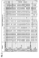
- FIG. 1 shows a layer system 1 according to the invention.
- the layer system 1 consists of a metallic substrate 4 which, in particular for components at high temperatures, consists of a nickel- or cobalt-based superalloy (US Pat. Fig. 2 ) consists.
- Remaining cobalt has or preferably off 27% - 29% Nickel, in particular 28% nickel, 23% - 25% Chrome, especially 24% chromium, 9% - 11% Aluminum, in particular 10% aluminum, 0.3% - 0.7% Yttrium, especially 0.6% yttrium and, Remaining cobalt has.
- the NiCoCrAlY bonding layer 7 consists of one of these compositions.
- An aluminum oxide layer has already formed on this metallic bonding layer 7 before the application of further ceramic layers. During operation, such an aluminum oxide layer (TGO) is formed.
- TGO aluminum oxide layer
- An inner ceramic layer 10 preferably a fully or partially stabilized zirconium oxide layer, is preferably present on the metallic bonding layer 7 or on the aluminum oxide layer (not illustrated).
- yttria-stabilized zirconia preferably with 6wt% - 8wt% yttrium is used.
- calcium oxide, ceria or hafnium oxide can be used to stabilize zirconia.
- the zirconium oxide is preferably applied as a plasma-sprayed layer, but can preferably also be applied as a columnar structure by means of electron beam evaporation (EBPVD).
- EBPVD electron beam evaporation
- an outer ceramic layer 13 is applied, which according to the invention comprises a mixed crystal of gadolinium, hafnium and zirconium with pyrochlore structure.
- Gadolinium (Gd) for A hafnium and zirconium (Hf, Zr) is used for B, which is a mixed crystal structure Gd v (Zr Hf X Y) O z. Again, small deviations from this stoichiometry may occur.
- the outer ceramic layer 13 also includes Gd v (Hf x zr y ) O 7 .
- the outer ceramic layer 13 comprises Gd 2 (Hf x Zr y ) O z .
- any mixing ratios y: x of zirconium and hafnium can be used.
- mixing ratios of 10:90, 20:80, 30:70 or 40:60 are preferably used for hafnium to zirconium. It is also advantageous to use mixing ratios of 50:50, 60:40, 70:30, 80:20 or 90:10 for hafnium to zirconium.
- the layer may be made of a powder which gives the proportions of the above composition.
- the mixed crystals can also be produced during the coating process or by a heat treatment after the coating process.
- the layer thickness of the inner layer 10 is preferably between 10% and 50% of the total layer thickness D of inner layer 10 and outer layer 13.
- the layer thickness of the inner layer 10 is between 10% and 40% or between 10% and 30% of the total layer thickness.
- the layer thickness of the inner layer 10 has 10% to 20% of the total layer thickness. It is likewise preferred if the layer thickness of the inner layer 10 is between 20% and 50% or between 20% and 40% of the total layer thickness.
- the layer thickness of the inner layer 10 is 30% to 50% of the total layer thickness.
- the layer thickness of the inner layer 10 has 30% to 40% of the total layer thickness. It is likewise preferred if the layer thickness of the inner layer 10 is between 40% and 50% of the total layer thickness.
- the pyrochlore phase has better thermal insulation properties than the ZrO 2 layer
- the ZrO 2 layer can be made as thick as the pyrochlore phase.
- the inner ceramic layer 10 preferably has a thickness of 40 ⁇ m to 60 ⁇ m, in particular 50 ⁇ m ⁇ 10%.
- the total layer thickness of the inner layer 10 and the outer layer 13 is preferably 300 ⁇ m or preferably 400 ⁇ m.
- the maximum total layer thickness is advantageously 800 ⁇ m or preferably a maximum of 600 ⁇ m.
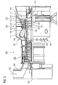
- FIG. 3 shows by way of example a gas turbine 100 in a longitudinal partial section.
- the gas turbine 100 has inside a rotatably mounted about a rotation axis 102 rotor 103 with a shaft 101, which is also referred to as a turbine runner.
- an intake housing 104 a compressor 105, for example, a toroidal combustion chamber 110, in particular annular combustion chamber, with a plurality of coaxially arranged burners 107, a turbine 108 and the exhaust housing 109th
- a compressor 105 for example, a toroidal combustion chamber 110, in particular annular combustion chamber, with a plurality of coaxially arranged burners 107, a turbine 108 and the exhaust housing 109th
- the annular combustion chamber 110 communicates with an annular annular hot gas channel 111, for example.
- annular annular hot gas channel 111 for example.
- turbine stages 112 connected in series form the turbine 108.
- Each turbine stage 112 is formed, for example, from two blade rings. As seen in the direction of flow of a working medium 113, in the hot gas channel 111 of a row of guide vanes 115, a series 125 formed of rotor blades 120 follows.
- the guide vanes 130 are fastened to an inner housing 138 of a stator 143, whereas the moving blades 120 of a row 125 are attached to the rotor 103 by means of a turbine disk 133, for example.
- air 105 is sucked in and compressed by the compressor 105 through the intake housing 104.
- the compressed air provided at the turbine-side end of the compressor 105 is supplied to the burners 107 where it is mixed with a fuel.
- the mixture is then burned to form the working fluid 113 in the combustion chamber 110.
- the working medium 113 flows along the hot gas channel 111 past the guide vanes 130 and the rotor blades 120.
- the working medium 113 expands in a pulse-transmitting manner so that the rotor blades 120 drive the rotor 103 and drive the machine coupled to it.
- the components exposed to the hot working medium 113 are subject to thermal loads during operation of the gas turbine 100.
- the guide vanes 130 and rotor blades 120 of the first turbine stage 112, viewed in the flow direction of the working medium 113, are subjected to the greatest thermal stress in addition to the heat shield elements lining the annular combustion chamber 110.
- substrates of the components may have a directional structure, i. they are monocrystalline (SX structure) or have only longitudinal grains (DS structure).
- iron-, nickel- or cobalt-based superalloys are used as the material for the components, in particular for the turbine blade 120, 130 and components of the combustion chamber 110.
- Such superalloys are for example from EP 1 204 776 B1 .
- EP 1 306 454 .
- the vane 130 has a guide vane foot (not shown here) facing the inner casing 138 of the turbine 108 and a vane head opposite the vane root.
- the vane head faces the rotor 103 and fixed to a mounting ring 140 of the stator 143.
- FIG. 4 shows a perspective view of a blade 120 or guide vane 130 of a turbomachine, which extends along a longitudinal axis 121.
- the turbomachine may be a gas turbine of an aircraft or a power plant for power generation, a steam turbine or a compressor.
- the blade 120, 130 has along the longitudinal axis 121 consecutively a fastening region 400, a blade platform 403 adjacent thereto and an airfoil 406 and a blade tip 415.
- the blade 130 may have at its blade tip 415 another platform (not shown).
- a blade root 183 is formed, which serves for attachment of the blades 120, 130 to a shaft or a disc (not shown).
- the blade root 183 is designed, for example, as a hammer head. Other designs as Christmas tree or Schwalbenschwanzfuß are possible.
- the blade 120, 130 has a leading edge 409 and a trailing edge 412 for a medium flowing past the airfoil 406.
- Such superalloys are for example from EP 1 204 776 B1 .
- EP 1 306 454 .
- the blade 120, 130 can be made by a casting process, also by directional solidification, by a forging process, by a milling process or combinations thereof.
- Workpieces with a monocrystalline structure or structures are used as components for machines which are exposed to high mechanical, thermal and / or chemical stresses during operation.
- Such monocrystalline workpieces takes place e.g. by directed solidification from the melt.
- These are casting processes in which the liquid metallic alloy is transformed into a monocrystalline structure, i. to the single-crystal workpiece, or directionally solidified.
- dendritic crystals are aligned along the heat flow and form either a columnar grain structure (columnar, ie grains that run the entire length of the workpiece and here, in common parlance, referred to as directionally solidified) or a monocrystalline structure, ie the whole Workpiece exists from a single crystal.
- directionally solidified columnar grain structure
- monocrystalline structure ie the whole Workpiece exists from a single crystal.
- directionally solidified microstructures which means both single crystals that have no grain boundaries or at most small angle grain boundaries, and stem crystal structures that have probably longitudinal grain boundaries but no transverse grain boundaries. These second-mentioned crystalline structures are also known as directionally solidified structures.
- the blades 120, 130 may have coatings against corrosion or oxidation, e.g. M is at least one element of the group iron (Fe), cobalt (Co), nickel (Ni), X is an active element and stands for yttrium (Y) and / or silicon and / or at least one element of the rare ones Earth, or hafnium (Hf)).
- M is at least one element of the group iron (Fe), cobalt (Co), nickel (Ni)
- X is an active element and stands for yttrium (Y) and / or silicon and / or at least one element of the rare ones Earth, or hafnium (Hf)).
- Such alloys are known from the EP 0 486 489 B1 .
- EP 0 412 397 B1 or EP 1 306 454 A1 are known from the EP 0 486 489 B1 .
- the density is preferably 95% of the theoretical density.
- thermal barrier coating which is preferably the outermost layer, and consists of the layer system 1 according to the invention.
- the thermal barrier coating covers the entire MCrAlX layer.
- Electron beam evaporation produces stalk-shaped grains in the thermal barrier coating.
- the thermal barrier coating may have porous, micro- or macro-cracked grains for better thermal shock resistance.
- the thermal barrier coating is therefore preferably more porous than the MCrAlX layer.
- the blade 120, 130 may be hollow or solid. If the blade 120, 130 is to be cooled, it is hollow and may still film cooling holes 418 (indicated by dashed lines) on.
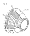
- the FIG. 5 shows a combustion chamber 110 of the gas turbine 100.
- the combustion chamber 110 is configured, for example, as a so-called annular combustion chamber, in which a plurality of circumferentially arranged around a rotation axis 102 around burners 107 open into a common combustion chamber space 154, the flames 156 produce.
- the combustion chamber 110 is configured in its entirety as an annular structure, which is positioned around the axis of rotation 102 around.
- the combustion chamber 110 is designed for a comparatively high temperature of the working medium M of about 1000 ° C to 1600 ° C.
- the combustion chamber wall 153 is provided on its side facing the working medium M side with an inner lining formed from heat shield elements 155.
- the heat shield elements 155 Due to the high temperatures inside the combustion chamber 110 may also be provided for the heat shield elements 155 and for their holding elements, a cooling system.
- the heat shield elements 155 are then hollow, for example, and may still have cooling holes (not shown) which open into the combustion chamber space 154.
- Each heat shield element 155 made of an alloy is equipped on the working medium side with a particularly heat-resistant protective layer (MCrAlX layer and / or ceramic coating) or is made of high-temperature-resistant material (solid ceramic blocks).
- M is at least one element of the group iron (Fe), cobalt (Co), nickel (Ni), X is an active element and stands for yttrium (Y) and / or silicon and / or at least one element of the rare earths, or hafnium (Hf).
- MCrAlX means: M is at least one element of the group iron (Fe), cobalt (Co), nickel (Ni), X is an active element and stands for yttrium (Y) and / or silicon and / or at least one element of the rare earths, or hafnium (Hf).
- Such alloys are known from the EP 0 486 489 B1 .
- EP 0 412 397 B1 or EP 1 306 454 A1 are known from the EP 0 486 489 B1 .
- EP 0 412 397 B1 or EP 1 306 454 A1 is known from the EP 0 486 489 B1 .
- MCrAlX On the MCrAlX can still be present, for example, a ceramic thermal barrier coating and consists and consists of the layer system 1 according to the invention.
- Electron beam evaporation produces stalk-shaped grains in the thermal barrier coating.
- thermal barrier coating may have porous, micro- or macro-cracked grains for better thermal shock resistance.
- Refurbishment means that turbine blades 120, 130, heat shield elements 155 may have to be freed from protective layers after their use (eg by sandblasting). This is followed by removal of the corrosion and / or oxidation layers or products. Optionally, cracks in the turbine blade 120, 130 or the heat shield element 155 are also repaired. Thereafter, a re-coating of the turbine blades 120, 130, heat shield elements 155 and a renewed use of the turbine blades 120, 130 or the heat shield elements 155.
Priority Applications (1)
| Application Number | Priority Date | Filing Date | Title |
|---|---|---|---|
| EP20100014408 EP2278040A3 (fr) | 2005-11-24 | 2006-10-17 | Système de revêtement contenant un phase pyrochlor mixte de gadolinium |
Applications Claiming Priority (3)
| Application Number | Priority Date | Filing Date | Title |
|---|---|---|---|
| EP20050025690 EP1790754A1 (fr) | 2005-11-24 | 2005-11-24 | Système de revêtement contenant un phase pyrochlor mixte de Gadolinium. |
| EP20100014408 EP2278040A3 (fr) | 2005-11-24 | 2006-10-17 | Système de revêtement contenant un phase pyrochlor mixte de gadolinium |
| EP06807343.6A EP1951928B1 (fr) | 2005-11-24 | 2006-10-17 | Système de revêtement contenant un phase pyrochlor mixte de gadolinium. |
Related Parent Applications (2)
| Application Number | Title | Priority Date | Filing Date |
|---|---|---|---|
| EP06807343.6A Division-Into EP1951928B1 (fr) | 2005-11-24 | 2006-10-17 | Système de revêtement contenant un phase pyrochlor mixte de gadolinium. |
| EP06807343.6 Division | 2006-10-17 |
Publications (2)
| Publication Number | Publication Date |
|---|---|
| EP2278040A2 true EP2278040A2 (fr) | 2011-01-26 |
| EP2278040A3 EP2278040A3 (fr) | 2012-03-28 |
Family
ID=36129771
Family Applications (4)
| Application Number | Title | Priority Date | Filing Date |
|---|---|---|---|
| EP20050025690 Withdrawn EP1790754A1 (fr) | 2005-11-24 | 2005-11-24 | Système de revêtement contenant un phase pyrochlor mixte de Gadolinium. |
| EP20100014407 Withdrawn EP2278039A3 (fr) | 2005-11-24 | 2006-10-17 | Système de revêtement contenant un phase pyrochlor mixte de gadolinium |
| EP20100014408 Withdrawn EP2278040A3 (fr) | 2005-11-24 | 2006-10-17 | Système de revêtement contenant un phase pyrochlor mixte de gadolinium |
| EP06807343.6A Active EP1951928B1 (fr) | 2005-11-24 | 2006-10-17 | Système de revêtement contenant un phase pyrochlor mixte de gadolinium. |
Family Applications Before (2)
| Application Number | Title | Priority Date | Filing Date |
|---|---|---|---|
| EP20050025690 Withdrawn EP1790754A1 (fr) | 2005-11-24 | 2005-11-24 | Système de revêtement contenant un phase pyrochlor mixte de Gadolinium. |
| EP20100014407 Withdrawn EP2278039A3 (fr) | 2005-11-24 | 2006-10-17 | Système de revêtement contenant un phase pyrochlor mixte de gadolinium |
Family Applications After (1)
| Application Number | Title | Priority Date | Filing Date |
|---|---|---|---|
| EP06807343.6A Active EP1951928B1 (fr) | 2005-11-24 | 2006-10-17 | Système de revêtement contenant un phase pyrochlor mixte de gadolinium. |
Country Status (10)
| Country | Link |
|---|---|
| US (1) | US9611551B2 (fr) |
| EP (4) | EP1790754A1 (fr) |
| JP (1) | JP2009517241A (fr) |
| CN (1) | CN101313080B (fr) |
| CA (1) | CA2630690C (fr) |
| FR (1) | FR2895742B1 (fr) |
| GB (1) | GB2432591B (fr) |
| IT (1) | ITMI20062223A1 (fr) |
| RU (1) | RU2392349C2 (fr) |
| WO (1) | WO2007060062A1 (fr) |
Cited By (1)
| Publication number | Priority date | Publication date | Assignee | Title |
|---|---|---|---|---|
| DE102015206321A1 (de) * | 2015-04-09 | 2016-10-13 | Siemens Aktiengesellschaft | Zweilagige keramische Wärmedämmschicht mit Übergangszone |
Families Citing this family (16)
| Publication number | Priority date | Publication date | Assignee | Title |
|---|---|---|---|---|
| DE502007006989D1 (de) * | 2007-05-07 | 2011-06-01 | Siemens Ag | Keramisches Pulver, keramische Schicht und Schichtsystem mit einer Gadolinium-Mischkristall-Pyrochlorphase und Oxiden |
| ATE530505T1 (de) | 2007-05-07 | 2011-11-15 | Siemens Ag | Keramisches pulver, keramische schicht sowie schichtsystem aus zwei pyrochlorphasen und oxiden |
| DE502007005837D1 (de) * | 2007-05-07 | 2011-01-13 | Siemens Ag | Zweilagiges Schichtsystem mit Pyrochlorphase und Oxiden |
| JP5647762B2 (ja) | 2007-05-07 | 2015-01-07 | シーメンス アクチエンゲゼルシヤフトSiemens Aktiengesellschaft | パイロクロア相と二次酸化物とを有する外側セラミック層を含有してなる層組織 |
| US20110033284A1 (en) * | 2009-08-04 | 2011-02-10 | United Technologies Corporation | Structurally diverse thermal barrier coatings |
| CN102666696B (zh) * | 2009-09-30 | 2014-10-29 | 陶氏环球技术有限责任公司 | 乙酰基化的甘油酯和它们与环氧化的脂肪酸酯的共混物 |
| EP2450465A1 (fr) * | 2010-11-09 | 2012-05-09 | Siemens Aktiengesellschaft | Système de couche poreux doté d'une couche intérieure poreuse |
| RU2532646C1 (ru) * | 2013-06-28 | 2014-11-10 | Фонд поддержки научной, научно-технической и инновационной деятельности "Энергия без границ" (Фонд "Энергия без границ") | Многослойное теплозащитное покрытие |
| FR3014477B1 (fr) * | 2013-12-06 | 2016-01-08 | Turbomeca | Rotor a aubes |
| US20170101874A1 (en) * | 2015-10-12 | 2017-04-13 | United Technologies Corporation | Multi-layered coating with columnar microstructure and branched columnar microstructure |
| US20180290929A1 (en) * | 2017-04-07 | 2018-10-11 | General Electric Company | Thermal Barrier System with Thin Dense Columnar TBC Layer and Methods of Forming the Same |
| RU2674292C1 (ru) * | 2017-06-19 | 2018-12-06 | Общество с ограниченной ответственностью "Термоэмиссионные Турбины" | Гиперзвуковой турбореактивный двигатель |
| CN111978087B (zh) * | 2019-05-22 | 2022-04-15 | 北京理工大学 | 一种复合材料及其制备方法和应用 |
| RU2714345C1 (ru) * | 2019-06-21 | 2020-02-14 | Государственный научный центр Российской Федерации - федеральное государственное унитарное предприятие "Исследовательский Центр имени М.В. Келдыша" | Способ получения градиентного нанокомпозитного теплозащитного покрытия |
| RU2746196C1 (ru) * | 2020-06-01 | 2021-04-08 | Общество С Ограниченной Ответственностью "Технологические Системы Защитных Покрытий" (Ооо "Тсзп") | Деталь и сборочная единица соплового аппарата турбины высокого давления |
| RU2763953C1 (ru) * | 2021-03-11 | 2022-01-11 | Российская Федерация, от имени которой выступает Государственная корпорация по атомной энергии "Росатом" (Госкорпорация "Росатом") | Комбинированное защитное покрытие |
Citations (12)
| Publication number | Priority date | Publication date | Assignee | Title |
|---|---|---|---|---|
| EP0486489B1 (fr) | 1989-08-10 | 1994-11-02 | Siemens Aktiengesellschaft | Revetement anticorrosion resistant aux temperatures elevees, notamment pour elements de turbines a gaz |
| EP0412397B1 (fr) | 1989-08-10 | 1998-03-25 | Siemens Aktiengesellschaft | Revêtement protecteur contenant du rhénium possédant une résistance plus grande à la corrosion et l'oxydation |
| EP0892090A1 (fr) | 1997-02-24 | 1999-01-20 | Sulzer Innotec Ag | Procédé de fabrication de structure smonocristallines |
| EP0786017B1 (fr) | 1994-10-14 | 1999-03-24 | Siemens Aktiengesellschaft | Couche de protection de pieces contre la corrosion, l'oxydation et les contraintes thermiques excessives, et son procede de production |
| WO1999067435A1 (fr) | 1998-06-23 | 1999-12-29 | Siemens Aktiengesellschaft | Alliage a solidification directionnelle a resistance transversale a la rupture amelioree |
| US6024792A (en) | 1997-02-24 | 2000-02-15 | Sulzer Innotec Ag | Method for producing monocrystalline structures |
| EP0992603A1 (fr) | 1998-10-01 | 2000-04-12 | United Technologies Corporation | Systèmes de revêtement de barrière thermique et matériaux |
| WO2000044949A1 (fr) | 1999-01-28 | 2000-08-03 | Siemens Aktiengesellschaft | Superalliage a base de nickel presentant une bonne usinabilite |
| EP0944746B1 (fr) | 1996-12-10 | 2001-07-04 | Siemens Aktiengesellschaft | Produit pouvant etre expose a un gaz chaud, pourvu d'une couche calorifuge, et son procede de production |
| EP1306454A1 (fr) | 2001-10-24 | 2003-05-02 | Siemens Aktiengesellschaft | Revêtement protecteur contenant du rhénium pour la protection d'un élément contre l'oxydation et la corrosion aux températures élevées |
| EP1319729A1 (fr) | 2001-12-13 | 2003-06-18 | Siemens Aktiengesellschaft | Pièce résistante à des températures élevées réalisé en superalliage polycristallin ou monocristallin à base de nickel |
| EP1204776B1 (fr) | 1999-07-29 | 2004-06-02 | Siemens Aktiengesellschaft | Piece resistant a des temperatures elevees et son procede de production |
Family Cites Families (19)
| Publication number | Priority date | Publication date | Assignee | Title |
|---|---|---|---|---|
| US4034142A (en) * | 1975-12-31 | 1977-07-05 | United Technologies Corporation | Superalloy base having a coating containing silicon for corrosion/oxidation protection |
| US4419416A (en) * | 1981-08-05 | 1983-12-06 | United Technologies Corporation | Overlay coatings for superalloys |
| JPH0541237A (ja) * | 1991-07-25 | 1993-02-19 | Nippon Telegr & Teleph Corp <Ntt> | 固体燃料電池 |
| JP2949605B2 (ja) * | 1991-09-20 | 1999-09-20 | 株式会社日立製作所 | 合金被覆ガスタービン翼及びその製造方法 |
| US6129991A (en) * | 1994-10-28 | 2000-10-10 | Howmet Research Corporation | Aluminide/MCrAlY coating system for superalloys |
| EP0713957A1 (fr) | 1994-11-25 | 1996-05-29 | FINMECCANICA S.p.A. AZIENDA ANSALDO | Méthode pour la réparation des couches protectives des aubes de turbine à gaz |
| US6258467B1 (en) * | 2000-08-17 | 2001-07-10 | Siemens Westinghouse Power Corporation | Thermal barrier coating having high phase stability |
| US6924040B2 (en) | 1996-12-12 | 2005-08-02 | United Technologies Corporation | Thermal barrier coating systems and materials |
| US6117560A (en) | 1996-12-12 | 2000-09-12 | United Technologies Corporation | Thermal barrier coating systems and materials |
| JP3413096B2 (ja) * | 1998-03-16 | 2003-06-03 | 株式会社東芝 | 耐熱部材およびその製造方法 |
| US20040180233A1 (en) * | 1998-04-29 | 2004-09-16 | Siemens Aktiengesellschaft | Product having a layer which protects against corrosion. and process for producing a layer which protects against corrosion |
| NZ500555A (en) * | 1999-08-02 | 2000-11-24 | Hovione Int Ltd | Process for the preparation of mometasone furoate |
| DE10158639A1 (de) | 2001-04-03 | 2002-10-17 | Forschungszentrum Juelich Gmbh | Wärmedämmschicht auf Basis von La2Zr2O7 für hohe Temperaturen |
| JP4166977B2 (ja) * | 2001-12-17 | 2008-10-15 | 三菱重工業株式会社 | 耐高温腐食合金材、遮熱コーティング材、タービン部材、及びガスタービン |
| DE10200803A1 (de) | 2002-01-11 | 2003-07-31 | Forschungszentrum Juelich Gmbh | Herstellung eines keramischen Werkstoffes für eine Wärmedämmschicht sowie eine den Werkstoff enthaltene Wärmedämmschicht |
| EP1380672A1 (fr) | 2002-07-09 | 2004-01-14 | Siemens Aktiengesellschaft | Composant à haute résistance contre l'oxydation |
| US6730422B2 (en) | 2002-08-21 | 2004-05-04 | United Technologies Corporation | Thermal barrier coatings with low thermal conductivity |
| US20060177676A1 (en) | 2003-08-13 | 2006-08-10 | Ulrich Bast | Heat-insulation material and arrangement of a heat-insulation layer containing said heat-insulation material |
| US7326470B2 (en) * | 2004-04-28 | 2008-02-05 | United Technologies Corporation | Thin 7YSZ, interfacial layer as cyclic durability (spallation) life enhancement for low conductivity TBCs |
-
2005
- 2005-11-24 EP EP20050025690 patent/EP1790754A1/fr not_active Withdrawn
-
2006
- 2006-10-17 EP EP20100014407 patent/EP2278039A3/fr not_active Withdrawn
- 2006-10-17 WO PCT/EP2006/067497 patent/WO2007060062A1/fr active Application Filing
- 2006-10-17 EP EP20100014408 patent/EP2278040A3/fr not_active Withdrawn
- 2006-10-17 CA CA2630690A patent/CA2630690C/fr not_active Expired - Fee Related
- 2006-10-17 US US12/085,399 patent/US9611551B2/en not_active Expired - Fee Related
- 2006-10-17 EP EP06807343.6A patent/EP1951928B1/fr active Active
- 2006-10-17 CN CN2006800440113A patent/CN101313080B/zh not_active Expired - Fee Related
- 2006-10-17 RU RU2008125430A patent/RU2392349C2/ru not_active IP Right Cessation
- 2006-10-17 JP JP2008541674A patent/JP2009517241A/ja active Pending
- 2006-11-16 FR FR0610020A patent/FR2895742B1/fr not_active Expired - Fee Related
- 2006-11-21 IT ITMI20062223 patent/ITMI20062223A1/it unknown
- 2006-11-22 GB GB0623305A patent/GB2432591B/en not_active Expired - Fee Related
Patent Citations (12)
| Publication number | Priority date | Publication date | Assignee | Title |
|---|---|---|---|---|
| EP0486489B1 (fr) | 1989-08-10 | 1994-11-02 | Siemens Aktiengesellschaft | Revetement anticorrosion resistant aux temperatures elevees, notamment pour elements de turbines a gaz |
| EP0412397B1 (fr) | 1989-08-10 | 1998-03-25 | Siemens Aktiengesellschaft | Revêtement protecteur contenant du rhénium possédant une résistance plus grande à la corrosion et l'oxydation |
| EP0786017B1 (fr) | 1994-10-14 | 1999-03-24 | Siemens Aktiengesellschaft | Couche de protection de pieces contre la corrosion, l'oxydation et les contraintes thermiques excessives, et son procede de production |
| EP0944746B1 (fr) | 1996-12-10 | 2001-07-04 | Siemens Aktiengesellschaft | Produit pouvant etre expose a un gaz chaud, pourvu d'une couche calorifuge, et son procede de production |
| EP0892090A1 (fr) | 1997-02-24 | 1999-01-20 | Sulzer Innotec Ag | Procédé de fabrication de structure smonocristallines |
| US6024792A (en) | 1997-02-24 | 2000-02-15 | Sulzer Innotec Ag | Method for producing monocrystalline structures |
| WO1999067435A1 (fr) | 1998-06-23 | 1999-12-29 | Siemens Aktiengesellschaft | Alliage a solidification directionnelle a resistance transversale a la rupture amelioree |
| EP0992603A1 (fr) | 1998-10-01 | 2000-04-12 | United Technologies Corporation | Systèmes de revêtement de barrière thermique et matériaux |
| WO2000044949A1 (fr) | 1999-01-28 | 2000-08-03 | Siemens Aktiengesellschaft | Superalliage a base de nickel presentant une bonne usinabilite |
| EP1204776B1 (fr) | 1999-07-29 | 2004-06-02 | Siemens Aktiengesellschaft | Piece resistant a des temperatures elevees et son procede de production |
| EP1306454A1 (fr) | 2001-10-24 | 2003-05-02 | Siemens Aktiengesellschaft | Revêtement protecteur contenant du rhénium pour la protection d'un élément contre l'oxydation et la corrosion aux températures élevées |
| EP1319729A1 (fr) | 2001-12-13 | 2003-06-18 | Siemens Aktiengesellschaft | Pièce résistante à des températures élevées réalisé en superalliage polycristallin ou monocristallin à base de nickel |
Cited By (1)
| Publication number | Priority date | Publication date | Assignee | Title |
|---|---|---|---|---|
| DE102015206321A1 (de) * | 2015-04-09 | 2016-10-13 | Siemens Aktiengesellschaft | Zweilagige keramische Wärmedämmschicht mit Übergangszone |
Also Published As
| Publication number | Publication date |
|---|---|
| US20090162648A1 (en) | 2009-06-25 |
| CN101313080B (zh) | 2011-10-19 |
| GB2432591A (en) | 2007-05-30 |
| EP2278040A3 (fr) | 2012-03-28 |
| JP2009517241A (ja) | 2009-04-30 |
| EP2278039A3 (fr) | 2012-03-28 |
| EP2278039A2 (fr) | 2011-01-26 |
| EP1951928A1 (fr) | 2008-08-06 |
| ITMI20062223A1 (it) | 2007-05-25 |
| WO2007060062A1 (fr) | 2007-05-31 |
| CN101313080A (zh) | 2008-11-26 |
| FR2895742B1 (fr) | 2010-11-05 |
| EP1951928B1 (fr) | 2017-03-29 |
| CA2630690C (fr) | 2011-05-10 |
| EP1790754A1 (fr) | 2007-05-30 |
| RU2008125430A (ru) | 2009-12-27 |
| FR2895742A1 (fr) | 2007-07-06 |
| WO2007060062A8 (fr) | 2007-07-12 |
| GB0623305D0 (en) | 2007-01-03 |
| CA2630690A1 (fr) | 2007-05-31 |
| RU2392349C2 (ru) | 2010-06-20 |
| US9611551B2 (en) | 2017-04-04 |
| GB2432591B (en) | 2011-05-18 |
Similar Documents
| Publication | Publication Date | Title |
|---|---|---|
| EP1951928B1 (fr) | Système de revêtement contenant un phase pyrochlor mixte de gadolinium. | |
| EP1971705B1 (fr) | Systeme de couches comportant deux phases pyrochlore | |
| EP1954854B1 (fr) | Revêtement de barrière thermique en deux couches contenant une phase pyrochlore | |
| EP1990327B1 (fr) | Poudre céramique, couche céramique et système de couche comportant une solution solide de phase structure pyrochlore à base de gadolinium et des oxydes | |
| EP1707653B1 (fr) | Système de revêtement | |
| EP1990330B1 (fr) | Poudre céramique, couche céramique et système de couche comportant une phrase pyrochlore et des oxydes | |
| EP1990328B1 (fr) | Poudre céramique, couche céramique tout comme système de couche comportant deux phrases pyrochlores et des oxydes | |
| EP2576853B1 (fr) | Alliage, couche de protection et composant | |
| EP2695971A1 (fr) | Système de couche à double couche poreux doté d'une phase pyrochlore | |
| EP2458025B1 (fr) | Alliage, couche de protection et composant | |
| EP1990329B1 (fr) | Système de couche à double épaisseur comportant une phase pyrochlore et des oxydes | |
| EP1793008A1 (fr) | Alliage, couche protectrice pour proteger un élément structurel contre la corrosion et l'oxydation aux temperatures hautes et élément structurel | |
| EP1798299B1 (fr) | Alliage, couche de protection et élément de construction | |
| EP1806418A1 (fr) | Alliage, couche protectrice pour proteger un élément structurel contre la corrosion et l'oxydation aux temperatures hautes et élément structurel | |
| DE202006009603U1 (de) | Zweilagiges Schichtsystem mit Pyrochlor-Phase | |
| DE202006009527U1 (de) | Schichtsystem mit zwei Pyrochlorphasen | |
| DE202006009526U1 (de) | Schichtsystem mit Gadolinium-Mischkristall-Pyrochlorphase | |
| EP2557201A1 (fr) | Alliage, couche de protection et composant | |
| EP2611949B1 (fr) | Alliage a base nickel, couche de protection et élément de construction | |
| EP2661370B1 (fr) | Alliage, couche protectrice et pièce | |
| EP1790746B1 (fr) | Alliage, couche de protection et composant | |
| EP1806419B1 (fr) | Alliage, couche protectrice pour proteger un élément structurel contre la corrosion et l'oxydation aux temperatures hautes, et élément structurel | |
| EP2568054A1 (fr) | Alliage, couche de protection et composant | |
| EP2345748A1 (fr) | Alliage, couche de protection et composant | |
| EP2354260A1 (fr) | Alliage, couche de protection et composant |
Legal Events
| Date | Code | Title | Description |
|---|---|---|---|
| PUAI | Public reference made under article 153(3) epc to a published international application that has entered the european phase |
Free format text: ORIGINAL CODE: 0009012 |
|
| AC | Divisional application: reference to earlier application |
Ref document number: 1951928 Country of ref document: EP Kind code of ref document: P |
|
| AK | Designated contracting states |
Kind code of ref document: A2 Designated state(s): AT BE BG CH CY CZ DE DK EE ES FI FR GB GR HU IE IS IT LI LT LU LV MC NL PL PT RO SE SI SK TR |
|
| AX | Request for extension of the european patent |
Extension state: AL BA HR MK RS |
|
| PUAL | Search report despatched |
Free format text: ORIGINAL CODE: 0009013 |
|
| AK | Designated contracting states |
Kind code of ref document: A3 Designated state(s): AT BE BG CH CY CZ DE DK EE ES FI FR GB GR HU IE IS IT LI LT LU LV MC NL PL PT RO SE SI SK TR |
|
| AX | Request for extension of the european patent |
Extension state: AL BA HR MK RS |
|
| RIC1 | Information provided on ipc code assigned before grant |
Ipc: C23C 30/00 20060101ALI20120221BHEP Ipc: C23C 28/00 20060101ALI20120221BHEP Ipc: C23C 4/10 20060101ALI20120221BHEP Ipc: C23C 14/08 20060101AFI20120221BHEP |
|
| STAA | Information on the status of an ep patent application or granted ep patent |
Free format text: STATUS: THE APPLICATION IS DEEMED TO BE WITHDRAWN |
|
| RAP1 | Party data changed (applicant data changed or rights of an application transferred) |
Owner name: SIEMENS AKTIENGESELLSCHAFT |
|
| 18D | Application deemed to be withdrawn |
Effective date: 20120929 |