EP2276960B1 - Joining and connecting device for high-pressure lines - Google Patents
Joining and connecting device for high-pressure lines Download PDFInfo
- Publication number
- EP2276960B1 EP2276960B1 EP08846210.6A EP08846210A EP2276960B1 EP 2276960 B1 EP2276960 B1 EP 2276960B1 EP 08846210 A EP08846210 A EP 08846210A EP 2276960 B1 EP2276960 B1 EP 2276960B1
- Authority
- EP
- European Patent Office
- Prior art keywords
- hose
- joining
- connecting device
- half shells
- sleeve
- Prior art date
- Legal status (The legal status is an assumption and is not a legal conclusion. Google has not performed a legal analysis and makes no representation as to the accuracy of the status listed.)
- Active
Links
- 230000001681 protective effect Effects 0.000 claims description 57
- 210000002445 nipple Anatomy 0.000 claims description 35
- 238000006073 displacement reaction Methods 0.000 claims description 8
- 239000000463 material Substances 0.000 claims description 2
- 229920003266 Leaf® Polymers 0.000 claims 1
- 230000036316 preload Effects 0.000 claims 1
- 230000006835 compression Effects 0.000 description 10
- 238000007906 compression Methods 0.000 description 10
- 230000006870 function Effects 0.000 description 4
- 238000007789 sealing Methods 0.000 description 3
- 230000008901 benefit Effects 0.000 description 2
- 230000015572 biosynthetic process Effects 0.000 description 2
- 238000010276 construction Methods 0.000 description 2
- 230000009993 protective function Effects 0.000 description 2
- 230000009471 action Effects 0.000 description 1
- 239000002131 composite material Substances 0.000 description 1
- 150000001875 compounds Chemical class 0.000 description 1
- 230000008878 coupling Effects 0.000 description 1
- 238000010168 coupling process Methods 0.000 description 1
- 238000005859 coupling reaction Methods 0.000 description 1
- 230000001419 dependent effect Effects 0.000 description 1
- 230000000694 effects Effects 0.000 description 1
- 238000012986 modification Methods 0.000 description 1
- 230000004048 modification Effects 0.000 description 1
- 238000011084 recovery Methods 0.000 description 1
- 239000007787 solid Substances 0.000 description 1
Images


Classifications
-
- F—MECHANICAL ENGINEERING; LIGHTING; HEATING; WEAPONS; BLASTING
- F16—ENGINEERING ELEMENTS AND UNITS; GENERAL MEASURES FOR PRODUCING AND MAINTAINING EFFECTIVE FUNCTIONING OF MACHINES OR INSTALLATIONS; THERMAL INSULATION IN GENERAL
- F16L—PIPES; JOINTS OR FITTINGS FOR PIPES; SUPPORTS FOR PIPES, CABLES OR PROTECTIVE TUBING; MEANS FOR THERMAL INSULATION IN GENERAL
- F16L33/00—Arrangements for connecting hoses to rigid members; Rigid hose connectors, i.e. single members engaging both hoses
- F16L33/20—Undivided rings, sleeves or like members contracted on the hose or expanded in the hose by means of tools; Arrangements using such members
- F16L33/207—Undivided rings, sleeves or like members contracted on the hose or expanded in the hose by means of tools; Arrangements using such members only a sleeve being contracted on the hose
- F16L33/2071—Undivided rings, sleeves or like members contracted on the hose or expanded in the hose by means of tools; Arrangements using such members only a sleeve being contracted on the hose the sleeve being a separate connecting member
- F16L33/2073—Undivided rings, sleeves or like members contracted on the hose or expanded in the hose by means of tools; Arrangements using such members only a sleeve being contracted on the hose the sleeve being a separate connecting member directly connected to the rigid member
- F16L33/2076—Undivided rings, sleeves or like members contracted on the hose or expanded in the hose by means of tools; Arrangements using such members only a sleeve being contracted on the hose the sleeve being a separate connecting member directly connected to the rigid member by plastic deformation
-
- F—MECHANICAL ENGINEERING; LIGHTING; HEATING; WEAPONS; BLASTING
- F16—ENGINEERING ELEMENTS AND UNITS; GENERAL MEASURES FOR PRODUCING AND MAINTAINING EFFECTIVE FUNCTIONING OF MACHINES OR INSTALLATIONS; THERMAL INSULATION IN GENERAL
- F16L—PIPES; JOINTS OR FITTINGS FOR PIPES; SUPPORTS FOR PIPES, CABLES OR PROTECTIVE TUBING; MEANS FOR THERMAL INSULATION IN GENERAL
- F16L33/00—Arrangements for connecting hoses to rigid members; Rigid hose connectors, i.e. single members engaging both hoses
- F16L33/20—Undivided rings, sleeves or like members contracted on the hose or expanded in the hose by means of tools; Arrangements using such members
- F16L33/207—Undivided rings, sleeves or like members contracted on the hose or expanded in the hose by means of tools; Arrangements using such members only a sleeve being contracted on the hose
- F16L33/2071—Undivided rings, sleeves or like members contracted on the hose or expanded in the hose by means of tools; Arrangements using such members only a sleeve being contracted on the hose the sleeve being a separate connecting member
- F16L33/2073—Undivided rings, sleeves or like members contracted on the hose or expanded in the hose by means of tools; Arrangements using such members only a sleeve being contracted on the hose the sleeve being a separate connecting member directly connected to the rigid member
-
- F—MECHANICAL ENGINEERING; LIGHTING; HEATING; WEAPONS; BLASTING
- F16—ENGINEERING ELEMENTS AND UNITS; GENERAL MEASURES FOR PRODUCING AND MAINTAINING EFFECTIVE FUNCTIONING OF MACHINES OR INSTALLATIONS; THERMAL INSULATION IN GENERAL
- F16L—PIPES; JOINTS OR FITTINGS FOR PIPES; SUPPORTS FOR PIPES, CABLES OR PROTECTIVE TUBING; MEANS FOR THERMAL INSULATION IN GENERAL
- F16L37/00—Couplings of the quick-acting type
- F16L37/08—Couplings of the quick-acting type in which the connection between abutting or axially overlapping ends is maintained by locking members
- F16L37/12—Couplings of the quick-acting type in which the connection between abutting or axially overlapping ends is maintained by locking members using hooks, pawls or other movable or insertable locking members
- F16L37/1225—Couplings of the quick-acting type in which the connection between abutting or axially overlapping ends is maintained by locking members using hooks, pawls or other movable or insertable locking members using a retaining member the extremities of which, e.g. in the form of a U, engage behind a shoulder of both parts
Definitions
- the invention relates to a connecting and connecting device for high pressure lines for connecting a hose to another hose or to a high pressure working device, wherein the end of the hose is provided with a hose fitting consisting of a nipple insertable into the inner core of a hose body and on the outside of Tubular body patch, connectable to the nipple and aufpressbaren on the hose body sleeve, said connected to the hose body hose fitting has a radially projecting flange and protruding from the hose body end of the nipple has a patch on its outer periphery seal and together with the seal in a receiving socket is inserted and the receiving socket and the radially projecting flange of two receiving socket and flange outside comprehensive half-shells are included as connecting and connecting device and wherein egg ne the inclusion of the flange ring serving recess in the half-shells is dimensioned such that an axial movement of the hose end attached thereto hose fitting between
- connection and connection device with the aforementioned features is in the EP 0 836 043 A1 described, with the hose fittings known from the aforementioned document can be used with a nipple for connection to the corresponding hose fittings other hoses or with a working device.
- a secure locking of the connection and connection device by the action of the hose with the corresponding high pressure is already effected by axially displacing the corresponding flange of the tubing in the space enclosed by the half-shells in a positive engagement with the half-shells is such that the half-shells can no longer be removed from the pressurized hose fitting.
- connection and connection device A disassembly of the connection and connection device, however, is possible in a simple manner in a depressurized state, because then the hose fitting in question is far enough to move inside the half shells until the flange comes out of engagement with the half shells and they can be removed to the outside.
- connection and connection device With the known connection and connection device, the disadvantage of an axially projecting structure is still connected, because the required for the connection of the nipple with the hose body outer compression sleeve is clearly spaced from the coupling of the two nipples of the hose ends to be joined together causing half shells.
- connection and connection device with the generic features such that it has a more compact construction in the axial direction.
- the invention provides that, in addition to the receiving bushing and the flange ring, the two half shells comprise a section of the outer sleeve adjoining the flange ring on the outside.
- the invention has the advantage that by incorporating at least one outer sleeve into the connection and connection device, an axially compact construction of the connection and connection device is realized.
- the flange engages with a projection projecting axially in the direction of the hose body into a groove formed in the half shells as a receiving configuration.
- the flange is attached to the front end of the sleeve, wherein the flange can be integral part of the sleeve.
- the flange ring is attached to a projecting from the hose body portion of the nipple between the sleeve and the receiving socket.
- the flange can for example be welded to the nipple or attached in any other way.
- the receiving bushing has a length such that the seal having the front end of the nipple is located both in the release position and in the locking position in the interior of the receiving socket, thus ensuring that in any position the hose fitting is provided within the receiving space enclosed by the half-shells a secure seal of the nipple against the receiving socket.
- the two receiving sleeve and flange are encompassing half-shells held together by means of a patch on its outer circumference bent spring clip in its closed position, wherein it can be provided that the half shells each have a confiscation for flush receiving the have curved spring clip. This ensures that the spring clips do not project beyond the outer circumference of the connection and connection device.
- the half-shells are held together in their closed position by means of U-shaped spring plugs inserted radially at their outer ends.
- the half-shells are held together in their closed position by means of an external hinge. It can be provided in a development that the half-shells are each supported in their closed position biasing and connected to the half-shells spring leaves on the hinge axis of the hinge.
- a further embodiment of the invention may be provided to hold the two half-shells turn a curved spring clip, which is supported with its one end to the hinge axis of a correspondingly provided hinge.
- This hinge axis can be attached to the two half shells by means of each attached, preferably so welded hinge straps be set.
- the receiving socket is positively encompassed by the half-shells and fixed therein axially immovable.
- connection and connection device for connecting two hose lines
- the half shells surround the flange rings of the two hose fittings of the hose lines to be connected including the interposed receiving socket with the nipples inserted therein and hold each other.
- the corresponding connection is realized in that the receiving socket connected to the working device and the half shells are fixed axially immovable in its closed position on the receiving socket or on the implement.
- a further embodiment of the invention for connecting a hose again to a high-pressure working device or to a standardized screw having further hose provided that the receiving socket is formed as connectable to the implement or the screw adapter, now the corresponding flange on the front end of the adapter, preferably in one piece, is formed, wherein the flange attached to the adapter flange is encompassed by the half-shells together with the flange of the hose fitting connected to the hose to be connected.
- an external thread for screwing the adapter into a connection formed for example on a working device or alternatively an internal thread for connecting the standardized screw connection of a hose line may be formed.
- a detachably mounted on the hose fitting cap for covering the open end of the hose fitting is provided, and the hat-shaped cap a protective area for axial enclosing attaching to the open end of the hose fitting and an axially adjacent to the protection area Holding portion having an outwardly bulging wall portion for radially attaching the protective cap on the outer periphery of a portion of the sleeve of the hose fitting.
- the protection area consists of an inside of the closed lid portion projecting approach to plugging on the end of the hose fitting, wherein the holding function of the cap can be realized by the outwardly bulging wall portions of the cap resiliently formed are.
- connection and connection device with a protective cap fixed thereto is according to one embodiment provided that after the assembly of the hose fitting plugged thereon protective cap is also used to form an additional safeguard against loosening the connection and connection device, wherein it is provided that the hat-shaped cap arranged by means of one on the inside of their wall areas and in a formed on the outside of the sleeve groove engaging projection axially fixed in its plugged onto the hose fitting position and the groove is arranged such that an axial displacement of the hose fitting with the attached thereto protective cap to the half shells out is excluded.
- connection and connection device Since it is necessary to release the connection and connection device, the relevant hose fitting to move axially into the interior of the half-shells in until the flange is disengaged from the half shells, by means of the plugged and axially fixed cap an additional backup of the connection and Connected device realized in its connection position, as far as the hose fitting in question is not axially displaceable.
- the additional arrangement of a protective hose pushed over the high-pressure hose on the outside can also be provided, such as such a protective hose in the WO 2006/002459 A1 is described.
- a problem is to attach the respective end of the protective tube in the area of the hose fitting or the connection and connection device, wherein the attachment of the protective tubes usually takes place in the nipple of the hose fittings.
- the protective tube can not fulfill its intended protective function in such a case.
- connection and connection device provides a convenient starting point, and thus is provided according to an embodiment of the invention that the high pressure line with the connected hose fitting outside comprehensive protective tube is provided with its associated end is pushed over the protruding from the half shells portion of the sleeve of the hose fitting and fixed thereto by means of an externally applied compression sleeve, and that the width of the protective cap and the position of the sleeve mounted on the compression sleeve are coordinated such that the protective cap between the Half shells and the compression sleeve can be used as an axial abutment such that an axial displacement of the hose fitting is excluded to the half shells out.
- the protective hose is fastened to the hose sleeve by means of a compression sleeve, which is applied in a manner known per se to the sleeve of the hose fitting.
- a compression sleeve which is applied in a manner known per se to the sleeve of the hose fitting.
- the protective tube consists of a flexible and stretchable material. This ensures that, in the event of an excessively high tensile force acting on the hose line, in each case the rigidly formed inner high-pressure hose first breaks and the flexible protective hose remains connected to the hose fitting.
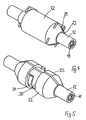
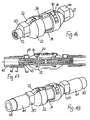
- FIG. 1 shows, two hose fittings 10 are connected by high-pressure hose lines not shown together.
- Each hose fitting 10 consists of a nipple 11 to be inserted into the inner core of a hose body, not shown, and an outer sleeve 12.
- Between nipple 11 and sleeve 12 is an annular space 13 for receiving the hose body, wherein on the outside of the nipple 11 as well as on the inside the sleeve 12 teeth 14 are formed, which dig in a compression of the sleeve 12 with the hose body in each case in the hose body and thereby establish a firm connection between the hose fitting 10 and the hose body.
- the nipple 11 has a further groove 17 for receiving a sealing ring 18 inserted therein. With this front end and the sealing ring 18 seated thereon, the two nipples 11 of the two hose fittings 10 to be connected are inserted from both sides into a centrally arranged receiving bushing 19 until the two nipples 11 abut one another at the front.
- the two sleeves 12 each have as an integral part of a radially projecting flange 20, which has a directed toward the hose fitting 10 projection 21 at its outer periphery.
- the two flange rings 20 together with an intermediate receiving bushing 19 are enclosed by two outer shells 22 placed on the outside, the half shells 22 still extending over a partial area of the respective sleeve 12 of the hose fitting 10.
- the two composite half-shells 22 form a receiving recess 23, which is adapted for fitting the flange ring 20 with projection 21 of the hose fitting 10.
- the receiving recess 23 has such an axial extent that the two flange rings 20 are axially displaceable therein by a certain amount, as will be explained.
- the two half-shells 22 each have a groove 25 for receiving the projection 21.
- FIG. 1 shows the output or mounting position of the connection and connection device in which the half-shells 22 are slipped outwardly around the two hose fittings 10 to be joined together and the receiving bushing 19 located therebetween, thereof in the in FIG. 1 shown position but can also be removed again, so that the connection of the two hose fittings is solvable.
- FIG. 2 now shows a further assembly step by the two hose fittings 10 are each displaced outwards until their located on the flange rings 20 projections 21 engage in the associated grooves 25 of the half-shells 22.
- the nipples 11 move apart, and there is a gap 26 in the interior of the receiving bushing 19.
- each of the axially acting in the gap 26 pressure leads to the pressing of the respective Projection 21 in the associated groove 25 of the half-shell 22, as shown in detail in FIG. 3 is shown.
- Projection 27 and recess 28 thus together form a lock for the outer half shells 22 with the sleeve 12 and the flange ring 20 such that in the pressed-pressed position, the half-shells 22 can not be opened to the outside.
- FIG. 4 shows FIG. 4 in a first embodiment, the arrangement of U-shaped spring plugs 29, which are each guided through the two half-shells 22, that the half-shells 22 are fixed to each other.
- FIG. 5 An alternative option is in FIG. 5 shown.
- FIGS. 6 and 7 represented by the two half-shells 22 are supported by means of an outer hinge axis 32 to each other.
- spring leaves 33 can be pivotally mounted, which in turn press with bias on the half-shells 22 and set them in the closed position.
- FIG. 8 shows an embodiment, which consists of a combination of in Figures 5 or 6 and 7 illustrated embodiments.
- the half-shells 22 are in turn held together by a pre-bent spring clip 31 arranged in a recess 30, one end of the spring clip 31 being pivotably supported on a correspondingly arranged hinge axis 32.
- the hinge axis 32 is held in each case attached to the two half-shells 22 by means of welds 41 hinge straps 40.
- connection and connection device can also be designed to define a mounted at the end of a high-pressure hose to be connected hose fitting 10 to a high-pressure working device, not shown.
- the receiving bushing 19 forms part of a terminal 34 of the working device, not shown, wherein the half-shells 22 engage with a formed at its axial end hook 36 in a formed on the outer periphery of the receiving bushing 19 groove 35.
- the half-shells 22 are in turn fixed axially immovable, so that they can serve as an abutment for the engagement of the flange 20 with projection 21, in particular to FIGS. 1 to 3 described.
- FIG. 10 illustrated embodiment differs from the in FIG. 9 illustrated embodiment in that the flange 20 with projection 21 is no longer located on the sleeve 12, but applied directly to the nipple 11 and fixedly connected to this, for example, is welded thereto.
- this other attachment of the flange 20 has no effect on the described function of the connection and connection device according to the invention.
- an adapter 45 which offers a connection option with its free end 47.
- the free end 47 of the adapter 45 with an external thread 46 may be formed for screwing the adapter into a connection formed on a working device.
- the adapter 45 comes in its encompassed by the half-shells 22 area at the same time the function of the receiving sleeve 19 in the previously described embodiments of the invention by the nipple 11 with the seated sealing ring 18 in the adapter 45 can be inserted.
- the front side of the adapter 45 preferably integrally the flange 20 is arranged with the engaging in the half-shells 22 projection 21, and insofar corresponds to the adapter 45 in its handling in the context of the connection and connection device to, for example FIGS. 1 to 3 described embodiment.
- a protective cap 50 It is customary to protect such hose fittings 10 at their free end prior to assembly by placing a protective cap, and in this respect includes the inventive connecting and connecting device according to FIG. 12
- a protective cap 50 This hat-shaped in a conventional manner cap 50 has, starting from its closed lid portion 52 a first protection area 51, with which the cap 50 on the nipple 11 of the hose assembly 10 can be plugged.
- the protection region 51 consists of an inside of the closed lid portion 52 projecting lug 53, which is adapted to be plugged onto the nipple 11 of the hose fitting 10.
- Axially to the protective area 21 includes a holding portion 54 which has bulged outward wall portions 55 of the protective cap 50, which are formed and arranged in a resilient embodiment so that the protective cap 50 after removal from the nipple 11 to the sleeve 12 of the hose fitting 10 attachable and thereby on the hose fitting 10 can be fixed.
- the protective cap 50 is held with the hose assembly mounted on the hose fitting 10 itself and is available in a further handling of the hose assembly 10 for a new protective function available, as from FIG. 13 seen.
- the protective cap 50 can according to the in the FIGS. 14 and 15 illustrated embodiment may be given a further function when the protective cap 50 is provided in the region of its bulged wall portions 55 with an inwardly projecting projection 56, which is assigned to a formed on the outer circumference of the sleeve 12 of the hose assembly 10 groove 57.
- the protective cap 50 When plugged onto the sleeve 12 protective cap 50, the protective cap 50 is fixed axially immovably on the hose assembly 10 upon engagement of the projection 56 in the groove 57.
- the groove 57 is arranged on the sleeve 12 in each case such that an axial displacement of the hose fitting 10 with the protective cap 50 plugged thereon is excluded toward the half shells 22.
- connection and connection device is in its entirety in FIG. 16 shown again.
- connection and connection device gives the opportunity to provide for a correspondingly simple mounting of a protective tube 60 to the connection and connection device. Due to the determination of the hose fittings 10 to be joined together by the half-shells 22, it is sufficient if the respective protective tube 60 is pushed over the sleeve 12 of each hose fitting 10, so that this sleeve 12 or the hose fitting 10 as a nipple Hose connection act.
- the outside of the sleeve 12 slid protective tube 60 is fixed to the sleeve 12 by means of an outer compression sleeve 61 which engages in a conventional manner with a frontal projection 62 in a groove 12 formed in the sleeve groove 63 and thereby fixed axially immovable.
- an internally formed toothing 64 By means of an internally formed toothing 64, the compression sleeve 61 holds the protective tube 60 firmly.
- the axial fixation of the caps 50 to be used can be used for additional securing of the connection and connection device against loosening, and for this purpose the position of the sleeve 12 mounted on the compression sleeve 61 and the width of the protective cap 50 are matched to one another in that an axial displacement of the hose fitting 10 into the half shells 22 is prevented by the protective cap 50 inserted between the half shells 22 and the compression sleeve 61.
Description
Die Erfindung betrifft eine Anschluss- und Verbindungsvorrichtung für Hochdruckleitungen zum Anschluss einer Schlauchleitung an eine weitere Schlauchleitung oder an ein Hochdruckarbeitsgerät, wobei das Ende der Schlauchleitung mit einer Schlaucharmatur versehen ist, die aus einem in die Innenseele eines Schlauchkörpers einschiebbaren Nippel und einer auf die Außenseite des Schlauchkörpers aufgesetzten, mit dem Nippel verbindbaren und auf den Schlauchkörper aufpressbaren Hülse besteht, wobei die mit dem Schlauchkörper verbundene Schlaucharmatur einen radial abstehenden Flanschring aufweist und das aus dem Schlauchkörper hervorstehende Ende des Nippels eine auf seinem äußeren Umfang aufgesetzte Dichtung aufweist und gemeinsam mit der Dichtung in eine Aufnahmebuchse einsteckbar ist und die Aufnahmebuchse und der radial abstehende Flanschring von zwei Aufnahmebuchse und Flanschring außen umfassenden Halbschalen als Anschluss- und Verbindungsvorrichtung umfasst sind und wobei eine der Aufnahme des Flanschringes dienende Ausnehmung in den Halbschalen derart bemessen ist, dass eine axiale Bewegung des Schlauchendes mit daran angebrachter Schlaucharmatur zwischen einer Freigabestellung und einer durch formschlüssigen Eingriff des Flanschringes mit einer stirnseitig an den Halbschalen ausgebildeten Aufnahmegestaltung gebildeten Verriegelungsstellung für die Halbschalen ermöglicht ist.The invention relates to a connecting and connecting device for high pressure lines for connecting a hose to another hose or to a high pressure working device, wherein the end of the hose is provided with a hose fitting consisting of a nipple insertable into the inner core of a hose body and on the outside of Tubular body patch, connectable to the nipple and aufpressbaren on the hose body sleeve, said connected to the hose body hose fitting has a radially projecting flange and protruding from the hose body end of the nipple has a patch on its outer periphery seal and together with the seal in a receiving socket is inserted and the receiving socket and the radially projecting flange of two receiving socket and flange outside comprehensive half-shells are included as connecting and connecting device and wherein egg ne the inclusion of the flange ring serving recess in the half-shells is dimensioned such that an axial movement of the hose end attached thereto hose fitting between a release position and by a positive engagement of the flange with a front side of the Half shells trained receiving configuration formed locking position for the half shells is possible.
Eine Anschluss- und Verbindungsvorrichtung mit den vorgenannten Merkmalen ist in der
Mit der bekannten Anschluss- und Verbindungsvorrichtung ist noch der Nachteil eines axial ausladenden Aufbaus verbunden, weil die für die Verbindung des Nippels mit dem Schlauchkörper erforderliche äußere Presshülse deutlich von den die Kopplung der beiden Nippel von den miteinander zu verbindenden Schlauchenden bewirkenden Halbschalen beabstandet ist.With the known connection and connection device, the disadvantage of an axially projecting structure is still connected, because the required for the connection of the nipple with the hose body outer compression sleeve is clearly spaced from the coupling of the two nipples of the hose ends to be joined together causing half shells.
Der Erfindung liegt die Aufgabe zugrunde, eine Anschluss- und Verbindungsvorrichtung mit den gattungsgemäßen Merkmalen derart weiter zu bilden, dass sie in Axialrichtung einen kompakteren Aufbau aufweist. Die Lösung dieser Aufgabe ergibt sich aus dem Anspruch 1; vorteilhafte Ausgestaltungen und Weiterbildungen der Erfindung sind in den Unteransprüchen angegeben.The invention has for its object to further develop a connection and connection device with the generic features such that it has a more compact construction in the axial direction. The solution to this problem arises from the claim 1; advantageous embodiments and modifications of the invention are specified in the dependent claims.
Die Erfindung sieht im einzelnen vor, dass die beiden Halbschalen zusätzlich zu der Aufnahmebuchse und dem Flanschring einen an den Flanschring anschließenden Abschnitt der äußeren Hülse außen umfassen.In detail, the invention provides that, in addition to the receiving bushing and the flange ring, the two half shells comprise a section of the outer sleeve adjoining the flange ring on the outside.
Mit der Erfindung ist der Vorteil verbunden, dass durch die Einbeziehung wenigstens einer äußeren Hülse in die Anschluss- und Verbindungsvorrichtung ein in Axialrichtung kompakter Aufbau der Anschluss- und Verbindungsvorrichtung verwirklicht ist.The invention has the advantage that by incorporating at least one outer sleeve into the connection and connection device, an axially compact construction of the connection and connection device is realized.
Nach einem Ausführungsbeispiel der Erfindung ist vorgesehen, dass der Flanschring mit einem axial in Richtung des Schlauchkörpers vorstehenden Vorsprung in eine stirnseitig in den Halbschalen ausgebildete Nut als Aufnahmegestaltung eingreift. Durch die so ausgebildete Nut/Feder-Verbindung wird ein Auseinanderklappen der Halbschalen bei in der Nut befindlichen Vorsprung des Flanschringes verhindert.According to one embodiment of the invention it is provided that the flange engages with a projection projecting axially in the direction of the hose body into a groove formed in the half shells as a receiving configuration. By thus formed groove / spring connection a unfolding of the half-shells is prevented in located in the groove projection of the flange.
Nach einem ersten Ausführungsbeispiel der Erfindung kann vorgesehen sein, dass der Flanschring an dem stirnseitigen Ende der Hülse angebracht ist, wobei der Flanschring einstückiger Bestandteil der Hülse sein kann.According to a first embodiment of the invention can be provided that the flange is attached to the front end of the sleeve, wherein the flange can be integral part of the sleeve.
In einer alternativen Ausführungsform ist vorgesehen, dass der Flanschring an einem aus dem Schlauchkörper hervorstehenden Bereich des Nippels zwischen der Hülse und der Aufnahmebuchse angebracht ist. Hierbei kann der Flanschring beispielsweise an dem Nippel angeschweißt oder in sonstiger Weise befestigt sein.In an alternative embodiment it is provided that the flange ring is attached to a projecting from the hose body portion of the nipple between the sleeve and the receiving socket. Here, the flange can for example be welded to the nipple or attached in any other way.
Soweit nach einem Ausführungsbeispiel der Erfindung vorgesehen ist, dass die Aufnahmebuchse eine solche Länge aufweist, dass das die Dichtung aufweisende vordere Ende des Nippels sowohl in der Freigabestellung als auch in der Verriegelungsstellung im Inneren der Aufnahmebuchse gelegen ist, ist damit gewährleistet, dass in jeder Stellung der Schlaucharmatur innerhalb des von den Halbschalen umschlossenen Aufnahmeraumes eine sichere Abdichtung des Nippels gegen die Aufnahmebuchse gegeben ist.As far as according to an embodiment of the invention, it is provided that the receiving bushing has a length such that the seal having the front end of the nipple is located both in the release position and in the locking position in the interior of the receiving socket, thus ensuring that in any position the hose fitting is provided within the receiving space enclosed by the half-shells a secure seal of the nipple against the receiving socket.
In einer ersten Ausführungsform der Erfindung reicht es aus, wenn nach dem Schließen der Halbschalen durch axiales Verschieben des Schlauchendes mit Schlaucharmatur der in der Aufnahmeausnehmung liegende Flanschring in formschlüssigen Eingriff mit den Halbschalen gebracht wird. Wird danach die Anschluss- und Verbindungsvorrichtung unter Druck gesetzt, wird dieser Verriegelungszustand sicher aufrechterhalten.In a first embodiment of the invention, it is sufficient if after closing the half-shells by axial displacement of the hose end with hose fitting of the flange lying in the receiving recess is brought into positive engagement with the half-shells. Will thereafter the Pressurized connection and connection device, this locking state is securely maintained.
Zusätzlich können aber weitere Mittel zur Fixierung der Halbschalen in ihrer geschlossenen Stellung aneinander vorgesehen sein.In addition, however, further means for fixing the half shells in their closed position can be provided to each other.
So kann nach einem ersten Ausführungsbeispiel der Erfindung vorgesehen sein, dass die beiden Aufnahmebuchse und Flanschring umgreifenden Halbschalen mittels einer auf ihrem äußeren Umfang aufgesetzten gebogenen Federklammer in ihrer geschlossenen Stellung zusammengehalten sind, wobei vorgesehen sein kann, dass die Halbschalen jeweils eine Einziehung zur bündigen Aufnahme der gebogenen Federklammer aufweisen. Hiermit ist sichergestellt, dass die Federklammern nicht über den äußeren Umfang der Anschluss- und Verbindungsvorrichtung vorstehen.Thus, according to a first embodiment of the invention may be provided that the two receiving sleeve and flange are encompassing half-shells held together by means of a patch on its outer circumference bent spring clip in its closed position, wherein it can be provided that the half shells each have a confiscation for flush receiving the have curved spring clip. This ensures that the spring clips do not project beyond the outer circumference of the connection and connection device.
In einer alternativen Ausführungsform kann vorgesehen sein, dass die Halbschalen mittels an ihren äußeren Enden radial durchgesteckter U-förmiger Federstecker in ihrer geschlossenen Stellung zusammengehalten sind.In an alternative embodiment, it may be provided that the half-shells are held together in their closed position by means of U-shaped spring plugs inserted radially at their outer ends.
In einer wiederum alternativen Ausführungsform kann vorgesehen sein, dass die Halbschalen mittels eines außenliegenden Scharniers in ihrer geschlossenen Stellung zusammengehalten sind. Hierbei kann in einer Weiterbildung vorgesehen sein, dass an der Scharnierachse des Scharniers die Halbschalen jeweils in ihre geschlossene Stellung vorspannende und mit den Halbschalen verbundene Federblätter gehaltert sind.In yet another alternative embodiment it can be provided that the half-shells are held together in their closed position by means of an external hinge. It can be provided in a development that the half-shells are each supported in their closed position biasing and connected to the half-shells spring leaves on the hinge axis of the hinge.
Gemäß einer weiteren Ausführungsform der Erfindung kann zum Zusammenhalten der beiden Halbschalen wiederum eine gebogene Federklammer vorgesehen sein, die mit ihrem einen Ende an der Scharnierachse eines entsprechend vorgesehenen Scharniers gehaltert ist. Diese Scharnierachse kann an den beiden Halbschalen mittels jeweils daran angebrachter, vorzugsweise damit verschweißter Scharnierbänder festgelegt sein.According to a further embodiment of the invention may be provided to hold the two half-shells turn a curved spring clip, which is supported with its one end to the hinge axis of a correspondingly provided hinge. This hinge axis can be attached to the two half shells by means of each attached, preferably so welded hinge straps be set.
Nach einem Ausführungsbeispiel der Erfindung ist weiterhin vorgesehen, dass die Aufnahmebuchse formschlüssig von den Halbschalen umgriffen und darin axial unverschieblich festgelegt ist.According to one embodiment of the invention, it is further provided that the receiving socket is positively encompassed by the half-shells and fixed therein axially immovable.
Soweit die erfindungsgemäße Anschluss- und Verbindungsvorrichtung zur Verbindung zweier Schlauchleitungen vorgesehen ist, ist nach einem Ausführungsbeispiel der Erfindung vorgesehen, dass die Halbschalen die Flanschringe der beiden Schlaucharmaturen der zu verbindenden Schlauchleitungen einschließlich der dazwischen angeordneten Aufnahmebuchse mit den darin eingeschobenen Nippeln umgreifen und aneinander halten.As far as the connection and connection device according to the invention is provided for connecting two hose lines, is provided according to an embodiment of the invention that the half shells surround the flange rings of the two hose fittings of the hose lines to be connected including the interposed receiving socket with the nipples inserted therein and hold each other.
Soweit die entsprechende Vorrichtung zum Anschluss einer Schlauchleitung an einem Hochdruckarbeitsgerät vorgesehen ist, ist die entsprechende Verbindung dadurch verwirklicht, dass die Aufnahmebuchse mit dem Arbeitsgerät verbunden und die Halbschalen in ihrer geschlossenen Stellung axial unverschieblich an der Aufnahmebuchse oder an dem Arbeitsgerät festgelegt sind.As far as the corresponding device is provided for connecting a hose to a high-pressure working device, the corresponding connection is realized in that the receiving socket connected to the working device and the half shells are fixed axially immovable in its closed position on the receiving socket or on the implement.
Gemäß einem weiteren Ausführungsbeispiel der Erfindung ist zum Anschluss einer Schlauchleitung wiederum an ein Hochdruckarbeitsgerät oder aber auch an eine einen standardisierten Schraubanschluss aufweisende weitere Schlauchleitung vorgesehen, dass die Aufnahmebuchse als mit dem Arbeitsgerät oder dem Schraubanschluss verbindbarer Adapter ausgebildet ist, wobei nun der entsprechende Flanschring an dem stirnseitigen Ende des Adapters, vorzugsweise einstückig, ausgebildet ist, wobei der an dem Adapter angebrachte Flanschring gemeinsam mit dem Flanschring der mit der anzuschließenden Schlauchleitung verbundenen Schlaucharmatur von den Halbschalen umgriffen ist. In jeweils alternativen Ausführungsbeispielen dazu kann vorgesehen sein, dass an dem freien Anschlussende des Adapters ein Außengewinde zum Einschrauben des Adapters in einen beispielsweise an einem Arbeitsgerät ausgebildeten Anschluss oder alternativ ein Innengewinde zum Anschließen des standardisierten Schraubanschlusses einer Schlauchleitung ausgebildet sein.According to a further embodiment of the invention for connecting a hose again to a high-pressure working device or to a standardized screw having further hose provided that the receiving socket is formed as connectable to the implement or the screw adapter, now the corresponding flange on the front end of the adapter, preferably in one piece, is formed, wherein the flange attached to the adapter flange is encompassed by the half-shells together with the flange of the hose fitting connected to the hose to be connected. In alternative embodiments, it can be provided that at the free terminal end of the adapter an external thread for screwing the adapter into a connection formed for example on a working device or alternatively an internal thread for connecting the standardized screw connection of a hose line may be formed.
Soweit es zum Schutz der Anschluss- und Verbindungsvorrichtung in an sich bekannter Weise erforderlich ist, die offenen Enden der Schlaucharmaturen mittels einer Schutzkappe zu verschließen, besteht das Problem, dass bei montierten Schlauchleitungen die Schutzkappen an den Schlaucharmaturen aufbewahrt sein sollen, um bei einer weiteren Handhabung der Schlaucharmaturen die Verschluss- bzw. Schutzmöglichkeit wieder nutzen zu können. Hierzu ist nach einem Ausführungsbeispiel der Erfindung vorgesehen, dass eine an der Schlaucharmatur abnehmbar gehalterte Schutzkappe zum Abdecken des offenen Endes der Schlaucharmatur vorgesehen ist, und die hutförmige Schutzkappe einen Schutzbereich zum axialen umschließenden Aufstecken auf das offene Ende der Schlaucharmatur und einen an den Schutzbereich axial anschließenden Haltebereich mit einem nach außen ausgewölbten Wandungsbereich zum radialen Aufstecken der Schutzkappe auf den äußeren Umfang eines Abschnitts der Hülse der Schlaucharmatur aufweist. Hiermit ist der Vorteil verbunden, dass die mit ihrem Schutzbereich auf das offene Ende der Schlaucharmatur aufgesteckte Schutzkappe bei der Montage der Schlaucharmatur abgenommen und durch Aufstecken an der Schlaucharmatur selbst gehaltert werden kann und somit nicht verloren geht.As far as it is necessary to protect the connection and connection device in a conventional manner, to close the open ends of the hose fittings by means of a protective cap, there is the problem that when mounted hoses, the protective caps should be stored on the hose fittings in order to further handling the hose fittings to be able to use the closure or protection option again. For this purpose, according to one embodiment of the invention, it is provided that a detachably mounted on the hose fitting cap for covering the open end of the hose fitting is provided, and the hat-shaped cap a protective area for axial enclosing attaching to the open end of the hose fitting and an axially adjacent to the protection area Holding portion having an outwardly bulging wall portion for radially attaching the protective cap on the outer periphery of a portion of the sleeve of the hose fitting. This has the advantage that the plugged with its scope on the open end of the hose fitting cap removed during assembly of the hose fitting and can be supported by attaching to the hose fitting itself and thus is not lost.
Hinsichtlich der Ausbildung des Schutzbereiches kann vorgesehen sein, dass der Schutzbereich aus einem innenseitig von dem geschlossenen Deckelbereich vorspringenden Ansatz zum Aufstecken auf das Ende der Schlaucharmatur besteht, wobei die Haltefunktion der Schutzkappe dadurch realisiert sein kann, dass die nach außen ausgewölbten Wandungsbereiche der Schutzkappe federnd ausgebildet sind.With regard to the formation of the protective area can be provided that the protection area consists of an inside of the closed lid portion projecting approach to plugging on the end of the hose fitting, wherein the holding function of the cap can be realized by the outwardly bulging wall portions of the cap resiliently formed are.
In einer Weiterbildung der Anschluss- und Verbindungsvorrichtung mit einer daran festgelegten Schutzkappe ist nach einem Ausführungsbeispiel vorgesehen, dass die nach der Montage der Schlaucharmatur darauf aufgesteckte Schutzkappe auch dazu herangezogen wird, eine zusätzliche Sicherung gegen ein Lösen der Anschluss- und Verbindungsvorrichtung auszubilden, wobei hierzu vorgesehen ist, dass die hutförmige Schutzkappe mittels jeweils eines an der Innenseite ihrer Wandungsbereiche angeordneten und in eine auf der Außenseite der Hülse ausgebildete Nut eingreifenden Vorsprungs in ihrer auf die Schlaucharmatur aufgesteckten Lage axial fixiert und die Nut derart angeordnet ist, dass eine axiale Verschiebung der Schlaucharmatur mit der darauf aufgesteckten Schutzkappe zu den Halbschalen hin ausgeschlossen ist. Da es zum Lösen der Anschluss- und Verbindungsvorrichtung erforderlich ist, die betreffende Schlaucharmatur axial in das Innere der Halbschalen hinein zu verschieben, bis der Flanschring außer Eingriff mit den Halbschalen kommt, ist mittels der aufgesteckten und axial fixierten Schutzkappe eine zusätzliche Sicherung der Anschluss- und Verbindungsvorrichtung in ihrer Verbindungsstellung verwirklicht, soweit die betreffende Schlaucharmatur nicht axial verschiebbar ist.In a further development of the connection and connection device with a protective cap fixed thereto is according to one embodiment provided that after the assembly of the hose fitting plugged thereon protective cap is also used to form an additional safeguard against loosening the connection and connection device, wherein it is provided that the hat-shaped cap arranged by means of one on the inside of their wall areas and in a formed on the outside of the sleeve groove engaging projection axially fixed in its plugged onto the hose fitting position and the groove is arranged such that an axial displacement of the hose fitting with the attached thereto protective cap to the half shells out is excluded. Since it is necessary to release the connection and connection device, the relevant hose fitting to move axially into the interior of the half-shells in until the flange is disengaged from the half shells, by means of the plugged and axially fixed cap an additional backup of the connection and Connected device realized in its connection position, as far as the hose fitting in question is not axially displaceable.
Je nach Verwendung der Anschluss- und Verbindungsvorrichtung insbesondere für Hochdruckschläuche kann auch die zusätzliche Anordnung eines über den Hochdruckschlauch außen geschobenen Schutzschlauches vorgesehen sein, wie ein solcher Schutzschlauch in der
Nach einem Ausführungsbeispiel der Erfindung ist vorgesehen, dass der Schutzschlauch aus einem flexiblen und dehnbaren Material besteht. Damit ist gewährleistet, dass bei einer zu hohen, auf die Schlauchleitung einwirkenden Zugkraft jeweils der starrer ausgebildete innere Hochdruckschlauch zunächst reißt und der flexible Schutzschlauch mit der Schlaucharmatur verbunden bleibt.According to one embodiment of the invention it is provided that the protective tube consists of a flexible and stretchable material. This ensures that, in the event of an excessively high tensile force acting on the hose line, in each case the rigidly formed inner high-pressure hose first breaks and the flexible protective hose remains connected to the hose fitting.
In der Zeichnung sind Ausführungsbeispiele der Erfindung wiedergegeben, welche nachstehend beschrieben sind. Es zeigen:
- Fig. 1
- eine Verbindung für zwei Schlauchleitungsenden im Schnitt vor Druckeinwirkung in der Freigabestellung der Anschluss- und Verbindungsvorrichtung,
- Fig. 2
- den Gegenstand der
Figur 1 in der Verriegelungsstellung der Anschluss- und Verbindungsvorrichtung unter Druckeinwirkung,
- Fig. 3
- die Einzelheit III aus
Figur 2 , - Fig. 4
- die Anschluss- und Verbindungsvorrichtung gemäß
Figur 1 in einer Ansicht mit in ihrer geschlossenen Stellung befindlichen Halbschalen, - Fig. 5
- den Gegenstand der
Figur 4 in einer anderen Ausführungsform, - Fig. 6
- den Gegenstand der
Figur 4 beziehungsweise 5 in einer weiteren Ausführungsform, - Fig. 7
- den Gegenstand der
Figur 6 im Schnitt, - Fig. 8
- ein weiteres Ausführungsbeispiel der Verbindung der beiden Halbschalen gemäß
Figuren 4 bis 7 , - Fig. 9
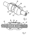
- eine Anschlussvorrichtung für eine Schlauchleitung an einem Arbeitsgerät im Schnitt,
- Fig. 10
- den Gegenstand der
Figur 9 in einer anderen Ausführungsform, - Fig. 11
- ein anderes Ausführungsbeispiel der Anschlussvorrichtung gemäß
Figur 9 , - Fig. 12
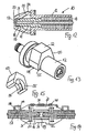
- eine Schlaucharmatur mit einer auf deren offenes Ende aufgesteckten Schutzkappe im Schnitt,
- Fig. 13
- den
Gegenstand der Figur 12 mit auf den Hülsenbereich der Schlaucharmatur aufgesteckter Schutzkappe, - Fig. 14
- den Gegenstand der
Figur 12 in einer anderen Ausführungsform mit einer axial auf dem Hülsenabschnitt der Schlaucharmatur fixierten Schutzkappe, - Fig. 15
- die
Schutzkappe gemäß Figur 14 in einer perspektivischen Einzeldarstellung, - Fig. 16
- den Gegenstand der
Figur 14 in einer Perspektivansicht, - Fig. 17
- die Anschluss- und Verbindungsvorrichtung gemäß
Figur 14 unter Einbeziehung eines äußeren Schutzschlauches, - Fig. 18
- den Gegenstand der
Figur 17 in einer Perspektivansicht.
- Fig. 1
- a connection for two hose line ends in section before pressure in the release position of the connection and connection device,
- Fig. 2
- the object of
FIG. 1 in the locking position of the connection and connection device under pressure,
- Fig. 3
- detail III
FIG. 2 . - Fig. 4
- the connection and connection device according to
FIG. 1 in a view with half-shells in their closed position, - Fig. 5
- the object of
FIG. 4 in another embodiment, - Fig. 6
- the object of
FIG. 4 or 5 in a further embodiment, - Fig. 7
- the object of
FIG. 6 on average, - Fig. 8
- a further embodiment of the compound of the two half-shells according to
FIGS. 4 to 7 . - Fig. 9
- a connection device for a hose line on a working device in section,
- Fig. 10
- the object of
FIG. 9 in another embodiment, - Fig. 11
- another embodiment of the connecting device according to
FIG. 9 . - Fig. 12
- a hose fitting with a plugged onto the open end cap in section,
- Fig. 13
- the object of
FIG. 12 with protective cap attached to the sleeve area of the hose fitting, - Fig. 14
- the object of
FIG. 12 in another embodiment with an axially fixed on the sleeve portion of the hose fitting cap, - Fig. 15
- the protective cap according to
FIG. 14 in a perspective individual representation, - Fig. 16
- the object of
FIG. 14 in a perspective view, - Fig. 17
- the connection and connection device according to
FIG. 14 including an outer protective tube, - Fig. 18
- the object of
FIG. 17 in a perspective view.
Wie sich zunächst aus
In dem über den Ringraum 13 zur Aufnahme des Schlauchkörpers vorstehenden Bereich ist die Hülse 12 mit einem in eine am Nippel 11 ausgebildete Nut 16 einpressbaren Vorsprung 15 versehen, so dass auch hierdurch die feste Verbindung zwischen dem Nippel 11 und der Hülse 12 unterstützt wird. An seinem äußersten vorderen Ende weist der Nippel 11 eine weitere Nut 17 zur Aufnahme eines darin eingelegten Dichtungsringes 18 auf. Mit diesem vorderen Ende und dem darauf sitzenden Dichtungsring 18 sind die beiden Nippel 11 der beiden zu verbindenden Schlaucharmaturen 10 von beiden Seiten her in eine zentral angeordnete Aufnahmebuchse 19 eingeschoben, bis die beiden Nippel 11 stirnseitig aneinander stoßen.In the over the
An ihrem stirnseitigen Ende weisen die beiden Hülsen 12 jeweils als einstückigen Bestandteil einen radial davon abstehenden Flanschring 20 auf, der an seinem äußeren Umfang einen in Richtung der Schlaucharmatur 10 ausgerichteten Vorsprung 21 hat.At its front end, the two
Die beiden Flanschringe 20 nebst dazwischen liegender Aufnahmebuchse 19 sind von zwei außen aufgesetzten Halbschalen 22 umschlossen, wobei sich die Halbschalen 22 noch über einen Teilbereich der jeweiligen Hülse 12 der Schlaucharmatur 10 erstrecken. In ihrem Inneren bilden die beiden zusammengesetzten Halbschalen 22 eine Aufnahmeausnehmung 23 aus, die zur passenden Aufnahme des Flanschringes 20 mit Vorsprung 21 der Schlaucharmatur 10 eingerichtet ist. Die Aufnahmeausnehmung 23 hat dabei eine solche axiale Erstreckung, dass die beiden Flanschringe 20 darin um ein gewisses Maß axial verschiebbar sind, wie noch erläutert wird. An ihrer dem Vorsprung 21 des Flanschringes 20 zugewandten Stirnseite 24 weisen die beiden Halbschalen 22 jeweils eine Nut 25 zur Aufnahme des Vorsprunges 21 auf.The two flange rings 20 together with an
Die
Obwohl es ausreichend ist, wenn die beiden Halbschalen 22 allein durch den Anpressdruck in Position gehalten sind, kann es zweckmäßig sein, für eine zusätzliche Festlegung der Halbschalen 22 aneinander zu sorgen.Although it is sufficient if the two half-
Hierzu zeigt
Eine alternative Möglichkeit ist in
Eine wiederum andere Ausführungsform ist in
Wie sich aus den
Das in
Bei dem in
Es ist üblich, derartige Schlaucharmaturen 10 an ihrem freien Ende vor der Montage durch Aufsetzen einer Schutzkappe zu schützen, und insoweit umfasst die erfindungsgemäße Anschluss- und Verbindungsvorrichtung gemäß
Der Schutzkappe 50 kann gemäß dem in den
Soweit insbesondere bei der Verwendung der Anschluss- und Verbindungsvorrichtung im Zusammenhang mit Hochdruckschläuchen in an sich bekannter Weise ein äußerer Schutzschlauch über den jeweiligen Hochdruckschlauch zu ziehen und an der Schlaucharmatur beziehungsweise der Anschluss- und Verbindungsvorrichtung festzulegen ist, gibt die erfindungsgemäße Anschluss- und Verbindungsvorrichtung die Möglichkeit, für eine entsprechend einfache Halterung eines Schutzschlauches 60 an der Anschluss- und Verbindungsvorrichtung zu sorgen. Aufgrund der Festlegung der miteinander zu verbindenden Schlaucharmaturen 10 durch die Halbschalen 22 reicht es aus, wenn der jeweilige Schutzschlauch 60 über die Hülse 12 jeder Schlaucharmatur 10 geschoben ist, so dass diese Hülse 12 beziehungsweise die Schlaucharmatur 10 wie ein Nippel einer Schlauchverbindung wirken. Der außen auf die Hülse 12 aufgeschobene Schutzschlauch 60 wird auf der Hülse 12 mittels einer äußeren Presshülse 61 festgelegt, die in an sich bekannter Weise mit einem stirnseitigen Vorsprung 62 in eine in der Hülse 12 ausgebildete Nut 63 eingreift und dadurch axial unverschieblich festgelegt ist. Mittels einer innenseitig ausgebildeten Verzahnung 64 hält die Presshülse 61 den Schutzschlauch 60 fest. Auch bei einer solchen Ausgestaltung kann die axiale Fixierung der einzusetzenden Schutzkappen 50 für eine zusätzliche Sicherung der Anschluss- und Verbindungsvorrichtung gegen ein Lösen genutzt werden, und hierzu sind die Lage der auf der Hülse 12 angebrachten Presshülse 61 und die Breite der Schutzkappe 50 derart aufeinander abgestimmt, dass durch die zwischen die Halbschalen 22 und die Presshülse 61 eingesetzte Schutzkappe 50 ein axiales Verschieben der Schlaucharmatur 10 in die Halbschalen 22 hinein ausgeschlossen ist.As far as in particular when using the connection and connection device in connection with high-pressure hoses in a conventional manner to pull an outer protective hose over the respective high-pressure hose and is set on the hose fitting or the connection and connection device, the connection and connection device according to the invention gives the opportunity to provide for a correspondingly simple mounting of a
Claims (22)
- A joining and connecting device for high-pressure lines for joining a hose line to a further hose line or to a high-pressure working implement, wherein the end of the hose line is provided with a hose fitting (10) that consists of a nipple (11) that can be slid into the inner core of a hose body, and of a sleeve (12) that is fitted onto the outer side of the hose body and can be connected to the nipple and pressed onto the hose body, wherein the hose fitting (10) connected to the hose body has a radially protruding flange ring (20), and that end of the nipple (11) that protrudes out of the hose body has a seal (18) that is fitted on the outer circumference thereof and can be inserted together with the seal (18) into a receiving bush (19), and the receiving bush (19) and the radially protruding flange ring (20) are surrounded by two half shells (22) that surround the receiving bush (19) and the flange ring (20) on the outside as a joining and connecting device, and wherein a recess (23) in the half shells (22), which recess serves for receiving the flange ring (20), is dimensioned such that an axial movement of the hose end with the hose fitting (10) attached thereto is enabled between a release position and a locking position for the half shells (22), said locking position being formed by the form-fitting engagement of the flange ring (20) with a receiving configuration (25) formed on the front sides of the half shells (22), characterized in that the two half shells (22), in addition to the receiving bush (19) and the flange ring (20), surround the outside of a section of the outer sleeve (12), which section adjoins the flange ring (20).
- The joining and connecting device according to claim 1, characterized in that the flange ring (20) engages with a protrusion (21) protruding axially in the direction of the hose body into a groove (25) formed as a receiving configuration in the front sides of the half shells (22).
- The joining and connecting device according to claim 1, characterized in that the flange ring (20) is attached on the front-side end of the sleeve (12).
- The joining and connecting device according to claim 3, characterized in that the flange ring (20) is an integral part of the sleeve (12).
- The joining and connecting device according to claim 1 or claim 2, characterized in that the flange ring (20) is attached to a region of the nipple (11), which region protrudes out of hose body, between the sleeve (12) and the receiving bush (19).
- The joining and connecting device according to any one of the claims 1 to 5, characterized in that the receiving bush (19) has such a length that the front end of the nipple (11), which front end has the seal (18), is positioned inside the receiving bush (19) in the release position as well as in the locking position.
- The joining and connecting device according to any one of the claims 1 to 6, characterized in that the two half shells (22) surrounding the receiving bush (19) and the flange ring (20) are held together in their closed position by means of a bent spring clip (31) fitted on the outer circumference of the half shells.
- The joining and connecting device according to any one of the claims 1 to 6, characterized in that the half shells (22) are held together in their closed position by means of U-shaped spring cotter pins (29) radially inserted through the outer ends of the half shells.
- The joining and connecting device according to any one of the claims 1 to 6, characterized in that the half shells (22) are held together in their closed position by means of an outer hinge (32).
- The joining and connecting device according to claim 9, characterized in that at the hinge axis (32) of the hinge, the half shells (22) are each held in spring leafs (33) which preload said half shells into their closed position and are connected to the half shells (22).
- The joining and connecting device according to claim 10, characterized in that the receiving bush (19) is surrounded by the half shells (22) in a form-locking manner and is fixed therein in an axially undisplaceable manner.
- The joining and connecting device according to any one of the claims 1 to 11 for connecting two hose lines, characterized in that the half shells (22) engage around the flange rings (20) of the two hose fittings (10) of the hose lines to be connected, including the receiving bush (19) arranged therebetween with the nipples (11) slid therein, and keep them together.
- The joining and connecting device according to any one of the claims 1 to 11 for connecting a hose line to a high-pressure working implement, characterized in that the receiving bush (19) is connected to the working implement, and the half shells (22), in their closed position, are fixed on the receiving bush (19) or on the working implement in an axially undisplaceable manner.
- The joining and connecting device according to any one of the claims 1 to 11, characterized in that the receiving bush (19) is formed as an adaptor (45) that can be connected to a working implement or to a hose line having a screw connection, and at the front-side end of the adaptor, the flange ring (20) is attached which, together with the flange ring (20) of the hose fitting (10), is surrounded by the half shells (22).
- The joining and connecting device according to claim 14, characterized in that an external thread is provided on the free end (47) of the adaptor (45).
- The joining and connecting device according to claim 14, characterized in that an internal thread is provided on the free end (47) of the adaptor (45).
- The joining and connecting device according to any one of the claims 1 to 16, characterized in that on the hose fitting (10), a removably held protective cap (50) for covering the open end of the hose fitting (10) is provided, and the hat-shaped protective cap (50) has a protective region (51) for axial and enclosing attaching onto the open end of the hose fitting (10), and further has a holding region (54) axially adjoining the protective region (51), which holding region has an outwardly curved wall region (55) for radially attaching the protective cap (50) onto the outer circumference of a section of the sleeve (12) of the hose fitting (10).
- The joining and connecting device according to claim 17, characterized in that the protective region (51) consists of a projection (53) for attaching onto the end of the hose fitting (10), which projection protrudes on the inside from the closed cover region (52).
- The joining and connecting device according to claim 17 or claim 18, characterized in that the outwardly curved wall regions (55) of the protective cap (50) are formed spring-elastically.
- The joining and connecting device according to any one of the claims 17 to claim 19, characterized in that the hat-shaped protective cap (50), in its position attached onto the hose fitting (10), is axially fixed by means of a protrusion (56) that is in each case arranged on the inner side of the wall regions (55) of the protective cap and engages into a groove (57) formed on the outer side of the sleeve (12), and the groove (57) is arranged on the sleeve (12) in such a manner that an axial displacement of the hose fitting (10) with the protective cap (50) attached thereon toward the half shells (22) is impossible.
- The joining and connecting device according to any one of the claims 17 to claim 20, characterized in that a protective hose (60) is provided which surrounds the outside of the high-pressure line with the hose fitting (10) connected thereto, which protective hose is slid with its associated end over that region of the sleeve (12) of the hose fitting (10) that protrudes from the half shells (22) and is fixed thereon by means of a pressing sleeve (61) fitted on the outside, and that the width of the protective cap (50) and the position of the pressing sleeve (61) fitted on the sleeve (12) are matched to one another in such a manner that the protective cap (50) can be inserted as a axial counter bearing between the half shells (22) and the pressing sleeve (61) in such a manner that an axial displacement of the hose fitting (10) toward the half shells (22) is impossible.
- The joining and connecting device according to claim 21, characterized in that the protective hose (60) consists of a flexible and stretchable material.
Applications Claiming Priority (2)
| Application Number | Priority Date | Filing Date | Title |
|---|---|---|---|
| DE202008006612U DE202008006612U1 (en) | 2008-05-15 | 2008-05-15 | Connection and connection device for high-pressure lines |
| PCT/EP2008/008953 WO2009138113A1 (en) | 2008-05-15 | 2008-10-23 | Joining and connecting device for high-pressure lines |
Publications (3)
| Publication Number | Publication Date |
|---|---|
| EP2276960A1 EP2276960A1 (en) | 2011-01-26 |
| EP2276960B1 true EP2276960B1 (en) | 2013-06-05 |
| EP2276960B8 EP2276960B8 (en) | 2013-07-10 |
Family
ID=39678433
Family Applications (1)
| Application Number | Title | Priority Date | Filing Date |
|---|---|---|---|
| EP08846210.6A Active EP2276960B8 (en) | 2008-05-15 | 2008-10-23 | Joining and connecting device for high-pressure lines |
Country Status (7)
| Country | Link |
|---|---|
| US (1) | US7938457B2 (en) |
| EP (1) | EP2276960B8 (en) |
| DE (1) | DE202008006612U1 (en) |
| DK (1) | DK2276960T3 (en) |
| ES (1) | ES2426221T3 (en) |
| PT (1) | PT2276960E (en) |
| WO (1) | WO2009138113A1 (en) |
Cited By (1)
| Publication number | Priority date | Publication date | Assignee | Title |
|---|---|---|---|---|
| WO2015028590A1 (en) | 2013-08-29 | 2015-03-05 | Christoph Nickel | Connecting element for joining hose and pipe sections |
Families Citing this family (10)
| Publication number | Priority date | Publication date | Assignee | Title |
|---|---|---|---|---|
| DE202009010333U1 (en) | 2009-06-10 | 2010-02-25 | Parker Hannifin Gmbh & Co. Kg | High-pressure hose arrangement with function monitoring |
| MD264Z (en) * | 2009-07-31 | 2011-03-31 | Ион РАССОХИН | Process for nipple connection to a hose |
| DE202011051325U1 (en) | 2011-09-16 | 2011-12-01 | Parker Hannifin Manufacturing Germany GmbH & Co. KG | Pressurized connection and connection device for high-pressure lines |
| US9518690B2 (en) * | 2014-09-23 | 2016-12-13 | Dominique Bélisle | Fire hose girdle |
| US10302241B2 (en) | 2014-10-30 | 2019-05-28 | Somero Enterprises, Inc. | Protective shield for concrete hose joints |
| CN105299357B (en) * | 2015-11-27 | 2017-12-22 | 江苏省绿岛管阀件有限公司 | A kind of adjustable pipeline connecting assemble |
| CN105299378B (en) * | 2015-11-27 | 2017-12-22 | 江苏省绿岛管阀件有限公司 | A kind of pipeline |
| CN106195473A (en) * | 2016-08-29 | 2016-12-07 | 南通爱慕希机械股份有限公司 | A kind of high-pressure pipe connector |
| CN110670286A (en) * | 2019-08-21 | 2020-01-10 | 海宁市创兴经编有限公司 | Connecting mechanism for shell in fabric heat setting finishing device |
| CN112696790B (en) * | 2020-12-23 | 2022-04-15 | 安徽郁金香新能源科技有限公司 | Integrated installation method for reducing water resistance of tail end system |
Family Cites Families (33)
| Publication number | Priority date | Publication date | Assignee | Title |
|---|---|---|---|---|
| US1043806A (en) * | 1909-05-18 | 1912-11-12 | American Bridge Company | Hose-coupling. |
| US1985012A (en) * | 1933-08-12 | 1934-12-18 | Lincoln Eng Co | Swivel |
| US2383010A (en) * | 1943-08-25 | 1945-08-21 | Albert W Miller | Detachable coupling |
| US2837351A (en) * | 1954-02-01 | 1958-06-03 | Cardox Corp | Electrically insulated pipe coupling with confined pressure-sealing means |
| US3041088A (en) * | 1959-06-18 | 1962-06-26 | Jr Ira M Brandon | Coupling assembly |
| US3195931A (en) * | 1963-03-18 | 1965-07-20 | Space Technology And Res Corp | Symmetrical hose coupling |
| DE2310680C2 (en) * | 1973-03-03 | 1975-04-10 | Karl 4040 Neuss Weinhold | Device for connecting two connectors for hose or pipe ends |
| GB1461606A (en) * | 1973-03-30 | 1977-01-13 | Jonsson N G | Couplings |
| US4236736A (en) * | 1978-05-01 | 1980-12-02 | Turnbuckle Products Corporation | Hose coupling |
| US4473369A (en) * | 1982-01-11 | 1984-09-25 | Baxter Travenol Laboratories, Inc. | Continuous ambulatory peritoneal dialysis clamping system |
| US4432759A (en) * | 1982-04-26 | 1984-02-21 | Abbott Laboratories | Connecting device for medical liquid containers |
| US4669760A (en) * | 1986-02-05 | 1987-06-02 | Flow Industries, Inc. | Swivel fitting arrangement for use in a pressurized fluid line |
| US4741559A (en) * | 1987-05-28 | 1988-05-03 | Berghman Earle E | Coupling protector |
| DE3921443A1 (en) * | 1989-06-30 | 1991-01-10 | Weinhold Karl | Hose holder with nozzle and connection - has at least two clamping jaws with inner peripheral groove into which fits ring with sleeve |
| US5269572A (en) * | 1992-08-28 | 1993-12-14 | Gold Star Manufacturing, Inc. | Apparatus and method for coupling elongated members |
| US5454603A (en) * | 1993-10-22 | 1995-10-03 | Staley, Jr.; Colin R. | Co-axial hose coupling adapted for replacing inner hose upon rupture thereof and method therefor |
| DE19513058C2 (en) * | 1995-04-07 | 1997-02-13 | Ford Werke Ag | Pipe connection |
| US5853200A (en) * | 1996-04-15 | 1998-12-29 | Gary A. Zieres | Hose coupling boot |
| DE19642338C1 (en) | 1996-10-14 | 1998-07-16 | Prange Karl Heinz | Connection element for connecting hose and pipe sections |
| US5895076A (en) * | 1996-11-04 | 1999-04-20 | Tyler J. Elliot | Hose coupling shroud |
| GB9801261D0 (en) * | 1998-01-21 | 1998-03-18 | Peters Joseph L | Couplings for medical cannulae |
| DE19939161C1 (en) * | 1999-08-20 | 2001-06-21 | Waluga Armaturen | Connection element for hoses and/or pipes has sleeve element with axial sloping surfaces, and clamp element acting with ring on hose/pipe nipple |
| DE19940147C2 (en) * | 1999-08-24 | 2001-08-16 | Karl Weinhold | Device for connecting two hose ends |
| GB0004212D0 (en) * | 2000-02-23 | 2000-04-12 | Plexus Ocean Syst Ltd | Pipe joint |
| US6565129B2 (en) * | 2001-06-21 | 2003-05-20 | Halliburton Energy Services, Inc. | Quick connect system and method for fluid devices |
| US6913294B2 (en) * | 2002-11-14 | 2005-07-05 | Halla Climate Control Canada, Inc. | Coupling for coaxial connection of fluid conduits |
| US20040227347A1 (en) * | 2003-05-12 | 2004-11-18 | Fundin Robert Lyle | Adaptable water diverting fixture |
| DE202004002063U1 (en) * | 2004-02-11 | 2004-04-22 | Prange, Karl-Heinz | Connecting element for connecting of two hose or pipe ends has sections of connecting nipples which are orientated in relation to one another in shoulder fashion inside connecting element having form widening pipe cross section |
| WO2006002459A1 (en) | 2004-07-02 | 2006-01-12 | Australasian Steel Products Pty Ltd | Hose assembly safety equipment |
| US7537245B2 (en) * | 2005-02-14 | 2009-05-26 | Medtronic, Inc. | Strain relief device and connector assemblies incorporating same |
| EP1726865B1 (en) * | 2005-05-27 | 2010-02-24 | NORMA Germany GmbH | Coupling assembly with end sections of two fluid conduits to be connected |
| DE202006007315U1 (en) | 2006-03-14 | 2006-07-20 | Falch Hochdruckstrahlsysteme Gmbh | Link fitting for high pressure hose has a non-rotating push-fit joining part |
| DE202006015598U1 (en) | 2006-10-11 | 2006-12-28 | Parker Hannifin Gmbh & Co. Kg | Hose connector comprises nipple which fits into hose and sleeve which fits over it, sleeve having section which grips groove on nipple and has flat surfaces for key which correspond with similar surfaces on groove |
-
2008
- 2008-05-15 DE DE202008006612U patent/DE202008006612U1/en not_active Expired - Lifetime
- 2008-10-23 DK DK08846210.6T patent/DK2276960T3/en active
- 2008-10-23 WO PCT/EP2008/008953 patent/WO2009138113A1/en active Application Filing
- 2008-10-23 ES ES08846210T patent/ES2426221T3/en active Active
- 2008-10-23 PT PT88462106T patent/PT2276960E/en unknown
- 2008-10-23 EP EP08846210.6A patent/EP2276960B8/en active Active
-
2009
- 2009-10-12 US US12/577,435 patent/US7938457B2/en active Active
Cited By (2)
| Publication number | Priority date | Publication date | Assignee | Title |
|---|---|---|---|---|
| WO2015028590A1 (en) | 2013-08-29 | 2015-03-05 | Christoph Nickel | Connecting element for joining hose and pipe sections |
| DE102013109403A1 (en) | 2013-08-29 | 2015-03-05 | Christoph Nickel | Connecting element for connecting hose and pipe sections |
Also Published As
| Publication number | Publication date |
|---|---|
| DE202008006612U1 (en) | 2008-08-07 |
| US20100059991A1 (en) | 2010-03-11 |
| EP2276960B8 (en) | 2013-07-10 |
| DK2276960T3 (en) | 2013-09-08 |
| WO2009138113A1 (en) | 2009-11-19 |
| US7938457B2 (en) | 2011-05-10 |
| PT2276960E (en) | 2013-09-05 |
| EP2276960A1 (en) | 2011-01-26 |
| ES2426221T3 (en) | 2013-10-22 |
Similar Documents
| Publication | Publication Date | Title |
|---|---|---|
| EP2276960B1 (en) | Joining and connecting device for high-pressure lines | |
| EP0728979A1 (en) | Sealing connection between a plastic pipe and a connecting piece made of metal | |
| EP3084153B1 (en) | Camshaft adjusting device, combustion engine and assembly method | |
| DE102011008084A1 (en) | High-pressure resistant connection device for pipes, has locking ring which is movable between assembly position and release position relative to rotation of union nut with respect to connecting portion | |
| EP2165104A1 (en) | Charge-air hose | |
| DE102014109418B4 (en) | Toilet seat joint and toilet seat set | |
| EP4127543A1 (en) | Plug-type coupling with pre-assembly locking | |
| DE202008005929U1 (en) | Connecting device for media lines in the region of a wall duct and wall element | |
| WO2006136151A1 (en) | Corrugated pipe | |
| EP2453157B1 (en) | Connection system for installation of a water-conveying device | |
| DE102008063582A1 (en) | Circular pipe clamp, has clamp ring with opening, pipe inserted into area of circumference of opening of ring, and clamping screw exhibiting thread-free shaft section covered over its entire length by flexible element | |
| DE102008061132B4 (en) | System of tapping fitting and borehole sealing sleeve | |
| EP1801485A1 (en) | Coupling device for interconnecting multiple fluid lines | |
| DE102004016051B4 (en) | Brake booster | |
| DE60305641T2 (en) | CONNECTING DEVICE FOR THE END-TO-END CONNECTION OF TWO TUBES | |
| EP3397889B1 (en) | Connection device | |
| EP3138703B1 (en) | Tyre pressure control system for a vehicle | |
| EP3542091A1 (en) | Coupling device for medium-conducting lines | |
| DE102012220516A1 (en) | Device for supporting mounting of clutch with releaser in clutch housing of gear box, has connection pipe that is inserted into opening of case which is displaceably mounted in fastening unit | |
| DE4223250A1 (en) | Automatically mountable plug-in coupling for hose lines in motor vehicles | |
| DE102013109403A1 (en) | Connecting element for connecting hose and pipe sections | |
| DE202011051325U1 (en) | Pressurized connection and connection device for high-pressure lines | |
| DE102010053129B4 (en) | High pressure resistant pipe connection with a compressible retaining ring | |
| DE202012003242U1 (en) | Fire protection device at transition to plastic pipe | |
| WO2009030250A1 (en) | Pipe coupling |
Legal Events
| Date | Code | Title | Description |
|---|---|---|---|
| PUAI | Public reference made under article 153(3) epc to a published international application that has entered the european phase |
Free format text: ORIGINAL CODE: 0009012 |
|
| 17P | Request for examination filed |
Effective date: 20090429 |
|
| AK | Designated contracting states |
Kind code of ref document: A1 Designated state(s): AT BE BG CH CY CZ DE DK EE ES FI FR GB GR HR HU IE IS IT LI LT LU LV MC MT NL NO PL PT RO SE SI SK TR |
|
| AX | Request for extension of the european patent |
Extension state: AL BA MK RS |
|
| RIN1 | Information on inventor provided before grant (corrected) |
Inventor name: LEVIN, MAXIM Inventor name: WEINHANDL, FRANZ |
|
| DAX | Request for extension of the european patent (deleted) | ||
| GRAP | Despatch of communication of intention to grant a patent |
Free format text: ORIGINAL CODE: EPIDOSNIGR1 |
|
| GRAS | Grant fee paid |
Free format text: ORIGINAL CODE: EPIDOSNIGR3 |
|
| GRAA | (expected) grant |
Free format text: ORIGINAL CODE: 0009210 |
|
| AK | Designated contracting states |
Kind code of ref document: B1 Designated state(s): AT BE BG CH CY CZ DE DK EE ES FI FR GB GR HR HU IE IS IT LI LT LU LV MC MT NL NO PL PT RO SE SI SK TR |
|
| REG | Reference to a national code |
Ref country code: GB Ref legal event code: FG4D Free format text: NOT ENGLISH |
|
| REG | Reference to a national code |
Ref country code: CH Ref legal event code: EP |
|
| REG | Reference to a national code |
Ref country code: AT Ref legal event code: REF Ref document number: 615871 Country of ref document: AT Kind code of ref document: T Effective date: 20130615 |
|
| RAP2 | Party data changed (patent owner data changed or rights of a patent transferred) |
Owner name: PARKER HANNIFIN MANUFACTURING GERMANY GMBH & CO. K |
|
| REG | Reference to a national code |
Ref country code: IE Ref legal event code: FG4D Free format text: LANGUAGE OF EP DOCUMENT: GERMAN |
|
| REG | Reference to a national code |
Ref country code: DE Ref legal event code: R096 Ref document number: 502008010085 Country of ref document: DE Effective date: 20130801 |
|
| REG | Reference to a national code |
Ref country code: AT Ref legal event code: HC Ref document number: 615871 Country of ref document: AT Kind code of ref document: T Owner name: PARKER HANNIFIN MANUFACTURING GERMANY GMBH & C, DE Effective date: 20130709 |
|
| REG | Reference to a national code |
Ref country code: PT Ref legal event code: SC4A Free format text: AVAILABILITY OF NATIONAL TRANSLATION Effective date: 20130829 |
|
| REG | Reference to a national code |
Ref country code: DK Ref legal event code: T3 |
|
| REG | Reference to a national code |
Ref country code: NL Ref legal event code: T3 |
|
| REG | Reference to a national code |
Ref country code: ES Ref legal event code: FG2A Ref document number: 2426221 Country of ref document: ES Kind code of ref document: T3 Effective date: 20131022 |
|
| PG25 | Lapsed in a contracting state [announced via postgrant information from national office to epo] |
Ref country code: SE Free format text: LAPSE BECAUSE OF FAILURE TO SUBMIT A TRANSLATION OF THE DESCRIPTION OR TO PAY THE FEE WITHIN THE PRESCRIBED TIME-LIMIT Effective date: 20130605 Ref country code: SI Free format text: LAPSE BECAUSE OF FAILURE TO SUBMIT A TRANSLATION OF THE DESCRIPTION OR TO PAY THE FEE WITHIN THE PRESCRIBED TIME-LIMIT Effective date: 20130605 Ref country code: NO Free format text: LAPSE BECAUSE OF FAILURE TO SUBMIT A TRANSLATION OF THE DESCRIPTION OR TO PAY THE FEE WITHIN THE PRESCRIBED TIME-LIMIT Effective date: 20130905 Ref country code: LT Free format text: LAPSE BECAUSE OF FAILURE TO SUBMIT A TRANSLATION OF THE DESCRIPTION OR TO PAY THE FEE WITHIN THE PRESCRIBED TIME-LIMIT Effective date: 20130605 Ref country code: FI Free format text: LAPSE BECAUSE OF FAILURE TO SUBMIT A TRANSLATION OF THE DESCRIPTION OR TO PAY THE FEE WITHIN THE PRESCRIBED TIME-LIMIT Effective date: 20130605 Ref country code: GR Free format text: LAPSE BECAUSE OF FAILURE TO SUBMIT A TRANSLATION OF THE DESCRIPTION OR TO PAY THE FEE WITHIN THE PRESCRIBED TIME-LIMIT Effective date: 20130906 |
|
| REG | Reference to a national code |
Ref country code: LT Ref legal event code: MG4D |
|
| PG25 | Lapsed in a contracting state [announced via postgrant information from national office to epo] |
Ref country code: BG Free format text: LAPSE BECAUSE OF FAILURE TO SUBMIT A TRANSLATION OF THE DESCRIPTION OR TO PAY THE FEE WITHIN THE PRESCRIBED TIME-LIMIT Effective date: 20130905 Ref country code: HR Free format text: LAPSE BECAUSE OF FAILURE TO SUBMIT A TRANSLATION OF THE DESCRIPTION OR TO PAY THE FEE WITHIN THE PRESCRIBED TIME-LIMIT Effective date: 20130605 Ref country code: PL Free format text: LAPSE BECAUSE OF FAILURE TO SUBMIT A TRANSLATION OF THE DESCRIPTION OR TO PAY THE FEE WITHIN THE PRESCRIBED TIME-LIMIT Effective date: 20130605 |
|
| PG25 | Lapsed in a contracting state [announced via postgrant information from national office to epo] |
Ref country code: LV Free format text: LAPSE BECAUSE OF FAILURE TO SUBMIT A TRANSLATION OF THE DESCRIPTION OR TO PAY THE FEE WITHIN THE PRESCRIBED TIME-LIMIT Effective date: 20130605 |
|
| PG25 | Lapsed in a contracting state [announced via postgrant information from national office to epo] |
Ref country code: IS Free format text: LAPSE BECAUSE OF FAILURE TO SUBMIT A TRANSLATION OF THE DESCRIPTION OR TO PAY THE FEE WITHIN THE PRESCRIBED TIME-LIMIT Effective date: 20131005 Ref country code: EE Free format text: LAPSE BECAUSE OF FAILURE TO SUBMIT A TRANSLATION OF THE DESCRIPTION OR TO PAY THE FEE WITHIN THE PRESCRIBED TIME-LIMIT Effective date: 20130605 Ref country code: SK Free format text: LAPSE BECAUSE OF FAILURE TO SUBMIT A TRANSLATION OF THE DESCRIPTION OR TO PAY THE FEE WITHIN THE PRESCRIBED TIME-LIMIT Effective date: 20130605 Ref country code: CZ Free format text: LAPSE BECAUSE OF FAILURE TO SUBMIT A TRANSLATION OF THE DESCRIPTION OR TO PAY THE FEE WITHIN THE PRESCRIBED TIME-LIMIT Effective date: 20130605 |
|
| PG25 | Lapsed in a contracting state [announced via postgrant information from national office to epo] |
Ref country code: RO Free format text: LAPSE BECAUSE OF FAILURE TO SUBMIT A TRANSLATION OF THE DESCRIPTION OR TO PAY THE FEE WITHIN THE PRESCRIBED TIME-LIMIT Effective date: 20130605 |
|
| PLBE | No opposition filed within time limit |
Free format text: ORIGINAL CODE: 0009261 |
|
| STAA | Information on the status of an ep patent application or granted ep patent |
Free format text: STATUS: NO OPPOSITION FILED WITHIN TIME LIMIT |
|
| BERE | Be: lapsed |
Owner name: PARKER HANNIFIN MANUFACTURING GERMANY G.M.B.H. & C Effective date: 20131031 |
|
| 26N | No opposition filed |
Effective date: 20140306 |
|
| PG25 | Lapsed in a contracting state [announced via postgrant information from national office to epo] |
Ref country code: MC Free format text: LAPSE BECAUSE OF FAILURE TO SUBMIT A TRANSLATION OF THE DESCRIPTION OR TO PAY THE FEE WITHIN THE PRESCRIBED TIME-LIMIT Effective date: 20130605 |
|
| REG | Reference to a national code |
Ref country code: DE Ref legal event code: R097 Ref document number: 502008010085 Country of ref document: DE Effective date: 20140306 |
|
| PG25 | Lapsed in a contracting state [announced via postgrant information from national office to epo] |
Ref country code: BE Free format text: LAPSE BECAUSE OF NON-PAYMENT OF DUE FEES Effective date: 20131031 |
|
| PG25 | Lapsed in a contracting state [announced via postgrant information from national office to epo] |
Ref country code: CY Free format text: LAPSE BECAUSE OF FAILURE TO SUBMIT A TRANSLATION OF THE DESCRIPTION OR TO PAY THE FEE WITHIN THE PRESCRIBED TIME-LIMIT Effective date: 20130605 |
|
| PG25 | Lapsed in a contracting state [announced via postgrant information from national office to epo] |
Ref country code: HU Free format text: LAPSE BECAUSE OF FAILURE TO SUBMIT A TRANSLATION OF THE DESCRIPTION OR TO PAY THE FEE WITHIN THE PRESCRIBED TIME-LIMIT; INVALID AB INITIO Effective date: 20081023 |
|
| PG25 | Lapsed in a contracting state [announced via postgrant information from national office to epo] |
Ref country code: MT Free format text: LAPSE BECAUSE OF FAILURE TO SUBMIT A TRANSLATION OF THE DESCRIPTION OR TO PAY THE FEE WITHIN THE PRESCRIBED TIME-LIMIT Effective date: 20130605 |
|
| REG | Reference to a national code |
Ref country code: FR Ref legal event code: PLFP Year of fee payment: 8 |
|
| REG | Reference to a national code |
Ref country code: FR Ref legal event code: PLFP Year of fee payment: 9 |
|
| REG | Reference to a national code |
Ref country code: FR Ref legal event code: PLFP Year of fee payment: 10 |
|
| REG | Reference to a national code |
Ref country code: FR Ref legal event code: PLFP Year of fee payment: 11 |
|
| P01 | Opt-out of the competence of the unified patent court (upc) registered |
Effective date: 20230524 |
|
| PGFP | Annual fee paid to national office [announced via postgrant information from national office to epo] |
Ref country code: NL Payment date: 20231026 Year of fee payment: 16 |
|
| PGFP | Annual fee paid to national office [announced via postgrant information from national office to epo] |
Ref country code: LU Payment date: 20231027 Year of fee payment: 16 |
|
| PGFP | Annual fee paid to national office [announced via postgrant information from national office to epo] |
Ref country code: GB Payment date: 20231027 Year of fee payment: 16 |
|
| PGFP | Annual fee paid to national office [announced via postgrant information from national office to epo] |
Ref country code: ES Payment date: 20231102 Year of fee payment: 16 |
|
| PGFP | Annual fee paid to national office [announced via postgrant information from national office to epo] |
Ref country code: TR Payment date: 20231006 Year of fee payment: 16 Ref country code: PT Payment date: 20231003 Year of fee payment: 16 Ref country code: IT Payment date: 20231023 Year of fee payment: 16 Ref country code: IE Payment date: 20231027 Year of fee payment: 16 Ref country code: FR Payment date: 20231025 Year of fee payment: 16 Ref country code: DK Payment date: 20231027 Year of fee payment: 16 Ref country code: DE Payment date: 20231027 Year of fee payment: 16 Ref country code: CH Payment date: 20231102 Year of fee payment: 16 Ref country code: AT Payment date: 20231004 Year of fee payment: 16 |