EP2276166A1 - Contrôleur de moteur numérique compact à base de FPGA - Google Patents
Contrôleur de moteur numérique compact à base de FPGA Download PDFInfo
- Publication number
- EP2276166A1 EP2276166A1 EP10251247A EP10251247A EP2276166A1 EP 2276166 A1 EP2276166 A1 EP 2276166A1 EP 10251247 A EP10251247 A EP 10251247A EP 10251247 A EP10251247 A EP 10251247A EP 2276166 A1 EP2276166 A1 EP 2276166A1
- Authority
- EP
- European Patent Office
- Prior art keywords
- fpga
- compact
- motor controller
- based digital
- commutation
- Prior art date
- Legal status (The legal status is an assumption and is not a legal conclusion. Google has not performed a legal analysis and makes no representation as to the accuracy of the status listed.)
- Granted
Links
- 238000000034 method Methods 0.000 claims abstract description 17
- 230000001143 conditioned effect Effects 0.000 claims abstract description 16
- 230000006854 communication Effects 0.000 claims description 20
- 238000004891 communication Methods 0.000 claims description 20
- 238000005516 engineering process Methods 0.000 claims description 5
- 238000010586 diagram Methods 0.000 description 3
- 230000008569 process Effects 0.000 description 3
- 230000005855 radiation Effects 0.000 description 3
- 230000007175 bidirectional communication Effects 0.000 description 2
- 238000006243 chemical reaction Methods 0.000 description 2
- 230000004044 response Effects 0.000 description 2
- 230000005355 Hall effect Effects 0.000 description 1
- 230000004075 alteration Effects 0.000 description 1
- 230000008859 change Effects 0.000 description 1
- 238000003708 edge detection Methods 0.000 description 1
- 230000000694 effects Effects 0.000 description 1
- 230000007613 environmental effect Effects 0.000 description 1
- 238000001914 filtration Methods 0.000 description 1
- 230000007257 malfunction Effects 0.000 description 1
- 238000004519 manufacturing process Methods 0.000 description 1
- 239000002245 particle Substances 0.000 description 1
- 239000004065 semiconductor Substances 0.000 description 1
- 238000006467 substitution reaction Methods 0.000 description 1
Images

Classifications
-
- H—ELECTRICITY
- H02—GENERATION; CONVERSION OR DISTRIBUTION OF ELECTRIC POWER
- H02P—CONTROL OR REGULATION OF ELECTRIC MOTORS, ELECTRIC GENERATORS OR DYNAMO-ELECTRIC CONVERTERS; CONTROLLING TRANSFORMERS, REACTORS OR CHOKE COILS
- H02P6/00—Arrangements for controlling synchronous motors or other dynamo-electric motors using electronic commutation dependent on the rotor position; Electronic commutators therefor
- H02P6/14—Electronic commutators
- H02P6/16—Circuit arrangements for detecting position
- H02P6/17—Circuit arrangements for detecting position and for generating speed information
-
- H—ELECTRICITY
- H02—GENERATION; CONVERSION OR DISTRIBUTION OF ELECTRIC POWER
- H02P—CONTROL OR REGULATION OF ELECTRIC MOTORS, ELECTRIC GENERATORS OR DYNAMO-ELECTRIC CONVERTERS; CONTROLLING TRANSFORMERS, REACTORS OR CHOKE COILS
- H02P6/00—Arrangements for controlling synchronous motors or other dynamo-electric motors using electronic commutation dependent on the rotor position; Electronic commutators therefor
- H02P6/34—Modelling or simulation for control purposes
Definitions
- the subject matter disclosed herein generally relates to digital motor controllers, and more particularly to compact field programmable gate array (FPGA) based digital motor controllers.
- FPGA compact field programmable gate array
- a brushless direct current (DC) motor can use switches to electrically control commutation.
- One or more sensors can be used to determine position or speed information for feedback control of the brushless DC motor.
- commutation control may be non-linear with respect to rotational speed of the motor. Non-linear period information complicates control logic, which can result in demanding mathematical calculations and complex algorithms for accurate control.
- control logic typically requires a microprocessor and accompanying computer system control elements, such as nonvolatile memory, volatile memory, arbitration logic, operating system software, and application software in the motor control loop.
- the use of a microprocessor and computer system control elements may be unsuitable for certain environments that are geometrically constrained and/or subject to harsh environmental conditions, for instance, high radiation environments.
- a compact field programmable gate array (FPGA)-based digital motor controller includes a sensor interface configured to receive sensor data from one or more sensors and generate conditioned sensor data. The one or more sensors provide position information for a DC brushless motor.
- the compact FPGA-based digital motor controller also includes a commutation control configured to create switching commands to control commutation for the DC brushless motor. The commutation control generates commutation pulses from the conditioned sensor data of the sensor interface.
- the compact FPGA-based digital motor controller also includes a time inverter configured to receive the commutation pulses. The time inverter converts the commutation pulses into a rotational speed of the DC brushless motor to provide a linear feedback control parameter.
- a method for an FPGA-based digital motor controller includes receiving sensor data from one or more sensors indicating position information for a DC brushless motor.
- the method further includes generating conditioned sensor data at a sensor interface implemented in hardware circuitry of the compact FPGA-based digital motor controller.
- the method also includes generating commutation pulses from the conditioned sensor data at a commutation control implemented in hardware circuitry of the compact FPGA-based digital motor controller.
- the method additionally includes converting the commutation pulses into a rotational speed of the DC brushless motor at a time inverter implemented in hardware circuitry of the compact FPGA-based digital motor controller to provide a linear feedback control parameter.
- the method further includes creating switching commands at the commutation control, to control commutation for the DC brushless motor.
- a further aspect of the invention is design structure for a compact FPGA-based digital motor controller tangibly embodied in a machine-readable medium.
- the design structure includes a sensor interface configured to receive sensor data from one or more sensors and generate conditioned sensor data, where the one or more sensors provide position information for a DC brushless motor.
- the design structure further includes a commutation control configured to create switching commands to control commutation for the DC brushless motor, the commutation control generating commutation pulses from the conditioned sensor data of the sensor interface.
- the design structure additionally includes a time inverter configured to receive the commutation pulses from the commutation control and convert the commutation pulses into a rotational speed of the DC brushless motor to provide a linear feedback control parameter.
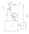
- FIG. 1 is a block diagram of an exemplary embodiment of a system with a compact FPGA-based digital motor controller
- FIG. 2 depicts a block diagram of a compact FPGA-based digital motor controller
- FIG. 3 depicts a process for providing a compact FPGA-based digital motor controller.
- FIG. 1 illustrates a block diagram of an exemplary embodiment of a system 100 with a compact field programmable gate array (FPGA)-based digital motor controller 102.
- the compact FPGA-based digital motor controller 102 receives input data from one or more sensors 104 via sensor data link 106.
- the one or more sensors 104 may be Hall effect sensors that detect magnetic field changes due to rotation of a direct current (DC) brushless motor 108.
- the one or more sensors 104 produce timing pulses responsive to a rotational position of the DC brushless motor 108.
- Motor drive transistors 110 switch a drive voltage source 112 onto motor drive link 114, providing switched current to establish commutation for the DC brushless motor 108.
- Switch commands are driven from the compact FPGA-based digital motor controller 102 to the motor drive transistors 110 using switch command link 116.
- Mechanical rotation of the DC brushless motor 108 can drive a rotary actuator 118 coupled through mechanical linkage 120.
- the mechanical linkage 120 may include gearing and other components (not depicted).
- the compact FPGA-based digital motor controller 102 may receive commands from a system controller 122 through a communication link 124.
- the system controller 122 can monitor the rotary actuator 118 using system sensors 126.
- An actuator feedback link 128 provides a feedback path between the rotary actuator 118 and the system sensors 126.
- a system sensor data link 130 can be used to pass data from the system sensors 126 to the system controller 122.
- the compact FPGA-based digital motor controller 102 performs closed-loop feedback control of the DC brushless motor 108, while the system controller 122 provides closed-loop feedback control of the rotary actuator 118.
- the system controller 122 provides control and configuration commands to the compact FPGA-based digital motor controller 102 and may also read status data from the compact FPGA-based digital motor controller 102.
- the system controller 122 can communicate with multiple instances of the compact FPGA-based digital motor controller 102 to command multiple instances of the DC brushless motor 108 and the rotary actuator 118 as part of a larger control system.
- FPGAs are semiconductor devices that can be configured after manufacturing according to hardware description language (HDL) files.
- HDL files may be implemented in a variety of formats, such as very high-speed integrated circuit hardware description language (VHDL) and/or Verilog files.
- VHDL very high-speed integrated circuit hardware description language
- Verilog files can refer to any programmable logic device capable of performing closed-loop digital motor control absent software execution.
- FIG. 2 depicts further details of an embodiment of the compact FPGA-based digital motor controller 102.
- the compact FPGA-based digital motor controller 102 includes hardware circuitry for a communication interface 202, data registers 204, sensor interface 206, time inverter 208, commutation control 210, and linear digital compensation filter 212.
- the communication interface 202, data registers 204, sensor interface 206, time inverter 208, commutation control 210, and linear digital compensation filter 212 can be implemented in a single compact FPGA device or distributed between multiple compact FPGA devices.
- the communication interface 202, data registers 204, sensor interface 206, time inverter 208, and commutation control 210 are grouped in a first compact FPGA 214, while the linear digital compensation filter 212 is included in a second compact FPGA 216.
- This configuration may enable a common implementation of the first compact FPGA 214 and customized implementations of multiple instances of the second compact FPGA 216 to support multiple configurations of the DC brushless motor 108 and the rotary actuator 118 of FIG. 1 as part of a larger control system.
- Both the first compact FPGA 214 and the second compact FPGA 216 can be implemented using antifuse (one-time programmable) technology to decrease susceptibility to radiation, such as alpha particles, which can cause circuits to malfunction.
- antifuse one-time programmable
- the physical area of the first compact FPGA 214 and the second compact FPGA 216 may be about 1 inch-square (2.54 centimeters-square), where the first compact FPGA 214 and the second compact FPGA 216 contain about 100,000 gates each. It will be understood that the physical dimensions and number of gates for the first compact FPGA 214 and the second compact FPGA 216 can vary within the scope of the invention.
- the communication interface 202 is coupled to the communication link 124 to provide bidirectional communication with the system controller 122 of FIG. 1 .
- the communication interface 202 may support a variety of communication protocols and standards known in the art, such as RS-485 to support point-to-point and multi-drop bus communication.
- Data path 218 provides a bidirectional communication link between the communication interface 202 and the data registers 204.
- the communication interface 202 can perform communication protocol conversion, enabling the system controller 122 of FIG. 1 to read and write values in the data registers 204.
- the data registers 204 may store a variety of configuration parameters, commands, and status information.
- the data registers 204 can interface with the time inverter 208 and linear digital compensation filter 212 via data path 220 and data path 222 respectively.
- the sensor interface 206 receives sensor data from the sensor data link 106 and can provide conditioned sensor data to the commutation control 210 using data path 224.
- the sensor data received at the sensor interface 206 from the one or more sensors 104 of FIG. 1 may be formatted as digital position data.
- each of the one or more sensors 104 can generate a pulse as a rotor of the DC brushless motor 108 of FIG. 1 rotates in close physical proximity to a given sensor of the one or more sensors 104.
- the sensor interface 206 can use edge detection logic to trigger one or more timers to start, stop, and/or capture time values as transitional edges are detected. Timers may be included in the sensor interface 206 and/or in the commutation control 210.
- the commutation control 210 can convert values received from the sensor interface 206 into commutation pulse data.
- the commutation pulse data may be formatted as time values indicating elapsed time between a common position and/or multiple positions relative to the DC brushless motor 108 of FIG. 1 .
- the commutation pulse data is sent to the time inverter 208 via data path 226.
- the time inverter 208 performs a mathematical inversion of time values from the commutation pulse data and outputs a rotational speed in revolutions-per-minute (RPM).
- the time inverter 208 is implemented exclusively in hardware circuitry and performs the mathematical inversion of time values (1/time) without software assistance to provide a linear feedback control parameter for controlling the DC brushless motor 108 of FIG. 1 .
- the time inverter 208 may include scalable parameters to control the accuracy of the calculations. In an exemplary embodiment, the accuracy of the time inverter 208 is scalable between 24 and 48 bits. The time inverter 208 may also support additional accuracy ranges. Converting non-linear commutation pulse data to RPM provides linearization to simplify closed loop control logic.
- Speed data passed to the data registers 204 can be read by the system controller 122 of FIG. 1 using the communication interface 202.
- Speed data passed to the linear digital compensation filter 212 supplies a linear feedback control parameter to determine an error value for controlling the DC brushless motor 108 of FIG. 1 .
- the linear digital compensation filter 212 provides compensation logic for stable control of the DC brushless motor 108 of FIG. 1 .
- the linear digital compensation filter 212 may include one or more digital filter stages, such as an infinite impulse response (IIR) filter or a finite impulse response (FIR) filter.
- the linear digital compensation filter 212 may also include control loop logic for implementing any combination of proportional, integral, and/or differential control.
- a commanded speed value can be received from the data registers 204, in addition to one or more gain values and filter coefficients.
- the values from the time inverter 208 provide control loop feedback for linear digital control. This avoids complexity that may be associated with more advanced control loop designs, such as non-linear state space control.
- the linear digital compensation filter 212 drives an output on data path 232 that attempts to reduce an error value between a commanded value and the actual value determined by the time inverter 208.
- the output on data path 232 is a compensation command for the commutation control 210, which may be in a pulse-width-modulation (PWM) command.
- PWM pulse-width-modulation
- the commutation control 210 converts compensation commands from the linear digital compensation filter 212 into switching commands to output on the switch command link 116.
- the commutation control 210 may issue commands as PWM cycles with an adjustable duty cycle and/or frequency.
- the commutation control 210 implements predictive control to avoid noise induced errors.
- the predictive control can include filtering self-generated noise.
- the commutation control 210 may use conditioned sensor data generated by the sensor interface 206 to determine when an error condition likely exists. For example, the commutation control 210 can determine that the rate of change between position data is too fast, indicating that false pulses may be present.
- the commutation control 210 can maintain a switching sequence from a previous switching cycle or issue no switching commands until the error condition is removed.
- data paths 220-232 may be combined into any combination of shared data path. Sharing data paths can reduce the amount of resources dedicated to routing data paths within the compact FPGA-based digital motor controller 102.
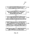
- FIG. 3 depicts a process 300 for providing a compact FPGA-based digital motor controller, such as the compact FPGA-based digital motor controller 102 of FIGs. 1 and 2 .
- the sensor interface 206 receives sensor data from one or more sensors 104 indicating position information for DC brushless motor 108.
- the sensor interface 206 generates conditioned sensor data.
- commutation control 210 generates commutation pulses from the conditioned sensor data.
- time inverter 208 converts the commutation pulses into a rotational speed of the DC brushless motor 108 to provide a linear feedback control parameter.
- commutation control 210 creates switching commands to control commutation for the DC brushless motor 108.
- Data registers 204 can be used to store command and status information, with communication interface 202 providing communication between the data registers 204 and system controller 122 of FIG. 1 .
- Linear digital compensation filter 212 may receive the rotational speed from the time inverter 208 and a speed command from the data registers 204, outputting a compensation command to the commutation control 210 responsive to the rotational speed and the speed command.
- the commutation control 210 can include additional functionality, such as performing predictive control to filter self-generated noise.
- embodiments of the invention may be embodied in the form of hardware or any processes and/or apparatuses for practicing the embodiments.
- the invention may also be embodied in the form of a design structure for the compact FPGA-based digital motor controller 102 of FIGs. 1 and 2 tangibly embodied in a machine-readable medium, such as a floppy diskette, CD ROM, DVD, flash drive, solid-state device, hard drive, or any other computer readable storage medium.
- One or more HDL files and/or supporting library files stored on one or more machine-readable mediums can provide the functional structure to program one or more FPGA devices to implement the compact FPGA-based digital motor controller 102.
- the design structure can be encoded in one or more FPGA devices, such as the first compact FPGA 214 and the second compact FPGA 216, by physically modifying the internal resistance of connections in each FPGA device to establish conductive paths for electrical current to flow.
- Performing a time inversion of position information for a DC brushless motor in hardware rather than software can avoid use of a microprocessor, computer system components, and software, resulting in a geometrically compact solution for DC brushless motor control.
- FPGA-based time inversion circuitry enables the use of a digital linear closed loop compensation filter instead of more complex non-linear controls. Converting time data into RPM for closed loop control may further simplify the control logic.
- the compact FPGA-based digital motor controller can also avoid the use of analog circuits to reduce board area and increase reliability. Implementing the compact FPGA-based digital motor controller in antifuse technology may further enhance reliability in high radiation environments, such as high altitude or space applications.
Landscapes
- Engineering & Computer Science (AREA)
- Power Engineering (AREA)
- Control Of Motors That Do Not Use Commutators (AREA)
Applications Claiming Priority (1)
| Application Number | Priority Date | Filing Date | Title |
|---|---|---|---|
| US12/501,660 US8294396B2 (en) | 2009-07-13 | 2009-07-13 | Compact FPGA-based digital motor controller |
Publications (2)
| Publication Number | Publication Date |
|---|---|
| EP2276166A1 true EP2276166A1 (fr) | 2011-01-19 |
| EP2276166B1 EP2276166B1 (fr) | 2018-04-18 |
Family
ID=42670417
Family Applications (1)
| Application Number | Title | Priority Date | Filing Date |
|---|---|---|---|
| EP10251247.2A Active EP2276166B1 (fr) | 2009-07-13 | 2010-07-13 | Contrôleur de moteur numérique compact à base de FPGA |
Country Status (3)
| Country | Link |
|---|---|
| US (2) | US8294396B2 (fr) |
| EP (1) | EP2276166B1 (fr) |
| JP (1) | JP2011024409A (fr) |
Cited By (6)
| Publication number | Priority date | Publication date | Assignee | Title |
|---|---|---|---|---|
| CN102355178A (zh) * | 2011-09-05 | 2012-02-15 | 武汉科技大学 | 一种基于fpga的同步电动机励磁系统 |
| JP2013110904A (ja) * | 2011-11-24 | 2013-06-06 | Fuji Electric Co Ltd | 電動機の駆動装置 |
| EP2770628A3 (fr) * | 2013-02-22 | 2015-03-04 | Hamilton Sundstrand Corporation | Contrôleur de moteur à courant continu sans balais à liaison variable pour des applications d'espace et durcies |
| EP2977727A1 (fr) * | 2014-07-22 | 2016-01-27 | Hamilton Sundstrand Space Systems International, Inc. | Détecteur de vitesse de moteur cc sans balais implemente dans un fpga |
| EP3193223A1 (fr) * | 2016-01-14 | 2017-07-19 | Hamilton Sundstrand Space Systems International, Inc. | Outil d'analyse de stabilité d'organe de commande de moteur numérique |
| US10008854B2 (en) | 2015-02-19 | 2018-06-26 | Enphase Energy, Inc. | Method and apparatus for time-domain droop control with integrated phasor current control |
Families Citing this family (26)
| Publication number | Priority date | Publication date | Assignee | Title |
|---|---|---|---|---|
| US8779705B2 (en) | 2011-02-25 | 2014-07-15 | Deere & Company | Synchronization of position and current measurements in an electric motor control application using an FPGA |
| US9980114B2 (en) | 2013-03-15 | 2018-05-22 | Elwha Llc | Systems and methods for communication management |
| US9832628B2 (en) | 2012-12-31 | 2017-11-28 | Elwha, Llc | Cost-effective mobile connectivity protocols |
| US9876762B2 (en) | 2012-12-31 | 2018-01-23 | Elwha Llc | Cost-effective mobile connectivity protocols |
| US9635605B2 (en) | 2013-03-15 | 2017-04-25 | Elwha Llc | Protocols for facilitating broader access in wireless communications |
| US9781664B2 (en) | 2012-12-31 | 2017-10-03 | Elwha Llc | Cost-effective mobile connectivity protocols |
| US9451394B2 (en) | 2012-12-31 | 2016-09-20 | Elwha Llc | Cost-effective mobile connectivity protocols |
| US9713013B2 (en) | 2013-03-15 | 2017-07-18 | Elwha Llc | Protocols for providing wireless communications connectivity maps |
| US8965288B2 (en) | 2012-12-31 | 2015-02-24 | Elwha Llc | Cost-effective mobile connectivity protocols |
| US9693214B2 (en) | 2013-03-15 | 2017-06-27 | Elwha Llc | Protocols for facilitating broader access in wireless communications |
| US9843917B2 (en) | 2013-03-15 | 2017-12-12 | Elwha, Llc | Protocols for facilitating charge-authorized connectivity in wireless communications |
| US9813887B2 (en) | 2013-03-15 | 2017-11-07 | Elwha Llc | Protocols for facilitating broader access in wireless communications responsive to charge authorization statuses |
| US9706382B2 (en) | 2013-03-15 | 2017-07-11 | Elwha Llc | Protocols for allocating communication services cost in wireless communications |
| US9807582B2 (en) | 2013-03-15 | 2017-10-31 | Elwha Llc | Protocols for facilitating broader access in wireless communications |
| US9706060B2 (en) | 2013-03-15 | 2017-07-11 | Elwha Llc | Protocols for facilitating broader access in wireless communications |
| US9781554B2 (en) | 2013-03-15 | 2017-10-03 | Elwha Llc | Protocols for facilitating third party authorization for a rooted communication device in wireless communications |
| US9596584B2 (en) | 2013-03-15 | 2017-03-14 | Elwha Llc | Protocols for facilitating broader access in wireless communications by conditionally authorizing a charge to an account of a third party |
| US9866706B2 (en) | 2013-03-15 | 2018-01-09 | Elwha Llc | Protocols for facilitating broader access in wireless communications |
| US9059732B2 (en) | 2013-03-21 | 2015-06-16 | Hamilton Sundstrand Corporation | Resolver-to-digital converter |
| JP2015171241A (ja) * | 2014-03-07 | 2015-09-28 | ハミルトン・サンドストランド・コーポレイションHamilton Sundstrand Corporation | モータ制御器システムおよびモータを制御するための方法 |
| CN104749997A (zh) * | 2015-03-16 | 2015-07-01 | 中国科学院光电研究院 | 用于激光跟踪仪精密伺服系统的驱动控制电路 |
| US9601003B2 (en) | 2015-08-17 | 2017-03-21 | Hamilton Sundstrand Space Systems International, Inc. | Sensor and control systems for electrical machines |
| CN105429524A (zh) * | 2015-12-15 | 2016-03-23 | 李哲 | 基于fpga的无刷直流电机调速系统 |
| US20180259091A1 (en) * | 2017-03-10 | 2018-09-13 | Hamilton Sundstrand Corporation | Control valve positioning system |
| US11199585B2 (en) | 2019-03-26 | 2021-12-14 | Hamilton Sundstrand Corporation | Highspeed data interface for distributed system motor controllers |
| EP4423903A1 (fr) * | 2021-10-28 | 2024-09-04 | Atieva, Inc. | Gestion de défaillance dans un groupe motopropulseur de véhicule électrique |
Citations (3)
| Publication number | Priority date | Publication date | Assignee | Title |
|---|---|---|---|---|
| EP0812057A1 (fr) * | 1995-03-14 | 1997-12-10 | A.O. Smith Corporation | Moteur à reluctance commuté muni d'une détection de la position du rotor |
| US6351048B1 (en) * | 1999-06-22 | 2002-02-26 | Levitronix Llc | Electrical rotary drive |
| WO2004004109A2 (fr) * | 2002-07-01 | 2004-01-08 | Xidem, Inc. | Moteur electrique a commande electronique |
Family Cites Families (32)
| Publication number | Priority date | Publication date | Assignee | Title |
|---|---|---|---|---|
| US4254369A (en) * | 1978-11-13 | 1981-03-03 | The Singer Company | High accuracy shaft angle linear DC voltage conversion using low accuracy devices |
| US4513378A (en) * | 1981-10-20 | 1985-04-23 | Antkowiak Edward T | High-accuracy navigating apparatus with step-driven projected chart |
| US4751438A (en) * | 1985-12-18 | 1988-06-14 | Sundstrand Corporation | Brushless DC motor control |
| JPS62277085A (ja) * | 1986-05-24 | 1987-12-01 | Ricoh Res Inst Of Gen Electron | 直流サ−ボモ−タ制御方式 |
| JPH0375567A (ja) | 1989-08-17 | 1991-03-29 | Toshiba Corp | 速度検出方式 |
| US5350988A (en) | 1990-07-10 | 1994-09-27 | Alliedsignal, Inc. | Digital motor controller |
| EP0515043A3 (en) | 1991-05-24 | 1993-11-18 | Actel Corp | Direct interconnect for functional circuit module array |
| AU4798793A (en) * | 1992-08-10 | 1994-03-03 | Monolithic System Technology, Inc. | Fault-tolerant, high-speed bus system and bus interface for wafer-scale integration |
| US5349248A (en) * | 1992-09-03 | 1994-09-20 | Xilinx, Inc. | Adaptive programming method for antifuse technology |
| US5426614A (en) * | 1994-01-13 | 1995-06-20 | Texas Instruments Incorporated | Memory cell with programmable antifuse technology |
| US5998783A (en) * | 1994-06-01 | 1999-12-07 | Stridsberg Innovation Ab | Heat protected position transducer in an electric motor |
| US5999168A (en) * | 1995-09-27 | 1999-12-07 | Immersion Corporation | Haptic accelerator for force feedback computer peripherals |
| EP1346461B1 (fr) * | 2000-12-30 | 2008-07-30 | Hamilton Sundstrand Corporation | Systeme de commande de commutation et de vitesse pour moteur sans balais a courant continu |
| US7055038B2 (en) * | 2001-05-07 | 2006-05-30 | Ati International Srl | Method and apparatus for maintaining secure and nonsecure data in a shared memory system |
| JP4552353B2 (ja) * | 2001-05-11 | 2010-09-29 | ソニー株式会社 | サーボ・アクチュエータ並びにその位置検出装置 |
| US6808345B2 (en) * | 2001-10-16 | 2004-10-26 | Toshiba Kikai Kabushiki Kaisha | Tool, tool holder, and machine tool |
| US7362070B2 (en) * | 2002-11-04 | 2008-04-22 | Hamilton Sundstrand Corporation | Electric motor control system including position determination and error correction |
| JP2004201487A (ja) * | 2002-11-28 | 2004-07-15 | Nsk Ltd | モータ及びその駆動制御装置 |
| JP2004242389A (ja) | 2003-02-04 | 2004-08-26 | Daiwa Industries Ltd | センサレスdcブラシレスモータ |
| US7245103B2 (en) * | 2003-03-03 | 2007-07-17 | Lexmark International, Inc. | Motor speed and position control |
| US7607437B2 (en) * | 2003-08-04 | 2009-10-27 | Cardinal Health 203, Inc. | Compressor control system and method for a portable ventilator |
| JP2005102377A (ja) | 2003-09-24 | 2005-04-14 | Gifu Univ | 多軸モータ制御システム |
| US7205738B2 (en) * | 2004-03-24 | 2007-04-17 | Lexmark International, Inc. | Method and apparatus for time-based dc motor commutation |
| US7332884B2 (en) * | 2004-07-16 | 2008-02-19 | Hamilton Sundstrand Corporation | Electric motor control strategies |
| JP3814826B2 (ja) * | 2004-12-10 | 2006-08-30 | 有限会社シー・アンド・エス国際研究所 | 同期電動機のベクトル制御方法 |
| US7245096B2 (en) * | 2005-11-21 | 2007-07-17 | Comair Rotron, Inc. | Method and apparatus for controlling the speed of a DC motor |
| US7466088B2 (en) * | 2005-12-16 | 2008-12-16 | Hamilton Sundstrand Corporation | Signal control for motor position determination |
| US7895560B2 (en) * | 2006-10-02 | 2011-02-22 | William Stuart Lovell | Continuous flow instant logic binary circuitry actively structured by code-generated pass transistor interconnects |
| US7489097B2 (en) * | 2006-11-02 | 2009-02-10 | Chrysler Llc | Sensorless position detection for a brushless direct current motor during inverter standby |
| CA2645781C (fr) * | 2006-12-22 | 2011-04-12 | Sidense Corp. | Registre de donnees double fonction |
| US7835630B2 (en) * | 2007-04-06 | 2010-11-16 | The Johns Hopkins University | Adaptive and reconfigurable system for DC motor control |
| US8290782B2 (en) * | 2008-07-24 | 2012-10-16 | Dts, Inc. | Compression of audio scale-factors by two-dimensional transformation |
-
2009
- 2009-07-13 US US12/501,660 patent/US8294396B2/en not_active Ceased
-
2010
- 2010-06-23 JP JP2010142133A patent/JP2011024409A/ja not_active Ceased
- 2010-07-13 EP EP10251247.2A patent/EP2276166B1/fr active Active
-
2013
- 2013-07-16 US US13/943,193 patent/USRE45388E1/en active Active
Patent Citations (3)
| Publication number | Priority date | Publication date | Assignee | Title |
|---|---|---|---|---|
| EP0812057A1 (fr) * | 1995-03-14 | 1997-12-10 | A.O. Smith Corporation | Moteur à reluctance commuté muni d'une détection de la position du rotor |
| US6351048B1 (en) * | 1999-06-22 | 2002-02-26 | Levitronix Llc | Electrical rotary drive |
| WO2004004109A2 (fr) * | 2002-07-01 | 2004-01-08 | Xidem, Inc. | Moteur electrique a commande electronique |
Non-Patent Citations (3)
| Title |
|---|
| "Miniature Motor Control Daughter Card for Actel IGLOO Icicle Kit", May 2008 (2008-05-01), XP002601681, Retrieved from the Internet <URL:http://www.actel.com/products/solutions/motorcontrol/minicard.aspx> [retrieved on 20100908] * |
| CRAIG HACKNEY: "FPGA Motor Control Reference Design", 16 September 2005 (2005-09-16), XP002600283, Retrieved from the Internet <URL:http://www.xilinx.com/support/documentation/application_notes/xapp808.pdf> [retrieved on 20100908] * |
| SHIVA@ISHNATEK.COM: "Implementing a Brushless DC Motor Controller on an IGLOO FPGA", 2008, XP002600282, Retrieved from the Internet <URL:http://www.eetasia.com/STATIC/PDF/200810/EEOL_2008OCT01_PL_AN_01.pdf?SOURCES=DOWNLOAD> [retrieved on 20100908] * |
Cited By (10)
| Publication number | Priority date | Publication date | Assignee | Title |
|---|---|---|---|---|
| CN102355178A (zh) * | 2011-09-05 | 2012-02-15 | 武汉科技大学 | 一种基于fpga的同步电动机励磁系统 |
| CN102355178B (zh) * | 2011-09-05 | 2013-08-21 | 武汉科技大学 | 一种基于fpga的同步电动机励磁系统 |
| JP2013110904A (ja) * | 2011-11-24 | 2013-06-06 | Fuji Electric Co Ltd | 電動機の駆動装置 |
| EP2770628A3 (fr) * | 2013-02-22 | 2015-03-04 | Hamilton Sundstrand Corporation | Contrôleur de moteur à courant continu sans balais à liaison variable pour des applications d'espace et durcies |
| EP2977727A1 (fr) * | 2014-07-22 | 2016-01-27 | Hamilton Sundstrand Space Systems International, Inc. | Détecteur de vitesse de moteur cc sans balais implemente dans un fpga |
| US9742326B2 (en) | 2014-07-22 | 2017-08-22 | Hamilton Sundstrand Space Systems International, Inc. | Field programmable gate array based brushless DC motor speed detector |
| US10008854B2 (en) | 2015-02-19 | 2018-06-26 | Enphase Energy, Inc. | Method and apparatus for time-domain droop control with integrated phasor current control |
| US10951037B2 (en) | 2015-02-19 | 2021-03-16 | Enphase Energy, Inc. | Method and apparatus for time-domain droop control with integrated phasor current control |
| US11355936B2 (en) | 2015-02-19 | 2022-06-07 | Enphase Energy, Inc. | Method and apparatus for time-domain droop control with integrated phasor current control |
| EP3193223A1 (fr) * | 2016-01-14 | 2017-07-19 | Hamilton Sundstrand Space Systems International, Inc. | Outil d'analyse de stabilité d'organe de commande de moteur numérique |
Also Published As
| Publication number | Publication date |
|---|---|
| USRE45388E1 (en) | 2015-02-24 |
| US8294396B2 (en) | 2012-10-23 |
| JP2011024409A (ja) | 2011-02-03 |
| EP2276166B1 (fr) | 2018-04-18 |
| US20110006713A1 (en) | 2011-01-13 |
Similar Documents
| Publication | Publication Date | Title |
|---|---|---|
| USRE45388E1 (en) | Compact FPGA-based digital motor controller | |
| JP5917294B2 (ja) | モータ駆動回路 | |
| JP5491207B2 (ja) | ステッピングモータの駆動装置 | |
| JPWO2009110206A1 (ja) | ブラシレスモータ装置及び制御装置 | |
| JP2010273502A (ja) | モータ駆動装置およびモータ駆動方法 | |
| EP3399640B1 (fr) | Dispositif de commande de moteur et procédé de commande de dispositif de commande de moteur | |
| US10284054B2 (en) | Motor control device | |
| CN104426437B (zh) | 电机控制装置 | |
| CN106655910A (zh) | 电机驱动设备和电机系统 | |
| JP2008079483A (ja) | モータ駆動回路、駆動装置、ならびに電子機器 | |
| JP5313454B2 (ja) | 電動車両の停止制御方法 | |
| JP5855686B2 (ja) | モータ駆動回路の逆起電力のゼロクロス点検出装置及び方法 | |
| CN101292417B (zh) | 电机驱动电路和使用了它的盘装置 | |
| JP2011064470A (ja) | エンコーダーシステム | |
| EP2977727B1 (fr) | Détecteur de vitesse de moteur cc sans balais implemente dans un fpga | |
| JP2005151792A (ja) | モータ制御回路 | |
| JP5493680B2 (ja) | モータ制御装置および電動パワーステアリング装置 | |
| CN101499756B (zh) | 控制一直流无刷马达的方法及控制电路 | |
| CN111344943B (zh) | 控制器、具有该控制器的马达控制系统以及具有该马达控制系统的电动助力转向系统 | |
| TWI531151B (zh) | 模組化風扇馬達控制電路及其控制方法 | |
| JP4447109B2 (ja) | ブラシレスモータ駆動回路 | |
| JP4451428B2 (ja) | 2相ステッピングモータの駆動回路 | |
| JP2021523665A (ja) | 外部部材の駆動または位置決め用メカトロニックアセンブリ | |
| JP2012023880A (ja) | ブラシレスモータの制御装置 | |
| JP6273457B2 (ja) | モータ制御装置 |
Legal Events
| Date | Code | Title | Description |
|---|---|---|---|
| PUAI | Public reference made under article 153(3) epc to a published international application that has entered the european phase |
Free format text: ORIGINAL CODE: 0009012 |
|
| AK | Designated contracting states |
Kind code of ref document: A1 Designated state(s): AL AT BE BG CH CY CZ DE DK EE ES FI FR GB GR HR HU IE IS IT LI LT LU LV MC MK MT NL NO PL PT RO SE SI SK SM TR |
|
| AX | Request for extension of the european patent |
Extension state: BA ME RS |
|
| 17P | Request for examination filed |
Effective date: 20110719 |
|
| RAP1 | Party data changed (applicant data changed or rights of an application transferred) |
Owner name: HAMILTON SUNDSTRAND SPACE SYSTEMS INTERNATIONAL, I |
|
| 17Q | First examination report despatched |
Effective date: 20150415 |
|
| REG | Reference to a national code |
Ref country code: DE Ref legal event code: R079 Ref document number: 602010049981 Country of ref document: DE Free format text: PREVIOUS MAIN CLASS: H02P0006000000 Ipc: H02P0006170000 |
|
| GRAP | Despatch of communication of intention to grant a patent |
Free format text: ORIGINAL CODE: EPIDOSNIGR1 |
|
| STAA | Information on the status of an ep patent application or granted ep patent |
Free format text: STATUS: GRANT OF PATENT IS INTENDED |
|
| RIC1 | Information provided on ipc code assigned before grant |
Ipc: H02P 6/17 20160101AFI20171009BHEP Ipc: H02P 6/34 20160101ALI20171009BHEP |
|
| INTG | Intention to grant announced |
Effective date: 20171031 |
|
| GRAS | Grant fee paid |
Free format text: ORIGINAL CODE: EPIDOSNIGR3 |
|
| GRAA | (expected) grant |
Free format text: ORIGINAL CODE: 0009210 |
|
| STAA | Information on the status of an ep patent application or granted ep patent |
Free format text: STATUS: THE PATENT HAS BEEN GRANTED |
|
| AK | Designated contracting states |
Kind code of ref document: B1 Designated state(s): AL AT BE BG CH CY CZ DE DK EE ES FI FR GB GR HR HU IE IS IT LI LT LU LV MC MK MT NL NO PL PT RO SE SI SK SM TR |
|
| REG | Reference to a national code |
Ref country code: GB Ref legal event code: FG4D |
|
| REG | Reference to a national code |
Ref country code: CH Ref legal event code: EP |
|
| REG | Reference to a national code |
Ref country code: AT Ref legal event code: REF Ref document number: 991483 Country of ref document: AT Kind code of ref document: T Effective date: 20180515 |
|
| REG | Reference to a national code |
Ref country code: IE Ref legal event code: FG4D |
|
| REG | Reference to a national code |
Ref country code: DE Ref legal event code: R096 Ref document number: 602010049981 Country of ref document: DE |
|
| REG | Reference to a national code |
Ref country code: FR Ref legal event code: PLFP Year of fee payment: 9 |
|
| REG | Reference to a national code |
Ref country code: NL Ref legal event code: MP Effective date: 20180418 |
|
| REG | Reference to a national code |
Ref country code: LT Ref legal event code: MG4D |
|
| PG25 | Lapsed in a contracting state [announced via postgrant information from national office to epo] |
Ref country code: NL Free format text: LAPSE BECAUSE OF FAILURE TO SUBMIT A TRANSLATION OF THE DESCRIPTION OR TO PAY THE FEE WITHIN THE PRESCRIBED TIME-LIMIT Effective date: 20180418 |
|
| PG25 | Lapsed in a contracting state [announced via postgrant information from national office to epo] |
Ref country code: ES Free format text: LAPSE BECAUSE OF FAILURE TO SUBMIT A TRANSLATION OF THE DESCRIPTION OR TO PAY THE FEE WITHIN THE PRESCRIBED TIME-LIMIT Effective date: 20180418 Ref country code: AL Free format text: LAPSE BECAUSE OF FAILURE TO SUBMIT A TRANSLATION OF THE DESCRIPTION OR TO PAY THE FEE WITHIN THE PRESCRIBED TIME-LIMIT Effective date: 20180418 Ref country code: PL Free format text: LAPSE BECAUSE OF FAILURE TO SUBMIT A TRANSLATION OF THE DESCRIPTION OR TO PAY THE FEE WITHIN THE PRESCRIBED TIME-LIMIT Effective date: 20180418 Ref country code: SE Free format text: LAPSE BECAUSE OF FAILURE TO SUBMIT A TRANSLATION OF THE DESCRIPTION OR TO PAY THE FEE WITHIN THE PRESCRIBED TIME-LIMIT Effective date: 20180418 Ref country code: NO Free format text: LAPSE BECAUSE OF FAILURE TO SUBMIT A TRANSLATION OF THE DESCRIPTION OR TO PAY THE FEE WITHIN THE PRESCRIBED TIME-LIMIT Effective date: 20180718 Ref country code: FI Free format text: LAPSE BECAUSE OF FAILURE TO SUBMIT A TRANSLATION OF THE DESCRIPTION OR TO PAY THE FEE WITHIN THE PRESCRIBED TIME-LIMIT Effective date: 20180418 Ref country code: LT Free format text: LAPSE BECAUSE OF FAILURE TO SUBMIT A TRANSLATION OF THE DESCRIPTION OR TO PAY THE FEE WITHIN THE PRESCRIBED TIME-LIMIT Effective date: 20180418 Ref country code: BG Free format text: LAPSE BECAUSE OF FAILURE TO SUBMIT A TRANSLATION OF THE DESCRIPTION OR TO PAY THE FEE WITHIN THE PRESCRIBED TIME-LIMIT Effective date: 20180718 |
|
| PG25 | Lapsed in a contracting state [announced via postgrant information from national office to epo] |
Ref country code: HR Free format text: LAPSE BECAUSE OF FAILURE TO SUBMIT A TRANSLATION OF THE DESCRIPTION OR TO PAY THE FEE WITHIN THE PRESCRIBED TIME-LIMIT Effective date: 20180418 Ref country code: GR Free format text: LAPSE BECAUSE OF FAILURE TO SUBMIT A TRANSLATION OF THE DESCRIPTION OR TO PAY THE FEE WITHIN THE PRESCRIBED TIME-LIMIT Effective date: 20180719 Ref country code: LV Free format text: LAPSE BECAUSE OF FAILURE TO SUBMIT A TRANSLATION OF THE DESCRIPTION OR TO PAY THE FEE WITHIN THE PRESCRIBED TIME-LIMIT Effective date: 20180418 |
|
| REG | Reference to a national code |
Ref country code: AT Ref legal event code: MK05 Ref document number: 991483 Country of ref document: AT Kind code of ref document: T Effective date: 20180418 |
|
| PG25 | Lapsed in a contracting state [announced via postgrant information from national office to epo] |
Ref country code: PT Free format text: LAPSE BECAUSE OF FAILURE TO SUBMIT A TRANSLATION OF THE DESCRIPTION OR TO PAY THE FEE WITHIN THE PRESCRIBED TIME-LIMIT Effective date: 20180820 |
|
| REG | Reference to a national code |
Ref country code: DE Ref legal event code: R097 Ref document number: 602010049981 Country of ref document: DE |
|
| PG25 | Lapsed in a contracting state [announced via postgrant information from national office to epo] |
Ref country code: CZ Free format text: LAPSE BECAUSE OF FAILURE TO SUBMIT A TRANSLATION OF THE DESCRIPTION OR TO PAY THE FEE WITHIN THE PRESCRIBED TIME-LIMIT Effective date: 20180418 Ref country code: SK Free format text: LAPSE BECAUSE OF FAILURE TO SUBMIT A TRANSLATION OF THE DESCRIPTION OR TO PAY THE FEE WITHIN THE PRESCRIBED TIME-LIMIT Effective date: 20180418 Ref country code: RO Free format text: LAPSE BECAUSE OF FAILURE TO SUBMIT A TRANSLATION OF THE DESCRIPTION OR TO PAY THE FEE WITHIN THE PRESCRIBED TIME-LIMIT Effective date: 20180418 Ref country code: AT Free format text: LAPSE BECAUSE OF FAILURE TO SUBMIT A TRANSLATION OF THE DESCRIPTION OR TO PAY THE FEE WITHIN THE PRESCRIBED TIME-LIMIT Effective date: 20180418 Ref country code: DK Free format text: LAPSE BECAUSE OF FAILURE TO SUBMIT A TRANSLATION OF THE DESCRIPTION OR TO PAY THE FEE WITHIN THE PRESCRIBED TIME-LIMIT Effective date: 20180418 Ref country code: EE Free format text: LAPSE BECAUSE OF FAILURE TO SUBMIT A TRANSLATION OF THE DESCRIPTION OR TO PAY THE FEE WITHIN THE PRESCRIBED TIME-LIMIT Effective date: 20180418 |
|
| PLBE | No opposition filed within time limit |
Free format text: ORIGINAL CODE: 0009261 |
|
| STAA | Information on the status of an ep patent application or granted ep patent |
Free format text: STATUS: NO OPPOSITION FILED WITHIN TIME LIMIT |
|
| PG25 | Lapsed in a contracting state [announced via postgrant information from national office to epo] |
Ref country code: IT Free format text: LAPSE BECAUSE OF FAILURE TO SUBMIT A TRANSLATION OF THE DESCRIPTION OR TO PAY THE FEE WITHIN THE PRESCRIBED TIME-LIMIT Effective date: 20180418 Ref country code: SM Free format text: LAPSE BECAUSE OF FAILURE TO SUBMIT A TRANSLATION OF THE DESCRIPTION OR TO PAY THE FEE WITHIN THE PRESCRIBED TIME-LIMIT Effective date: 20180418 |
|
| REG | Reference to a national code |
Ref country code: CH Ref legal event code: PL |
|
| 26N | No opposition filed |
Effective date: 20190121 |
|
| PG25 | Lapsed in a contracting state [announced via postgrant information from national office to epo] |
Ref country code: MC Free format text: LAPSE BECAUSE OF FAILURE TO SUBMIT A TRANSLATION OF THE DESCRIPTION OR TO PAY THE FEE WITHIN THE PRESCRIBED TIME-LIMIT Effective date: 20180418 Ref country code: LU Free format text: LAPSE BECAUSE OF NON-PAYMENT OF DUE FEES Effective date: 20180713 |
|
| REG | Reference to a national code |
Ref country code: BE Ref legal event code: MM Effective date: 20180731 |
|
| REG | Reference to a national code |
Ref country code: IE Ref legal event code: MM4A |
|
| PG25 | Lapsed in a contracting state [announced via postgrant information from national office to epo] |
Ref country code: LI Free format text: LAPSE BECAUSE OF NON-PAYMENT OF DUE FEES Effective date: 20180731 Ref country code: CH Free format text: LAPSE BECAUSE OF NON-PAYMENT OF DUE FEES Effective date: 20180731 Ref country code: IE Free format text: LAPSE BECAUSE OF NON-PAYMENT OF DUE FEES Effective date: 20180713 |
|
| PG25 | Lapsed in a contracting state [announced via postgrant information from national office to epo] |
Ref country code: BE Free format text: LAPSE BECAUSE OF NON-PAYMENT OF DUE FEES Effective date: 20180731 Ref country code: SI Free format text: LAPSE BECAUSE OF FAILURE TO SUBMIT A TRANSLATION OF THE DESCRIPTION OR TO PAY THE FEE WITHIN THE PRESCRIBED TIME-LIMIT Effective date: 20180418 |
|
| PG25 | Lapsed in a contracting state [announced via postgrant information from national office to epo] |
Ref country code: MT Free format text: LAPSE BECAUSE OF NON-PAYMENT OF DUE FEES Effective date: 20180713 |
|
| PG25 | Lapsed in a contracting state [announced via postgrant information from national office to epo] |
Ref country code: TR Free format text: LAPSE BECAUSE OF FAILURE TO SUBMIT A TRANSLATION OF THE DESCRIPTION OR TO PAY THE FEE WITHIN THE PRESCRIBED TIME-LIMIT Effective date: 20180418 |
|
| PG25 | Lapsed in a contracting state [announced via postgrant information from national office to epo] |
Ref country code: HU Free format text: LAPSE BECAUSE OF FAILURE TO SUBMIT A TRANSLATION OF THE DESCRIPTION OR TO PAY THE FEE WITHIN THE PRESCRIBED TIME-LIMIT; INVALID AB INITIO Effective date: 20100713 |
|
| PG25 | Lapsed in a contracting state [announced via postgrant information from national office to epo] |
Ref country code: MK Free format text: LAPSE BECAUSE OF NON-PAYMENT OF DUE FEES Effective date: 20180418 Ref country code: CY Free format text: LAPSE BECAUSE OF FAILURE TO SUBMIT A TRANSLATION OF THE DESCRIPTION OR TO PAY THE FEE WITHIN THE PRESCRIBED TIME-LIMIT Effective date: 20180418 |
|
| PG25 | Lapsed in a contracting state [announced via postgrant information from national office to epo] |
Ref country code: IS Free format text: LAPSE BECAUSE OF FAILURE TO SUBMIT A TRANSLATION OF THE DESCRIPTION OR TO PAY THE FEE WITHIN THE PRESCRIBED TIME-LIMIT Effective date: 20180818 |
|
| PGFP | Annual fee paid to national office [announced via postgrant information from national office to epo] |
Ref country code: GB Payment date: 20240620 Year of fee payment: 15 |
|
| PGFP | Annual fee paid to national office [announced via postgrant information from national office to epo] |
Ref country code: FR Payment date: 20240619 Year of fee payment: 15 |
|
| PGFP | Annual fee paid to national office [announced via postgrant information from national office to epo] |
Ref country code: DE Payment date: 20240619 Year of fee payment: 15 |