EP2275229B1 - Eyeglass lens processing apparatus - Google Patents
Eyeglass lens processing apparatus Download PDFInfo
- Publication number
- EP2275229B1 EP2275229B1 EP10007064.8A EP10007064A EP2275229B1 EP 2275229 B1 EP2275229 B1 EP 2275229B1 EP 10007064 A EP10007064 A EP 10007064A EP 2275229 B1 EP2275229 B1 EP 2275229B1
- Authority
- EP
- European Patent Office
- Prior art keywords
- lens
- bevel
- distance
- point
- processing
- Prior art date
- Legal status (The legal status is an assumption and is not a legal conclusion. Google has not performed a legal analysis and makes no representation as to the accuracy of the status listed.)
- Not-in-force
Links
- 238000012545 processing Methods 0.000 title claims description 134
- 230000015572 biosynthetic process Effects 0.000 description 14
- 238000000034 method Methods 0.000 description 7
- 238000005259 measurement Methods 0.000 description 6
- 101150070651 Vrk1 gene Proteins 0.000 description 5
- 238000013459 approach Methods 0.000 description 2
- 238000010586 diagram Methods 0.000 description 2
- 230000005540 biological transmission Effects 0.000 description 1
- 238000004364 calculation method Methods 0.000 description 1
- 238000001514 detection method Methods 0.000 description 1
- 238000007688 edging Methods 0.000 description 1
- 230000000694 effects Effects 0.000 description 1
- 238000002474 experimental method Methods 0.000 description 1
- 239000011521 glass Substances 0.000 description 1
- 238000004519 manufacturing process Methods 0.000 description 1
- 239000000463 material Substances 0.000 description 1
- 230000003287 optical effect Effects 0.000 description 1
- 210000001747 pupil Anatomy 0.000 description 1
- 238000009877 rendering Methods 0.000 description 1
- 238000004088 simulation Methods 0.000 description 1
- 230000001629 suppression Effects 0.000 description 1
Images


Classifications
-
- B—PERFORMING OPERATIONS; TRANSPORTING
- B24—GRINDING; POLISHING
- B24B—MACHINES, DEVICES, OR PROCESSES FOR GRINDING OR POLISHING; DRESSING OR CONDITIONING OF ABRADING SURFACES; FEEDING OF GRINDING, POLISHING, OR LAPPING AGENTS
- B24B9/00—Machines or devices designed for grinding edges or bevels on work or for removing burrs; Accessories therefor
- B24B9/02—Machines or devices designed for grinding edges or bevels on work or for removing burrs; Accessories therefor characterised by a special design with respect to properties of materials specific to articles to be ground
- B24B9/06—Machines or devices designed for grinding edges or bevels on work or for removing burrs; Accessories therefor characterised by a special design with respect to properties of materials specific to articles to be ground of non-metallic inorganic material, e.g. stone, ceramics, porcelain
- B24B9/08—Machines or devices designed for grinding edges or bevels on work or for removing burrs; Accessories therefor characterised by a special design with respect to properties of materials specific to articles to be ground of non-metallic inorganic material, e.g. stone, ceramics, porcelain of glass
- B24B9/14—Machines or devices designed for grinding edges or bevels on work or for removing burrs; Accessories therefor characterised by a special design with respect to properties of materials specific to articles to be ground of non-metallic inorganic material, e.g. stone, ceramics, porcelain of glass of optical work, e.g. lenses, prisms
Definitions
- the present invention relates to an eyeglass lens processing apparatus for beveling a periphery of an eyeglass lens to be fitted in an eyeglass frame.
- Eyeglass lens processing apparatuses are provided with a beveling tool such as a grindstone having a V groove (bevel groove) for forming a bevel on a periphery of a rough-edged eyeglass lens.
- a beveling tool such as a grindstone having a V groove (bevel groove) for forming a bevel on a periphery of a rough-edged eyeglass lens.
- more and more eyeglass frames have a sharp curve, and high-curve lenses whose the curves of the refractive surfaces are sharp are used.
- the bevel is formed on the high-curve lens, the use of the large-diameter beveling grindstone having the V groove causes a so-called bevel thinning (a phenomenon in which the height or the width of the bevel is small).
- FIG. 1 is a structural view of grindstones shown in Japanese Unexamined Patent Application Publication No. 2008-254078 , and illustrates an example of beveling grindstones that separately form a front bevel LVf and a rear bevel LVr of a high-curve lens.
- a processing surface Vr for forming the rear bevel LVr and the processing surface Vrk for forming the rear bevel foot LVrk are integrally formed on a rear beveling grindstone GVr.
- the inclination angle ⁇ k of the processing surface Vrk with respect to the x-axis direction is constant from the point Ps of border with the processing surface Vr to the endpoint Pe. That is, the increase rate of the distance to the processing surface Vrk from a line Xs parallel to the x-axis direction and passing through the border point Ps is constant.
- the inclination angle ⁇ k is 15 degrees, and is set as an angle necessary for avoiding the interference between the bevel foot and the rim of the eyeglass frame when the lens having the bevel formed thereon is held by the rim.
- importance is placed on the appearance of thin-edge lenses.
- the edge largely protrudes rearward and looks thick.
- the edge of the rear bevel foot LVrk is rather sharp, and the sharp edge readily touches the user's cheek.
- An example of a method of thinning the edge on the lens rear side is to additionally perform chamfering.
- a large chamfer for rendering the edge look thin requires a skill and time when it is made by hand, and an inexperienced worker cannot make a good-looking chamfer.
- a chamfering mechanism having a chamfering tool is provided in the apparatus, not only an extra time is required for the chamfering process but also the apparatus is complicated and the price of the apparatus is high.
- the accuracy of estimation of the angle part position of after the bevel foot formation is low, so that by a method based on the estimation of the angle part position, chamfering as planned is difficult to perform.
- the present invention is made in view of the above-mentioned problem of the conventional art, and an object thereof is to provide an eyeglass lens processing apparatus with which the edge of the bevel foot coupled to the rear bevel can be thinned and the sharpness of the edge can be reduced with a simple structure.
- the present invention is provided with:
- the edge of the bevel food coupled to the rear bevel can be thinned and the sharpness of the edge end can be reduced with a simple structure.
- the width of the bevel foot when viewed from the lens front or rear side can be made inconspicuous.
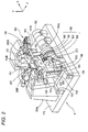
- FIG. 2 is a schematic structural view of a processing portion of an eyeglass lens processing apparatus according to the present invention.
- a carriage unit 100 is mounted on a base 170 of a processing apparatus body 1.
- a periphery of a processed lens LE held between lens chuck shafts (lens rotation shafts) 102L and 102R of a carriage 101 is processed while being pressed against a grindstone group 168 as a lens processing tool attached coaxially with a spindle (grindstone rotation axis) 161a.
- the grindstone group 168 includes: a rough grindstone 162 for glass; a bevel finishing grindstone 163 as a beveling tool for high-curve lenses; a bevel finishing grindstone 164 as a beveling tool for low-curve lenses; and a rough grindstone 165 for plastic.
- V groove (bevel groove) for low-curve lens bevel formation and a processing surface, for the bevel foot on the lens rear side and flat-processing, coupled to the V groove are integrally formed.
- the spindle 161a is disposed parallel to the lens chuck shafts 102L and 102R, and rotated by a motor 160.
- the lens chuck shaft 102L and the lens chuck shaft 102R are coaxially and rotatably held by a left arm 101L and a right arm 101R of the carriage 101, respectively.
- the lens chuck shaft 102R is moved toward the lens chuck shaft 102L side by a motor 110 attached to the right arm 101R.
- the lens chuck shafts 102R and 102L are rotated in synchronism with each other through a rotation transmission mechanism such as a gear by a motor 120 attached to the left arm 101L.
- These members constitute lens rotating unit.
- the carriage 101 is mounted on a support base 140 movable along shafts 103 and 104 extending in the x-axis direction, and is linearly moved in an x-axis direction (the axial direction of the lens chuck shafts) by rotation of a motor 145. These members constitute an x-axis direction movement unit. Shafts 156 and 157 extending in a y-axis direction (the direction in which the axis-to-axis distance between the lens chuck shafts 102L and 102R and the grindstone spindle 161a is varied) are fixed to the support base 140. The carriage 101 is mounted on the support base 140 so as to be movable in the y-axis direction along the shafts 156 and 157.
- a motor 150 for y-axis movement is fixed to the support base 140.
- the rotation of the motor 150 is transmitted to a ball screw 155 extending in the y-axis direction, and the carriage 101 is moved in the y-axis direction by the rotation of the ball screw 155.
- These members constitute y-axis direction movement unit.
- lens edge position measurement units 300F and 300R are provided above the carriage 101.
- the lens edge position measurement unit 300F has a tracing stylus that is in contact with the front surface of the lens LE
- the lens edge position measurement unit 300R has a tracing stylus that abuts on the rear surface of the lens LE.
- a chamfering mechanism 200 having a chamfering grindstone is disposed on the front side of the apparatus body 1.
- a known structure described in Japanese Unexamined Patent Application Publication No. 2001-315045 ( US 2002022436 ) is used.
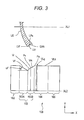
- FIG. 3 is a structural view of the grindstone group 168, and illustrates approximately a half of each grindstone with respect to an axis line XL2 of the center of rotation of the spindle 161a.
- the axis line XL2 of the spindle 161a is disposed parallel to an axis line XL1 of the lens chuck shafts 102L and 102R.
- the bevel finishing grindstone 164 for low-curve lenses includes: a V groove VLg for simultaneously forming a bevel LVr on the lens front side (hereinafter, referred to as front bevel) and a bevel LVr on the lens rear side (hereinafter, referred to as rear bevel); and a flat-processing surface VLk for forming the rear bevel foot LVrk coupled to the rear bevel (the rear side lens edge coupled to the rear bevel) and a flat surface for flat-processing.
- the depth of the V groove VLg is approximately 1 mm.
- the inclination angles (inclination angles with respect to the x-axis direction) of the processing surfaces of the V groove VLg for forming the front bevel LVf and the rear bevel LVr are both 35 degrees.
- the bevel finishing grindstone 163 for high-curve lenses include: a front beveling grindstone 163A having a processing surface Vf for forming the front bevel LVf; and a rear beveling grindstone 163B having a processing surface Vr for forming the rear bevel LVr and a processing surface Vrk for forming the rear bevel foot LVrk.
- the inclination angle ⁇ f of the processing surface Vf with respect to the x-axis direction is 30 degrees which is gentler than the angle of the front beveling inclined surface of the finishing grindstone 164. While the front beveling grindstone 163A and the rear beveling grindstone 163B are integrally formed, they may be separately provided.
- the outermost diameters of the front beveling grindstone 163A and the rear beveling grindstone 163B are the same as the outermost diameter of the rough grindstone 165. Thereby, the minimum processable lens diameter can be minimized by effectively using the processing surfaces of the rear beveling grindstone 163B.
- FIG. 4 is an enlarged view for explaining a first example of the processing surface Vr (first processing part) and the processing surface Vrk (second processing part) of the rear beveling grindstone 163B.
- the shapes of the processing surface Vr and the processing surface Vrk of FIG. 4 are illustrated as a cross-sectional view taken along a plane (x-y plane) including the axis line XL1 of the chuck axes 102L and 102R and the axis line XL2 of the spindle 161a.
- the point of border between the processing surface Vr and the processing surface Vrk is represented as the starting point Ps, and the endpoint of the processing surface Vrk in the direction toward the lens rear side (rightward in FIG. 4 ) is represented as Pe.
- a line extending in the x-axis direction through the point Ps (line parallel to the axis line XL2 of the lens chuck shafts) is represented as Xp.
- the inclination angle ⁇ r, with respect to the line Xp, of the processing surface Vr for rear bevel formation is larger than that of the V groove VLg of the grindstone 164 for low-curve lenses, and is set to 45 degrees.
- the bevels formed on a lens can be easily fitted on the rim of the eyeglass frame.
- the inclination angle, with respect to the direction of the line Xp, of the processing surface Vrk for rear bevel formation has, a value (path) that gradually increases at least in two steps from the starting point Ps to the endpoint Pe unlike the conventional constant one (straight line).
- the shape of the processing surface Vrk is considered as the distance from the line Xp, it is expressed as follows:
- the processing surface Vrk has a shape in which the distance yn gradually increases from the starting point Ps toward the endpoint Pe and the increase rate of the distance yn gradually increases at least in two steps toward the endpoint Pe.
- the processing surface Vrk has a curved shape in which the increase rate of the distance yn continuously gradually increases from the starting point Ps toward the endpoint Pe.
- the processing surface Vrk of FIG. 4 When the shape of the processing surface Vrk of FIG. 4 is expressed as the inclination angle with respect to the line Xp, the processing surface Vrk is formed so that the inclination angle ⁇ n between the point Pn and the next point Pn moved a minute distance therefrom gradually increases as the point Pn approaches the endpoint Pe. In other words, the processing surface Vrk is formed so that the differential value at the point Pn gradually increases as the point Pn approaches the endpoint Pe.
- the curved line of the path of the processing surface Vrk is an arc having a fixed radius R and in contact with the straight line La at the point Ps.
- the inclination angle ⁇ k (the increase rate of the distance yn) of the straight line La is set to a value where the bevel foot LVrk does not interfere with the surface Rmr, opposed to the edge, of the rim Rm (see FIGS. 5A and 5B ) when the processed lens is fitted on the rim Rm of an eyeglass frame.
- the inclination angle ⁇ k of the straight line La is also the inclination angle in the vicinity of the point Ps.
- the inclination angle in the vicinity of the point Ps be not less than 10 degrees.
- the bevel foot LVr is likely to interfere with the edge opposed surface Rmr when the lens is fitted in the frame.
- the inclination angle ⁇ k of the straight line La which is the inclination angle in the vicinity of the point Ps is 15 degrees which is the same as the inclination angle of the conventional processing surface Vrk shown in FIG. 1 .
- the inclination angle in the vicinity of the endpoint Pe is set to an angle or lower where the occurrence of so-called processing interference is suppressed in which the bevel foot LVr processed in the cross-sectional shape of the processing surface Vrk is excessively processed when another processing point of the lens is processed.
- the inclination angle in the vicinity of the endpoint Pe is not more than 60 degrees, the occurrence of the processing interference is substantially suppressed.
- the inclination angle in the vicinity of the endpoint Pe is not more than the inclination angle of the processing surface Vr. When the inclination angle is not more than this, the possibility of the occurrence of the processing interference is low as in the bevel formation. In the example of FIG.
- the path of the processing surface Vrk is an arc with a radius R of 20 mm.
- the path is an arc with a radius R of 20 mm and the width (the distance xn in the direction of the line Xp) of the processing surface Vrk is 5 mm, the inclination angle (the increase rate of the distance yn) in the vicinity of the endpoint Pe is approximately 29 degrees.
- FIGS. 5A and 5B are side views of a high-curve lens processed by the bevel finishing grindstone 163 having the processing surface Vrk shown in FIG. 4 .
- a partially enlarged view of an ear-side part is also illustrated.
- FIG. 5A shows a case where the lens edge is thick, and the rear bevel foot LVrk processed by the processing surface Vrk of FIG. 4 is shown by a solid line.
- the straight line La of the inclination angle ⁇ k indicates the processing surface of the conventional beveling grindstone shown in FIG. 1 , and the formation condition of the rear bevel foot in this case is indicated by a dotted line.
- the edge of the rear bevel foot LVrk is thinner by ⁇ Dx than that in the case of the conventional processing along the straight line La, and the thickness of the edge is inconspicuous as when a large chamfer is made.
- the edge LrE of the rear bevel foot LVrk is less sharp than that in the case of the processing along the straight line La, so that the edge LrE less frequently touches the user's cheek and this can provide the user with comfort.
- the sharpness at the part of the edge LrE is gentle, and this can provide the user with comfort. Further, when the bevel foot LVrk has a curved shape, the sharpness at the part of the edge LrE readily looks gentle.
- FIG. 5B shows a case where the lens edge is thin.
- the thickness of the edge when the rear bevel foot LVrk is viewed from the direction of the arrow A is not particularly different and the degree of the sharpness at the part of the edge LrE is not largely different, either.
- the lens is thin, the possibility of occurrence of these problems is low. If the inclination angle ⁇ k of the straight line La is large like that of the straight line Lb in order to thin the edge by ⁇ Dx equivalent to that in FIG.
- FIG. 6 is an explanatory view of a second example of the processing surface Vrk.
- This is an example in which the increase rate of the distance yn from the line Xp increases in two steps toward the endpoint Pe. That is, this is an example in which the inclination angle an of the processing surface Vrk with respect to the line Xp gradually increases in two steps. Assume that a point that is set between the starting point Ps and the endpoint Pe is Pm1.
- the inclination angle ⁇ a1 (the increase rate of the distance yn) in a first area Vrk1 between the starting point Ps and the point Pm1 is set as a value where the interference between the rear bevel foot LVr and the edge opposed surface Rmr of the rim Rm is avoided when the lens is fitted in the rim Rm of an eyeglass lens (see FIGS. 5A and 5B ).
- the inclination angle ⁇ a1 is not less than 10 degrees, preferably, approximately 15 degrees.
- the inclination angle ⁇ a2 of a second area Vrk2 between the point Pm1 and the endpoint Pe is larger than the inclination angle ⁇ a1.
- the processing surface Vrk is formed so that in the first area Vrk1, the distance yn of the point Pn on the path increases at a fixed rate and in the second area Vrk2, the distance yn of the point Pn on the path increases at a fixed rate higher than that in the case of the first area Vrkl.
- the edge thickness when viewed from the side can be reduced.
- the distance xm1 be longer than 1 mm and shorter than 3 mm.
- the distance xm1 is at least not more than 1 mm, as in the example of FIG. 5 , since the necessity of reducing the edge thickness when viewed from the side is low and the sharpness of the edge of the rear bevel foot is also low, the appearance of the rear bevel foot when viewed from the lens front side or the lens rear side can be enhanced.
- the inclination angle of the processing surface Vrk When the inclination angle of the processing surface Vrk is changed stepwise, the vicinity of the point Pm1 where the inclination angle is changed in the middle is curved. By doing this, the line caused by the change of the inclination angle is inconspicuous on the bevel foot of the processed lens, which enhances the appearance.
- the increase rate of the distance yn is not limited to two steps but may be more than that.
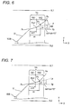
- FIG. 7 is an explanatory view of a third example of the processing surface Vrk.
- the processing surface Vrk in the first area Vrk1 from the starting point Ps to the midpoint Pm1, the processing surface Vrk has a straight line shape where the increase rate of the distance yn (the inclination angle) is constant.
- the processing surface Vrk In the second area Vrk2 from the point Pm1 to the endpoint Pe, the processing surface Vrk has a curved shape where the increase rate of the distance yn (the inclination angle) continuously gradually increases.
- the inclination angle ⁇ a1 in the first area Vrk1 between the starting point Ps and the point Pm1 is the same as that of the second example of FIG. 6 .
- This area also serves so as to reduce the thickness of the bevel foot viewed from the lens rear side (or the lens front side) in the case of thin-edge lenses.
- the second area Vrk2 in the second and third examples has a shape in which the distance yn is larger than the distance from the straight line La to the line Xp at least in the position where the distance xn is 3 mm.
- the increase rate (inclination angle) of the distance yn in the vicinity of the endpoint Pe is too large compared with that of the processing surface Vr, as in the case of bevel formation, the so-called processing interference in which the part processed in the cross-sectional shape of the processing surface Vrk is excessively processed when another processing point is processed is likely to occur. By doing as described above, the occurrence of this problem can be suppressed.
- FIG. 8 is a control block diagram of the present apparatus.
- PD value the distance between the right and left pupils of the user
- FPD value distance between the centers of the right and left rims of an eyeglass frame
- the height of the optical center with respect to the geometric center of the target lens shape is input by a key operation on a display 5.
- Processing conditions such as the lens material, the frame kind and the processing mode (beveling, flat-processing, grooving) are set by a key operation on the display 5.
- a bevel is to be formed on a high-curve lens
- a high curve mode is selected by a key 501.
- the lens edge position measurement units 300F and 300R are actuated, and the edge positions of the front and rear surfaces of the lens LE held by the lens chuck shafts 102R and 102L are measured based on the target lens shape data.
- the path of the bevel apex located on the lens edge is calculated by a control unit 50.
- the bevel apex path is calculated so as to be along the lens front surface curve and be in a position shifted by a predetermined amount (0.3 mm) rearward from the edge position of the lens front surface.
- a bevel simulation screen (not shown) is displayed on the display 5. On this screen, data for the adjustment of the amount of rearward shift of the bevel apex position from the lens front surface and data for the adjustment of the height of the bevel apex from the border point LPs between the rear bevel and the bevel foot (see FIG. 3 ) can be input.
- the motor 145 and the motor 150 are driven, and the lens chuck shafts 102L and 102R are moved so that the lens LE is located on the rough grindstone 165. Then, by controlling the positions, in the y-axis direction, of the lens chuck shafts 102L and 102R according to the rough-edging data obtained based on the target lens shape data, the periphery of the lens LE is roughed.
- the process shifts to beveling.
- the bevel finishing grindstone 163 for high-curve lenses is used, and the front bevel and the rear bevel are processed by the front beveling grindstone 163A and the rear beveling grindstone 163B, respectively.
- the front bevel is processed. Every predetermined rotation angle of the lens, the control unit 50 obtains processing data which is data on the movements in the x-axis direction and the y-axis direction when the bevel apex is in contact with the position of a predetermined diameter of the processing surface Vf of the front beveling grindstone 163A.
- the x-axis motor 145 and the y-axis motor 150 are controlled according to this processing data.
- the control unit 50 obtains the path of the border point LPs of the lens LE based on the data for the adjustment of the height of the bevel apex, and every predetermined rotation angle of the lens, obtains processing data which is data on the movements in the x-axis direction and the y-axis direction when the border point LPs is located at the border point Ps of the rear beveling grindstone 163B.
- processing data is data on the movements in the x-axis direction and the y-axis direction when the border point LPs is located at the border point Ps of the rear beveling grindstone 163B.
- the rear bevel foot LVrk of the lens is processed according to the edge thickness by the shape of the processing surface Vrk.
- the edge is processed so as to be thinner by ⁇ Dx than the conventional thickness in a condition close to when a large chamfer is made. For this reason, it is unnecessary to perform chamfering after beveling, so that the time for chamfering using the chamfering mechanism 200 is reduced.
- the shape of the processing surface Vrk is designed also for chamfering, the appearance of the edge can be enhanced.
- the operator In the chamfering by the chamfering mechanism 200, it is necessary for the operator to determine whether to perform chamfering or not, and it is also necessary for the operator to determine the amount of chamfer. To do this, the operator is required to have knowledge and experiment. When the degree of refractive power (edge thickness) is different between the lens for the right eye and the lens for the left eye, the determination of whether to perform chamfering or not and the amount of chamfer that results in good appearance is further difficult. On the contrary, when the shape of the processing surface Vrk is as described above, neither the setting of chamfering nor a difficult determination is required of the operator, so that the chamfering process is simplified and the edge can be processed so as to be thin and look nice according to the edge thickness.
- the shapes of the processing surface Vrk as shown in FIGS. 4 , 6 and 7 are not limited to the bevel finishing grindstone 163 for high-curve lenses, but may be applied to the bevel finishing grindstone 164 for low-curve lenses.
- the processing surface Vrk for rear bevel foot formation is formed with the inclination angle ⁇ k of the straight line La being substantially zero (or a slight angle such as 2.5 degrees).
- the beveling tool is not limited to the grindstone, but a tool such as a cutter or an end mill having the processing parts shown in FIG. 4 , etc. is applicable.
- FIG. 9 shows an example in which a small-diameter grindstone is used as the beveling tool for high-curve lenses and the small-diameter beveling grindstone is attached to a spindle different from the spindle (grindstone rotation axis) 161a to which the bevel finishing grindstone 164, the rough grindstone 165 and the like are attached.
- a beveling grindstone 500 is provided with a first processing surface 500Vr for rear bevel formation, a second processing surface 500Vrk for rear bevel foot formation and a third processing surface 500Vf for front bevel formation.
- the first processing surface 500Vr and the third processing surface 500Vf for front bevel formation are separated from each other, and are disposed on opposite ends of the grindstone 500.
- the grindstone 500 is attached to a spindle 501 different from the spindle (grindstone rotation axis) 161a.
- the spindle 501 and the rotation mechanism one same as the mechanism 200 shown in FIG. 2 is used.
- the spindle 501 is rotated by a motor (not shown) of the mechanism 200.
- the axis line L3 of the spindle 501 is not parallel to the axis line XL1 of the lens chuck shafts 102R and 102L but is inclined an angle 6 as in the case where the chamfering grindstone of the mechanism 200 is disposed.
- the angle ⁇ is, for example, approximately 10 degrees.
- Xp represents a line parallel to the axis line XL1 of the lens chuck shafts and passing through the border point Ps between the processing surface 500Vr and the processing surface 500Vrk. While the axis line L3 of the spindle 501 is inclined the angle ⁇ with respect to the line Xp (x direction), the inclination angle ⁇ r of the processing surface 500Vr and the inclination angle ⁇ f of the processing surface 500Vf with respect to the line Xp are set to 45 degrees and 30 degrees, respectively, as in the case of FIG. 4 .
- the processing surface 500Vrk for rear bevel foot formation has a shape in which the inclination angle with respect to the direction of the line Xp gradually increases at least in two steps from the starting point Ps to the endpoint Pe as in FIGS. 4 , 6 and 7 . That is, the processing surface 500Vrk has a shape in which the increase rate of the distance yn from the point Pn to the line Xp gradually increases at least in two steps from the starting porint Ps to the endpoint Pe.
- the example of FIG. 9 has a curved shape in which the inclination angle (the increase rate of the distance yn) of the processing surface Vrk continuously gradually increases from the starting point Ps toward the endpoint Pe like the first example of FIG. 4 .
- the offset corresponding to the inclination angle ⁇ of the axis line L3 of the grindstone rotation axis is calculated in forming the processing surface 500Vrk.
Landscapes
- Engineering & Computer Science (AREA)
- Chemical & Material Sciences (AREA)
- Ceramic Engineering (AREA)
- Inorganic Chemistry (AREA)
- Mechanical Engineering (AREA)
- Grinding And Polishing Of Tertiary Curved Surfaces And Surfaces With Complex Shapes (AREA)
- Eyeglasses (AREA)
Applications Claiming Priority (1)
| Application Number | Priority Date | Filing Date | Title |
|---|---|---|---|
| JP2009162154A JP5372628B2 (ja) | 2009-07-08 | 2009-07-08 | 眼鏡レンズ加工装置及び該装置に使用されるヤゲン加工具 |
Publications (3)
| Publication Number | Publication Date |
|---|---|
| EP2275229A2 EP2275229A2 (en) | 2011-01-19 |
| EP2275229A3 EP2275229A3 (en) | 2014-06-11 |
| EP2275229B1 true EP2275229B1 (en) | 2016-01-06 |
Family
ID=42751981
Family Applications (1)
| Application Number | Title | Priority Date | Filing Date |
|---|---|---|---|
| EP10007064.8A Not-in-force EP2275229B1 (en) | 2009-07-08 | 2010-07-08 | Eyeglass lens processing apparatus |
Country Status (4)
| Country | Link |
|---|---|
| US (1) | US8684795B2 (enExample) |
| EP (1) | EP2275229B1 (enExample) |
| JP (1) | JP5372628B2 (enExample) |
| CN (1) | CN101947753B (enExample) |
Families Citing this family (3)
| Publication number | Priority date | Publication date | Assignee | Title |
|---|---|---|---|---|
| JP5899978B2 (ja) * | 2012-02-03 | 2016-04-06 | 株式会社ニデック | 眼鏡レンズ加工装置 |
| JP6766400B2 (ja) * | 2016-03-28 | 2020-10-14 | 株式会社ニデック | 眼鏡レンズ加工装置、及び眼鏡レンズ加工プログラム |
| JP2025108824A (ja) * | 2024-01-11 | 2025-07-24 | ホヤ レンズ タイランド リミテッド | 眼鏡レンズの製造方法および製造装置 |
Family Cites Families (37)
| Publication number | Priority date | Publication date | Assignee | Title |
|---|---|---|---|---|
| US3353303A (en) * | 1964-11-13 | 1967-11-21 | Ait Ind Inc | Art of edging |
| US4179851A (en) * | 1978-01-24 | 1979-12-25 | Coburn Optical Industries, Inc. | Apparatus for edging ophthalmic lenses |
| US4176498A (en) * | 1978-02-21 | 1979-12-04 | Ait Industries, Inc. | Apparatus for edging lenses |
| US4286415A (en) * | 1979-03-12 | 1981-09-01 | Ait Industries, Inc. | Method of edging lenses |
| US4233784A (en) * | 1979-03-12 | 1980-11-18 | Ait Industries, Inc. | Lens edging apparatus |
| FR2553323B1 (fr) * | 1983-10-18 | 1986-07-25 | Essilor Int | Procede et machine pour le biseautage ou rainurage d'une lentille ophtalmique |
| US4720942A (en) * | 1986-03-10 | 1988-01-26 | Miller Jack D | Apparatus for abrading contact lens edges |
| FR2611560B1 (fr) * | 1987-03-05 | 1992-10-02 | Briot Int | Perfectionnements aux machines a meuler et a biseauter les verres ophtalmiques |
| GB8816182D0 (en) * | 1988-07-07 | 1988-08-10 | Berkshire Ophthalmic Lab Ltd | Method & apparatus for grinding lenses |
| FR2682628B1 (fr) * | 1991-10-21 | 1996-01-05 | Buchmann Optical Eng | Perfectionnements aux machines a meuler et a biseauter les verres ophtalmiques. |
| FR2691663B1 (fr) * | 1992-05-26 | 1996-10-11 | Essilor Int | Procede de ravivage de meules, disque et machine pour sa mise en óoeuvre. |
| FR2697769B1 (fr) * | 1992-11-10 | 1995-01-13 | Buchmann Optical Eng | Machine automatique pour meuler et biseauter les verres ophtalmiques. |
| DE4320934C2 (de) * | 1993-06-24 | 1995-04-20 | Wernicke & Co Gmbh | Brillenglasrandschleifmaschine |
| JPH09277148A (ja) * | 1996-04-17 | 1997-10-28 | Topcon Corp | レンズ周縁研削方法及びその装置 |
| JP3667483B2 (ja) * | 1997-02-10 | 2005-07-06 | 株式会社ニデック | レンズ研削加工装置 |
| EP0894568B1 (en) * | 1997-08-01 | 2008-09-10 | Nidek Co., Ltd. | Method and apparatus for grinding eyeglass lenses |
| JP3730406B2 (ja) * | 1998-04-30 | 2006-01-05 | 株式会社ニデック | 眼鏡レンズ加工装置 |
| US6328630B1 (en) * | 1998-10-05 | 2001-12-11 | Hoya Corporation | Eyeglass lens end face machining method |
| JP4360764B2 (ja) * | 2000-04-28 | 2009-11-11 | 株式会社トプコン | 眼鏡レンズのレンズ周縁加工方法、レンズ周縁加工装置及び眼鏡レンズ |
| JP3942802B2 (ja) | 2000-04-28 | 2007-07-11 | 株式会社ニデック | 眼鏡レンズ加工装置 |
| JP3916445B2 (ja) * | 2001-11-08 | 2007-05-16 | 株式会社ニデック | 眼鏡レンズ加工装置 |
| FR2838363B1 (fr) * | 2002-04-12 | 2004-12-24 | Essilor Int | Procede de meulage d'une lentille ophtalmique comportant une etape de releve sans contact |
| JP2004058203A (ja) * | 2002-07-29 | 2004-02-26 | Hoya Corp | レンズ加工方法及びレンズ加工装置並びにレンズ |
| FR2852878B1 (fr) * | 2003-03-27 | 2006-09-29 | Briot Int | Machine de meulage de verres optiques. |
| JP4131842B2 (ja) | 2003-08-29 | 2008-08-13 | 株式会社ニデック | 眼鏡レンズ加工装置 |
| US8241534B2 (en) * | 2004-03-09 | 2012-08-14 | Hoya Corporation | Spectacle lens manufacturing method and spectacle lens manufacturing system |
| FR2885063B1 (fr) * | 2005-04-29 | 2007-07-06 | Essilor Int | Procede et dispositif de travail de la peripherie d'une lentille ophtalmique de lunettes |
| JP4397367B2 (ja) * | 2005-10-11 | 2010-01-13 | 株式会社ニデック | レンズ研削加工装置 |
| JP4544180B2 (ja) | 2006-03-01 | 2010-09-15 | ブラザー工業株式会社 | 画像形成装置 |
| JP2007319984A (ja) | 2006-05-31 | 2007-12-13 | Nidek Co Ltd | 眼鏡レンズ周縁加工装置 |
| FR2904703B1 (fr) * | 2006-08-04 | 2008-12-12 | Essilor Int | Paire de lunettes ophtalmiques et procede de formation d'une nervure peripherique d'emboitement sur le chant d'une lentille |
| JP4975469B2 (ja) | 2007-02-02 | 2012-07-11 | 株式会社ニデック | 眼鏡レンズ加工装置 |
| JP5073345B2 (ja) * | 2007-03-30 | 2012-11-14 | 株式会社ニデック | 眼鏡レンズ加工装置 |
| JP5405720B2 (ja) * | 2007-03-30 | 2014-02-05 | 株式会社ニデック | 眼鏡レンズ加工装置 |
| JP5265127B2 (ja) * | 2007-03-30 | 2013-08-14 | 株式会社ニデック | 眼鏡レンズ加工装置 |
| JP5134346B2 (ja) * | 2007-11-30 | 2013-01-30 | 株式会社ニデック | 眼鏡レンズ周縁加工装置 |
| JP5209358B2 (ja) * | 2008-03-31 | 2013-06-12 | 株式会社ニデック | ヤゲン軌跡設定方法及び眼鏡レンズ加工装置 |
-
2009
- 2009-07-08 JP JP2009162154A patent/JP5372628B2/ja not_active Expired - Fee Related
-
2010
- 2010-07-07 CN CN201010224937.9A patent/CN101947753B/zh not_active Expired - Fee Related
- 2010-07-07 US US12/831,809 patent/US8684795B2/en not_active Expired - Fee Related
- 2010-07-08 EP EP10007064.8A patent/EP2275229B1/en not_active Not-in-force
Also Published As
| Publication number | Publication date |
|---|---|
| JP5372628B2 (ja) | 2013-12-18 |
| CN101947753A (zh) | 2011-01-19 |
| JP2011016191A (ja) | 2011-01-27 |
| US8684795B2 (en) | 2014-04-01 |
| US20110009036A1 (en) | 2011-01-13 |
| EP2275229A3 (en) | 2014-06-11 |
| CN101947753B (zh) | 2014-10-15 |
| EP2275229A2 (en) | 2011-01-19 |
Similar Documents
| Publication | Publication Date | Title |
|---|---|---|
| JP5134346B2 (ja) | 眼鏡レンズ周縁加工装置 | |
| JP5405720B2 (ja) | 眼鏡レンズ加工装置 | |
| JP5073345B2 (ja) | 眼鏡レンズ加工装置 | |
| EP2191935B1 (en) | Eyeglass lens processing apparatus for processing periphery of eyeglass lens | |
| EP1815941B1 (en) | Eyeglass lens processing apparatus | |
| EP2106879B1 (en) | Eyeglass lens processing apparatus | |
| JP5179172B2 (ja) | 眼鏡レンズ研削加工装置 | |
| JP4975469B2 (ja) | 眼鏡レンズ加工装置 | |
| EP2275229B1 (en) | Eyeglass lens processing apparatus | |
| JP5265127B2 (ja) | 眼鏡レンズ加工装置 | |
| JP2006189659A (ja) | 眼鏡レンズ加工装置 | |
| JP6390103B2 (ja) | レンズ周縁加工装置、及びレンズ周縁加工プログラム | |
| JP4865462B2 (ja) | 眼鏡レンズ加工装置および眼鏡レンズの加工方法 | |
| JP7735654B2 (ja) | 眼鏡レンズ加工装置および眼鏡レンズ加工制御プログラム | |
| JP4421470B2 (ja) | レンズ研削加工装置のレイアウト設定装置 |
Legal Events
| Date | Code | Title | Description |
|---|---|---|---|
| PUAI | Public reference made under article 153(3) epc to a published international application that has entered the european phase |
Free format text: ORIGINAL CODE: 0009012 |
|
| AK | Designated contracting states |
Kind code of ref document: A2 Designated state(s): AL AT BE BG CH CY CZ DE DK EE ES FI FR GB GR HR HU IE IS IT LI LT LU LV MC MK MT NL NO PL PT RO SE SI SK SM TR |
|
| AX | Request for extension of the european patent |
Extension state: BA ME RS |
|
| PUAL | Search report despatched |
Free format text: ORIGINAL CODE: 0009013 |
|
| AK | Designated contracting states |
Kind code of ref document: A3 Designated state(s): AL AT BE BG CH CY CZ DE DK EE ES FI FR GB GR HR HU IE IS IT LI LT LU LV MC MK MT NL NO PL PT RO SE SI SK SM TR |
|
| AX | Request for extension of the european patent |
Extension state: BA ME RS |
|
| RIC1 | Information provided on ipc code assigned before grant |
Ipc: B24B 9/14 20060101AFI20140502BHEP |
|
| 17P | Request for examination filed |
Effective date: 20141204 |
|
| RBV | Designated contracting states (corrected) |
Designated state(s): AL AT BE BG CH CY CZ DE DK EE ES FI FR GB GR HR HU IE IS IT LI LT LU LV MC MK MT NL NO PL PT RO SE SI SK SM TR |
|
| GRAP | Despatch of communication of intention to grant a patent |
Free format text: ORIGINAL CODE: EPIDOSNIGR1 |
|
| INTG | Intention to grant announced |
Effective date: 20150720 |
|
| GRAS | Grant fee paid |
Free format text: ORIGINAL CODE: EPIDOSNIGR3 |
|
| GRAA | (expected) grant |
Free format text: ORIGINAL CODE: 0009210 |
|
| AK | Designated contracting states |
Kind code of ref document: B1 Designated state(s): AL AT BE BG CH CY CZ DE DK EE ES FI FR GB GR HR HU IE IS IT LI LT LU LV MC MK MT NL NO PL PT RO SE SI SK SM TR |
|
| REG | Reference to a national code |
Ref country code: GB Ref legal event code: FG4D |
|
| REG | Reference to a national code |
Ref country code: CH Ref legal event code: EP |
|
| REG | Reference to a national code |
Ref country code: IE Ref legal event code: FG4D |
|
| REG | Reference to a national code |
Ref country code: AT Ref legal event code: REF Ref document number: 768454 Country of ref document: AT Kind code of ref document: T Effective date: 20160215 |
|
| REG | Reference to a national code |
Ref country code: DE Ref legal event code: R096 Ref document number: 602010029813 Country of ref document: DE |
|
| REG | Reference to a national code |
Ref country code: LT Ref legal event code: MG4D |
|
| REG | Reference to a national code |
Ref country code: NL Ref legal event code: MP Effective date: 20160106 |
|
| REG | Reference to a national code |
Ref country code: AT Ref legal event code: MK05 Ref document number: 768454 Country of ref document: AT Kind code of ref document: T Effective date: 20160106 |
|
| PG25 | Lapsed in a contracting state [announced via postgrant information from national office to epo] |
Ref country code: NL Free format text: LAPSE BECAUSE OF FAILURE TO SUBMIT A TRANSLATION OF THE DESCRIPTION OR TO PAY THE FEE WITHIN THE PRESCRIBED TIME-LIMIT Effective date: 20160106 |
|
| PG25 | Lapsed in a contracting state [announced via postgrant information from national office to epo] |
Ref country code: ES Free format text: LAPSE BECAUSE OF FAILURE TO SUBMIT A TRANSLATION OF THE DESCRIPTION OR TO PAY THE FEE WITHIN THE PRESCRIBED TIME-LIMIT Effective date: 20160106 Ref country code: HR Free format text: LAPSE BECAUSE OF FAILURE TO SUBMIT A TRANSLATION OF THE DESCRIPTION OR TO PAY THE FEE WITHIN THE PRESCRIBED TIME-LIMIT Effective date: 20160106 Ref country code: NO Free format text: LAPSE BECAUSE OF FAILURE TO SUBMIT A TRANSLATION OF THE DESCRIPTION OR TO PAY THE FEE WITHIN THE PRESCRIBED TIME-LIMIT Effective date: 20160406 Ref country code: GR Free format text: LAPSE BECAUSE OF FAILURE TO SUBMIT A TRANSLATION OF THE DESCRIPTION OR TO PAY THE FEE WITHIN THE PRESCRIBED TIME-LIMIT Effective date: 20160407 Ref country code: FI Free format text: LAPSE BECAUSE OF FAILURE TO SUBMIT A TRANSLATION OF THE DESCRIPTION OR TO PAY THE FEE WITHIN THE PRESCRIBED TIME-LIMIT Effective date: 20160106 Ref country code: IT Free format text: LAPSE BECAUSE OF FAILURE TO SUBMIT A TRANSLATION OF THE DESCRIPTION OR TO PAY THE FEE WITHIN THE PRESCRIBED TIME-LIMIT Effective date: 20160106 |
|
| PG25 | Lapsed in a contracting state [announced via postgrant information from national office to epo] |
Ref country code: LT Free format text: LAPSE BECAUSE OF FAILURE TO SUBMIT A TRANSLATION OF THE DESCRIPTION OR TO PAY THE FEE WITHIN THE PRESCRIBED TIME-LIMIT Effective date: 20160106 Ref country code: AT Free format text: LAPSE BECAUSE OF FAILURE TO SUBMIT A TRANSLATION OF THE DESCRIPTION OR TO PAY THE FEE WITHIN THE PRESCRIBED TIME-LIMIT Effective date: 20160106 Ref country code: LV Free format text: LAPSE BECAUSE OF FAILURE TO SUBMIT A TRANSLATION OF THE DESCRIPTION OR TO PAY THE FEE WITHIN THE PRESCRIBED TIME-LIMIT Effective date: 20160106 Ref country code: SE Free format text: LAPSE BECAUSE OF FAILURE TO SUBMIT A TRANSLATION OF THE DESCRIPTION OR TO PAY THE FEE WITHIN THE PRESCRIBED TIME-LIMIT Effective date: 20160106 Ref country code: IS Free format text: LAPSE BECAUSE OF FAILURE TO SUBMIT A TRANSLATION OF THE DESCRIPTION OR TO PAY THE FEE WITHIN THE PRESCRIBED TIME-LIMIT Effective date: 20160506 Ref country code: PT Free format text: LAPSE BECAUSE OF FAILURE TO SUBMIT A TRANSLATION OF THE DESCRIPTION OR TO PAY THE FEE WITHIN THE PRESCRIBED TIME-LIMIT Effective date: 20160506 Ref country code: PL Free format text: LAPSE BECAUSE OF FAILURE TO SUBMIT A TRANSLATION OF THE DESCRIPTION OR TO PAY THE FEE WITHIN THE PRESCRIBED TIME-LIMIT Effective date: 20160106 |
|
| REG | Reference to a national code |
Ref country code: DE Ref legal event code: R097 Ref document number: 602010029813 Country of ref document: DE |
|
| PG25 | Lapsed in a contracting state [announced via postgrant information from national office to epo] |
Ref country code: EE Free format text: LAPSE BECAUSE OF FAILURE TO SUBMIT A TRANSLATION OF THE DESCRIPTION OR TO PAY THE FEE WITHIN THE PRESCRIBED TIME-LIMIT Effective date: 20160106 Ref country code: DK Free format text: LAPSE BECAUSE OF FAILURE TO SUBMIT A TRANSLATION OF THE DESCRIPTION OR TO PAY THE FEE WITHIN THE PRESCRIBED TIME-LIMIT Effective date: 20160106 |
|
| PLBE | No opposition filed within time limit |
Free format text: ORIGINAL CODE: 0009261 |
|
| STAA | Information on the status of an ep patent application or granted ep patent |
Free format text: STATUS: NO OPPOSITION FILED WITHIN TIME LIMIT |
|
| PG25 | Lapsed in a contracting state [announced via postgrant information from national office to epo] |
Ref country code: SM Free format text: LAPSE BECAUSE OF FAILURE TO SUBMIT A TRANSLATION OF THE DESCRIPTION OR TO PAY THE FEE WITHIN THE PRESCRIBED TIME-LIMIT Effective date: 20160106 Ref country code: SK Free format text: LAPSE BECAUSE OF FAILURE TO SUBMIT A TRANSLATION OF THE DESCRIPTION OR TO PAY THE FEE WITHIN THE PRESCRIBED TIME-LIMIT Effective date: 20160106 Ref country code: RO Free format text: LAPSE BECAUSE OF FAILURE TO SUBMIT A TRANSLATION OF THE DESCRIPTION OR TO PAY THE FEE WITHIN THE PRESCRIBED TIME-LIMIT Effective date: 20160106 Ref country code: CZ Free format text: LAPSE BECAUSE OF FAILURE TO SUBMIT A TRANSLATION OF THE DESCRIPTION OR TO PAY THE FEE WITHIN THE PRESCRIBED TIME-LIMIT Effective date: 20160106 |
|
| 26N | No opposition filed |
Effective date: 20161007 |
|
| PG25 | Lapsed in a contracting state [announced via postgrant information from national office to epo] |
Ref country code: BE Free format text: LAPSE BECAUSE OF FAILURE TO SUBMIT A TRANSLATION OF THE DESCRIPTION OR TO PAY THE FEE WITHIN THE PRESCRIBED TIME-LIMIT Effective date: 20160106 |
|
| REG | Reference to a national code |
Ref country code: DE Ref legal event code: R119 Ref document number: 602010029813 Country of ref document: DE |
|
| PG25 | Lapsed in a contracting state [announced via postgrant information from national office to epo] |
Ref country code: BG Free format text: LAPSE BECAUSE OF FAILURE TO SUBMIT A TRANSLATION OF THE DESCRIPTION OR TO PAY THE FEE WITHIN THE PRESCRIBED TIME-LIMIT Effective date: 20160406 Ref country code: SI Free format text: LAPSE BECAUSE OF FAILURE TO SUBMIT A TRANSLATION OF THE DESCRIPTION OR TO PAY THE FEE WITHIN THE PRESCRIBED TIME-LIMIT Effective date: 20160106 |
|
| REG | Reference to a national code |
Ref country code: CH Ref legal event code: PL |
|
| GBPC | Gb: european patent ceased through non-payment of renewal fee |
Effective date: 20160708 |
|
| PG25 | Lapsed in a contracting state [announced via postgrant information from national office to epo] |
Ref country code: MC Free format text: LAPSE BECAUSE OF FAILURE TO SUBMIT A TRANSLATION OF THE DESCRIPTION OR TO PAY THE FEE WITHIN THE PRESCRIBED TIME-LIMIT Effective date: 20160106 |
|
| PG25 | Lapsed in a contracting state [announced via postgrant information from national office to epo] |
Ref country code: DE Free format text: LAPSE BECAUSE OF NON-PAYMENT OF DUE FEES Effective date: 20170201 Ref country code: CH Free format text: LAPSE BECAUSE OF NON-PAYMENT OF DUE FEES Effective date: 20160731 Ref country code: FR Free format text: LAPSE BECAUSE OF NON-PAYMENT OF DUE FEES Effective date: 20160801 Ref country code: LI Free format text: LAPSE BECAUSE OF NON-PAYMENT OF DUE FEES Effective date: 20160731 |
|
| REG | Reference to a national code |
Ref country code: FR Ref legal event code: ST Effective date: 20170331 |
|
| REG | Reference to a national code |
Ref country code: IE Ref legal event code: MM4A |
|
| PG25 | Lapsed in a contracting state [announced via postgrant information from national office to epo] |
Ref country code: GB Free format text: LAPSE BECAUSE OF NON-PAYMENT OF DUE FEES Effective date: 20160708 |
|
| PG25 | Lapsed in a contracting state [announced via postgrant information from national office to epo] |
Ref country code: IE Free format text: LAPSE BECAUSE OF NON-PAYMENT OF DUE FEES Effective date: 20160708 |
|
| PG25 | Lapsed in a contracting state [announced via postgrant information from national office to epo] |
Ref country code: LU Free format text: LAPSE BECAUSE OF NON-PAYMENT OF DUE FEES Effective date: 20160708 |
|
| PG25 | Lapsed in a contracting state [announced via postgrant information from national office to epo] |
Ref country code: CY Free format text: LAPSE BECAUSE OF FAILURE TO SUBMIT A TRANSLATION OF THE DESCRIPTION OR TO PAY THE FEE WITHIN THE PRESCRIBED TIME-LIMIT Effective date: 20160106 Ref country code: HU Free format text: LAPSE BECAUSE OF FAILURE TO SUBMIT A TRANSLATION OF THE DESCRIPTION OR TO PAY THE FEE WITHIN THE PRESCRIBED TIME-LIMIT; INVALID AB INITIO Effective date: 20100708 |
|
| PG25 | Lapsed in a contracting state [announced via postgrant information from national office to epo] |
Ref country code: MT Free format text: LAPSE BECAUSE OF NON-PAYMENT OF DUE FEES Effective date: 20160731 Ref country code: MK Free format text: LAPSE BECAUSE OF FAILURE TO SUBMIT A TRANSLATION OF THE DESCRIPTION OR TO PAY THE FEE WITHIN THE PRESCRIBED TIME-LIMIT Effective date: 20160106 Ref country code: TR Free format text: LAPSE BECAUSE OF FAILURE TO SUBMIT A TRANSLATION OF THE DESCRIPTION OR TO PAY THE FEE WITHIN THE PRESCRIBED TIME-LIMIT Effective date: 20160106 |
|
| PG25 | Lapsed in a contracting state [announced via postgrant information from national office to epo] |
Ref country code: AL Free format text: LAPSE BECAUSE OF FAILURE TO SUBMIT A TRANSLATION OF THE DESCRIPTION OR TO PAY THE FEE WITHIN THE PRESCRIBED TIME-LIMIT Effective date: 20160106 |