EP2274875B1 - Skalierbares wlan-gateway - Google Patents
Skalierbares wlan-gateway Download PDFInfo
- Publication number
- EP2274875B1 EP2274875B1 EP08874187.1A EP08874187A EP2274875B1 EP 2274875 B1 EP2274875 B1 EP 2274875B1 EP 08874187 A EP08874187 A EP 08874187A EP 2274875 B1 EP2274875 B1 EP 2274875B1
- Authority
- EP
- European Patent Office
- Prior art keywords
- mobile station
- wlan
- network
- client terminal
- processor
- Prior art date
- Legal status (The legal status is an assumption and is not a legal conclusion. Google has not performed a legal analysis and makes no representation as to the accuracy of the status listed.)
- Active
Links
Images


Classifications
-
- H—ELECTRICITY
- H04—ELECTRIC COMMUNICATION TECHNIQUE
- H04L—TRANSMISSION OF DIGITAL INFORMATION, e.g. TELEGRAPHIC COMMUNICATION
- H04L12/00—Data switching networks
- H04L12/28—Data switching networks characterised by path configuration, e.g. LAN [Local Area Networks] or WAN [Wide Area Networks]
-
- H—ELECTRICITY
- H04—ELECTRIC COMMUNICATION TECHNIQUE
- H04W—WIRELESS COMMUNICATION NETWORKS
- H04W88/00—Devices specially adapted for wireless communication networks, e.g. terminals, base stations or access point devices
- H04W88/02—Terminal devices
- H04W88/06—Terminal devices adapted for operation in multiple networks or having at least two operational modes, e.g. multi-mode terminals
-
- H—ELECTRICITY
- H04—ELECTRIC COMMUNICATION TECHNIQUE
- H04W—WIRELESS COMMUNICATION NETWORKS
- H04W12/00—Security arrangements; Authentication; Protecting privacy or anonymity
- H04W12/06—Authentication
-
- H—ELECTRICITY
- H04—ELECTRIC COMMUNICATION TECHNIQUE
- H04W—WIRELESS COMMUNICATION NETWORKS
- H04W72/00—Local resource management
- H04W72/04—Wireless resource allocation
-
- H—ELECTRICITY
- H04—ELECTRIC COMMUNICATION TECHNIQUE
- H04W—WIRELESS COMMUNICATION NETWORKS
- H04W84/00—Network topologies
- H04W84/02—Hierarchically pre-organised networks, e.g. paging networks, cellular networks, WLAN [Wireless Local Area Network] or WLL [Wireless Local Loop]
- H04W84/10—Small scale networks; Flat hierarchical networks
- H04W84/12—WLAN [Wireless Local Area Networks]
-
- H—ELECTRICITY
- H04—ELECTRIC COMMUNICATION TECHNIQUE
- H04W—WIRELESS COMMUNICATION NETWORKS
- H04W84/00—Network topologies
- H04W84/18—Self-organising networks, e.g. ad-hoc networks or sensor networks
-
- H—ELECTRICITY
- H04—ELECTRIC COMMUNICATION TECHNIQUE
- H04W—WIRELESS COMMUNICATION NETWORKS
- H04W88/00—Devices specially adapted for wireless communication networks, e.g. terminals, base stations or access point devices
- H04W88/02—Terminal devices
- H04W88/04—Terminal devices adapted for relaying to or from another terminal or user
Definitions
- a broadband connection means a connection capable of transmitting traffic, in good network conditions, faster than a V.90 modem can, or faster than 64 kilobits per second.
- Wireless broadband modems can be used to couple personal computers or client terminals to the internet in places where wired internet connections or local-area networks are not available.
- Prior art wireless broadband modems exhibit certain problems. For instance, sharing a single wireless broadband connection among several users (client terminals) is awkward at best. Normally this requires setting up one of several client terminals as a master terminal that provides the internet connection to the remaining client terminals. This process consumes resources of the master terminal and the client terminals cannot operate without the master.
- the difficulty of sharing a single wireless broadband connection among several users is understandable in view of the fact that most wireless broadband modems are given or sold at a nominal cost by mobile network operators in connection with a network subscription.
- the network operators' obvious desire is to sell a subscription to each user instead of sharing a single connection among several users.
- Another problem of prior art wireless broadband modems is the fact that most of them are "wireless" only towards the mobile network and the connection to the client terminal takes place via a USB cable.
- the wired connection is actually a benefit in connection with fixed client terminals, such as home computers, because the wired connection can also supply power to the wireless broadband modem, but in connection with mobile client terminals, the wired nature of the USB connection is a definite handicap.
- Yet another problem is that the bandwidth provided by the mobile station and access network may be insufficient, particularly when several client terminals share a single wireless broadband connection.
- US 20030035397 A1 disclosed a system, device and computer readable medium that monitors and reconfigures a LAN by a WAN operator is provided.
- a telecommunications operator monitors and manages devices and/or applications communicating with a wireless device, such as cellular telephone.
- a telecommunication operator adds LAN network services to microrouter 404 in a cellular telephone without user intervention.
- the cellular telephone has a BluetoothTM processor and transceiver.
- microrouter 404 includes a BluetoothTM LAN Access Profile software component, routing software component, PPP server software component and a NAT software component.
- microrouter 404 includes hooks and interfaces for adding other network services, such as a BluetoothTM Terminal Pairing Management software component, a VPN software component, Firewall component, Statistics software component, Link Optimization software component, LAN reverse firewall software component, Terminal Flashing software component, SMS software component, SLV and SLE software component and a Device Resources software component.
- a BluetoothTM Terminal Pairing Management software component such as a BluetoothTM Terminal Pairing Management software component, a VPN software component, Firewall component, Statistics software component, Link Optimization software component, LAN reverse firewall software component, Terminal Flashing software component, SMS software component, SLV and SLE software component and a Device Resources software component.
- US 20050078624 A1 disclosed a wireless network software access point (AP) integrated into a wireless device allows a wireless network to be configured automatically and dynamically maintained with minimal user intervention.
- Such automatic configuration includes: whether to configure the Soft AP enabled device to be an AP Node or a Station Node; specifics of wireless radio link configuration, routing or bridging relationships with other networking devices attached to the host-computing device; and firewall configuration.
- Such automatic configurations are based on the automatic detection of the network environment attached to the Soft AP enabled device.
- the automatic configurations may also be based on the intelligent interactions among different Soft AP enabled devices in the wireless network, which often includes devices with and without Soft AP functionalities.
- WO2007/096884 A2 disclosed a method for providing a wireless Internet connection to WiFi-enabled devices (STAs) comprising: wirelessly connecting a first STA to the Internet through a first AP with a first SSID; remaining connected to the first Access Point (AP), the first STA creates a software-based wireless AP with a second SSID for wirelessly connecting other STAs to the Internet through the first STA.
- a software module running on the first STA allows a second STA a wide access to the Internet only if the second STA has a copy of the software module running installed and active therein.
- a method for configuring STAs to connect to a wireless network comprising: a customer first connects a STA by wire to its network; a software on the STA copies to the STA the security information gained through the wired connection, thus setting the security parameters for the STA.
- An object of the invention is to develop a method, an apparatus and software products so as to alleviate one or, more of the roblems identified above.
- the object is achieved by a mobile station, a software carrier and a method as defined in the attached independent claims.
- the dependent claims and the drawings with their associated descriptions relate to specific embodiments.
- An aspect of the invention is a mobile station as set forth in claim 1.
- aspects of the invention include a method for operating the above-specified mobile station claim 6, and a software carrier comprising a software application for a mobile station claim 5.
- An example useful to understand the invention includes a multiplexing/demultiplexing computer for multiplexing (combining) data packets from the above-specified multiple simultaneous transmission paths to an internet host, and for demultiplexing (splitting) data packets arriving from the internet host to the multiple simultaneous transmission paths. Later in this description the multiplexing/demultiplexing computer is colloquially called a "ShareMachine".
- the mobile station further comprises means for receiving, installing and executing downloadable programs and the inventive gateway application is a downloadable application.
- the inventive gateway application is a downloadable application.
- the gateway application further comprises a code portion to redirect a first HTTP page request from each mobile station during an internet session to a predetermined internet address. Redirecting the mobile station's first HTTP page request during an internet session provides the owner of the predetermined internet address with the benefit that the mobile station user must begin an internet session via the predetermined internet address. That address may contain useful information or advertisements, for example.
- Yet another specific example is a gateway application for a mobile station, wherein the mobile station comprises a GPS receiver or other means for determining the mobile station's location, and the gateway application comprises a code portion for associating the determined location to the tunnelled internet traffic.
- the gateway application and/or some internet-based supplementary server(s) may use the determined location to produce one or more additional or supplementary services to the WLAN terminal.
- the gateway application may further comprise a code portion for collecting traffic statistics in respect of the tunnelled traffic and for transmitting at least some of the collected traffic statistics to an advertising server and/or billing server, so as to use the traffic statistics for advertising and/or billing.
- the gateway application may direct the mobile station's processor to set up timer functions, such that a sleep timer periodically activates the WLAN circuitry and a watchdog timer deactivates the WLAN circuitry in response to a detected absence of WLAN terminal activity for a predetermined period of time.
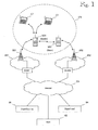
- FIG. 1 is a schematic view of a general network architecture in which the invention can be used.
- Reference documents 1 and 2 (commonly owned patent applications, unpublished at the filing date of the present application, which is why some key sections of their contents are repeated here) discloses a technique in which mobile station MS establishes an ad-hoc WLAN network WN and acts as a gateway for providing a single communication path between one or more a client terminals CT and an internet host HO.
- the communication path extends via an access network AN1 and a data network DN to the host HO.
- a gateway means an interface point between one or more WLAN client terminals on one hand and one or more mobile access networks on the other hand.
- a scalable gateway means a gateway arrangement which is capable of providing a dynamically varying number of simultaneous parallel transfer paths over one or more mobile access networks, such that data packets belonging to the same internet connection between a client terminal and the host are multiplexed (combined) and demultiplexed (divided) at the ends of the simultaneous parallel transfer paths.
- the scalable gateway is established and managed by a master mobile station MS1.
- the scalable gateway established by the master mobile station MS1 may be subsequently joined and supported by zero or more slave mobile stations MS2.
- a slave mobile station MS2 when present, may join the WLAN network WN established by the master mobile station MS1 and support its operation by providing multiple radio interface paths, thus increasing bandwidth. Slave mobile stations MS2 may also detach from the gateway without causing any other harm than a corresponding reduction in bandwidth.
- zero or more slave mobile stations means that the master mobile station MS1 can provide gateway operations by itself, but increased bandwidth may be provided by one or more slave mobile stations MS2.
- the master and slave mobile stations MS1, MS2 can be identical in terms of hardware and software, and any mobile station in which the inventive scalable gateway application is executed first checks if an ad-hoc WLAN network is already established by another mobile station.
- WLAN networks offering the inventive gateway functionality can be detected on the basis of the WLAN SSID identifier. If the mobile station detects an already-established WLAN network, it assumes the role of a slave mobile station. If an already-established ad-hoc WLAN network is not detected, the inventive mobile station establishes the WLAN network itself and assumes the role of the master mobile station for that WLAN network.
- Figure 1 shows only one slave mobile station MS2, but the invention is not restricted to any particular number of mobile stations.
- the invention is ideally implemented such that the master mobile station MS1 and slave mobile station(s) MS2 are coupled to different base stations BS1, BS2, ... Operation via multiple different base stations helps ensure that the cellular radio interfaces between mobile stations and base stations do not constitute bottlenecks. For instance, such coupling to different base stations can be ensured by providing the various mobile stations MS1, MS2 with SIM cards (Subscriber Identity Module) of different access network operators.
- the access networks AN1, AN2 typically comprise gateway GPRS support nodes GGSN1, GGSN2 for connecting to data networks DN, such as the internet.
- implementing the packet routing in the client terminal(s) requires modifications to the protocol stacks in the client terminal(s), which is why the present invention is based on the idea that packet routing via the multiple mobile stations MS1, MS2 is performed in the mobile stations.
- Performing packet routing in the mobile stations provides the benefit that the scalable gateway is almost completely transparent to the client terminal(s), and - as seen from the client terminal(s) - the only change caused by the invention is increased bandwidth.
- FIG. 1 shows a simplified network architecture in the sense that only one specimen of most elements is displayed.
- ad-hoc WLAN networks WN each comprising one master mobile station MS1 and a varying number of slave mobile stations MS2.
- Each ad-hoc WLAN network WN supports a varying number of client terminals CT, each of which may have multiple internet connections to various internet hosts HO. This means that there is a many-to-many mapping among several of the network elements.
- the invention is implemented such that its operation is transparent to the ends of the connections, that is, to the client terminals and the hosts, and any multiplexing and demultiplexing operations (necessitated by the scalability) are performed by the master mobile stations MS1 and multiplexing/demultiplexing computers, which are called ShareMachine computers SM.
- the primary task of the SuperHead computers is to keep track of available ShareMachine computers SM.
- VPN virtual private network
- a VPN is established for each connection section between a mobile station MS1, MS2 and a ShareMachine computer SM.
- the client terminals CT and the internet hosts HO do not need to establish the VPN and, apart from the increased bandwidth, the invention is transparent to them.
- System robustness may be enhanced by implementing the ShareMachine and SuperHead computers SM, SH in a distributed manner, as will be explained in detail in connection with Figure 9 .
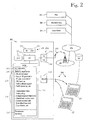
- Figure 2 shows a mobile station configured for use in a scalable WLAN gateway.
- the description of the mobile station begins by describing how a mobile station can act as a unitary (non-scalable) gateway. Such a gateway operation is described in reference documents 1 and 2 (commonly owned, unpublished applications).
- the mobile station MS For acting as a unitary (non-scalable) gateway, the mobile station MS comprises a central processing unit CP 205 and memory 210.
- the mobile station MS comprises or utilizes external input-output circuitry 215 which constitutes the mobile station's user interface and comprises an input circuitry 220 and an output circuitry 225.
- the input circuitry 220 comprises the mobile station's microphone and user-input device, such as a keypad and/or touch screen.
- the output circuitry 225 comprises the mobile station's display and earphone or loudspeaker.
- the mobile station MS further comprises reception/transmission circuitry 230 which comprises a transmission circuitry 235, reception circuitry 240 and antenna 245.
- a subscriber identity module, SIM, 250 is used by an authentication function 260 to authenticate the mobile station user and to identify the user's subscription to the access network.
- the mobile station also comprises WLAN (Wireless Local Area Network) circuitry 255 whose normal mode of usage is acting as a WLAN client to a WLAN base station (not shown).
- WLAN Wireless Local Area Network
- the mobile station's memory MEM 210 may comprise routines for downloading installable program modules and for storing the installable program modules in the memory MEM for execution by the central processing unit CP.
- Figure 1 shows an arrangement in which the mobile station is configured to download installable program modules from a repository RP via a data network DN, an access network AN, the antenna 245 and reception circuitry 240, although other arrangements are equally possible, such as downloading the installable program modules via the data network DN to a client terminal CT, from which the installable program modules are transferred to the mobile station the WLAN circuitry 255 or via some other short-range connection, such as Bluetooth or Universal Serial Bus (USB, not shown separately).
- a repository RP via a data network DN, an access network AN, the antenna 245 and reception circuitry 240
- the access network AN is typically a broadband-capable mobile communication network
- the data network DN is typically the internet or some closed subnetwork implementing internet protocol (IP), commonly called intranets or extranets.
- IP internet protocol
- All previously-discussed elements of Figure 1 can be conventional as used in the relevant art.
- One or more external hosts are accessible via the access network AN and data network DN, as will be described in more detail below.
- reference numeral 280 denotes an area of the memory 210 used to store parameters and variables.
- FIG. 1 describes an applicable mobile station in technical terms.
- Such mobile stations are commercially available: For instance, at the priority date of the present invention, mobile stations based on Symbian S60 or S80 platforms can be used, provided that they support WLAN and broadband communications.
- the mobile station comprises the inventive gateway application 270, either as a factory-installed software application or as a downloadable application.
- the client terminals CT resemble laptop computers or smart telephones, but those skilled in the art will realize that the mobile station MS provided with the inventive gateway application 270 supports virtually any client terminal capable of acting as a WLAN client, personal digital assistants, home entertainment devices, digital cameras, etc., to name just a representative sample of applicable device types.
- reference numeral 272 collectively denotes program-implemented functions which are used to operate the mobile station as a non-scalable gateway which provides one radio interface to one or several client terminals.
- These functions include establishment of an ad-hoc WLAN network, generation of a beacon ID, IP address assignment and discovery (eg DHCP), domain name services (DNS) in cooperation with external domain name servers, multi-protocol support and roaming support.
- the multi-protocol support functionality may include a Network Address & Port Translation (NAPT) block which translates the source and destination addresses. Translation of port numbers may be used to identify various connections to or from the same IP address. A detailed conversion example will be described in connection with Figure 8 .
- NAPT Network Address & Port Translation
- Reference numeral 274 collectively denotes program-implemented functions which are used to operate the mobile station as a scalable gateway which coordinates provision of multiple radio interfaces to one or several client terminals.
- These functions include a multicasting function, which includes packet multicast transmission and signalling in the WLAN network, packet delivery and signalling between a master mobile station and a slave mobile station, and a communication function for communicating with SuperHead and ShareMachine computers.
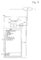
- FIG. 3 shows a block diagram of a multiplexing/demultiplexing computer which, in the context of the present invention, is called a ShareMachine computer SM. It comprises a central processing unit CP 305 and memory 310, as well as a network interface 330 for communicating with data networks DN, such as the internet.
- the ShareMachine computer SM also comprises or utilizes external input-output circuitry 315 which constitutes the ShareMachine computer's user interface and comprises an input circuitry 320 and an output circuitry 325.
- the nature of the user interface depends on which kind of computer is used to implement the ShareMachine computer SM. If the ShareMachine computer is a dedicated computer, it may not need a local user interface, such as a keyboard and display, and the user interface may be a remote interface, wherein the ShareMachine computer is managed remotely, such as from a web browser over the internet, for example. On the other hand, it is expected that some access network operators may display a hostile attitude to the present invention in general and the ShareMachine computers in particular, because the present invention makes it possible to share one or a few access network subscriptions among a larger number of client terminals. Thus some network operators may attempt to block the operation of the ShareMachine computers.
- the user interface should be a local interface, including a display, keyboard and pointing device, although for the purposes of the present invention, the user interface is primarily needed to launch the software application 370 which makes an appropriate computer (hardware-wise) into the inventive ShareMachine computer.
- the user interface may be utilized for obtaining traffic statistics.
- Reference numeral 380 denotes an area of the memory 310 used to store parameters and variables.
- the ShareMachine computer's software application 370 comprises program code for instructing the processor to execute the following functions.
- a signalling function permits the ShareMachine computer to discover participating elements, such as gateway mobile stations.
- a SuperHead communication function enables communication with a SuperHead computer (in XML over HTTPS, for example).
- An optional configuration/reporting function enables configuration of the ShareMachine computer and traffic statistics reporting via a user interface, which may be a local user interface or a remote user interface.
- a packet management function performs packet packing/unpacking and multiplexing/demultiplexing as well as NAT/NAPT (Network Address (and Port) Translation) operations.
- a DNS function permits the ShareMachine computer to participate in DNS operations with pre-existing internet-based DNS servers.
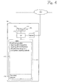
- FIG 4 shows a block diagram of a service coordination server, colloquially called a SuperHead computer and denoted by reference sign SH.
- the purpose of the SuperHead computers is to coordinate the services of the ShareMachine computers SM.
- the SuperHead computer SH can be similar to the ShareMachine computer SM shown in Figure 3 , and the description of the hardware elements will not be repeated.
- a ShareMachine communication function enables communication with ShareMachine computers (in XML over HTTPS, for example).
- a ShareMachine management function enables keeping track of ShareMachine computers and prioritisation of them according to various operating parameters and IP addresses, which are to be communicated to Gateway Mobile Stations.
- An optional configuration/reporting function enables configuration of the SuperHead computer and traffic statistics reporting via a user interface, which may be a local user interface or a remote user interface.
- FIG. 5 is a signalling diagram illustrating a gateway establishment in a scenario which comprises a WLAN client terminal, a mobile station configured as a gateway, a DNS server and an internet host.
- Figure 5 depicts an illustrative scenario involving a client terminal CT and a mobile station which supports a gateway application according to the present invention.
- the inventive gateway application is executed in the mobile station. The execution of the gateway application is typically started in response to a user instruction via the mobile station's user interface.
- the mobile station receives user interface navigation instructions to "Applications" from which the inventive gateway application is selected for execution.
- One of the acts performed by the mobile station's processor, under control of the inventive gateway application is to ensure that the WLAN circuitry of the mobile station is operational.
- the significance of step 5-0, and of the corresponding deactivation step 5-40 is that the mobile station is only reserved for wireless broadband gateway applications for a user-specified time, and at other times the mobile station can perform whatever tasks required by its user.
- step 5-2 the gateway application instructs the mobile station's processor to prepare an ad-hoc WLAN network around the mobile station, by acting as a WLAN base station (as opposed to the mobile station's more conventional usage as a WLAN client).
- step 5-4 the gateway application instructs the mobile station to initiate broadcasting of a beacon ID message, which typically is an IBSSID message as defined in standard IEEE 802.11 x. Step 5-4 is depicted as an arrow, but in practice the broadcasting of the beacon ID message should be repeated until step 5-40 in which the execution of the gateway application is terminated.
- a beacon ID message typically is an IBSSID message as defined in standard IEEE 802.11 x.
- step 5-6 the client terminal CT searches for available WLAN networks and detects the broadcasted beacon ID and selects the WLAN network created by the mobile station MS.
- step 5-8 the client terminal CT, as part of a conventional WLAN attach procedure, requests an IP address from the mobile station's WLAN base station, which returns the requested IP address in step 5-10.
- Dynamic Host Configuration Protocol DHCP is typically used for steps 5-8 and 5-10.
- the client terminal CT tries to retrieve a web page from the internet host (item 190 in Figure 1 ).
- the client terminal CT sends a domain name service (DNS) query for the IP address of the host's web page to the DNS server of the mobile station's gateway application.
- DNS domain name service
- the mobile station's gateway application forwards the DNS query to internet's domain name service and obtains the host's IP address in step 5-16.
- the mobile station's gateway application returns the host's IP address to the client terminal CT.
- step 5-20 the client terminal CT requests a web page from the host's IP address.
- Hypertext Transfer Protocol HTTP is typically used for this purpose. This request, like any communication between the client terminal CT and any internet hosts, takes place via the inventive gateway application being executed in the mobile station.
- Step 5-22 is an optional step which may be omitted in some embodiments.
- step 5-22 comprises redirecting the first HTTP page request from client terminal CT to another internet host, called Host'.
- Host' another internet host
- the gateway application forces the client terminal's first HTTP page request to a forced home page at the IP address of Host'.
- the operator of the site Host' may display advertisements in exchange of sponsoring communication costs over the access network AN.
- the web site Host' returns the requested web page, which the gateway application relays to the client terminal CT in step 5-28.
- step 5-30 the client terminal CT again requests the web page from the host's IP address. Since this the second (or further) page request from the client terminal, the gateway application no longer redirects the HTTP request but relays it to the Host in step 5-32. In steps 5-34 and 5-36 the requested web page from the Host is transmitted to the client terminal. As shown by arrow 50, the process can return from step 5-36 to step 5-20 when future web pages are requested. The loops 5-30 through 5-36 can be repeated until the gateway application is terminated in step 5-40. If the forced home page feature (step 5-22) is not implemented, the first HTTP request (step 5-20) is processed similarly to the subsequent HTTP requests (step 5-30). In subsequent executions of step 5-30, if the HTTP page request relates to a web page for which the gateway application does not have an IP address, a DSN query will be performed (cf. steps 5-14 and 5-16).
- Figure 5 also shows an additional client terminal, denoted CT'. Steps 5-6 through 5-36 will be repeated for each additional client terminal.
- CT' an additional client terminal
- the inventive gateway application which instructs the mobile station MS to act as a WLAN base station (as opposed to a WLAN client)
- the mobile station MS can support an arbitrary number of client terminals which act as WLAN client terminals and which, by virtue of the authentication performed by the mobile station, can share a single subscription to the access network.
- FIG. 5 and the foregoing description of it illustrate use of HTTP protocol.
- the inventive gateway application supports other protocols in an analogous manner and assigns a specific port number to each supported protocol. For instance, the gateway application can instruct the mobile station to convey encrypted HTTPS traffic by utilizing the Proxy Configuration field of HTTPS protocol.
- FIG 6 is a signalling diagram illustrating IP address discovery and DHCP operation, which involves a WLAN client terminal CT, a master mobile station MS1 and a slave mobile station MS2. Both mobile stations MS1 and MS2 execute the inventive gateway application 270 (see Figure 2 ), including the functions 272 and 274. In a typical implementation, the mobile stations MS1 and MS2 and their gateway applications are identical.
- the mobile station that first establishes the ad-hoc WLAN network, as described in connection with Figures 1 and 5 becomes the master mobile station MS1, and any subsequent mobile stations that join the ad-hoc WLAN network afterwards will assume the role of a slave mobile station.
- Figures 6 through 8 only show one slave mobile station MS2, but the invention and its embodiments are scalable to any reasonable number of mobile stations.
- the words “mobile station” may be omitted and the master and slave mobile stations may be referred to as “master” and "slave”.
- step 6-2 the client terminal CT requests an IP address from the master MS1 in an DCHP Discover() procedure.
- step 6-4 the master MS1 sends the client terminal CT the requested IP address.
- the master MS1 whose own IP address of is 192.168.1.1, offers the client terminal the next available IP address, which is 192.168.1.2.
- step 6-6 the mobile station MS2, having detected that an ad-hoc WLAN network already exists, requests an IP address from the master MS1.
- the master MS1 grants in step 6-8 the slave MS2 an IP address of 192.168.2.1, which in this example is derived from the masters' own IP address by setting the third octet to the next available number.
- the slave mobile station MS2 is assigned a subnet of its own.
- This implementation provides certain benefits as regards optimization of resource utilization.
- the slave mobile station MS2 may act as a WLAN gateway to some of the client terminals, whereby it is not necessary to route all traffic via the master mobile station MS1.
- the IP address lease time cannot be very long because the ad-hoc network does not indicate when a slave mobile station leaves the network. After a mobile station leaves the network, the gateway and subnet addresses should be renewed quickly.
- the IP lease time is preferably no more than a few minutes.
- FIG 7 is a signalling diagram illustrating a flow of data packets from a WLAN client terminal CT to an internet host via a master mobile station/gateway MS1, a slave mobile station/gateway MS2 and a ShareMachine computer SM.
- an ad-hoc WLAN network (item WN in Figure 1 ) has been established and a DHCP discovery procedure has been performed, as described in connection with the preceding Figures 5 and 6 .
- the ad-hoc WLAN network comprises a master gateway mobile station MS1 and a slave gateway mobile station MS2, but the client terminal CT only communicates with the master MS1.
- the client terminal CT sends two IP packets IP1 and IP2 to the master MS1.
- the ultimate destination of the IP packets is the internet Host HO.
- the master MS1 thus acts as the client terminal's only access point to the internet.
- the master MS1 sends the first IP packet IP1 as an UDP packet to the ShareMachine computer SM. Any intervening access networks are omitted for clarity, but they are shown in Figure 1 .
- the master MS1 multicasts the second IP packet IP2 as an UDP packet, and the slave MS2 captures the multicast transmission.
- the slave MS2 sends the second IP packet IP2 as an UDP packet to the ShareMachine computer SM.
- the ShareMachine computer SM sends the IP packets IP1 and IP2 to the Host.
- IP1 and IP2 IP2 packets
- UDP packets were used for efficiency's sake. If better robustness is desired and some efficiency can be sacrificed, TCP protocol may be used instead.
- the master gateway mobile station MS1 somehow knows or obtains the address of the ShareMachine computer SM.
- the master MS1 or its user may utilize an internet search engine to discover addresses of available ShareMachine computers.
- An enhanced procedure for obtaining the ShareMachine computer's address from a SuperHead computer will be described in connection with Figure 9 .
- the overhead due to multitasking is reduced by setting a flag in the first (master) mobile station/gateway, such that the slave mobile stations/gateways do not have to unpack each packet to see its destination.
- the multitasking operation also compensates for the fact that packet loss is a definite handicap in mobile access networks. As a result of the multicast transmission via multiple alternative routes, the likelihood of at least one successful packet delivery is increased.
- the multitasking operation increases robustness of the ad-hoc WLAN network. If one of the slave mobile stations/gateways disappears from the WLAN network, the packets may still survive.
- the master MS1 sends the first IP packet IP1 to the ShareMachine computer SM directly, while the second IP packet IP2 is sent via the slave MS2.
- the next IP packet (not shown) will be sent directly again, and so on, in order to achieve load balancing among the gateways MS1, MS2 and the access networks AN1, AN2 (see Figure 1 ).
- the ShareMachine computer SM receives some packets out of sequence, and packet IPn will be received after packet IPn+1.
- the ShareMachine computer SM should be able to buffer packets coming out of sequence until it has received all the packets it needs to forward them to the Host in the correct sequence.
- the ShareMachine computer SM may employ a protocol watchdog timer that raises an alert if some packet is not received for a predetermined period of time, in which case the ShareMachine computer SM may request retransmission of the packets starting from the last properly received packet.
- two internet packets IP3 and IP4 are sent from the Host, via the ShareMachine computer SM and the gateways MS1, MS2, to the client terminal CT.
- the packet transmission from the Host to the client terminal CT is mostly self-explanatory and a detailed description is omitted.
- the slave MS2 must send the packet IP4 over multicast transmission to the master MS1, and it is the task of the master MS1 to assemble the packets in the correct sequence, by requesting retransmission if necessary.
- the embodiment described herein provides the benefit that the operation of the inventive scalable gateway is completely transparent to the client terminal CT and the Host, which need no modifications whatsoever and which can only detect an increased transmission speed.
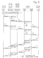
- FIG. 8 is a more detailed signalling diagram illustrating data flow from a WLAN client terminal CT to an internet host HO via a master gateway mobile station MS1, a slave gateway mobile station MS2 and a ShareMachine computer SM.
- the ShareMachine computer comprises a Network Address Translation block, which is also capable of Port Translation, as well as the corresponding reverse translations.
- this block is called a Network Address & Port Translation block NAPT.
- NAPT Network Address & Port Translation block
- the NAPT block may utilize the packets' port numbers to identify the source and destination addresses and to separate the packets based on the addresses.
- the primary IP address assigned to the network elements CT, MS1, MS2, SM and HO are denoted by a suffix "IP" after the reference sign of the respective network element.
- CT IP is the IP address assigned to the client terminal CT.
- the master and slave gateway mobile stations MS1 and MS2 also employ a secondary IP address each, and these are denoted with a prime after the "IP" suffix.
- MS1 IP' is the secondary IP address assigned to the master gateway mobile station MS1.
- the secondary IP addresses of the mobile stations are used for the communication between the mobile stations MS1, MS2 and the ShareMachine computer SM.
- the mobile stations' primary IP addresses MS1 IP and MS2 IP are assigned from the subnetwork of the master mobile station MS1, while the secondary IP addresses MS1 IP' and MS2 IP' are public IP addresses assigned by the mobile stations' respective access network operators.
- Steps 8-11 through 8-17 relate to the transmission of the first uplink packet 1 U from the client terminal CT to the host HO.
- the client terminal CT sends the packet 1 U to the master mobile station MS1.
- the packet 1 U is an Ethernet packet over the WLAN network established by the master mobile station MS1.
- the source and destination addresses of the packet 1 U are the MAC addresses of the master mobile station MS1.
- the packet's payload contains IP Data, as transmitted by the client terminal.
- Table 1 also contains a second row entry for the step 8-11, and this means that there is an IP packet encapsulated within the Ethernet packet.
- the IP packet's source and destination addresses are the IP addresses of the client terminal CT and host HO, respectively.
- Step 8-12 is an optional header packing step, the purpose of which is to optimize the use of the radio interface bandwidth.
- the master mobile station MS1 does not send the first packet 1 U directly to the ShareMachine computer SM but via the slave mobile station MS2.
- step 8-13 comprises sending the packet 1 U as a multicast transmission, which involves sending from the MAC address of MS1 an Ethernet packet into which is encapsulated an UDP packet.
- the UDP packet contains the actual IP packet, as shown in Table 1.
- the slave mobile station MS2 having received the multicast transmission, sends the UDP packet to the IP address of the ShareMachine computer SM in step 8-14.
- the header unpacking step 8-15 reverses the effect of the header packing step 8-12.
- the NAPT block of the ShareMachine computer SM performs Network Address Translation on the packet 1U. After the Network Address Translation, in step 8-17, the ShareMachine computer SM sends the first uplink packet 1 U to the host HO.
- Steps 8-21 through 8-27 relate to the transmission of the second uplink packet 2U from the client terminal CT to the host HO.
- the transmission of the second uplink packet 2U is simpler than the transmission of the first uplink packet 1 U in that the packet 2U is sent directly from the master mobile station MS1 to the ShareMachine computer SM, and the multicast transmission over the WLAN is omitted.
- the transmission of packets originating or terminating at the client terminal CT and host HO is similar regardless of whether or the packet is conveyed via the slave mobile station MS2. This means that the transmission is transparent to the client terminal CT and host HO, which can only detect an improved transmission bandwidth.
- Steps 8-31 through 8-37 relate to the transmission of the first downlink packet ID from the host HO to the client terminal CT.
- steps 8-41 through 8-47 relate to the transmission of the second downlink packet 2D from the host HO to the client terminal CT.
- Table 1 A detailed description of the various transmissions is omitted as the downlink transmission is analogous with the uplink transmission, and the necessary addressing details are indicated in Table 1.
- the mobile stations' public (operator-assigned) IP addresses are used for communicating with the ShareMachine computer SM, while private IP addresses, ie, those assigned by the master mobile station MS1, are used for communicating between the mobile stations.
- Table 1 the mobile stations' public (operator-assigned) IP addresses are used for communicating with the ShareMachine computer SM, while private IP addresses, ie, those assigned by the master mobile station MS1, are used for communicating between the mobile stations.
- the expressions "unique source/destination port” means that the ShareMachine computer SM may identify various connections to the same host HO by means of port numbers. For instance, the ShareMachine computer SM may identify a connection from an exemplary client terminal CT to the host HO by port number 5555, while the next connection will be identified by port number 5556 (or any other unique value). When the host HO sends packets downstream, the ShareMachine computer SM can use the port number to determine which connection the downstream packets belong to.
- Step 9 discloses a procedure that the master mobile station may utilize to discover a serving SuperHead and ShareMachine computers.
- Step 9-2 comprises initialization of the gateway application in the master gateway mobile station MS1, as described in connection with Figures 1 , 2 , 5 and 6 .
- the master MS1 retrieves a list of SuperHead computers from its memory. The installation of the gateway application into the master MS1 may store a default SuperHead list, and this list will be updated on subsequent executions of the gateway application.
- the master MS1 selects the first SuperHead computer address from the list.
- step 9-8 the master MS1 sends an inquiry to the selected SuperHead computer address.
- Step 9-10 involves a test as to whether a response to the inquiry was received from the selected SuperHead computer address. If the test is successful, the process proceeds to step 9-12, in which the master MS1 begins to use one or more of the obtained ShareMachine addresses. In step 9-14 the master MS1 stores the list of SuperHead addresses.
- step 9-10 determines whether the test in step 9-10 fails. If the test in step 9-10 fails, the process proceeds to steps 9-16 and 9-18, in which the next SuperHead address from the list is tried. If the list of SuperHead addresses is exhausted, the process proceeds to step 9-20 and 9-22, which involve various user alerting steps and/or error recovery procedures. For instance, the master mobile station MS1 or its user may employ an internet search engine to obtain more SuperHead addresses.
- a proper response from the SuperHead computer to the master MS1 should include a list of IP addresses of one or more available ShareMachine computers and, preferably, an updated list of available SuperHead computers.
- such lists are sent in XML (extendible Markup Language) format. Reception of the list of available ShareMachine computers permits the master MS1 to know computers have reported themselves to the SuperHead computer as potential ShareMachine computers.
- each connection is served by one ShareMachine computer, but one master MS1 may serve several connections from one or more client terminals, and each connection may be served by a different ShareMachine computer. Also, it is beneficial if the master MS1 obtains and stores a list of several ShareMachine addresses, in case the active ShareMachine computer detaches itself from service or otherwise ceases to serve the connection.
- the SuperHead and ShareMachine computers are implemented in a distributed manner.
- Such distributed implementation proves certain advantages, in addition to capacity considerations. For instance, many internet services or servers are threatened by network vandalism or sabotage, such as denial-of-service attacks.
- the inventive distribution of the access network subscriptions among several client terminals may result in access network traffic which is heavier than average, and the network operators may be tempted to prevent or obstruct the operation of the inventive gateway applications in the mobile stations.
- a distributed implementation of the SuperHead and ShareMachine computers makes them less vulnerable to such network-based vandalism by hackers or obstructions by access network operators. Robustness may be further improved by utilizing dynamic IP addresses for the SuperHead and/or ShareMachine computers.
- the lists of SuperHead and ShareMachine computers are updated regularly, via inquiries to a SuperHead computer.
- Frequent updating of the SuperHead and ShareMachine addresses provide further robustness, particularly in cases wherein the SuperHead and/or ShareMachine computers are conventional home computers whose spare time is being utilized to serve connection in the manner described herein. When such home computers are turned off or used for other purposes, they stop operating as SuperHead and/or ShareMachine computers. Accordingly, the address updating frequency should be dimensioned based on representative operating patterns of typical home computers, with 10 minutes being a good starting value.
- the functions of the SuperHead and ShareMachine computers are combined in such a manner that the ShareMachine computers keep track of one another.
- the ShareMachine computers also act as SuperHead computers.
- the previously described embodiments relate to provision of a scalable gateway functionality.
- One of the key elements of the invention is establishment of a WLAN base station in a mobile station. By establishing a WLAN base station in the mobile station, it will be possible to utilize some of the enhanced functionality of modern mobile stations.
- the inventive gateway application can, in some specific embodiments, provide additional or supplementary services which utilize some of the functionality of modern mobile stations.
- supplementary services are provided by an arrangement in which a supplementary server enhances the service(s) provided by a primary server.
- a supplementary server can be part of the functionality of the inventive WLAN gateway application, or it can be implemented as a network element distinct from the primary server.
- the inventive gateway application may be enhanced to associate GPS-provided geographical coordinates to the traffic originated by the client terminal, or to some of that traffic. For instance, the gateway application can tag still or video image data with geographical coordinates and/or use some additional service (not shown separately) that maps the with geographical coordinates to a plaintext name of the relevant location.
- the gateway application associates GPS-provided coordinates to the traffic, or some of it, while the actual tagging of the images with the coordinates is provided by some additional server, such as an image sharing server (not shown separately).
- some additional server such as an image sharing server (not shown separately).
- the gateway application can provide additional services on the basis of the geographical coordinates. For instance, the gateway application can recognize various queries initiated by the client terminal and/or responses to those queries by internet servers and enhance the query responses by relevant map or photography information. For instance, the gateway application can detect a query to "post" and provide the query response with a map and/or photograph of the post office closest to the mobile station's GPS-provided geographical coordinates. In order to obtain the map and/or photograph, the gateway application may query a supplementary server which provides the requested functionality.
- Such additional services relates to traffic statistics which the gateway application collects and transmits to some internet-based supplementary server (not shown separately).
- a supplementary server may use the traffic statistics to monitor Quality of Service (QoS) parameters, which can be used to maintain the QoS at a specified level and/or to optimize resource usage in the access network.
- QoS Quality of Service
- the supplementary server is an advertising server.
- the advertising server may utilize the traffic statistics for targeted or tailored advertising to the client terminal CT.
- traffic statistics may include, for example, user identification, usage (amount of traffic, usage times, internet addresses visited, query parameters, or the like).
- the gateway application can transmit traffic statistics to a billing server which participates in charging the client terminal's subscriber.
- the advertising server and the billing server may cooperate in such a manner that the advertising server's operator sells advertisement space or time and the advertising server credits the client terminal's subscriber for any advertisements received. The credits are then relayed to and used by the billing server in order to reduce the client terminal's subscriber's invoice, generate additional services, extend pre-paid subscription time, to name just a few examples.
- the gateway application may be configured to convey the mobile station's location, or some derivative it, to the advertising server for targeted or tailored advertising on the basis of the mobile station's location.
- targeted advertising for some goods or service may include sending an advertisement to a client terminal only if the mobile station's location indicates that the client terminal is reasonably close to the outlet of the goods or service.
- tailored advertising may be implemented such that the advertisement indicates the address or location of the closest outlet.
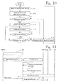
- FIGs 10 and 11 illustrate some exemplary embodiments in which the present invention benefits from the functionality of modern mobile stations, such that the resulting WLAN gateway is functionally superior to dedicated WLAN base stations.
- Figure 10 shows an embodiment in which the WLAN circuitry, and optionally the WLAN gateway application, in the mobile station MS is activated periodically to detect possible WLAN client terminals CT nearby.
- a WLAN-capable digital camera acts as a WLAN client terminal.
- the mobile station MS employs two timers which may be realized by means of software-implemented tick counters, as is well known to those skilled in the art. One of the timers is called a sleep timer while the other is called a watchdog timer.
- the sleep timer's function is to periodically wake up the mobile station's WLAN circuitry, and optionally the WLAN gateway application.
- the watchdog timer is used to detect non-activity periods of predetermined length in the WLAN network so that the WLAN circuitry can be powered off in order to optimise battery resources.
- step 10-1 the WLAN circuitry of the mobile station MS is powered off and the execution of the WLAN gateway application may be suspended or terminated.
- Step 10-1 terminates when the sleep timer expires. For instance, the sleep timer may generate a processor interrupt which directs the mobile station's processor to perform program routines for activating the WLAN circuitry and starting or resuming execution of the WLAN gateway application.
- step 10-2 the mobile station has established a WLAN network.
- step 10-3 the mobile station checks if any client terminal(s), such as the exemplary digital camera, attempt(s) to attach to the WLAN network. If not, the process proceeds to step 10-8, in which the WLAN network and circuitry are deactivated and the process begins anew at step 10-1.
- Step 10-6 includes a test to detect client terminal activity. If client terminal activity is detected, the process returns to step 10-4 in which the watchdog timer is restarted. Naturally, any client-related requests are served as well, as part of the basic functionality of the WLAN gateway application.
- step 10-7 is a test as to whether the watchdog timer has expired. If not, the process returns to step 10-5 in which the WLAN network is maintained without restarting the watchdog timer. Eventually, a moment occurs when no client activity has been detected and the watchdog timer expires, and this is detected in step 10-7. Then, in step 10-8, the WLAN network and circuitry are deactivated and the process begins anew at step 10-1.
- the WLAN gateway application may terminate its own execution and power off the mobile station's WLAN circuitry.
- the automatic execution of the gateway application and the accompanying automatic activation of the mobile station's WLAN circuitry provides certain benefits. For instance, both digital cameras and mobile stations are handicapped by small user interfaces and relatively short battery life, particularly when their liquid-crystal displays (LCD) are illuminated.
- LCD liquid-crystal displays
- FIG 11 shows an embodiment in which the mobile station's location-determination functionality is used to enhance image uploading to an image hosting server.
- a WLAN connection is established between the gateway application being executed in the mobile station MS and the WLAN-equipped digital camera CAM acting as a client terminal CT.
- the camera CAM/CT initiates a DNS inquiry to obtain the internet address of the image hosting server.
- an embodiment of the gateway application being executed in the mobile station MS detects that the camera/client terminal CAM/CT executes a location-aware application. Accordingly, the gateway application uses the mobile station's location-determination functionality to determine the mobile station's location.
- the mobile station's location may be determined on the basis of the mobile station's built-in satellite-positioning device (GPS) or on the basis of cell ID determination in the access networks.
- the gateway application sends the mobile station's location to an embodiment of the supplementary server SS, which in this scenario receives the mobile station's location and returns a plaintext-formatted location description.
- the geographical coordinates or cell ID of Piccadilly Circus might be converted to a plaintext description of "Piccadilly Circus, London”.
- the camera/client terminal CAM/CT begins uploading of image data to the image hosting server.
- the gateway application complements the image data with the mobile station's location.
- the location data is placed in a metadata field of the image(s).
Landscapes
- Engineering & Computer Science (AREA)
- Computer Networks & Wireless Communication (AREA)
- Signal Processing (AREA)
- Computer Security & Cryptography (AREA)
- Mobile Radio Communication Systems (AREA)
- Telephonic Communication Services (AREA)
- Data Exchanges In Wide-Area Networks (AREA)
Claims (6)
- Mobilstation (MS1), die Folgendes aufweist:- einen Speicher (MEM, 210) zum Speichern von Anwendungen und Daten;- einen Prozessor (205) zum Ausführen der gespeicherten Anwendungen;- eine Benutzerschnittstelle (215), die einen Eingabeabschnitt (220) und einen Ausgabeabschnitt (225) aufweist;- Empfangs-/Sendeschaltkreise (230) zum Bereitstellen einer Kommunikationsschnittstelle zu einem oder mehreren Zugangsnetzen (AN);- ein Authentifizierungsmittel (260), das dafür ausgelegt ist, einen Benutzer der Mobilstation zu authentifizieren;- einen Funktransceiver (230), der eingerichtet ist, als Reaktion auf eine erfolgreiche Authentifizierung des Benutzers der Mobilstation, eine Breitbandverbindung mit einem Mobilkommunikationsnetzwerk aufzubauen und aufrechtzuerhalten;- ein drahtloses lokales Netzwerk-Mittel, WLAN-Mittel, (255), das auf einen Aktivierungs- oder Deaktivierungsbefehl reagiert, gemäß einer Einstellung, die über den Eingabeabschnitt (220) der Benutzerschnittstelle (215) empfangen wird; dadurch gekennzeichnet, dass- der Speicher (MEM, 210) eine Gateway-Anwendung (270) aufweist, die aufweist:- einen ersten Codeabschnitt, um dem Prozessor zu befehlen, das WLAN-Mittel zu aktivieren (5-0), um festzustellen, ob ein WLAN-Netzwerk (WN) vorhanden ist, und wenn kein WLAN-Netzwerk vorhanden ist, als eine WLAN-Basisstation zu die-nen, die imstande ist, mit mindestens einem WLAN-Client-Endgerät (CT) und mindestens einer Slave-Mobilstation (MS2) über ein durch die Mobilstation (MS1), die zu einer Master-Mobilstation wird, hergestelltes ad-hoc-WLAN-Netzwerk (WN) zu kommunizieren;- einen zweiten Codeabschnitt, um dem Prozessor zu befehlen, eine Netzwerkkennung (5-2, 5-4) für die WLAN-Basisstation zu erzeugen;- einen dritten Codeabschnitt, um dem Prozessor zu befehlen, eine Internetproto-kolladresse für das mindestens eine WLAN-Client-Endgerät und für die mindestens eine Slave-Mobilstation (MS2) zuzuweisen (5-8, 5-10; 6-2 ... 6-8);- einen vierten Codeabschnitt, um dem Prozessor zu befehlen, Domänennamen-Dienst-Anfragen, DNS-Anfragen, (5-12 ... 5-18) in Zusammenarbeit mit einem externen DNS-System aufzulösen;- einen fünften Codeabschnitt, um dem Prozessor zu befehlen, mindestens eine Port-Nummer für jedes Protokoll zuzuweisen, das durch die Gateway-Anwendung unterstützt wird;- einen sechsten Codeabschnitt, um dem Prozessor zu befehlen, Internet-Traffic (5-30 ... 5-36) zwischen dem mindestens einen WLAN-Client-Endgerät und einem Internet-Host (HO) über die Breitbandverbindung zu tunneln;- wobei das Tunneln des Internet-Traffics das Aufbauen und Verwalten von mehreren gleichzeitigen Übertragungswegen (7-6, 7-8; 7-18, 7-22; 8-13, 8-23; 8-34, 8-44) zwischen der Mobilstation (MS1) und dem Internet-Host (HO) aufweist, wobei die mehreren gleichzeitigen Übertragungswege einen ersten Übertragungsweg über die Empfangs-/Sendeschaltkreise (210) der Mobilstation (MS1) und mindestens einen zweiten Übertragungsweg über die Empfangs-/Sendeschaltkreise der Slave-Mobilstation (MS2) aufweisen.
- Mobilstation (MS1) nach Anspruch 1, die ferner Mittel zur Nutzung einer Multicast-Übertragung auf dem mindestens einen zweiten Übertragungsweg aufweist.
- Mobilstation (MS1) nach Anspruch 1 oder 2, die ferner Mittel zum Aufbauen und Verwalten der mehreren gleichzeitigen Übertragungswege aufweist, so dass die mehreren gleichzeitigen Übertragungswege von der Mobilstation und von einem Multi-plex-/Demultiplexcomputer (SM), der ein anderer Computer als der Internet-Host (HO) ist, ausgehen und an ihnen enden.
- Mobilstation (MS1) nach Anspruch 3, die ferner Signalisierungsmittel zum Kommunizieren mit mehreren Dienstkoordinationsservern (SH) aufweist, die den Betrieb von mehreren Multiplex-/Demultiplexcomputern (SM) koordinieren; wobei das Signalisierungsmittel Codeabschnitte aufweist, um dem Prozessor zu befehlen:- aus dem Speicher eine Liste abzurufen, die einige der mehreren Dienstkoordinationsserver (SH) angibt;- eine Anfrage an einen oder mehrere der mehreren Dienstkoordinationsserver (SH) zu senden, bis eine Antwort empfangen wird, wobei die Antwort eine aktualisierte Liste von Dienstkoordinationsservern angibt;- eine Adresse von einem oder mehreren aktiven Multiplex-/Demultiplex-computern (SM) von mindestens einem der mehreren Dienstkoordinationsserver (SH) zu beschaffen;- die aktualisierte Liste der Dienstkoordinationsserver im Speicher zu speichern.
- Softwareträger für eine Mobilstation, die aufweist: einen Speicher (MEM, 210) zum Speichern von Anwendungen und Daten; einen Prozessor (205) zum Ausführen der gespeicherten Anwendungen; eine Benutzerschnittstelle (215), die einen Eingabeabschnitt (220) und einen Ausgabeabschnitt (225) aufweist; Empfangs-/Sendeschaltkreise (230) zum Bereitstellen einer Kommunikationsschnittstelle zu einem oder mehreren Zugangsnetzen (AN); ein Authentifizierungsmittel (260), betreibbar zum Authentifizieren eines Benutzers der Mobilstation; einen Funktransceiver (230), der betriebsfähig ist, als Reaktion auf eine erfolgreiche Authentifizierung des Benutzers der Mobilstation, eine Breitbandverbindung mit einem Mobilkommunikationsnetzwerk aufzubauen und aufrechtzuerhalten; und ein drahtloses lokales Netzwerk-Mittel, WLAN-Mittel, (255), das auf einen Aktivierungs- oder Deak-tivierungsbefehl reagiert, gemäß einer Einstellung, die über den Eingabeabschnitt (220) der Benutzerschnittstelle (215) empfangen wird;
dadurch gekennzeichnet, dass
der Softwareträger eine Gateway-Anwendung (270) aufweist, die aufweist:- einen ersten Codeabschnitt, um dem Prozessor zu befehlen, das WLAN-Mittel zu aktivieren (5-0), um festzustellen, ob ein WLAN-Netzwerk (WN) vorhanden ist, und wenn kein WLAN-Netzwerk vorhanden ist, als eine WLAN-Basisstation zu dienen, die imstande ist, mit mindestens einem WLAN-Client-Endgerät (CT) und mindestens einer Slave-Mobilstation (MS2) über ein durch die Mobilstation (MS1), die zu einer Master-Mobilstation wird, hergestelltes ad-hoc-WLAN-Netzwerk (WN) zu kommunizieren;- einen zweiten Codeabschnitt, um dem Prozessor zu befehlen, eine Netzwerkkennung (5-2, 5-4) für die WLAN-Basisstation zu erzeugen;- einen dritten Codeabschnitt, um dem Prozessor zu befehlen, eine Internetprotokolladresse für das mindestens eine WLAN-Client-Endgerät und für die mindestens eine Slave-Mobilstation (MS2) zuzuweisen (5-8, 5-10; 6-2 ... 6-8);- einen vierten Codeabschnitt, um dem Prozessor zu befehlen, Domänennamen-Dienst-Anfragen, DNS-Anfragen, (5-12 ... 5-18) in Zusammenarbeit mit einem externen DNS-System aufzulösen;- einen fünften Codeabschnitt, um dem Prozessor zu befehlen, mindestens eine Port-Nummer für jedes Protokoll zuzuweisen, das durch die Gateway-Anwendung unterstützt wird;- einen sechsten Codeabschnitt, um dem Prozessor zu befehlen, Internet-Traffic (5-30 ... 5-36) zwischen dem mindestens einen WLAN-Client-Endgerät und einem Internet-Host (HO) über die Breitbandverbindung zu tunneln;- wobei das Tunneln des Internet-Traffics das Aufbauen und Verwalten von mehreren gleichzeitigen Übertragungswegen (7-6, 7-8; 7-18, 7-22; 8-13, 8-23; 8-34, 8-44) zwischen der Mobilstation (MS1) und dem Internet-Host (HO) aufweist, wobei die mehreren gleichzeitigen Übertragungswege einen ersten Übertragungsweg über die Empfangs-/Sendeschaltkreise (210) der Mobilstation (MS1) und mindestens einen zweiten Übertragungsweg über die Empfangs-/Sendeschaltkreise der Slave-Mobilstation (MS2) aufweisen. - Verfahren zum Betreiben einer Mobilstation; wobei die Mobilstation aufweist: einen Speicher (MEM, 210) zum Speichern von Anwendungen und Daten; einen Prozessor (205) zum Ausführen der gespeicherten Anwendungen; eine Benutzerschnittstelle (215), die einen Eingabeabschnitt (220) und einen Ausgabeabschnitt (225) aufweist; Empfangs-/Sendeschaltkreise (230) zum Bereitstellen einer Kommunikationsschnittstelle zu einem oder mehreren Zugangsnetzen (AN); ein Authentifizierungsmittel (260), betreibbar zum Authentifizieren eines Benutzers der Mobilstation; einen Funktransceiver (230), der betriebsfähig ist, als Reaktion auf eine erfolgreiche Authentifizierung des Benutzers der Mobilstation, eine Breitbandverbindung mit einem Mobilkommunikationsnetzwerk aufzubauen und aufrechtzuerhalten; und ein drahtloses lokales Netzwerk-Mittel, WLAN-Mittel, (255), das auf einen Aktivierungs- oder Deaktivierungsbefehl reagiert, gemäß einer Einstellung, die über den Eingabeabschnitt (220) der Benutzerschnittstelle (215) empfangen wird;
dadurch gekennzeichnet, dass das Verfahren umfasst, den Prozessor (205) durch eine Gateway-Anwendung (270) anzuweisen, die folgenden Operationen zu steuern:- Aktivieren (5-0) des WLAN-Mittels, um festzustellen, ob ein WLAN-Netzwerk (WN) vorhanden ist, und wenn kein WLAN-Netzwerk vorhanden ist, als eine WLAN-Basisstation zu dienen, die imstande ist, mit mindestens einem WLAN-Client-Endgerät (CT) und mindestens einer Slave-Mobilstation (MS2) über ein durch die Mobilstation (MS1), die zu einer Master-Mobilstation wird, hergestelltes ad-hoc-WLAN-Netzwerk (WN) zu kommunizieren;- Erzeugen einer Netzwerkkennung (5-2, 5-4) für die WLAN-Basisstation;- Zuweisen (5-8, 5-10; 6-2 ... 6-8) einer Internetprotokolladresse für das mindestens eine WLAN-Client-Endgerät und für die mindestens eine Slave-Mobilstation (MS2);- Auflösen von Domänennamen-Dienst-Anfragen, DNS-Anfragen, (5-12 ... 5-18) in Zusammenarbeit mit einem externen DNS-System;- Zuweisen mindestens einer Port-Nummer für jedes Protokoll, das durch die Gateway-Anwendung unterstützt wird;- Tunneln von Internet-Traffic (5-30 ... 5-36) zwischen dem mindestens einen WLAN-Client-Endgerät und einem Internet-Host (HO) über die Breitbandverbindung;- wobei das Tunneln des Internet-Traffics das Aufbauen und Verwalten von mehreren gleichzeitigen Übertragungswegen (7-6, 7-8; 7-18, 7-22; 8-13, 8-23; 8-34, 8-44) zwischen der Mobilstation (MS1) und dem Internet-Host (HO) aufweist, wobei die mehreren gleichzeitigen Übertragungswege einen ersten Übertragungsweg über die Empfangs-/Sendeschaltkreise (210) der Mobilstation (MS1) und mindestens einen zweiten Übertragungsweg über die Empfangs-/Sendeschaltkreise der Slave-Mobilstation (MS2) aufweisen.
Applications Claiming Priority (2)
| Application Number | Priority Date | Filing Date | Title |
|---|---|---|---|
| FI20080345A FI20080345A0 (fi) | 2008-05-09 | 2008-05-09 | Symbian S60 puhelin 3G kaistanyhdistäjänä |
| PCT/FI2008/050717 WO2009135986A1 (en) | 2008-05-09 | 2008-12-09 | Scalable wlan gateway |
Publications (3)
| Publication Number | Publication Date |
|---|---|
| EP2274875A1 EP2274875A1 (de) | 2011-01-19 |
| EP2274875A4 EP2274875A4 (de) | 2013-03-20 |
| EP2274875B1 true EP2274875B1 (de) | 2015-02-11 |
Family
ID=39523013
Family Applications (1)
| Application Number | Title | Priority Date | Filing Date |
|---|---|---|---|
| EP08874187.1A Active EP2274875B1 (de) | 2008-05-09 | 2008-12-09 | Skalierbares wlan-gateway |
Country Status (10)
| Country | Link |
|---|---|
| US (7) | US8064418B2 (de) |
| EP (1) | EP2274875B1 (de) |
| JP (2) | JP5255115B2 (de) |
| KR (1) | KR101239450B1 (de) |
| CN (1) | CN102017528B (de) |
| AU (1) | AU2008356135B2 (de) |
| BR (1) | BRPI0822670B1 (de) |
| ES (1) | ES2536939T3 (de) |
| FI (1) | FI20080345A0 (de) |
| WO (1) | WO2009135986A1 (de) |
Families Citing this family (84)
| Publication number | Priority date | Publication date | Assignee | Title |
|---|---|---|---|---|
| FI20080032A0 (fi) | 2008-01-16 | 2008-01-16 | Joikusoft Oy Ltd | Älypuhelin WLAN-tukiasemana |
| FI20080345A0 (fi) | 2008-05-09 | 2008-05-09 | Joikusoft Oy Ltd | Symbian S60 puhelin 3G kaistanyhdistäjänä |
| US8626115B2 (en) | 2009-01-28 | 2014-01-07 | Headwater Partners I Llc | Wireless network service interfaces |
| US8250207B2 (en) | 2009-01-28 | 2012-08-21 | Headwater Partners I, Llc | Network based ambient services |
| US8635335B2 (en) | 2009-01-28 | 2014-01-21 | Headwater Partners I Llc | System and method for wireless network offloading |
| US8346225B2 (en) | 2009-01-28 | 2013-01-01 | Headwater Partners I, Llc | Quality of service for device assisted services |
| US8402111B2 (en) | 2009-01-28 | 2013-03-19 | Headwater Partners I, Llc | Device assisted services install |
| US8391834B2 (en) | 2009-01-28 | 2013-03-05 | Headwater Partners I Llc | Security techniques for device assisted services |
| US8275830B2 (en) | 2009-01-28 | 2012-09-25 | Headwater Partners I Llc | Device assisted CDR creation, aggregation, mediation and billing |
| US8589541B2 (en) | 2009-01-28 | 2013-11-19 | Headwater Partners I Llc | Device-assisted services for protecting network capacity |
| US8340634B2 (en) | 2009-01-28 | 2012-12-25 | Headwater Partners I, Llc | Enhanced roaming services and converged carrier networks with device assisted services and a proxy |
| US8832777B2 (en) | 2009-03-02 | 2014-09-09 | Headwater Partners I Llc | Adapting network policies based on device service processor configuration |
| US8406748B2 (en) | 2009-01-28 | 2013-03-26 | Headwater Partners I Llc | Adaptive ambient services |
| US8548428B2 (en) | 2009-01-28 | 2013-10-01 | Headwater Partners I Llc | Device group partitions and settlement platform |
| US9980146B2 (en) | 2009-01-28 | 2018-05-22 | Headwater Research Llc | Communications device with secure data path processing agents |
| US9571559B2 (en) | 2009-01-28 | 2017-02-14 | Headwater Partners I Llc | Enhanced curfew and protection associated with a device group |
| US9755842B2 (en) | 2009-01-28 | 2017-09-05 | Headwater Research Llc | Managing service user discovery and service launch object placement on a device |
| US8745191B2 (en) | 2009-01-28 | 2014-06-03 | Headwater Partners I Llc | System and method for providing user notifications |
| US12388810B2 (en) | 2009-01-28 | 2025-08-12 | Headwater Research Llc | End user device that secures an association of application to service policy with an application certificate check |
| US10237757B2 (en) | 2009-01-28 | 2019-03-19 | Headwater Research Llc | System and method for wireless network offloading |
| US10779177B2 (en) | 2009-01-28 | 2020-09-15 | Headwater Research Llc | Device group partitions and settlement platform |
| US9706061B2 (en) | 2009-01-28 | 2017-07-11 | Headwater Partners I Llc | Service design center for device assisted services |
| US9565707B2 (en) | 2009-01-28 | 2017-02-07 | Headwater Partners I Llc | Wireless end-user device with wireless data attribution to multiple personas |
| US10783581B2 (en) | 2009-01-28 | 2020-09-22 | Headwater Research Llc | Wireless end-user device providing ambient or sponsored services |
| US9578182B2 (en) | 2009-01-28 | 2017-02-21 | Headwater Partners I Llc | Mobile device and service management |
| US12389218B2 (en) | 2009-01-28 | 2025-08-12 | Headwater Research Llc | Service selection set publishing to device agent with on-device service selection |
| US10057775B2 (en) | 2009-01-28 | 2018-08-21 | Headwater Research Llc | Virtualized policy and charging system |
| US12432130B2 (en) | 2009-01-28 | 2025-09-30 | Headwater Research Llc | Flow tagging for service policy implementation |
| US10326800B2 (en) | 2009-01-28 | 2019-06-18 | Headwater Research Llc | Wireless network service interfaces |
| US10200541B2 (en) | 2009-01-28 | 2019-02-05 | Headwater Research Llc | Wireless end-user device with divided user space/kernel space traffic policy system |
| US10248996B2 (en) | 2009-01-28 | 2019-04-02 | Headwater Research Llc | Method for operating a wireless end-user device mobile payment agent |
| US10484858B2 (en) | 2009-01-28 | 2019-11-19 | Headwater Research Llc | Enhanced roaming services and converged carrier networks with device assisted services and a proxy |
| US9351193B2 (en) | 2009-01-28 | 2016-05-24 | Headwater Partners I Llc | Intermediate networking devices |
| US9609510B2 (en) | 2009-01-28 | 2017-03-28 | Headwater Research Llc | Automated credential porting for mobile devices |
| US9253663B2 (en) | 2009-01-28 | 2016-02-02 | Headwater Partners I Llc | Controlling mobile device communications on a roaming network based on device state |
| US9557889B2 (en) | 2009-01-28 | 2017-01-31 | Headwater Partners I Llc | Service plan design, user interfaces, application programming interfaces, and device management |
| US9954975B2 (en) | 2009-01-28 | 2018-04-24 | Headwater Research Llc | Enhanced curfew and protection associated with a device group |
| US11218854B2 (en) | 2009-01-28 | 2022-01-04 | Headwater Research Llc | Service plan design, user interfaces, application programming interfaces, and device management |
| US10264138B2 (en) | 2009-01-28 | 2019-04-16 | Headwater Research Llc | Mobile device and service management |
| US12166596B2 (en) | 2009-01-28 | 2024-12-10 | Disney Enterprises, Inc. | Device-assisted services for protecting network capacity |
| US10064055B2 (en) | 2009-01-28 | 2018-08-28 | Headwater Research Llc | Security, fraud detection, and fraud mitigation in device-assisted services systems |
| US9392462B2 (en) | 2009-01-28 | 2016-07-12 | Headwater Partners I Llc | Mobile end-user device with agent limiting wireless data communication for specified background applications based on a stored policy |
| US9572019B2 (en) | 2009-01-28 | 2017-02-14 | Headwater Partners LLC | Service selection set published to device agent with on-device service selection |
| US11985155B2 (en) | 2009-01-28 | 2024-05-14 | Headwater Research Llc | Communications device with secure data path processing agents |
| US12452377B2 (en) | 2009-01-28 | 2025-10-21 | Headwater Research Llc | Service design center for device assisted services |
| US11973804B2 (en) | 2009-01-28 | 2024-04-30 | Headwater Research Llc | Network service plan design |
| US10798252B2 (en) | 2009-01-28 | 2020-10-06 | Headwater Research Llc | System and method for providing user notifications |
| US9270559B2 (en) | 2009-01-28 | 2016-02-23 | Headwater Partners I Llc | Service policy implementation for an end-user device having a control application or a proxy agent for routing an application traffic flow |
| US9955332B2 (en) | 2009-01-28 | 2018-04-24 | Headwater Research Llc | Method for child wireless device activation to subscriber account of a master wireless device |
| US8793758B2 (en) | 2009-01-28 | 2014-07-29 | Headwater Partners I Llc | Security, fraud detection, and fraud mitigation in device-assisted services systems |
| US10715342B2 (en) | 2009-01-28 | 2020-07-14 | Headwater Research Llc | Managing service user discovery and service launch object placement on a device |
| US10841839B2 (en) | 2009-01-28 | 2020-11-17 | Headwater Research Llc | Security, fraud detection, and fraud mitigation in device-assisted services systems |
| US9647918B2 (en) | 2009-01-28 | 2017-05-09 | Headwater Research Llc | Mobile device and method attributing media services network usage to requesting application |
| US10492102B2 (en) | 2009-01-28 | 2019-11-26 | Headwater Research Llc | Intermediate networking devices |
| US12543031B2 (en) | 2009-01-28 | 2026-02-03 | Headwater Research Llc | Adapting network policies based on device service processor configuration |
| US9858559B2 (en) | 2009-01-28 | 2018-01-02 | Headwater Research Llc | Network service plan design |
| KR101015665B1 (ko) * | 2009-03-16 | 2011-02-22 | 삼성전자주식회사 | 이동 통신 단말과 액세스 포인트 간에 연결 방법 및 시스템 |
| CN102106118B (zh) * | 2009-09-28 | 2015-04-15 | 华为技术有限公司 | 可扩展的无线局域网网关 |
| US8279776B1 (en) * | 2009-10-26 | 2012-10-02 | Sprint Communications Company L.P. | Network address translation based on a reverse domain name service |
| EP2505009B1 (de) * | 2009-11-23 | 2017-08-16 | Alcatel Lucent | Kooperative kommunikation in mobilfunknetzen |
| US8570993B2 (en) * | 2010-05-20 | 2013-10-29 | At&T Mobility Ii Llc | Wi-Fi intelligent selection engine |
| US8238941B2 (en) * | 2010-07-08 | 2012-08-07 | Global Business Software Development Technologies, Inc. | System and method for determining a location for a mobile device |
| SE537688C2 (sv) * | 2010-07-26 | 2015-09-29 | Connectblue Ab | Metod och anordning för roaming i ett lokalt kommunikationssystem |
| CN102404416B (zh) | 2010-09-16 | 2016-06-15 | 中兴通讯股份有限公司 | 一种获取dns的方法和隧道网关设备 |
| KR101780021B1 (ko) * | 2010-10-18 | 2017-10-11 | 삼성전자주식회사 | 네트워크 인터페이스의 자동 설정에 기초해 인터넷 연결을 공유하는 방법 및 장치 |
| US8671221B2 (en) * | 2010-11-17 | 2014-03-11 | Hola Networks Ltd. | Method and system for increasing speed of domain name system resolution within a computing device |
| JP5803112B2 (ja) * | 2011-01-14 | 2015-11-04 | ソニー株式会社 | 無線端末装置、情報処理装置、通信システムおよび無線端末装置の制御方法 |
| US9154826B2 (en) | 2011-04-06 | 2015-10-06 | Headwater Partners Ii Llc | Distributing content and service launch objects to mobile devices |
| US9059802B2 (en) | 2011-11-09 | 2015-06-16 | At&T Mobility Ii Llc | Received signal strength indicator snapshot analysis |
| CN102438331B (zh) * | 2012-01-12 | 2016-04-13 | 惠州Tcl移动通信有限公司 | 一种移动终端通过手机上网的方法及系统 |
| US20130238782A1 (en) * | 2012-03-09 | 2013-09-12 | Alcatel-Lucent Usa Inc. | Method and apparatus for identifying an application associated with an ip flow using dns data |
| US20140173111A1 (en) * | 2012-12-19 | 2014-06-19 | Netzero Wireless, Inc. | Data usage management systems and methods |
| US9955361B2 (en) * | 2013-02-26 | 2018-04-24 | Dali Systems Co., Ltd. | Method and system for WI-FI data transmission |
| KR20140117995A (ko) * | 2013-03-27 | 2014-10-08 | 한국전자통신연구원 | 다중 사용자 영상 전송 장치 및 방법 |
| AU2013399900B2 (en) * | 2013-09-09 | 2017-05-04 | Telefonaktiebolaget L M Ericsson (Publ) | Connecting radio base stations via a third party network |
| KR101777305B1 (ko) * | 2013-11-18 | 2017-09-11 | 주하이 킹소프트 온라인 게임 테크놀로지 컴퍼니 리미티드 | 파일공유방법, 장치 및 모바일 장비 |
| EP3349420B1 (de) * | 2015-09-29 | 2022-02-23 | Huawei Technologies Co., Ltd. | Ip-adresszuteilungsverfahren, -vorrichtung und -system für ein master-slave-netzwerk |
| US9473987B1 (en) * | 2015-11-12 | 2016-10-18 | International Business Machines Corporation | Combining bandwidth from multiple cellular connections into a single WLAN network |
| US10419544B2 (en) * | 2015-12-22 | 2019-09-17 | Ribbon Communications Operating Company, Inc. | Methods and apparatus for managing the use of IP addresses |
| US10200936B2 (en) | 2016-11-30 | 2019-02-05 | At&T Intellectual Property I, L.P. | Public/private indicator based access point connection permission |
| US10362612B2 (en) * | 2017-03-06 | 2019-07-23 | Citrix Systems, Inc. | Virtual private networking based on peer-to-peer communication |
| CN111034121B (zh) * | 2017-06-30 | 2022-04-08 | Idac控股公司 | Http响应的自组织链路本地多播传送 |
| US10979895B2 (en) * | 2018-07-06 | 2021-04-13 | Boku, Inc. | Network system with request redirect capability for MSISDN header enrichment |
| US20220353779A1 (en) * | 2021-05-03 | 2022-11-03 | Curvalux Uk Limited | Mobile-to-Mobile BGP IP Routing |
Family Cites Families (81)
| Publication number | Priority date | Publication date | Assignee | Title |
|---|---|---|---|---|
| US6208649B1 (en) * | 1998-03-11 | 2001-03-27 | Cisco Technology, Inc. | Derived VLAN mapping technique |
| JP3412687B2 (ja) | 1999-06-15 | 2003-06-03 | 日本電気株式会社 | Lan間接続方法、アクセスポイント装置及びlanシステム |
| US20030165128A1 (en) * | 2000-07-13 | 2003-09-04 | Rajendra Sisodia | Interactive communications system coupled to portable computing devices using short range communications |
| US7002933B1 (en) * | 2000-10-06 | 2006-02-21 | Mitsubishi Electric Research Laboratories, Inc. | Wireless mobile network with an adaptive locally linked mobile network for locally routing multimedia content |
| GB2369003A (en) | 2000-11-07 | 2002-05-15 | Ericsson Telefon Ab L M | Channel switching in UMTS |
| US6954790B2 (en) * | 2000-12-05 | 2005-10-11 | Interactive People Unplugged Ab | Network-based mobile workgroup system |
| US20020132632A1 (en) | 2001-03-16 | 2002-09-19 | Brassil John T. | High data rate communication |
| US20030031151A1 (en) * | 2001-08-10 | 2003-02-13 | Mukesh Sharma | System and method for secure roaming in wireless local area networks |
| US20040125762A1 (en) | 2001-08-17 | 2004-07-01 | Amit Haller | Device, system, method and computer readable medium for attaching to a device identifited by an access point name in a wide area network providing particular services |
| US7295532B2 (en) * | 2001-08-17 | 2007-11-13 | Ixi Mobile (R & D), Ltd. | System, device and computer readable medium for providing networking services on a mobile device |
| US20050030917A1 (en) * | 2001-08-17 | 2005-02-10 | Amit Haller | Device, system, method and computer readable medium obtaining a network attribute, such as a DNS address, for a short distance wireless network |
| US7016334B2 (en) * | 2001-08-17 | 2006-03-21 | Ixi Mobile ( Israel) Ltd. | Device, system, method and computer readable medium for fast recovery of IP address change |
| JP2003058059A (ja) | 2001-08-20 | 2003-02-28 | Fuji Seal Inc | リーフレットラベル |
| US7849173B1 (en) * | 2001-12-31 | 2010-12-07 | Christopher Uhlik | System for on-demand access to local area networks |
| US6795421B1 (en) * | 2002-02-12 | 2004-09-21 | Nokia Corporation | Short-range RF access point design enabling services to master and slave mobile devices |
| GB2389003B (en) | 2002-04-16 | 2004-09-22 | Toshiba Res Europ Ltd | Methods and apparatus for alternative mode monitoring |
| US7006481B2 (en) | 2002-10-10 | 2006-02-28 | Interdigital Technology Corporation | System and method for integrating WLAN and 3G |
| JP2004147159A (ja) | 2002-10-25 | 2004-05-20 | Matsushita Electric Ind Co Ltd | 無線lanシステム |
| US20050152305A1 (en) * | 2002-11-25 | 2005-07-14 | Fujitsu Limited | Apparatus, method, and medium for self-organizing multi-hop wireless access networks |
| US7593718B2 (en) | 2002-12-31 | 2009-09-22 | Motorola, Inc. | WLAN communication system and method with mobile base station |
| US7441043B1 (en) * | 2002-12-31 | 2008-10-21 | At&T Corp. | System and method to support networking functions for mobile hosts that access multiple networks |
| AU2003303939A1 (en) | 2003-02-24 | 2004-09-09 | Swisscom Ag | Reduction of electrosmog in wireless local networks |
| JP4000479B2 (ja) * | 2003-05-22 | 2007-10-31 | 日本電気株式会社 | データ通信システム、通信装置、及びその通信プログラム |
| JP2005020477A (ja) * | 2003-06-27 | 2005-01-20 | Hitachi Ltd | 通信端末及び通信システム |
| WO2005011182A2 (en) | 2003-07-22 | 2005-02-03 | Pctel, Inc. | Method and apparatus for automatic configuration of wireless networks |
| KR101127214B1 (ko) * | 2003-07-22 | 2012-03-29 | 톰슨 라이센싱 | 무선 네트워크로의 신용에 기초한 액세스(선불)를 제어하기 위한 방법 및 장치 |
| US20050043035A1 (en) * | 2003-08-21 | 2005-02-24 | Diesen Michael J. | Method and apparatus for providing multimedia broadcast multicast service data to a subscriber to a multimedia broadcast multicast service |
| GB2407003B (en) | 2003-10-10 | 2006-08-09 | Toshiba Res Europ Ltd | Wireless access systems |
| JP4757438B2 (ja) * | 2003-10-21 | 2011-08-24 | Necインフロンティア株式会社 | ネットワーク、構内交換機及びそれに用いるマルチプロトコル通信端末制御方法 |
| CN1265607C (zh) * | 2003-12-08 | 2006-07-19 | 华为技术有限公司 | 无线局域网中业务隧道建立的方法 |
| CN1277393C (zh) * | 2003-12-12 | 2006-09-27 | 华为技术有限公司 | 一种无线局域网用户终端选择分组数据关口的方法 |
| JP2005189154A (ja) | 2003-12-26 | 2005-07-14 | Seiko Epson Corp | インターネット接続装置、測位システムおよび情報出力システム |
| US7751403B2 (en) * | 2003-12-31 | 2010-07-06 | Samsung Electronics Co., Ltd. | Selective combining method and apparatus in a mobile communication system |
| US7046647B2 (en) * | 2004-01-22 | 2006-05-16 | Toshiba America Research, Inc. | Mobility architecture using pre-authentication, pre-configuration and/or virtual soft-handoff |
| US7120136B2 (en) * | 2004-04-26 | 2006-10-10 | Motorola, Inc. | Mobile station mobility in a wireless LAN |
| DE102004023803B4 (de) * | 2004-05-13 | 2009-01-02 | Siemens Ag | Kommunikationsendgerät |
| US7881267B2 (en) * | 2004-06-04 | 2011-02-01 | Hewlett-Packard Development Company, L.P. | Portable computing device for wireless communications and method of operation |
| US20050286546A1 (en) * | 2004-06-21 | 2005-12-29 | Arianna Bassoli | Synchronized media streaming between distributed peers |
| ATE520222T1 (de) * | 2004-06-24 | 2011-08-15 | Ericsson Telefon Ab L M | Verfahren und protokoll zur verwaltung von einrichtungen in einem persönlichen netzwerk |
| JP4214960B2 (ja) * | 2004-06-24 | 2009-01-28 | 株式会社日立製作所 | 無線通信ネットワークシステム |
| US8036183B2 (en) * | 2004-08-18 | 2011-10-11 | Broadcom Corporation | Method and system for transporting configuration protocol messages across a distribution system (DS) in a wireless local area network (WLAN) |
| KR100638439B1 (ko) | 2004-08-30 | 2006-10-25 | 주식회사 팬택 | 이동통신단말기의 클러스터링을 이용한 데이터통신 방법및 이를 구현하는 시스템 |
| GB0423301D0 (en) * | 2004-10-20 | 2004-11-24 | Fujitsu Ltd | User authorization for services in a wireless communications network |
| US7330696B2 (en) * | 2004-11-24 | 2008-02-12 | Symbol Technologies, Inc. | System and method for multi-mode radio operation |
| US8130718B2 (en) | 2004-12-09 | 2012-03-06 | Interdigital Technology Corporation | Method and system for interworking of cellular networks and wireless local area networks |
| JP4614128B2 (ja) * | 2004-12-10 | 2011-01-19 | 日本電気株式会社 | パケット配送システム、pan登録装置、pan管理装置及びパケット転送装置 |
| JP4703238B2 (ja) | 2004-12-15 | 2011-06-15 | パナソニック株式会社 | 無線網制御装置、無線lan中継装置、無線通信システム及び無線通信システムの通信方法 |
| US7532907B2 (en) * | 2004-12-22 | 2009-05-12 | Sony Ericsson Mobile Communication Ab | Method of providing multiple data paths using a mobile terminal and related devices |
| KR100656401B1 (ko) * | 2004-12-27 | 2006-12-11 | 한국전자통신연구원 | Wlan-gprs 연동 망에서 sip를 이용한 등록되지않은 가입자의 착신 처리 방법 |
| US20060209876A1 (en) * | 2005-02-10 | 2006-09-21 | Interdigital Technology Corporation | Access point using directional antennas for uplink transmission in a WLAN |
| US7944867B2 (en) | 2005-02-17 | 2011-05-17 | Pioneer Corporation | Communication device and communication method |
| US7408896B2 (en) | 2005-03-02 | 2008-08-05 | Qualcomm Incorporated | Method and system for providing mobile wireless access points |
| US7792108B2 (en) * | 2005-04-08 | 2010-09-07 | Interdigital Technology Corporation | Method and apparatus for transmitting concatenated frames in a wireless communication system |
| US7733824B2 (en) * | 2005-06-23 | 2010-06-08 | Nokia Corporation | Fixed access point for a terminal device |
| US20070002833A1 (en) * | 2005-06-30 | 2007-01-04 | Symbol Technologies, Inc. | Method, system and apparatus for assigning and managing IP addresses for wireless clients in wireless local area networks (WLANs) |
| JP2007053627A (ja) | 2005-08-18 | 2007-03-01 | Mitsubishi Electric Corp | 無線通信システム |
| DE102005051291A1 (de) | 2005-10-26 | 2007-05-03 | Siemens Ag | Verfahren zur Steuerung von Basisstationen in drahtlosen Kommunikationsnetzen |
| JP2007129521A (ja) * | 2005-11-04 | 2007-05-24 | Nippon Seiki Co Ltd | 車載データ通信装置及びデータ通信方法 |
| KR100656474B1 (ko) | 2005-11-16 | 2006-12-11 | 삼성전자주식회사 | 유무선 네트워크의 포트 포워딩 설정 시스템 및 그 방법 |
| DE102006015033B4 (de) | 2005-12-16 | 2016-07-07 | Siemens Aktiengesellschaft | Mobile Station als Gateway für mobile Endgeräte zu einem Zugangsnetz sowie Verfahren zur Netzanmeldung der mobilen Station und der mobilen Endgeräte |
| WO2007096884A2 (en) * | 2006-02-22 | 2007-08-30 | Elad Barkan | Wireless internet system and method |
| US7743094B2 (en) * | 2006-03-07 | 2010-06-22 | Motorola, Inc. | Method and apparatus for redirection of domain name service (DNS) packets |
| JP2007329768A (ja) * | 2006-06-08 | 2007-12-20 | Matsushita Electric Ind Co Ltd | 入力装置、通信端末および入力制御方法 |
| US7830844B2 (en) * | 2006-06-28 | 2010-11-09 | Research In Motion Limited | Power saving in a device compatible with cellular and WLAN networks |
| US8032174B2 (en) | 2006-07-07 | 2011-10-04 | Research In Motion Limited | Provisioning methods and apparatus for wireless local area networks (WLANS) with use of a provisioning ESSID |
| US7831236B2 (en) * | 2006-07-07 | 2010-11-09 | Research In Motion Limited | Secure provisioning methods and apparatus for mobile communication devices operating in wireless local area networks (WLANS) |
| US7916663B2 (en) * | 2006-09-18 | 2011-03-29 | Marvell International Ltd. | Establishment of ad-hoc networks between multiple devices |
| EP1914954B1 (de) | 2006-10-17 | 2020-02-12 | Swisscom AG | Verfahren und system zur übertragung von datenpaketen |
| WO2008066078A1 (en) | 2006-11-28 | 2008-06-05 | Kyocera Corporation | Communication control device, radio communication device, communication control method, and radio communication method |
| JP5306595B2 (ja) | 2006-12-27 | 2013-10-02 | 京セラ株式会社 | 通信制御装置、無線通信装置、通信制御方法および無線通信方法 |
| US8064402B2 (en) | 2006-12-01 | 2011-11-22 | Electronics And Telecommunications Research Institute | Apparatus and method for interworking wireless LAN and portable internet |
| US20080267152A1 (en) * | 2007-03-05 | 2008-10-30 | Svante Alnas | Multimedia broadcast/multicast service (mbms) service discovery |
| WO2008129655A1 (ja) * | 2007-04-16 | 2008-10-30 | Panasonic Corporation | 通信端末装置及び通信方法 |
| US7801100B2 (en) * | 2007-06-04 | 2010-09-21 | Sony Ericsson Mobile Communications Ab | Operating ad-hoc wireless local area networks using network identifiers and application keys |
| US8526405B2 (en) * | 2007-06-13 | 2013-09-03 | Apple Inc. | Routing network requests based on requesting device characteristics |
| US8155699B2 (en) | 2007-08-27 | 2012-04-10 | Canon Kabushiki Kaisha | Communication apparatus |
| JP5094279B2 (ja) | 2007-08-27 | 2012-12-12 | キヤノン株式会社 | 通信装置 |
| US8913590B2 (en) * | 2007-12-28 | 2014-12-16 | Telecom Italia S.P.A. | Management of a hybrid communication network comprising a cellular network and a local network |
| FI20080032A0 (fi) | 2008-01-16 | 2008-01-16 | Joikusoft Oy Ltd | Älypuhelin WLAN-tukiasemana |
| FI20080345A0 (fi) | 2008-05-09 | 2008-05-09 | Joikusoft Oy Ltd | Symbian S60 puhelin 3G kaistanyhdistäjänä |
| CN102106118B (zh) | 2009-09-28 | 2015-04-15 | 华为技术有限公司 | 可扩展的无线局域网网关 |
-
2008
- 2008-05-09 FI FI20080345A patent/FI20080345A0/fi not_active Application Discontinuation
- 2008-12-09 BR BRPI0822670-9A patent/BRPI0822670B1/pt active IP Right Grant
- 2008-12-09 EP EP08874187.1A patent/EP2274875B1/de active Active
- 2008-12-09 CN CN200880129101.1A patent/CN102017528B/zh active Active
- 2008-12-09 JP JP2011507953A patent/JP5255115B2/ja active Active
- 2008-12-09 KR KR1020107023664A patent/KR101239450B1/ko active Active
- 2008-12-09 WO PCT/FI2008/050717 patent/WO2009135986A1/en not_active Ceased
- 2008-12-09 AU AU2008356135A patent/AU2008356135B2/en active Active
- 2008-12-09 ES ES08874187.1T patent/ES2536939T3/es active Active
- 2008-12-16 US US12/336,279 patent/US8064418B2/en active Active
-
2011
- 2011-09-22 US US13/240,468 patent/US8493951B2/en active Active
-
2012
- 2012-10-09 US US13/648,249 patent/US20130039216A1/en not_active Abandoned
-
2013
- 2013-04-18 JP JP2013087783A patent/JP5711292B2/ja active Active
- 2013-06-21 US US13/924,110 patent/US9883487B2/en active Active
-
2017
- 2017-09-20 US US15/710,405 patent/US10327228B2/en active Active
-
2019
- 2019-05-31 US US16/427,667 patent/US10952073B2/en active Active
-
2021
- 2021-02-01 US US17/164,468 patent/US11457358B2/en active Active
Also Published As
| Publication number | Publication date |
|---|---|
| FI20080345A0 (fi) | 2008-05-09 |
| JP2011524657A (ja) | 2011-09-01 |
| US10952073B2 (en) | 2021-03-16 |
| EP2274875A1 (de) | 2011-01-19 |
| US11457358B2 (en) | 2022-09-27 |
| EP2274875A4 (de) | 2013-03-20 |
| US20130343257A1 (en) | 2013-12-26 |
| CN102017528A (zh) | 2011-04-13 |
| WO2009135986A1 (en) | 2009-11-12 |
| AU2008356135A1 (en) | 2009-11-12 |
| US8493951B2 (en) | 2013-07-23 |
| US20120010521A1 (en) | 2012-01-12 |
| US20190357179A1 (en) | 2019-11-21 |
| US20090279520A1 (en) | 2009-11-12 |
| JP5255115B2 (ja) | 2013-08-07 |
| US8064418B2 (en) | 2011-11-22 |
| US20180014280A1 (en) | 2018-01-11 |
| ES2536939T3 (es) | 2015-05-29 |
| BRPI0822670B1 (pt) | 2020-09-15 |
| AU2008356135B2 (en) | 2013-09-26 |
| JP5711292B2 (ja) | 2015-04-30 |
| JP2013176128A (ja) | 2013-09-05 |
| US20130039216A1 (en) | 2013-02-14 |
| CN102017528B (zh) | 2014-07-09 |
| US9883487B2 (en) | 2018-01-30 |
| US20210266739A1 (en) | 2021-08-26 |
| BRPI0822670A2 (pt) | 2015-06-30 |
| KR20110021735A (ko) | 2011-03-04 |
| US10327228B2 (en) | 2019-06-18 |
| KR101239450B1 (ko) | 2013-03-06 |
Similar Documents
| Publication | Publication Date | Title |
|---|---|---|
| US11457358B2 (en) | Scalable WLAN gateway | |
| EP2332290B1 (de) | Skalierbares wlan-gateway | |
| US6970444B2 (en) | System and method for self propagating information in ad-hoc peer-to-peer networks | |
| JP2023521621A (ja) | エッジネットワーク管理サーバの発見のための方法、装置、及びシステム | |
| CN107566166B (zh) | 一种简化终端配置操作的一体化可扩展通信装置及方法 |
Legal Events
| Date | Code | Title | Description |
|---|---|---|---|
| PUAI | Public reference made under article 153(3) epc to a published international application that has entered the european phase |
Free format text: ORIGINAL CODE: 0009012 |
|
| 17P | Request for examination filed |
Effective date: 20100923 |
|
| AK | Designated contracting states |
Kind code of ref document: A1 Designated state(s): AT BE BG CH CY CZ DE DK EE ES FI FR GB GR HR HU IE IS IT LI LT LU LV MC MT NL NO PL PT RO SE SI SK TR |
|
| AX | Request for extension of the european patent |
Extension state: AL BA MK RS |
|
| DAX | Request for extension of the european patent (deleted) | ||
| REG | Reference to a national code |
Ref country code: DE Ref legal event code: R079 Ref document number: 602008036647 Country of ref document: DE Free format text: PREVIOUS MAIN CLASS: H04L0012280000 Ipc: H04W0088040000 |
|
| RAP1 | Party data changed (applicant data changed or rights of an application transferred) |
Owner name: HUAWEI TECHNOLOGIES CO., LTD. |
|
| A4 | Supplementary search report drawn up and despatched |
Effective date: 20130215 |
|
| RIC1 | Information provided on ipc code assigned before grant |
Ipc: H04W 88/04 20090101AFI20130211BHEP Ipc: H04W 88/06 20090101ALI20130211BHEP |
|
| GRAP | Despatch of communication of intention to grant a patent |
Free format text: ORIGINAL CODE: EPIDOSNIGR1 |
|
| INTG | Intention to grant announced |
Effective date: 20140729 |
|
| GRAS | Grant fee paid |
Free format text: ORIGINAL CODE: EPIDOSNIGR3 |
|
| GRAA | (expected) grant |
Free format text: ORIGINAL CODE: 0009210 |
|
| AK | Designated contracting states |
Kind code of ref document: B1 Designated state(s): AT BE BG CH CY CZ DE DK EE ES FI FR GB GR HR HU IE IS IT LI LT LU LV MC MT NL NO PL PT RO SE SI SK TR |
|
| REG | Reference to a national code |
Ref country code: GB Ref legal event code: FG4D |
|
| REG | Reference to a national code |
Ref country code: CH Ref legal event code: EP |
|
| REG | Reference to a national code |
Ref country code: IE Ref legal event code: FG4D |
|
| REG | Reference to a national code |
Ref country code: AT Ref legal event code: REF Ref document number: 710253 Country of ref document: AT Kind code of ref document: T Effective date: 20150315 |
|
| REG | Reference to a national code |
Ref country code: DE Ref legal event code: R096 Ref document number: 602008036647 Country of ref document: DE Effective date: 20150326 |
|
| REG | Reference to a national code |
Ref country code: SE Ref legal event code: TRGR |
|
| REG | Reference to a national code |
Ref country code: NL Ref legal event code: T3 |
|
| REG | Reference to a national code |
Ref country code: ES Ref legal event code: FG2A Ref document number: 2536939 Country of ref document: ES Kind code of ref document: T3 Effective date: 20150529 |
|
| REG | Reference to a national code |
Ref country code: AT Ref legal event code: MK05 Ref document number: 710253 Country of ref document: AT Kind code of ref document: T Effective date: 20150211 |
|
| REG | Reference to a national code |
Ref country code: LT Ref legal event code: MG4D |
|
| PG25 | Lapsed in a contracting state [announced via postgrant information from national office to epo] |
Ref country code: NO Free format text: LAPSE BECAUSE OF FAILURE TO SUBMIT A TRANSLATION OF THE DESCRIPTION OR TO PAY THE FEE WITHIN THE PRESCRIBED TIME-LIMIT Effective date: 20150511 Ref country code: HR Free format text: LAPSE BECAUSE OF FAILURE TO SUBMIT A TRANSLATION OF THE DESCRIPTION OR TO PAY THE FEE WITHIN THE PRESCRIBED TIME-LIMIT Effective date: 20150211 Ref country code: LT Free format text: LAPSE BECAUSE OF FAILURE TO SUBMIT A TRANSLATION OF THE DESCRIPTION OR TO PAY THE FEE WITHIN THE PRESCRIBED TIME-LIMIT Effective date: 20150211 |
|
| PG25 | Lapsed in a contracting state [announced via postgrant information from national office to epo] |
Ref country code: AT Free format text: LAPSE BECAUSE OF FAILURE TO SUBMIT A TRANSLATION OF THE DESCRIPTION OR TO PAY THE FEE WITHIN THE PRESCRIBED TIME-LIMIT Effective date: 20150211 Ref country code: LV Free format text: LAPSE BECAUSE OF FAILURE TO SUBMIT A TRANSLATION OF THE DESCRIPTION OR TO PAY THE FEE WITHIN THE PRESCRIBED TIME-LIMIT Effective date: 20150211 Ref country code: IS Free format text: LAPSE BECAUSE OF FAILURE TO SUBMIT A TRANSLATION OF THE DESCRIPTION OR TO PAY THE FEE WITHIN THE PRESCRIBED TIME-LIMIT Effective date: 20150611 Ref country code: GR Free format text: LAPSE BECAUSE OF FAILURE TO SUBMIT A TRANSLATION OF THE DESCRIPTION OR TO PAY THE FEE WITHIN THE PRESCRIBED TIME-LIMIT Effective date: 20150512 |
|
| PG25 | Lapsed in a contracting state [announced via postgrant information from national office to epo] |
Ref country code: DK Free format text: LAPSE BECAUSE OF FAILURE TO SUBMIT A TRANSLATION OF THE DESCRIPTION OR TO PAY THE FEE WITHIN THE PRESCRIBED TIME-LIMIT Effective date: 20150211 Ref country code: EE Free format text: LAPSE BECAUSE OF FAILURE TO SUBMIT A TRANSLATION OF THE DESCRIPTION OR TO PAY THE FEE WITHIN THE PRESCRIBED TIME-LIMIT Effective date: 20150211 Ref country code: CZ Free format text: LAPSE BECAUSE OF FAILURE TO SUBMIT A TRANSLATION OF THE DESCRIPTION OR TO PAY THE FEE WITHIN THE PRESCRIBED TIME-LIMIT Effective date: 20150211 Ref country code: RO Free format text: LAPSE BECAUSE OF FAILURE TO SUBMIT A TRANSLATION OF THE DESCRIPTION OR TO PAY THE FEE WITHIN THE PRESCRIBED TIME-LIMIT Effective date: 20150211 Ref country code: SK Free format text: LAPSE BECAUSE OF FAILURE TO SUBMIT A TRANSLATION OF THE DESCRIPTION OR TO PAY THE FEE WITHIN THE PRESCRIBED TIME-LIMIT Effective date: 20150211 |
|
| REG | Reference to a national code |
Ref country code: FR Ref legal event code: PLFP Year of fee payment: 8 |
|
| REG | Reference to a national code |
Ref country code: DE Ref legal event code: R097 Ref document number: 602008036647 Country of ref document: DE |
|
| PG25 | Lapsed in a contracting state [announced via postgrant information from national office to epo] |
Ref country code: PL Free format text: LAPSE BECAUSE OF FAILURE TO SUBMIT A TRANSLATION OF THE DESCRIPTION OR TO PAY THE FEE WITHIN THE PRESCRIBED TIME-LIMIT Effective date: 20150211 |
|
| PLBE | No opposition filed within time limit |
Free format text: ORIGINAL CODE: 0009261 |
|
| STAA | Information on the status of an ep patent application or granted ep patent |
Free format text: STATUS: NO OPPOSITION FILED WITHIN TIME LIMIT |
|
| 26N | No opposition filed |
Effective date: 20151112 |
|
| PG25 | Lapsed in a contracting state [announced via postgrant information from national office to epo] |
Ref country code: SI Free format text: LAPSE BECAUSE OF FAILURE TO SUBMIT A TRANSLATION OF THE DESCRIPTION OR TO PAY THE FEE WITHIN THE PRESCRIBED TIME-LIMIT Effective date: 20150211 |
|
| PG25 | Lapsed in a contracting state [announced via postgrant information from national office to epo] |
Ref country code: BE Free format text: LAPSE BECAUSE OF FAILURE TO SUBMIT A TRANSLATION OF THE DESCRIPTION OR TO PAY THE FEE WITHIN THE PRESCRIBED TIME-LIMIT Effective date: 20150211 |
|
| PG25 | Lapsed in a contracting state [announced via postgrant information from national office to epo] |
Ref country code: MC Free format text: LAPSE BECAUSE OF FAILURE TO SUBMIT A TRANSLATION OF THE DESCRIPTION OR TO PAY THE FEE WITHIN THE PRESCRIBED TIME-LIMIT Effective date: 20150211 Ref country code: LU Free format text: LAPSE BECAUSE OF FAILURE TO SUBMIT A TRANSLATION OF THE DESCRIPTION OR TO PAY THE FEE WITHIN THE PRESCRIBED TIME-LIMIT Effective date: 20151209 |
|
| REG | Reference to a national code |
Ref country code: CH Ref legal event code: PL |
|
| REG | Reference to a national code |
Ref country code: IE Ref legal event code: MM4A |
|
| PG25 | Lapsed in a contracting state [announced via postgrant information from national office to epo] |
Ref country code: IE Free format text: LAPSE BECAUSE OF NON-PAYMENT OF DUE FEES Effective date: 20151209 Ref country code: CH Free format text: LAPSE BECAUSE OF NON-PAYMENT OF DUE FEES Effective date: 20151231 Ref country code: LI Free format text: LAPSE BECAUSE OF NON-PAYMENT OF DUE FEES Effective date: 20151231 |
|
| REG | Reference to a national code |
Ref country code: FR Ref legal event code: PLFP Year of fee payment: 9 |
|
| PG25 | Lapsed in a contracting state [announced via postgrant information from national office to epo] |
Ref country code: BG Free format text: LAPSE BECAUSE OF FAILURE TO SUBMIT A TRANSLATION OF THE DESCRIPTION OR TO PAY THE FEE WITHIN THE PRESCRIBED TIME-LIMIT Effective date: 20150211 Ref country code: HU Free format text: LAPSE BECAUSE OF FAILURE TO SUBMIT A TRANSLATION OF THE DESCRIPTION OR TO PAY THE FEE WITHIN THE PRESCRIBED TIME-LIMIT; INVALID AB INITIO Effective date: 20081209 |
|
| PG25 | Lapsed in a contracting state [announced via postgrant information from national office to epo] |
Ref country code: CY Free format text: LAPSE BECAUSE OF FAILURE TO SUBMIT A TRANSLATION OF THE DESCRIPTION OR TO PAY THE FEE WITHIN THE PRESCRIBED TIME-LIMIT Effective date: 20150211 |
|
| PG25 | Lapsed in a contracting state [announced via postgrant information from national office to epo] |
Ref country code: TR Free format text: LAPSE BECAUSE OF FAILURE TO SUBMIT A TRANSLATION OF THE DESCRIPTION OR TO PAY THE FEE WITHIN THE PRESCRIBED TIME-LIMIT Effective date: 20150211 Ref country code: MT Free format text: LAPSE BECAUSE OF FAILURE TO SUBMIT A TRANSLATION OF THE DESCRIPTION OR TO PAY THE FEE WITHIN THE PRESCRIBED TIME-LIMIT Effective date: 20150211 |
|
| REG | Reference to a national code |
Ref country code: FR Ref legal event code: PLFP Year of fee payment: 10 |
|
| PG25 | Lapsed in a contracting state [announced via postgrant information from national office to epo] |
Ref country code: PT Free format text: LAPSE BECAUSE OF FAILURE TO SUBMIT A TRANSLATION OF THE DESCRIPTION OR TO PAY THE FEE WITHIN THE PRESCRIBED TIME-LIMIT Effective date: 20150211 |
|
| PGFP | Annual fee paid to national office [announced via postgrant information from national office to epo] |
Ref country code: ES Payment date: 20250120 Year of fee payment: 17 |
|
| PGFP | Annual fee paid to national office [announced via postgrant information from national office to epo] |
Ref country code: NL Payment date: 20251112 Year of fee payment: 18 |
|
| PGFP | Annual fee paid to national office [announced via postgrant information from national office to epo] |
Ref country code: DE Payment date: 20251104 Year of fee payment: 18 |
|
| PGFP | Annual fee paid to national office [announced via postgrant information from national office to epo] |
Ref country code: GB Payment date: 20251030 Year of fee payment: 18 |
|
| PGFP | Annual fee paid to national office [announced via postgrant information from national office to epo] |
Ref country code: IT Payment date: 20251121 Year of fee payment: 18 Ref country code: FI Payment date: 20251211 Year of fee payment: 18 |
|
| PGFP | Annual fee paid to national office [announced via postgrant information from national office to epo] |
Ref country code: FR Payment date: 20251110 Year of fee payment: 18 |
|
| PGFP | Annual fee paid to national office [announced via postgrant information from national office to epo] |
Ref country code: SE Payment date: 20251112 Year of fee payment: 18 |