EP2273928B1 - Surgical stapling systems - Google Patents
Surgical stapling systems Download PDFInfo
- Publication number
- EP2273928B1 EP2273928B1 EP09734313A EP09734313A EP2273928B1 EP 2273928 B1 EP2273928 B1 EP 2273928B1 EP 09734313 A EP09734313 A EP 09734313A EP 09734313 A EP09734313 A EP 09734313A EP 2273928 B1 EP2273928 B1 EP 2273928B1
- Authority
- EP
- European Patent Office
- Prior art keywords
- legs
- staples
- staple
- tissue
- ring
- Prior art date
- Legal status (The legal status is an assumption and is not a legal conclusion. Google has not performed a legal analysis and makes no representation as to the accuracy of the status listed.)
- Not-in-force
Links
Images

Classifications
-
- A—HUMAN NECESSITIES
- A61—MEDICAL OR VETERINARY SCIENCE; HYGIENE
- A61B—DIAGNOSIS; SURGERY; IDENTIFICATION
- A61B17/00—Surgical instruments, devices or methods
- A61B17/064—Surgical staples, i.e. penetrating the tissue
- A61B17/0644—Surgical staples, i.e. penetrating the tissue penetrating the tissue, deformable to closed position
-
- A—HUMAN NECESSITIES
- A61—MEDICAL OR VETERINARY SCIENCE; HYGIENE
- A61F—FILTERS IMPLANTABLE INTO BLOOD VESSELS; PROSTHESES; DEVICES PROVIDING PATENCY TO, OR PREVENTING COLLAPSING OF, TUBULAR STRUCTURES OF THE BODY, e.g. STENTS; ORTHOPAEDIC, NURSING OR CONTRACEPTIVE DEVICES; FOMENTATION; TREATMENT OR PROTECTION OF EYES OR EARS; BANDAGES, DRESSINGS OR ABSORBENT PADS; FIRST-AID KITS
- A61F2/00—Filters implantable into blood vessels; Prostheses, i.e. artificial substitutes or replacements for parts of the body; Appliances for connecting them with the body; Devices providing patency to, or preventing collapsing of, tubular structures of the body, e.g. stents
- A61F2/02—Prostheses implantable into the body
- A61F2/24—Heart valves ; Vascular valves, e.g. venous valves; Heart implants, e.g. passive devices for improving the function of the native valve or the heart muscle; Transmyocardial revascularisation [TMR] devices; Valves implantable in the body
- A61F2/2442—Annuloplasty rings or inserts for correcting the valve shape; Implants for improving the function of a native heart valve
- A61F2/2445—Annuloplasty rings in direct contact with the valve annulus
-
- A—HUMAN NECESSITIES
- A61—MEDICAL OR VETERINARY SCIENCE; HYGIENE
- A61F—FILTERS IMPLANTABLE INTO BLOOD VESSELS; PROSTHESES; DEVICES PROVIDING PATENCY TO, OR PREVENTING COLLAPSING OF, TUBULAR STRUCTURES OF THE BODY, e.g. STENTS; ORTHOPAEDIC, NURSING OR CONTRACEPTIVE DEVICES; FOMENTATION; TREATMENT OR PROTECTION OF EYES OR EARS; BANDAGES, DRESSINGS OR ABSORBENT PADS; FIRST-AID KITS
- A61F2/00—Filters implantable into blood vessels; Prostheses, i.e. artificial substitutes or replacements for parts of the body; Appliances for connecting them with the body; Devices providing patency to, or preventing collapsing of, tubular structures of the body, e.g. stents
- A61F2/0063—Implantable repair or support meshes, e.g. hernia meshes
Definitions
- This invention relates to stapling systems designed to surgically correct defects in cardiac valves and to provide support in abdominal and other regions of the body. More particularly, it relates to methods and systems for the efficient and effective repair of an incompetent cardiac valve by constructing a continuous encircling ring in situ adjacent the valve from a series of interengaging staples and for the repair of weakness in regions of the abdominal cavity by constructing a similar continuous ring in combination with a supporting mesh sheet.
- Rheumatic, connective tissue or ischemic heart diseases may heavily affect the configuration of the atrioventricular heart valves. Diseased valves may become narrow, incompetent or both. A great many patients suffering from ischemic heart disease, who previously underwent myocardial infarctions, consequently develop various degrees of mitral valve incompetence. Typically in those patients, the valve may grossly seem to be normal; yet its annulus is dilated, causing coaptation (i.e. interengagement) of the leaflets to be disturbed and resulting in incompetence of the valve. Such patients should benefit from an annuloplasty as a repair.
- Annuloplasty rings have now generally become essential components of reconstructive surgery of the mitral and tricuspid valves. Their safety and durability have been proven in numerous clinical studies that have occurred since their genesis in the late 1960's. Subsequent experimental and clinical echocardiographic studies showed that the mitral and tricuspid annuli change continuously in size and shape during the cardiac cycle. Flexible rings were developed that could adapt to such changes. Although such flexible rings may avoid constraining the natural flexibility of the native annulus while still improving valve function, there are some disadvantages in using flexible as well as non-flexible, rigid rings. For example, when the suture spacing along the annulus is not matched to the spacing on the ring, tension in the tissue may result and cause tissue puckering or tearing. Thus, it is not yet proved that flexible rings have to be a complete solution to these problems.
- U.S. Patent No. 6,986,775 proposes inserting shape-memory staples through the wall of the coronary sinus and into the wall of the mitral valve; the staples pierce and gather up the mitral valve annulus tissue to tighten the mitral valve annulus.
- a hernia is one of the most common ailments of civilization; approximately five percent of the adult male population is affected. Basically, a hernia is a weakness or hole in the abdominal wall through which abdominal contents such as bowels may protrude.
- the surgical repair of an inguinal hernia, (i.e. inguinal herniorrhaphy) and repair of abdominal wall hernia are among the most common procedures performed, generally on an outpatient basis. Five hundred thousand inguinal herniorrhaphies and about one hundred and eight thousand abdominal herniorrhaphies may be performed each year in the United States.
- abdominal wall repair In the case of abdominal wall repair, whether done openly or laparoscopically, the procedure is such that an anesthetic is first administered to the patient, and the surgeon then makes the relevant incisions in the patient's abdominal wall. Supporting abdominal muscles and fascia are dissected to reveal the hernia sac, and the herniated contents protruding through the opening in the abdominal wall are returned to the abdomen. Thereafter, the surgeon closes the hernia sac either primarily or using a supporting artificial mesh implant. The local tissues are then sutured together from opposite sides of the weakened tissue, hole or hernia.
- Stretched or otherwise weakened tissue may be cut away, and a patch of artificial material is often sutured or stapled to the normal tissue to replace the stretched or otherwise weakened tissue or to reenforce over the outside or inside of the repair. The incision is then closed over the repair. Recovery time necessary prior to heavy lifting or strenuous labor is usually six to eight weeks. Examples of such repair are seen in U.S. Patents Nos. 4,347,847 and 5,122,155 .
- WO 2004/0236419 discloses a soft tissue anchor having at its proximal end a perpendicular crown with an integral hook extending laterally therefrom to engage an adjacent anchor to form an anchor chain prior to insertion into the body.
- Such interengaging staples have a pair of spaced apart legs that are connected at their upper ends through a crown connector of a fixed predetermined length that will reside in juxtaposition with the surface of the tissue once implantation takes place; portions of the legs that are embedded in the tissue bend or curve toward each other, gathering the tissue in a region below the surface to effect the constriction of the perimeter of the valve annulus to shorten same and return the leaflets to effective coaptation and the valve to become competent.
- Staples with a shock-absorbing crown connector are provided for herniorrhaphy.
- the invention provides a surgical staple which comprises two spaced apart legs, and a crown connector which joins said legs to each other at upper ends thereof and spaces said legs a predetermined fixed distance apart from each other at their upper ends, said legs having a substantially constant cross section in the region above
- one of said legs being formed with an integral ring extending laterally therefrom in a direction away from said other leg, said ring being oriented perpendicular to said leg and having an aperture proportioned to receive one leg of a similar surgical staple, said staple being designed to allow said two legs to become bent toward each other once said pointed lower ends have penetrated the tissue surface so as to assume a curved configuration and gather tissue below said surface and constrict same.
- the invention provides a method of implanting surgical staples to form a ring-like arrangement for an annuloplasty operation, which method comprises implanting a first staple having two spaced apart legs and a crown connector which joins said legs to each other at upper ends thereof and spaces said legs a predetermined fixed distance apart from each other at their upper ends, with at least one of said legs being formed with an integral apertured ring extending laterally therefrom in a direction away from said other leg, implanting a second surgical staple, which also has first and second such legs joined by a crown connector that spaces them a predetermined fixed distance apart at their upper ends and has an integral ring extending laterally from said second leg, by passing said first leg through the aperture in the ring of said first implanted staple so as to interengage the two staples, and implanting a plurality of additional staples similar to said second staple with the first leg of each passing through the aperture in the ring of the last implanted staple to create an incomplete or complete ring-like arrangement in the tissue at the perimeter of an atrio
- the invention provides a method of herniorrhaphy performed openly or endoscopically , which method comprises the steps of placing a flexible textile patch on the abdominal region of a patient where weakness has occurred, implanting a first staple having two spaced apart first and second legs and a crown connector which joins said legs to each other at upper ends thereof and spaces said legs a predetermined fixed distance apart from each other at their upper ends so that both legs pass through the textile patch, each of said legs being formed with an integral apertured ring extending laterally therefrom in a direction away from said other leg and said crown connector includes a nonlinear elastic section, implanting a second surgical staple, which also has first and second such legs joined by a crown connector that spaces them a predetermined fixed distance apart at their upper ends by passing said first leg through the aperture in the ring associated with the second leg of said first implanted staple and then through the textile patch so as to interengage the two staples, which staple has an integral ring extending laterally from said second leg and a nonlinear elastic section
- the invention provides surgical staples of a design that they will both constrict tissue and interconnect with one another, so as to instantly create a chain that can be used to reconfigure a tissue region, particularly at the perimeter of an incompetent atrioventricular valve, or support a region of weakness in a body cavity.
- the series of interengaged staples perform the function of an annuloplasty ring; many forms of such rings have been used for some decades to reconfigure incompetent heart valves.
- the staples are also useful in combination with a flexible mesh patch in performing a herniorrhaphy.
- the design of the staples is such that a single delivery step is effective to not only interengage the staple being delivered with that last staple placed, but to, at the same time, effect a precise amount of gathering or constriction of the tissue at a location below the upper surface of the tissue.
- These surgical staples have, at the time of penetration of the tissue surface, a pair of substantially parallel legs with pointed lower ends that are interconnected at their upper ends by a central connector bar or crown connector which spaces the upper ends of the legs a fixed predetermined distance apart, which distance does not change.
- substantially parallel is meant that the legs may be straight or may have a shallow curvature, e.g. the tip may be aligned at an angle up to about 15 degrees toward the opposite leg.
- the substantially parallel legs may be parallel or may be either straight or with a shallow curvature and inclined toward each other.
- One of the two legs has an integral ring affixed thereto at its upper end.
- This ring or loop provides an aperture that is proportioned to receive passage of the non-ring-bearing leg of an identical staple to effect the interengagment of two adjacent staples in this manner.
- the first staple implanted would carry two such rings in a flanking orientation, and the final staple implanted would be a simple staple to close the ring as each leg is passed through a ring of the first and last staples implanted.
- the pointed ends of the legs pierce the tissue at spaced apart points determined by the length of the connector bar.
- the legs are caused to bend or curve toward each other, and in this manner, they gather the tissue in this region below the surface and effect a constriction in a direction defined by the linear connector bar.
- the movement of the legs toward each other can be either as a result of a shape-memory attribute of the metal from which the surgical staple is fabricated, or a result of the action of the delivery device or tool on the staple itself as it is being delivered and the tips have penetrated the surface of the tissue. Because the remainder of the staple apart from the two legs, resides on or above the tissue surface and does not change in length, all of the contraction occurs below the tissue surface.
- the surgical staples are made from a suitable biocompatible, likely metal alloy, material; examples include stainless steel, titanium alloys, Nitinol, other biocompatible nickel-chromium alloys and the like. They may also be made of layered metals where one metal is sandwiched between two others to provide a composite material such as memory and non-memory superelastic alloys and metals.
- the staple may be made of standard surgical staple material, e.g. biocompatible metals, such as titanium alloy and clad stainless steels, or of a material having shape-memory characteristics; for example, it may be temperature-dependent Nitinol that will return to a preset shape once the surgical staple warms to body temperature.
- the staple may be of a so-called superelastic material, e.g. superelastic Nitinol, or other nickel-titanium alloy or metal alloys.
- the staple is formed and treated to give it a predetermined final set shape to which it will return; then it is deformed without harm to a delivery shape where the two legs are parallel to each other.
- the surgical staples can be made from other biocompatible metals well known in this art that have been used for decades for surgical staple manufacture and which have been found to have a long lifetime in the human body without degradation or cause of undesirable side effects.
- a delivery device is employed which applies forces to the legs at locations below their upper ends to cause the two legs to bend or preferably curve toward each other at locations below the tissue surface so as to securely gather tissue therebetween and create a constriction of a predetermined amount, e.g. 1 or 2 mm in the tissue below its upper surface, in the direction defined by the rigid, fixed connecting bar.
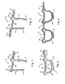
- a surgical staple 11 which includes a pair of legs 13, 15 which have pointed bottom ends 17.
- the legs are interconnected at their upper ends through a crown connector 19.
- a ring 21 At the upper end of the leg 15, there is a ring 21 that is connected thereto by a short stub arm 23.
- the ring 21 extends laterally from the leg 15 in a direction directly away from the leg 13.
- the connector 19 includes a central linear bar 25 that is flanked by a pair of ears 27, 29.
- the ears are loop sections of about 270 degrees each that may be considered to constitute parts of both the connector 19 and the legs 13, 15.
- a staple blank might be laser cut from a flat sheet of a biocompatible metal alloy, and the ring 21 is then twisted 90°. Following edge removal and polishing of the laser-cut blank, the staple has the rounded appearance seen in FIGS. 1, 2 and 3 ; i.e. it has a substantially constant circular cross section, except for the pointed ends 17.
- Both the ring 21 and the ear 27 are proportioned to have a central aperture that is larger in diameter than the circular cross-section of the leg 13 (and the ring 21), so that such can be respectively received therewithin.
- the aperture may be as small as only about 20% greater, but might be about 4 times the size. Generally, it will not be more than about twice the size.
- the ring or loop 21 is aligned so that it lies transverse to the leg 15 to which it is attached; it preferably lies in a plane that is substantially perpendicular to a plane wherein the legs 13,15 lie. Its location at the upper end of the leg 15 is preferably such that it is co-planar with the plane in which the linear bar central portion 25 of the crown connector lies.
- both the bar 25 and the ring 21 will lie juxtaposed with the surface of the tissue into which the implantation occurs.
- the symmetrical ears 27, 29 are also positioned so that the apertures therewithin would similarly lie within this plane; thus, the ear 27 would receive and accommodate a portion of the ring 21 of the last-implanted staple through which the leg 13 would be passed.
- the surgical staple 11 When the surgical staple 11 is fabricated from shape-memory material, it might be laser cut from a flat sheet of biocompatible metal alloy, subjected to chemical, mechanical or electrical surface treatments to polish it, and then suitably treated to endow the staple with shape-memory characteristics so it would revert to the shape shown in Figure 3 . It would then be bent to the shape illustrated in Figure 1 and loaded into a delivery tool.
- the delivery tool operated by a cardiac surgeon, would be used to simply implant each staple with the leg 13 passing through the ring 21 of the last implanted staple so that the linear bar 25 and the ring 21 of this staple would be juxtaposed against the upper surface of the tissue, with a section of the adjacent staple ring 21 being received in the ear 27.
- the staples 11 might be, for example, sized to create a constriction of about 2 mm in the tissue below the surface wherein implantation occurs.
- the crown connector 19, which includes the linear bar 25 and the two ears 27, would be designed to be of a fixed dimension so that only the regions of the legs lying below their interconnections with the lower ends of the ears 27, 29 would bend or curve toward each other to effect the gathering of the tissue. It is in this fashion that the constriction is relegated to regions within the tissue itself, spaced below its surface. As a result, it creates a more uniform contraction or gathering of the tissue and avoids any propensity to tear at the surface.
- the staples which are made out of biocompatible metal alloys, are then implanted using a stapling tool that will effect a curvature to the legs so that they will assume the arcuate shapes shown in Fig. 3 .
- a stapling tool that will effect a curvature to the legs so that they will assume the arcuate shapes shown in Fig. 3 .
- Figure 4 depicts two such interengaged staples 11 as the staples would be employed to create a partial or complete ring about a valve annulus, for example, that of an incompetent mitral valve.
- a partial ring might be employed, it has been found that improvement in an incompetent valve often might be only temporary if the annuloplasty were limited to less than 360 degrees about the perimeter.
- the heart valve tissue when only constricted by a partial ring annuloplasty, may well stretch in other locations, such as the intertrigonal region; as a result, incompetence may return to some degree.
- the first staple or element placed should be one having a pair of such rings.
- a staple 11a which has a second ring 2 1 a extending laterally from the upper end of the leg 13 in the region of the ear 27. Both rings lie in a plane perpendicular to the legs 13,15 which plane includes the linear bar 25.
- a staple 11a is first implanted is having a pair of rings 21,21a.
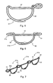
- FIG. 5 Shown in Figure 5 is an alternative embodiment of a surgical staple 31, which is shown in a constricted orientation as in Fig. 3 ; the staple 31 likewise incorporates a pair of legs 33, 35 with a linear crown connector 37 at the upper ends thereof. Its construction allows formation of the staple 31 by bending a metal alloy wire of circular cross section to provide a wireform surgical staple. Other cross-section shaped wires might be used, e.g. a layered metal wire of generally square or wire of non-round cross-section. The wire is shaped such that a similar ear 39 is formed at the upper end of the leg 33; however, the symmetrical ear is omitted.
- a transversely oriented ring 41 is provided by forming a loop from the wire at the opposite end of the connector 37 at the top of the leg 35 and then twisting the wire for 270°, creating a twist-bend 43. The result is such that the looped wire forms a 360 degree ring 41 attached at the twisted joint 43.
- the transverse ring 41 is again oriented so as to lie in substantially the same plane as the linear connector 37, both of which would lie juxtaposed with the upper surface of the tissue in the implanted annuloplasty system.
- the ear 39 would extend above the surface of the tissue and accommodate the pertinent portion of the ring 41 of the last-implanted staple in its central aperture or bight.
- the first staple implanted would have 2 rings 41,41a as the staple 31a shown in Fig. 6 .
- FIG. 7 Three such generally similar staples 31b are illustrated in Figure 7 where they are shown as a part of a chain. The only difference is that, in the staples 31b, the loop 41 is twisted 450° to create a more pronounced twisted joint 43a. Once implanted, the undersurface of the ring 41 and that of the linear connector 37 would be juxtaposed with the surface of the tissue into which the surgical staple is delivered, similar to the staples 11.
- this annuloplasty system provides the surgeon a way to reconfigure an incompetent valve quickly, using simply a loaded delivery tool which will serially deliver individual staples to create an encircling arrangement about the valve that will effect such reconfiguration that the valve leaflets again coapt as desired and intended.
- the surgeon need not individually crimp staples or other plication bands that have been earlier implanted in the tissue, but can quickly simply deliver surgical staples, one after another, simply passing one leg of each staple through the aperture provided by an integral, transverse ring affixed to the upper end of one leg of the last implanted staple.
- the annuloplasty system gives rise to ease, speed and accuracy of operation and allows the surgeon to achieve valve reconfiguration as desired.
- Hernias generally erupt when a weakened location in the abdominal wall stretches and/or tears, which may permit organs inside to pouch outward, often looking like a balloon beneath the skin.
- Another type of hernia evolves as a result of incomplete healing and scaring of an abdominal wall incision, following an intra-abdominal operation; it is termed an "incisional hernia".
- Certain of these hernia types are often corrected by an additional procedure which reinforces the tissues by suturing a flexible surgical mesh material to the abdominal wall or the like.
- a kit comprising a multiple number of the staples 11 or 31 and flexible mesh, synthetic fiber textile material or the like may be used to repair a hernia, but staples of alternative shapes that incorporate not only the interlocking feature but also a so-called shock-absorbing feature can be advantageously employed.
- These alternative staples are likewise used to constrict the body tissue below the surface between two leg entry points that are spaced apart a finite distance as set by each crown connector as described above.
- crown connectors are shaped to allow a potential increase in intra-abdominal pressure to be divided more evenly throughout the entire circumference of the created ring rather than being concentrated in the vicinity of a single staple or a weak location where, with time, dislodging or tearing may often occur
- Such an arrangement which provides some flexing or elastic movement in the chain of staples should better accommodate the occurrence of such momentary rises in abdominal pressure and thereby reduce the recurrence rate of herniorrhaphy procedures, which is currently significantly high.
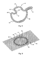
- Figure 8 shows one embodiment of such a shock-absorbing staple 51. It resembles the staple 31 in that it includes two legs 53,55 which are spaced apart by a crown connector 57 with an ear 59 formed atop the leg 53 and a ring 61 formed atop the leg 55. However, instead of the crown connector 57 being formed with a straight linear section 37, it is formed with a major U-shaped bend 63 having a pair of arms 65 interconnected by an arcuate link 67.
- the staples 51 would be implanted into abdominal tissue or the like by protrusion through a reinforcing flexible mesh material patch 69 in the manner schematically shown in Fig. 9 .
- the mesh material patch 69 would have a sufficiently large area to cover the weakness in the abdominal cavity, but likely would not be as oversize as schematically shown; it would usually be tailored by the surgeon by trimming prior to implantation to be about 3-4 cm greater than the defect. With any organs moved back into place by repairing muscle damage, the flexible mesh material patch 69 is secured in contact with the surface of the tissue covering the cavity by creating an encircling ring of staples 51 that borders the region of hernia defect.
- each staple 51 in the encircling ring is such that a U-shape bend 63 lies radially outward of the circle defined by the legs 53,55 of the plurality of staples.
- the legs 53,55 of the plurality of staples can elastically spread-apart as a result of some slight opening of the radius of the arcuate link 67 and bending of the arms 63.
- a shock-absorbing staple 71 which likewise has a pair of legs 73,75 spaced apart a predetermined distance by a crown connector 77; it includes an ear 79 atop the leg 73 and a transverse ring 81 atop the leg 75.
- the ability to momentarily flex and then return to the predetermined original shape is provided by an S-shaped section 83 in the form of 3 legs, oriented transverse to a line drawn between the ear 79 and the ring 81, interconnected by arcuate bends, that forms the major portion of the crown connector 77 and provides the desired springiness.
- Illustrated in Fig. 11 are a multitude of the staples 71 implanted through a patch of the surgical reinforcing flexible mesh material 69 so as to encircle a weakened region of an abdominal cavity.
- Such flexible mesh patches 69 can be woven or knitted or made of other suitable fabric material of the type that has long been used in hernia repair.
- patches are made of polymeric material that is biocompatible, such as polypropylene or polytetrafluoroethylene (PTFE).
- PTFE polytetrafluoroethylene
- Standard surgical stapling has heretofore been used as well as suturing for hernia repair.
- Endoscopic staplers are commercially available to facilitate endoscopic hernia repair, such as the ENDOPATHY ES endoscope which is marketed by the Ethicon division of J&J.
- Staplers of this general type can be adapted to implant either the staples 51 or the staples 71; the design may be such to implant either shape-memory staples or staples made of standard metal alloys or layered metals which will retain the shape established by the stapling tool, subject of course to the elastic region of the crown connectors.
- the flexible polymeric mesh material while providing reinforcing support against movement in a direction transverse to plane thereof (so as to thereby support the weakened abdominal region or the like from bulging outward), allows some inherent stretching movement in the plane thereof.
- the encircling chain of interlocking staples 51 or 71 as shown in Figs. 9 and 11 , creates a perimeter of finite length and thus provide added support .
- the staple construction which provides an elastic, i.e. spring-like or shock-absorbing, section in the crown connector that joins the respective two legs of the staples.
- the staples By choosing a construction material for the staples that will retain the primary shape of the two curved leg portions that are embedded in the body tissue, but which has a modulus of elasticity within a fairly narrow range; the staples remain securely implanted while the U- or S-shaped section will flex in response to the exertion of force on the implanted, interconnected staples.
- the arrangement is such that a momentary interabdominal pressure rise results in forces which are distributed throughout the entire ring so that it spreads and then returns to its original shape upon relaxation of such pressure thereby avoiding potential tearing of the repair.
- Staples might be made of a metal alloy wire or may be laser cut from metal sheets of appropriate thickness and treated to provide them with the desired configuration; for example, stainless steel 316L staples having a cross sectional diameter of about 0.5 to 1.2 mm and a modulus of elasticity of about 193 GPa (giga Pascal) should exhibit the desired springiness.
- staples 51 may be made from cobalt-nickel-chromium alloy No. L605 having a diameter of about 0.6-1.2 mm and a modulus of elasticity of about 206 GPa.
- a target range for modulus of elasticity for such staples might be between about 190 and about 210 GPa.
- they may be made from medical-grade Nitinol wire of about 0.8-1.2 mm diameter having shape-memory characteristics.
- a kit would be provided that will include (a) multiple staples of the shape shown in Figs. 8 or 10 , (b) one such staple having two rings, one at the upper end of each of the legs, (c) one staple without a transverse ring at the upper end of either leg, and (d) a patch of flexible surgical reinforcing fabric.
- central connector having a U-shape bend and an S-shape bend
- other such non-straight-line shapes may be used to provide precise spacing between the upper ends of the legs when desired to allow some limited flex in the plane of the ultimate ring created by the crown connectors which permit some slight spreading of the implanted legs to follow the physiological movement of the tissue, creating what might be referred to as a "breathing ring”.
Landscapes
- Health & Medical Sciences (AREA)
- Life Sciences & Earth Sciences (AREA)
- Cardiology (AREA)
- Veterinary Medicine (AREA)
- Public Health (AREA)
- Biomedical Technology (AREA)
- Heart & Thoracic Surgery (AREA)
- Engineering & Computer Science (AREA)
- Surgery (AREA)
- Animal Behavior & Ethology (AREA)
- General Health & Medical Sciences (AREA)
- Medical Informatics (AREA)
- Molecular Biology (AREA)
- Nuclear Medicine, Radiotherapy & Molecular Imaging (AREA)
- Oral & Maxillofacial Surgery (AREA)
- Transplantation (AREA)
- Vascular Medicine (AREA)
- Prostheses (AREA)
- Surgical Instruments (AREA)
Applications Claiming Priority (2)
| Application Number | Priority Date | Filing Date | Title |
|---|---|---|---|
| US4663508P | 2008-04-21 | 2008-04-21 | |
| PCT/IB2009/051473 WO2009130631A2 (en) | 2008-04-21 | 2009-04-07 | Surgical stapling systems |
Publications (2)
| Publication Number | Publication Date |
|---|---|
| EP2273928A2 EP2273928A2 (en) | 2011-01-19 |
| EP2273928B1 true EP2273928B1 (en) | 2012-03-21 |
Family
ID=41203757
Family Applications (1)
| Application Number | Title | Priority Date | Filing Date |
|---|---|---|---|
| EP09734313A Not-in-force EP2273928B1 (en) | 2008-04-21 | 2009-04-07 | Surgical stapling systems |
Country Status (7)
| Country | Link |
|---|---|
| US (1) | US8475491B2 (enExample) |
| EP (1) | EP2273928B1 (enExample) |
| JP (1) | JP5324645B2 (enExample) |
| AT (1) | ATE549978T1 (enExample) |
| AU (1) | AU2009239670B2 (enExample) |
| CA (1) | CA2722233C (enExample) |
| WO (1) | WO2009130631A2 (enExample) |
Cited By (16)
| Publication number | Priority date | Publication date | Assignee | Title |
|---|---|---|---|---|
| US9592122B2 (en) | 2009-05-07 | 2017-03-14 | Valtech Cardio, Ltd | Annuloplasty ring with intra-ring anchoring |
| US10856984B2 (en) | 2017-08-25 | 2020-12-08 | Neovasc Tiara Inc. | Sequentially deployed transcatheter mitral valve prosthesis |
| US10940001B2 (en) | 2012-05-30 | 2021-03-09 | Neovasc Tiara Inc. | Methods and apparatus for loading a prosthesis onto a delivery system |
| US11311376B2 (en) | 2019-06-20 | 2022-04-26 | Neovase Tiara Inc. | Low profile prosthetic mitral valve |
| US11357622B2 (en) | 2016-01-29 | 2022-06-14 | Neovase Tiara Inc. | Prosthetic valve for avoiding obstruction of outflow |
| US11389291B2 (en) | 2013-04-04 | 2022-07-19 | Neovase Tiara Inc. | Methods and apparatus for delivering a prosthetic valve to a beating heart |
| US11413139B2 (en) | 2011-11-23 | 2022-08-16 | Neovasc Tiara Inc. | Sequentially deployed transcatheter mitral valve prosthesis |
| US11419720B2 (en) | 2010-05-05 | 2022-08-23 | Neovasc Tiara Inc. | Transcatheter mitral valve prosthesis |
| US11464631B2 (en) | 2016-11-21 | 2022-10-11 | Neovasc Tiara Inc. | Methods and systems for rapid retraction of a transcatheter heart valve delivery system |
| US11491006B2 (en) | 2019-04-10 | 2022-11-08 | Neovasc Tiara Inc. | Prosthetic valve with natural blood flow |
| US11497602B2 (en) | 2012-02-14 | 2022-11-15 | Neovasc Tiara Inc. | Methods and apparatus for engaging a valve prosthesis with tissue |
| US11602429B2 (en) | 2019-04-01 | 2023-03-14 | Neovasc Tiara Inc. | Controllably deployable prosthetic valve |
| US11737872B2 (en) | 2018-11-08 | 2023-08-29 | Neovasc Tiara Inc. | Ventricular deployment of a transcatheter mitral valve prosthesis |
| US11779742B2 (en) | 2019-05-20 | 2023-10-10 | Neovasc Tiara Inc. | Introducer with hemostasis mechanism |
| US11998447B2 (en) | 2019-03-08 | 2024-06-04 | Neovasc Tiara Inc. | Retrievable prosthesis delivery system |
| US12109111B2 (en) | 2015-12-15 | 2024-10-08 | Neovasc Tiara Inc. | Transseptal delivery system |
Families Citing this family (126)
| Publication number | Priority date | Publication date | Assignee | Title |
|---|---|---|---|---|
| US8123801B2 (en) * | 2001-12-21 | 2012-02-28 | QuickRing Medical Technologies, Ltd. | Implantation system for annuloplasty rings |
| WO2006097931A2 (en) | 2005-03-17 | 2006-09-21 | Valtech Cardio, Ltd. | Mitral valve treatment techniques |
| US8333777B2 (en) | 2005-04-22 | 2012-12-18 | Benvenue Medical, Inc. | Catheter-based tissue remodeling devices and methods |
| US8951285B2 (en) | 2005-07-05 | 2015-02-10 | Mitralign, Inc. | Tissue anchor, anchoring system and methods of using the same |
| US9883943B2 (en) | 2006-12-05 | 2018-02-06 | Valtech Cardio, Ltd. | Implantation of repair devices in the heart |
| US11259924B2 (en) | 2006-12-05 | 2022-03-01 | Valtech Cardio Ltd. | Implantation of repair devices in the heart |
| US11660190B2 (en) | 2007-03-13 | 2023-05-30 | Edwards Lifesciences Corporation | Tissue anchors, systems and methods, and devices |
| US8382829B1 (en) | 2008-03-10 | 2013-02-26 | Mitralign, Inc. | Method to reduce mitral regurgitation by cinching the commissure of the mitral valve |
| EP2296744B1 (en) | 2008-06-16 | 2019-07-31 | Valtech Cardio, Ltd. | Annuloplasty devices |
| WO2010073246A2 (en) | 2008-12-22 | 2010-07-01 | Valtech Cardio, Ltd. | Adjustable annuloplasty devices and adjustment mechanisms therefor |
| US8241351B2 (en) | 2008-12-22 | 2012-08-14 | Valtech Cardio, Ltd. | Adjustable partial annuloplasty ring and mechanism therefor |
| US9011530B2 (en) | 2008-12-22 | 2015-04-21 | Valtech Cardio, Ltd. | Partially-adjustable annuloplasty structure |
| US8911494B2 (en) | 2009-05-04 | 2014-12-16 | Valtech Cardio, Ltd. | Deployment techniques for annuloplasty ring |
| US10517719B2 (en) | 2008-12-22 | 2019-12-31 | Valtech Cardio, Ltd. | Implantation of repair devices in the heart |
| US9713471B2 (en) * | 2009-01-26 | 2017-07-25 | Ethicon Endo-Surgery, Inc. | Surgical device with tandem fasteners |
| US8353956B2 (en) | 2009-02-17 | 2013-01-15 | Valtech Cardio, Ltd. | Actively-engageable movement-restriction mechanism for use with an annuloplasty structure |
| EP2419028B1 (en) * | 2009-04-15 | 2019-02-06 | ZSX Medical, LLC | Surgical device |
| US9968452B2 (en) | 2009-05-04 | 2018-05-15 | Valtech Cardio, Ltd. | Annuloplasty ring delivery cathethers |
| US12485010B2 (en) | 2009-05-07 | 2025-12-02 | Edwards Lifesciences Innovation (Israel) Ltd. | Multiple anchor delivery tool |
| EP2445417A2 (en) | 2009-06-26 | 2012-05-02 | QuickRing Medical Technologies Ltd. | Surgical stapler |
| US10098737B2 (en) | 2009-10-29 | 2018-10-16 | Valtech Cardio, Ltd. | Tissue anchor for annuloplasty device |
| US9180007B2 (en) | 2009-10-29 | 2015-11-10 | Valtech Cardio, Ltd. | Apparatus and method for guide-wire based advancement of an adjustable implant |
| EP2506777B1 (en) | 2009-12-02 | 2020-11-25 | Valtech Cardio, Ltd. | Combination of spool assembly coupled to a helical anchor and delivery tool for implantation thereof |
| US8870950B2 (en) | 2009-12-08 | 2014-10-28 | Mitral Tech Ltd. | Rotation-based anchoring of an implant |
| US11653910B2 (en) | 2010-07-21 | 2023-05-23 | Cardiovalve Ltd. | Helical anchor implantation |
| EP2600799B1 (en) | 2010-08-04 | 2017-05-17 | ValCare, Inc. | Percutaneous transcatheter repair of heart valves |
| DE102012100086A1 (de) * | 2011-01-07 | 2012-08-02 | Z-Medical Gmbh & Co. Kg | Chirurgisches Instrument |
| US9155536B1 (en) * | 2011-04-26 | 2015-10-13 | Cardica, Inc. | Circular stapler |
| US9402721B2 (en) | 2011-06-01 | 2016-08-02 | Valcare, Inc. | Percutaneous transcatheter repair of heart valves via trans-apical access |
| EP3725269A1 (en) | 2011-06-23 | 2020-10-21 | Valtech Cardio, Ltd. | Closure element for use with annuloplasty structure |
| US10792152B2 (en) | 2011-06-23 | 2020-10-06 | Valtech Cardio, Ltd. | Closed band for percutaneous annuloplasty |
| US8858623B2 (en) | 2011-11-04 | 2014-10-14 | Valtech Cardio, Ltd. | Implant having multiple rotational assemblies |
| EP3970627B1 (en) | 2011-11-08 | 2023-12-20 | Edwards Lifesciences Innovation (Israel) Ltd. | Controlled steering functionality for implant-delivery tool |
| WO2013088327A1 (en) | 2011-12-12 | 2013-06-20 | David Alon | Heart valve repair device |
| US9180008B2 (en) | 2012-02-29 | 2015-11-10 | Valcare, Inc. | Methods, devices, and systems for percutaneously anchoring annuloplasty rings |
| US9839519B2 (en) | 2012-02-29 | 2017-12-12 | Valcare, Inc. | Percutaneous annuloplasty system with anterior-posterior adjustment |
| US10226270B2 (en) | 2012-08-10 | 2019-03-12 | W. L. Gore & Associates, Inc. | Microanchors for anchoring devices to body tissues |
| CA2885354A1 (en) | 2012-09-29 | 2014-04-03 | Mitralign, Inc. | Plication lock delivery system and method of use thereof |
| US9949828B2 (en) | 2012-10-23 | 2018-04-24 | Valtech Cardio, Ltd. | Controlled steering functionality for implant-delivery tool |
| EP2911593B1 (en) | 2012-10-23 | 2020-03-25 | Valtech Cardio, Ltd. | Percutaneous tissue anchor techniques |
| WO2014087402A1 (en) | 2012-12-06 | 2014-06-12 | Valtech Cardio, Ltd. | Techniques for guide-wire based advancement of a tool |
| EP2948103B1 (en) | 2013-01-24 | 2022-12-07 | Cardiovalve Ltd | Ventricularly-anchored prosthetic valves |
| WO2014134183A1 (en) | 2013-02-26 | 2014-09-04 | Mitralign, Inc. | Devices and methods for percutaneous tricuspid valve repair |
| US10449333B2 (en) | 2013-03-14 | 2019-10-22 | Valtech Cardio, Ltd. | Guidewire feeder |
| WO2014145399A1 (en) | 2013-03-15 | 2014-09-18 | Valcare, Inc. | Systems and methods for delivery of annuloplasty rings |
| US9724195B2 (en) | 2013-03-15 | 2017-08-08 | Mitralign, Inc. | Translation catheters and systems |
| US10813751B2 (en) | 2013-05-22 | 2020-10-27 | Valcare, Inc. | Transcatheter prosthetic valve for mitral or tricuspid valve replacement |
| EP3003187B1 (en) | 2013-05-24 | 2023-11-08 | Valcare, Inc. | Heart and peripheral vascular valve replacement in conjunction with a support ring |
| EP3013253B1 (en) * | 2013-06-28 | 2021-01-06 | ValCare, Inc. | Device for securing an article to a tissue |
| US10070857B2 (en) | 2013-08-31 | 2018-09-11 | Mitralign, Inc. | Devices and methods for locating and implanting tissue anchors at mitral valve commissure |
| US10299793B2 (en) | 2013-10-23 | 2019-05-28 | Valtech Cardio, Ltd. | Anchor magazine |
| WO2015063609A2 (en) | 2013-11-04 | 2015-05-07 | Simcha Milo | Surgical stapler |
| US9724092B2 (en) | 2013-12-23 | 2017-08-08 | Ethicon Llc | Modular surgical instruments |
| US20150173756A1 (en) | 2013-12-23 | 2015-06-25 | Ethicon Endo-Surgery, Inc. | Surgical cutting and stapling methods |
| US9839428B2 (en) | 2013-12-23 | 2017-12-12 | Ethicon Llc | Surgical cutting and stapling instruments with independent jaw control features |
| US9687232B2 (en) | 2013-12-23 | 2017-06-27 | Ethicon Llc | Surgical staples |
| US9610162B2 (en) | 2013-12-26 | 2017-04-04 | Valtech Cardio, Ltd. | Implantation of flexible implant |
| US10499908B2 (en) | 2014-03-04 | 2019-12-10 | Maquet Cardiovascular Llc | Surgical implant and method and instrument for installing the same |
| WO2015134682A1 (en) | 2014-03-04 | 2015-09-11 | Maquet Cardiovascular Llc | Surgical implant and method and instrument for installing the same |
| EP3174502B1 (en) | 2014-07-30 | 2022-04-06 | Cardiovalve Ltd | Apparatus for implantation of an articulatable prosthetic valve |
| EP4331503A3 (en) | 2014-10-14 | 2024-06-05 | Edwards Lifesciences Innovation (Israel) Ltd. | Leaflet-restraining techniques |
| US9895212B2 (en) * | 2014-10-31 | 2018-02-20 | Prevent Patch LLC | Devices and methods for preventing incisional hernias |
| EP3253333B1 (en) | 2015-02-05 | 2024-04-03 | Cardiovalve Ltd | Prosthetic valve with axially-sliding frames |
| US20160256269A1 (en) | 2015-03-05 | 2016-09-08 | Mitralign, Inc. | Devices for treating paravalvular leakage and methods use thereof |
| SG11201708397PA (en) | 2015-04-30 | 2017-11-29 | Valtech Cardio Ltd | Annuloplasty technologies |
| US11103248B2 (en) | 2015-08-26 | 2021-08-31 | Cilag Gmbh International | Surgical staples for minimizing staple roll |
| JP6858754B2 (ja) | 2015-08-26 | 2021-04-14 | エシコン エルエルシーEthicon LLC | 様々な組織圧縮用隙間及びステープル成形用隙間を含むステープルカートリッジアセンブリ |
| MX2022009705A (es) | 2015-08-26 | 2022-11-07 | Ethicon Llc | Metodo para formar una grapa contra un yunque de un instrumento de engrapado quirurgico. |
| MX2018002388A (es) | 2015-08-26 | 2018-08-01 | Ethicon Llc | Tiras de grapas quirurgicas para permitir propiedades variables de la grapa y facilitar la carga del cartucho. |
| US10251648B2 (en) | 2015-09-02 | 2019-04-09 | Ethicon Llc | Surgical staple cartridge staple drivers with central support features |
| MX2022006189A (es) | 2015-09-02 | 2022-06-16 | Ethicon Llc | Configuraciones de grapas quirurgicas con superficies de leva situadas entre porciones que soportan grapas quirurgicas. |
| JP6823321B2 (ja) * | 2015-10-09 | 2021-02-03 | 国立大学法人東海国立大学機構 | 生体吸収性ステープル |
| US10751182B2 (en) | 2015-12-30 | 2020-08-25 | Edwards Lifesciences Corporation | System and method for reshaping right heart |
| EP3397207B1 (en) | 2015-12-30 | 2026-04-01 | Edwards Lifesciences Corporation | System for reducing tricuspid regurgitation |
| US10531866B2 (en) | 2016-02-16 | 2020-01-14 | Cardiovalve Ltd. | Techniques for providing a replacement valve and transseptal communication |
| US10702274B2 (en) | 2016-05-26 | 2020-07-07 | Edwards Lifesciences Corporation | Method and system for closing left atrial appendage |
| USD850617S1 (en) | 2016-06-24 | 2019-06-04 | Ethicon Llc | Surgical fastener cartridge |
| US10675024B2 (en) | 2016-06-24 | 2020-06-09 | Ethicon Llc | Staple cartridge comprising overdriven staples |
| USD847989S1 (en) | 2016-06-24 | 2019-05-07 | Ethicon Llc | Surgical fastener cartridge |
| USD826405S1 (en) | 2016-06-24 | 2018-08-21 | Ethicon Llc | Surgical fastener |
| BR112018076831B1 (pt) | 2016-06-24 | 2023-01-31 | Ethicon Llc | Sistema de grampeamento cirúrgico |
| JP6957532B2 (ja) | 2016-06-24 | 2021-11-02 | エシコン エルエルシーEthicon LLC | ワイヤステープル及び打ち抜き加工ステープルを含むステープルカートリッジ |
| GB201611910D0 (en) | 2016-07-08 | 2016-08-24 | Valtech Cardio Ltd | Adjustable annuloplasty device with alternating peaks and troughs |
| US20190231525A1 (en) | 2016-08-01 | 2019-08-01 | Mitraltech Ltd. | Minimally-invasive delivery systems |
| CN109789018B (zh) | 2016-08-10 | 2022-04-26 | 卡迪尔维尔福股份有限公司 | 具有同轴框架的人工瓣膜 |
| CN107753153B (zh) | 2016-08-15 | 2022-05-31 | 沃卡尔有限公司 | 用于治疗心脏瓣膜关闭不全的装置和方法 |
| US10687810B2 (en) | 2016-12-21 | 2020-06-23 | Ethicon Llc | Stepped staple cartridge with tissue retention and gap setting features |
| US11684367B2 (en) | 2016-12-21 | 2023-06-27 | Cilag Gmbh International | Stepped assembly having and end-of-life indicator |
| US10945727B2 (en) | 2016-12-21 | 2021-03-16 | Ethicon Llc | Staple cartridge with deformable driver retention features |
| US10537324B2 (en) | 2016-12-21 | 2020-01-21 | Ethicon Llc | Stepped staple cartridge with asymmetrical staples |
| US10993715B2 (en) | 2016-12-21 | 2021-05-04 | Ethicon Llc | Staple cartridge comprising staples with different clamping breadths |
| CN108618871A (zh) | 2017-03-17 | 2018-10-09 | 沃卡尔有限公司 | 具有多方向锚部的二尖瓣或三尖瓣修复系统 |
| US11045627B2 (en) | 2017-04-18 | 2021-06-29 | Edwards Lifesciences Corporation | Catheter system with linear actuation control mechanism |
| US10524784B2 (en) | 2017-05-05 | 2020-01-07 | Covidien Lp | Surgical staples with expandable backspan |
| US11517325B2 (en) | 2017-06-20 | 2022-12-06 | Cilag Gmbh International | Closed loop feedback control of motor velocity of a surgical stapling and cutting instrument based on measured displacement distance traveled over a specified time interval |
| US12064347B2 (en) | 2017-08-03 | 2024-08-20 | Cardiovalve Ltd. | Prosthetic heart valve |
| US11793633B2 (en) | 2017-08-03 | 2023-10-24 | Cardiovalve Ltd. | Prosthetic heart valve |
| US12458493B2 (en) | 2017-09-19 | 2025-11-04 | Cardiovalve Ltd. | Prosthetic heart valve and delivery systems and methods |
| US10835221B2 (en) | 2017-11-02 | 2020-11-17 | Valtech Cardio, Ltd. | Implant-cinching devices and systems |
| US11135062B2 (en) | 2017-11-20 | 2021-10-05 | Valtech Cardio Ltd. | Cinching of dilated heart muscle |
| WO2019145947A1 (en) | 2018-01-24 | 2019-08-01 | Valtech Cardio, Ltd. | Contraction of an annuloplasty structure |
| EP3743014B1 (en) | 2018-01-26 | 2023-07-19 | Edwards Lifesciences Innovation (Israel) Ltd. | Techniques for facilitating heart valve tethering and chord replacement |
| CN120000269A (zh) | 2018-07-12 | 2025-05-16 | 爱德华兹生命科学创新(以色列)有限公司 | 瓣环成形系统及其锁定工具 |
| CN113556983A (zh) * | 2018-10-01 | 2021-10-26 | 基托泰克医疗股份有限公司 | 包括微结构的组织护理器具 |
| WO2020117842A1 (en) | 2018-12-03 | 2020-06-11 | Valcare, Inc. | Stabilizing and adjusting tool for controlling a minimally invasive mitral / tricuspid valve repair system |
| JP2022514399A (ja) * | 2018-12-18 | 2022-02-10 | ボルダー サージカル,リミティド ライアビリティ カンパニー | 外科用ステープラ及び関連する方法 |
| AU2020284630A1 (en) | 2019-05-29 | 2021-11-18 | Edwards Lifesciences Innovation (Israel) Ltd. | Tissue anchor handling systems and methods |
| IL288722B2 (en) | 2019-06-11 | 2026-02-01 | Valcare Inc | Annuloplasty ring with posterior leaflet for minimally invasive treatment |
| CN113692253B (zh) | 2019-06-11 | 2024-10-29 | 沃卡尔医药有限公司 | 用于递送腱索置换系统的系统和方法 |
| IL289733B2 (en) | 2019-07-15 | 2026-02-01 | Valcare Inc | Transcatheter bioprosthesis part and support structure |
| US12502167B2 (en) | 2019-07-16 | 2025-12-23 | Edwards Lifesciences Corporation | Tissue remodeling systems and methods |
| US12364606B2 (en) | 2019-07-23 | 2025-07-22 | Edwards Lifesciences Innovation (Israel) Ltd. | Fluoroscopic visualization of heart valve anatomy |
| CA3141295A1 (en) | 2019-07-23 | 2021-01-28 | Valtech Cardio, Ltd. | Contraction of an annuloplasty structure |
| WO2021038560A1 (en) | 2019-08-28 | 2021-03-04 | Valtech Cardio, Ltd. | Low-profile steerable catheter |
| EP4021350B1 (en) | 2019-08-30 | 2024-12-18 | Edwards Lifesciences Innovation (Israel) Ltd. | Anchor channel tip |
| KR20220066398A (ko) | 2019-09-25 | 2022-05-24 | 카디악 임플란츠 엘엘씨 | 심장 판막 고리 감소 시스템 |
| KR20220122966A (ko) | 2019-10-29 | 2022-09-05 | 에드워즈 라이프사이언시스 이노베이션 (이스라엘) 리미티드 | 고리 성형술 및 조직 앵커 기술 |
| EP4096529B1 (en) | 2020-03-23 | 2025-05-07 | Edwards Lifesciences Innovation (Israel) Ltd. | Self-locking winch |
| JP2023527304A (ja) | 2020-05-20 | 2023-06-28 | カーディアック・インプランツ・エルエルシー | 心臓弁輪に打ち込まれるアンカそれぞれを独立的に制御することによる心臓弁輪の直径の減少 |
| EP4606322A1 (en) | 2020-06-19 | 2025-08-27 | Edwards Lifesciences Innovation (Israel) Ltd. | Self-stopping tissue anchors |
| WO2022026738A1 (en) * | 2020-07-29 | 2022-02-03 | Magstape Llc | Biometallic alloy surgical staples and methods |
| CN114848099B (zh) * | 2020-08-07 | 2025-02-21 | 浙江医高医疗科技有限公司 | 缝合钉以及具有其的包皮环切吻合器 |
| US12357459B2 (en) | 2020-12-03 | 2025-07-15 | Cardiovalve Ltd. | Transluminal delivery system |
| US20230072138A1 (en) * | 2021-09-08 | 2023-03-09 | Covidien Lp | Surgical fastener having a base and a leg |
| US20230115466A1 (en) * | 2021-09-16 | 2023-04-13 | Simcha Milo | Apparatus and methods for bariatric surgery |
| WO2024254088A1 (en) * | 2023-06-05 | 2024-12-12 | Cannuflow, Inc. | Staple and driver for tendon stapling apparatus |
Family Cites Families (20)
| Publication number | Priority date | Publication date | Assignee | Title |
|---|---|---|---|---|
| US4347847A (en) | 1980-06-06 | 1982-09-07 | Usher Francis C | Method of hernia repair |
| DE3204532C2 (de) | 1982-02-10 | 1983-12-08 | B. Braun Melsungen Ag, 3508 Melsungen | Chirurgische Hautklammer |
| US4887601A (en) | 1987-11-06 | 1989-12-19 | Ophthalmic Ventures Limited Partnership | Adjustable surgical staple and method of using the same |
| US5122155A (en) | 1990-10-11 | 1992-06-16 | Eberbach Mark A | Hernia repair apparatus and method of use |
| FR2668361A1 (fr) * | 1990-10-30 | 1992-04-30 | Mai Christian | Agrafe et plaque d'osteosynthese a compression dynamique auto-retentive. |
| US5289963A (en) | 1991-10-18 | 1994-03-01 | United States Surgical Corporation | Apparatus and method for applying surgical staples to attach an object to body tissue |
| US5147374A (en) | 1991-12-05 | 1992-09-15 | Alfredo Fernandez | Prosthetic mesh patch for hernia repair |
| US5947999A (en) * | 1996-12-03 | 1999-09-07 | Groiso; Jorge A. | Surgical clip and method |
| AU2001271411A1 (en) | 2000-06-23 | 2002-01-08 | Viacor Incorporated | Automated annular plication for mitral valve repair |
| JP4526206B2 (ja) * | 2001-04-25 | 2010-08-18 | 株式会社トップ | 外科用ステープル |
| IES20010547A2 (en) | 2001-06-07 | 2002-12-11 | Christy Cummins | Surgical Staple |
| US20060020336A1 (en) * | 2001-10-23 | 2006-01-26 | Liddicoat John R | Automated annular plication for mitral valve repair |
| WO2003053289A1 (en) * | 2001-12-21 | 2003-07-03 | Simcha Milo | Implantation system for annuloplasty rings |
| US20050283190A1 (en) | 2004-06-16 | 2005-12-22 | Huitema Thomas W | Surgical fastener |
| WO2006082586A2 (en) | 2005-02-04 | 2006-08-10 | Moshe Dudai | Staples, staplers, anastomosis devices, and methods for their applications |
| US20060291981A1 (en) * | 2005-06-02 | 2006-12-28 | Viola Frank J | Expandable backspan staple |
| JP5027816B2 (ja) * | 2005-10-03 | 2012-09-19 | バロセンス、インク | 内視鏡的ひだ形成装置および方法 |
| CN101460103A (zh) * | 2006-04-13 | 2009-06-17 | 凯希特许有限公司 | 医疗闭合夹系统及方法 |
| US7473258B2 (en) | 2007-03-08 | 2009-01-06 | Cardica, Inc. | Surgical stapler |
| JP2010207289A (ja) * | 2009-03-06 | 2010-09-24 | Kohei Kubota | 医療用打ち込み式ステープル |
-
2009
- 2009-04-07 AU AU2009239670A patent/AU2009239670B2/en not_active Ceased
- 2009-04-07 WO PCT/IB2009/051473 patent/WO2009130631A2/en not_active Ceased
- 2009-04-07 EP EP09734313A patent/EP2273928B1/en not_active Not-in-force
- 2009-04-07 JP JP2011505619A patent/JP5324645B2/ja not_active Expired - Fee Related
- 2009-04-07 CA CA2722233A patent/CA2722233C/en active Active
- 2009-04-07 AT AT09734313T patent/ATE549978T1/de active
-
2010
- 2010-10-19 US US12/907,698 patent/US8475491B2/en not_active Expired - Fee Related
Cited By (26)
| Publication number | Priority date | Publication date | Assignee | Title |
|---|---|---|---|---|
| US9592122B2 (en) | 2009-05-07 | 2017-03-14 | Valtech Cardio, Ltd | Annuloplasty ring with intra-ring anchoring |
| US12611303B2 (en) | 2010-05-05 | 2026-04-28 | Neovasc Tiara Inc. | Transcatheter mitral valve prosthesis |
| US11419720B2 (en) | 2010-05-05 | 2022-08-23 | Neovasc Tiara Inc. | Transcatheter mitral valve prosthesis |
| US12053369B2 (en) | 2011-11-23 | 2024-08-06 | Neovasc Tiara Inc. | Sequentially deployed transcatheter mitral valve prosthesis |
| US11413139B2 (en) | 2011-11-23 | 2022-08-16 | Neovasc Tiara Inc. | Sequentially deployed transcatheter mitral valve prosthesis |
| US12138159B2 (en) | 2012-02-14 | 2024-11-12 | Neovasc Tiara Inc. | Methods and apparatus for engaging a valve prosthesis with tissue |
| US11497602B2 (en) | 2012-02-14 | 2022-11-15 | Neovasc Tiara Inc. | Methods and apparatus for engaging a valve prosthesis with tissue |
| US11617650B2 (en) | 2012-05-30 | 2023-04-04 | Neovasc Tiara Inc. | Methods and apparatus for loading a prosthesis onto a delivery system |
| US10940001B2 (en) | 2012-05-30 | 2021-03-09 | Neovasc Tiara Inc. | Methods and apparatus for loading a prosthesis onto a delivery system |
| US11389294B2 (en) | 2012-05-30 | 2022-07-19 | Neovasc Tiara Inc. | Methods and apparatus for loading a prosthesis onto a delivery system |
| US11389291B2 (en) | 2013-04-04 | 2022-07-19 | Neovase Tiara Inc. | Methods and apparatus for delivering a prosthetic valve to a beating heart |
| US12109111B2 (en) | 2015-12-15 | 2024-10-08 | Neovasc Tiara Inc. | Transseptal delivery system |
| US11357622B2 (en) | 2016-01-29 | 2022-06-14 | Neovase Tiara Inc. | Prosthetic valve for avoiding obstruction of outflow |
| US12193932B2 (en) | 2016-01-29 | 2025-01-14 | Neovasc Tiara Inc. | Prosthetic valve for avoiding obstruction of outflow |
| US12201524B2 (en) | 2016-11-21 | 2025-01-21 | Neovasc Tiara Inc. | Methods and systems for rapid retraction of a transcatheter heart valve delivery system |
| US11464631B2 (en) | 2016-11-21 | 2022-10-11 | Neovasc Tiara Inc. | Methods and systems for rapid retraction of a transcatheter heart valve delivery system |
| US11793640B2 (en) | 2017-08-25 | 2023-10-24 | Neovasc Tiara Inc. | Sequentially deployed transcatheter mitral valve prosthesis |
| US10856984B2 (en) | 2017-08-25 | 2020-12-08 | Neovasc Tiara Inc. | Sequentially deployed transcatheter mitral valve prosthesis |
| US11737872B2 (en) | 2018-11-08 | 2023-08-29 | Neovasc Tiara Inc. | Ventricular deployment of a transcatheter mitral valve prosthesis |
| US11998447B2 (en) | 2019-03-08 | 2024-06-04 | Neovasc Tiara Inc. | Retrievable prosthesis delivery system |
| US11602429B2 (en) | 2019-04-01 | 2023-03-14 | Neovasc Tiara Inc. | Controllably deployable prosthetic valve |
| US12036117B2 (en) | 2019-04-10 | 2024-07-16 | Neovasc Tiara Inc. | Prosthetic valve with natural blood flow |
| US11491006B2 (en) | 2019-04-10 | 2022-11-08 | Neovasc Tiara Inc. | Prosthetic valve with natural blood flow |
| US11779742B2 (en) | 2019-05-20 | 2023-10-10 | Neovasc Tiara Inc. | Introducer with hemostasis mechanism |
| US11931254B2 (en) | 2019-06-20 | 2024-03-19 | Neovasc Tiara Inc. | Low profile prosthetic mitral valve |
| US11311376B2 (en) | 2019-06-20 | 2022-04-26 | Neovase Tiara Inc. | Low profile prosthetic mitral valve |
Also Published As
| Publication number | Publication date |
|---|---|
| JP2011518017A (ja) | 2011-06-23 |
| CA2722233A1 (en) | 2009-10-29 |
| WO2009130631A3 (en) | 2009-12-23 |
| WO2009130631A2 (en) | 2009-10-29 |
| AU2009239670B2 (en) | 2013-11-14 |
| AU2009239670A1 (en) | 2009-10-29 |
| CA2722233C (en) | 2017-12-05 |
| JP5324645B2 (ja) | 2013-10-23 |
| EP2273928A2 (en) | 2011-01-19 |
| US20110034953A1 (en) | 2011-02-10 |
| US8475491B2 (en) | 2013-07-02 |
| ATE549978T1 (de) | 2012-04-15 |
Similar Documents
| Publication | Publication Date | Title |
|---|---|---|
| EP2273928B1 (en) | Surgical stapling systems | |
| US8123801B2 (en) | Implantation system for annuloplasty rings | |
| EP2293739B1 (en) | Heart valve repair device | |
| EP1465555B1 (en) | Implantation system for annuloplasty rings | |
| EP2517674B1 (en) | Implantable vascular device | |
| CN103249376B (zh) | 减少裂开的瓣膜成形环 | |
| US7758491B2 (en) | Method and apparatus for the surgical treatment of congestive heart failure | |
| US7628803B2 (en) | Implantable vascular device | |
| EP1251805B1 (en) | Implantable vascular device | |
| CN112423709A (zh) | 心脏瓣膜修复的方法和装置 | |
| US20010039450A1 (en) | Implantable vascular device | |
| AU2001238038A1 (en) | Implantable vascular device | |
| JP7826458B2 (ja) | 人工腱索を心臓組織に固定するためのデバイス、システム、および方法 | |
| US20150057491A1 (en) | Medical device and method of delivering the medical device | |
| US10973662B2 (en) | Methods and devices for heart valve repair | |
| AU2013276969A1 (en) | Annuloplasty ring and method |
Legal Events
| Date | Code | Title | Description |
|---|---|---|---|
| PUAI | Public reference made under article 153(3) epc to a published international application that has entered the european phase |
Free format text: ORIGINAL CODE: 0009012 |
|
| 17P | Request for examination filed |
Effective date: 20101119 |
|
| AK | Designated contracting states |
Kind code of ref document: A2 Designated state(s): AT BE BG CH CY CZ DE DK EE ES FI FR GB GR HR HU IE IS IT LI LT LU LV MC MK MT NL NO PL PT RO SE SI SK TR |
|
| RAP1 | Party data changed (applicant data changed or rights of an application transferred) |
Owner name: QUICKRING MEDICAL TECHNOLOGIES LTD. |
|
| RIN1 | Information on inventor provided before grant (corrected) |
Inventor name: QUICKRING MEDICAL TECHNOLOGIES LTD. |
|
| DAX | Request for extension of the european patent (deleted) | ||
| GRAP | Despatch of communication of intention to grant a patent |
Free format text: ORIGINAL CODE: EPIDOSNIGR1 |
|
| GRAS | Grant fee paid |
Free format text: ORIGINAL CODE: EPIDOSNIGR3 |
|
| GRAA | (expected) grant |
Free format text: ORIGINAL CODE: 0009210 |
|
| AK | Designated contracting states |
Kind code of ref document: B1 Designated state(s): AT BE BG CH CY CZ DE DK EE ES FI FR GB GR HR HU IE IS IT LI LT LU LV MC MK MT NL NO PL PT RO SE SI SK TR |
|
| REG | Reference to a national code |
Ref country code: GB Ref legal event code: FG4D |
|
| RIN1 | Information on inventor provided before grant (corrected) |
Inventor name: MILO, SIMCHA |
|
| REG | Reference to a national code |
Ref country code: CH Ref legal event code: EP |
|
| REG | Reference to a national code |
Ref country code: IE Ref legal event code: FG4D |
|
| REG | Reference to a national code |
Ref country code: AT Ref legal event code: REF Ref document number: 549978 Country of ref document: AT Kind code of ref document: T Effective date: 20120415 |
|
| REG | Reference to a national code |
Ref country code: DE Ref legal event code: R096 Ref document number: 602009006023 Country of ref document: DE Effective date: 20120516 |
|
| REG | Reference to a national code |
Ref country code: NL Ref legal event code: VDEP Effective date: 20120321 |
|
| PG25 | Lapsed in a contracting state [announced via postgrant information from national office to epo] |
Ref country code: LT Free format text: LAPSE BECAUSE OF FAILURE TO SUBMIT A TRANSLATION OF THE DESCRIPTION OR TO PAY THE FEE WITHIN THE PRESCRIBED TIME-LIMIT Effective date: 20120321 Ref country code: NO Free format text: LAPSE BECAUSE OF FAILURE TO SUBMIT A TRANSLATION OF THE DESCRIPTION OR TO PAY THE FEE WITHIN THE PRESCRIBED TIME-LIMIT Effective date: 20120621 Ref country code: HR Free format text: LAPSE BECAUSE OF FAILURE TO SUBMIT A TRANSLATION OF THE DESCRIPTION OR TO PAY THE FEE WITHIN THE PRESCRIBED TIME-LIMIT Effective date: 20120321 |
|
| LTIE | Lt: invalidation of european patent or patent extension |
Effective date: 20120321 |
|
| PG25 | Lapsed in a contracting state [announced via postgrant information from national office to epo] |
Ref country code: LV Free format text: LAPSE BECAUSE OF FAILURE TO SUBMIT A TRANSLATION OF THE DESCRIPTION OR TO PAY THE FEE WITHIN THE PRESCRIBED TIME-LIMIT Effective date: 20120321 Ref country code: FI Free format text: LAPSE BECAUSE OF FAILURE TO SUBMIT A TRANSLATION OF THE DESCRIPTION OR TO PAY THE FEE WITHIN THE PRESCRIBED TIME-LIMIT Effective date: 20120321 Ref country code: GR Free format text: LAPSE BECAUSE OF FAILURE TO SUBMIT A TRANSLATION OF THE DESCRIPTION OR TO PAY THE FEE WITHIN THE PRESCRIBED TIME-LIMIT Effective date: 20120622 |
|
| REG | Reference to a national code |
Ref country code: AT Ref legal event code: MK05 Ref document number: 549978 Country of ref document: AT Kind code of ref document: T Effective date: 20120321 |
|
| PG25 | Lapsed in a contracting state [announced via postgrant information from national office to epo] |
Ref country code: CY Free format text: LAPSE BECAUSE OF FAILURE TO SUBMIT A TRANSLATION OF THE DESCRIPTION OR TO PAY THE FEE WITHIN THE PRESCRIBED TIME-LIMIT Effective date: 20120321 |
|
| PG25 | Lapsed in a contracting state [announced via postgrant information from national office to epo] |
Ref country code: IS Free format text: LAPSE BECAUSE OF FAILURE TO SUBMIT A TRANSLATION OF THE DESCRIPTION OR TO PAY THE FEE WITHIN THE PRESCRIBED TIME-LIMIT Effective date: 20120721 Ref country code: PL Free format text: LAPSE BECAUSE OF FAILURE TO SUBMIT A TRANSLATION OF THE DESCRIPTION OR TO PAY THE FEE WITHIN THE PRESCRIBED TIME-LIMIT Effective date: 20120321 Ref country code: BE Free format text: LAPSE BECAUSE OF FAILURE TO SUBMIT A TRANSLATION OF THE DESCRIPTION OR TO PAY THE FEE WITHIN THE PRESCRIBED TIME-LIMIT Effective date: 20120321 Ref country code: SI Free format text: LAPSE BECAUSE OF FAILURE TO SUBMIT A TRANSLATION OF THE DESCRIPTION OR TO PAY THE FEE WITHIN THE PRESCRIBED TIME-LIMIT Effective date: 20120321 Ref country code: CZ Free format text: LAPSE BECAUSE OF FAILURE TO SUBMIT A TRANSLATION OF THE DESCRIPTION OR TO PAY THE FEE WITHIN THE PRESCRIBED TIME-LIMIT Effective date: 20120321 Ref country code: SE Free format text: LAPSE BECAUSE OF FAILURE TO SUBMIT A TRANSLATION OF THE DESCRIPTION OR TO PAY THE FEE WITHIN THE PRESCRIBED TIME-LIMIT Effective date: 20120321 Ref country code: RO Free format text: LAPSE BECAUSE OF FAILURE TO SUBMIT A TRANSLATION OF THE DESCRIPTION OR TO PAY THE FEE WITHIN THE PRESCRIBED TIME-LIMIT Effective date: 20120321 Ref country code: EE Free format text: LAPSE BECAUSE OF FAILURE TO SUBMIT A TRANSLATION OF THE DESCRIPTION OR TO PAY THE FEE WITHIN THE PRESCRIBED TIME-LIMIT Effective date: 20120321 |
|
| PG25 | Lapsed in a contracting state [announced via postgrant information from national office to epo] |
Ref country code: PT Free format text: LAPSE BECAUSE OF FAILURE TO SUBMIT A TRANSLATION OF THE DESCRIPTION OR TO PAY THE FEE WITHIN THE PRESCRIBED TIME-LIMIT Effective date: 20120723 Ref country code: MC Free format text: LAPSE BECAUSE OF NON-PAYMENT OF DUE FEES Effective date: 20120430 Ref country code: SK Free format text: LAPSE BECAUSE OF FAILURE TO SUBMIT A TRANSLATION OF THE DESCRIPTION OR TO PAY THE FEE WITHIN THE PRESCRIBED TIME-LIMIT Effective date: 20120321 |
|
| REG | Reference to a national code |
Ref country code: IE Ref legal event code: MM4A |
|
| PLBE | No opposition filed within time limit |
Free format text: ORIGINAL CODE: 0009261 |
|
| STAA | Information on the status of an ep patent application or granted ep patent |
Free format text: STATUS: NO OPPOSITION FILED WITHIN TIME LIMIT |
|
| PG25 | Lapsed in a contracting state [announced via postgrant information from national office to epo] |
Ref country code: DK Free format text: LAPSE BECAUSE OF FAILURE TO SUBMIT A TRANSLATION OF THE DESCRIPTION OR TO PAY THE FEE WITHIN THE PRESCRIBED TIME-LIMIT Effective date: 20120321 Ref country code: AT Free format text: LAPSE BECAUSE OF FAILURE TO SUBMIT A TRANSLATION OF THE DESCRIPTION OR TO PAY THE FEE WITHIN THE PRESCRIBED TIME-LIMIT Effective date: 20120321 Ref country code: IE Free format text: LAPSE BECAUSE OF NON-PAYMENT OF DUE FEES Effective date: 20120407 Ref country code: NL Free format text: LAPSE BECAUSE OF FAILURE TO SUBMIT A TRANSLATION OF THE DESCRIPTION OR TO PAY THE FEE WITHIN THE PRESCRIBED TIME-LIMIT Effective date: 20120321 |
|
| 26N | No opposition filed |
Effective date: 20130102 |
|
| PG25 | Lapsed in a contracting state [announced via postgrant information from national office to epo] |
Ref country code: IT Free format text: LAPSE BECAUSE OF FAILURE TO SUBMIT A TRANSLATION OF THE DESCRIPTION OR TO PAY THE FEE WITHIN THE PRESCRIBED TIME-LIMIT Effective date: 20120321 Ref country code: MK Free format text: LAPSE BECAUSE OF FAILURE TO SUBMIT A TRANSLATION OF THE DESCRIPTION OR TO PAY THE FEE WITHIN THE PRESCRIBED TIME-LIMIT Effective date: 20120321 |
|
| REG | Reference to a national code |
Ref country code: DE Ref legal event code: R097 Ref document number: 602009006023 Country of ref document: DE Effective date: 20130102 |
|
| PG25 | Lapsed in a contracting state [announced via postgrant information from national office to epo] |
Ref country code: ES Free format text: LAPSE BECAUSE OF FAILURE TO SUBMIT A TRANSLATION OF THE DESCRIPTION OR TO PAY THE FEE WITHIN THE PRESCRIBED TIME-LIMIT Effective date: 20120702 |
|
| PG25 | Lapsed in a contracting state [announced via postgrant information from national office to epo] |
Ref country code: MT Free format text: LAPSE BECAUSE OF FAILURE TO SUBMIT A TRANSLATION OF THE DESCRIPTION OR TO PAY THE FEE WITHIN THE PRESCRIBED TIME-LIMIT Effective date: 20120321 Ref country code: BG Free format text: LAPSE BECAUSE OF FAILURE TO SUBMIT A TRANSLATION OF THE DESCRIPTION OR TO PAY THE FEE WITHIN THE PRESCRIBED TIME-LIMIT Effective date: 20120621 |
|
| REG | Reference to a national code |
Ref country code: CH Ref legal event code: PL |
|
| PG25 | Lapsed in a contracting state [announced via postgrant information from national office to epo] |
Ref country code: CH Free format text: LAPSE BECAUSE OF NON-PAYMENT OF DUE FEES Effective date: 20130430 Ref country code: LI Free format text: LAPSE BECAUSE OF NON-PAYMENT OF DUE FEES Effective date: 20130430 |
|
| PG25 | Lapsed in a contracting state [announced via postgrant information from national office to epo] |
Ref country code: TR Free format text: LAPSE BECAUSE OF FAILURE TO SUBMIT A TRANSLATION OF THE DESCRIPTION OR TO PAY THE FEE WITHIN THE PRESCRIBED TIME-LIMIT Effective date: 20120321 |
|
| PG25 | Lapsed in a contracting state [announced via postgrant information from national office to epo] |
Ref country code: LU Free format text: LAPSE BECAUSE OF NON-PAYMENT OF DUE FEES Effective date: 20120407 |
|
| PG25 | Lapsed in a contracting state [announced via postgrant information from national office to epo] |
Ref country code: HU Free format text: LAPSE BECAUSE OF FAILURE TO SUBMIT A TRANSLATION OF THE DESCRIPTION OR TO PAY THE FEE WITHIN THE PRESCRIBED TIME-LIMIT Effective date: 20090407 |
|
| REG | Reference to a national code |
Ref country code: FR Ref legal event code: PLFP Year of fee payment: 8 |
|
| REG | Reference to a national code |
Ref country code: FR Ref legal event code: PLFP Year of fee payment: 9 |
|
| REG | Reference to a national code |
Ref country code: FR Ref legal event code: PLFP Year of fee payment: 10 |
|
| PGFP | Annual fee paid to national office [announced via postgrant information from national office to epo] |
Ref country code: GB Payment date: 20240229 Year of fee payment: 16 |
|
| PGFP | Annual fee paid to national office [announced via postgrant information from national office to epo] |
Ref country code: FR Payment date: 20240308 Year of fee payment: 16 |
|
| PGFP | Annual fee paid to national office [announced via postgrant information from national office to epo] |
Ref country code: DE Payment date: 20240227 Year of fee payment: 16 |
|
| REG | Reference to a national code |
Ref country code: DE Ref legal event code: R119 Ref document number: 602009006023 Country of ref document: DE |
|
| GBPC | Gb: european patent ceased through non-payment of renewal fee |
Effective date: 20250407 |
|
| PG25 | Lapsed in a contracting state [announced via postgrant information from national office to epo] |
Ref country code: DE Free format text: LAPSE BECAUSE OF NON-PAYMENT OF DUE FEES Effective date: 20251104 |
|
| PG25 | Lapsed in a contracting state [announced via postgrant information from national office to epo] |
Ref country code: GB Free format text: LAPSE BECAUSE OF NON-PAYMENT OF DUE FEES Effective date: 20250407 |
|
| PG25 | Lapsed in a contracting state [announced via postgrant information from national office to epo] |
Ref country code: FR Free format text: LAPSE BECAUSE OF NON-PAYMENT OF DUE FEES Effective date: 20250430 |