EP2273221A2 - Vorrichtung zum Kühlen von Schüttgut sowie Verfahren zum Behandeln von Schüttgut - Google Patents
Vorrichtung zum Kühlen von Schüttgut sowie Verfahren zum Behandeln von Schüttgut Download PDFInfo
- Publication number
- EP2273221A2 EP2273221A2 EP10167228A EP10167228A EP2273221A2 EP 2273221 A2 EP2273221 A2 EP 2273221A2 EP 10167228 A EP10167228 A EP 10167228A EP 10167228 A EP10167228 A EP 10167228A EP 2273221 A2 EP2273221 A2 EP 2273221A2
- Authority
- EP
- European Patent Office
- Prior art keywords
- bulk material
- module
- heat exchanger
- drying
- gas
- Prior art date
- Legal status (The legal status is an assumption and is not a legal conclusion. Google has not performed a legal analysis and makes no representation as to the accuracy of the status listed.)
- Granted
Links
- 238000000034 method Methods 0.000 title claims abstract description 13
- 238000001816 cooling Methods 0.000 title claims description 41
- 238000001035 drying Methods 0.000 claims abstract description 100
- 239000013590 bulk material Substances 0.000 claims description 219
- 238000011144 upstream manufacturing Methods 0.000 claims description 12
- 239000002826 coolant Substances 0.000 claims description 9
- 238000003860 storage Methods 0.000 claims description 3
- 238000007599 discharging Methods 0.000 abstract description 2
- 239000007789 gas Substances 0.000 description 125
- 238000009826 distribution Methods 0.000 description 16
- 239000002245 particle Substances 0.000 description 16
- 239000003337 fertilizer Substances 0.000 description 14
- 238000004140 cleaning Methods 0.000 description 9
- IJGRMHOSHXDMSA-UHFFFAOYSA-N Atomic nitrogen Chemical compound N#N IJGRMHOSHXDMSA-UHFFFAOYSA-N 0.000 description 8
- XSQUKJJJFZCRTK-UHFFFAOYSA-N Urea Chemical compound NC(N)=O XSQUKJJJFZCRTK-UHFFFAOYSA-N 0.000 description 8
- 239000000428 dust Substances 0.000 description 7
- 238000004891 communication Methods 0.000 description 5
- 238000003892 spreading Methods 0.000 description 5
- 230000007480 spreading Effects 0.000 description 5
- BFNBIHQBYMNNAN-UHFFFAOYSA-N ammonium sulfate Chemical compound N.N.OS(O)(=O)=O BFNBIHQBYMNNAN-UHFFFAOYSA-N 0.000 description 4
- 229910052921 ammonium sulfate Inorganic materials 0.000 description 4
- 235000011130 ammonium sulphate Nutrition 0.000 description 4
- 239000004202 carbamide Substances 0.000 description 4
- 238000002347 injection Methods 0.000 description 4
- 239000007924 injection Substances 0.000 description 4
- 229910052757 nitrogen Inorganic materials 0.000 description 4
- 238000013461 design Methods 0.000 description 3
- 238000000605 extraction Methods 0.000 description 3
- 239000012530 fluid Substances 0.000 description 3
- 238000007689 inspection Methods 0.000 description 3
- 239000002028 Biomass Substances 0.000 description 2
- NBIIXXVUZAFLBC-UHFFFAOYSA-N Phosphoric acid Chemical compound OP(O)(O)=O NBIIXXVUZAFLBC-UHFFFAOYSA-N 0.000 description 2
- OAICVXFJPJFONN-UHFFFAOYSA-N Phosphorus Chemical compound [P] OAICVXFJPJFONN-UHFFFAOYSA-N 0.000 description 2
- 239000003570 air Substances 0.000 description 2
- LFVGISIMTYGQHF-UHFFFAOYSA-N ammonium dihydrogen phosphate Chemical compound [NH4+].OP(O)([O-])=O LFVGISIMTYGQHF-UHFFFAOYSA-N 0.000 description 2
- YYRMJZQKEFZXMX-UHFFFAOYSA-N calcium;phosphoric acid Chemical compound [Ca+2].OP(O)(O)=O.OP(O)(O)=O YYRMJZQKEFZXMX-UHFFFAOYSA-N 0.000 description 2
- MNNHAPBLZZVQHP-UHFFFAOYSA-N diammonium hydrogen phosphate Chemical compound [NH4+].[NH4+].OP([O-])([O-])=O MNNHAPBLZZVQHP-UHFFFAOYSA-N 0.000 description 2
- 238000009792 diffusion process Methods 0.000 description 2
- 230000000694 effects Effects 0.000 description 2
- 239000000203 mixture Substances 0.000 description 2
- 150000003839 salts Chemical class 0.000 description 2
- 238000012216 screening Methods 0.000 description 2
- 235000000346 sugar Nutrition 0.000 description 2
- PAWQVTBBRAZDMG-UHFFFAOYSA-N 2-(3-bromo-2-fluorophenyl)acetic acid Chemical compound OC(=O)CC1=CC=CC(Br)=C1F PAWQVTBBRAZDMG-UHFFFAOYSA-N 0.000 description 1
- TVEXGJYMHHTVKP-UHFFFAOYSA-N 6-oxabicyclo[3.2.1]oct-3-en-7-one Chemical compound C1C2C(=O)OC1C=CC2 TVEXGJYMHHTVKP-UHFFFAOYSA-N 0.000 description 1
- 101100289200 Caenorhabditis elegans lite-1 gene Proteins 0.000 description 1
- 239000005696 Diammonium phosphate Substances 0.000 description 1
- 229910019142 PO4 Inorganic materials 0.000 description 1
- ZLMJMSJWJFRBEC-UHFFFAOYSA-N Potassium Chemical compound [K] ZLMJMSJWJFRBEC-UHFFFAOYSA-N 0.000 description 1
- KWYUFKZDYYNOTN-UHFFFAOYSA-M Potassium hydroxide Chemical compound [OH-].[K+] KWYUFKZDYYNOTN-UHFFFAOYSA-M 0.000 description 1
- YUWBVKYVJWNVLE-UHFFFAOYSA-N [N].[P] Chemical compound [N].[P] YUWBVKYVJWNVLE-UHFFFAOYSA-N 0.000 description 1
- WZLMXYBCAZZIRQ-UHFFFAOYSA-N [N].[P].[K] Chemical compound [N].[P].[K] WZLMXYBCAZZIRQ-UHFFFAOYSA-N 0.000 description 1
- 238000010521 absorption reaction Methods 0.000 description 1
- 238000005054 agglomeration Methods 0.000 description 1
- 230000002776 aggregation Effects 0.000 description 1
- 229910000387 ammonium dihydrogen phosphate Inorganic materials 0.000 description 1
- DVARTQFDIMZBAA-UHFFFAOYSA-O ammonium nitrate Chemical compound [NH4+].[O-][N+]([O-])=O DVARTQFDIMZBAA-UHFFFAOYSA-O 0.000 description 1
- 150000003863 ammonium salts Chemical class 0.000 description 1
- 239000001166 ammonium sulphate Substances 0.000 description 1
- NGLMYMJASOJOJY-UHFFFAOYSA-O azanium;calcium;nitrate Chemical compound [NH4+].[Ca].[O-][N+]([O-])=O NGLMYMJASOJOJY-UHFFFAOYSA-O 0.000 description 1
- ZCCIPPOKBCJFDN-UHFFFAOYSA-N calcium nitrate Chemical compound [Ca+2].[O-][N+]([O-])=O.[O-][N+]([O-])=O ZCCIPPOKBCJFDN-UHFFFAOYSA-N 0.000 description 1
- 230000001413 cellular effect Effects 0.000 description 1
- 238000010276 construction Methods 0.000 description 1
- 238000011109 contamination Methods 0.000 description 1
- 239000013078 crystal Substances 0.000 description 1
- 230000008021 deposition Effects 0.000 description 1
- 229910000388 diammonium phosphate Inorganic materials 0.000 description 1
- 235000019838 diammonium phosphate Nutrition 0.000 description 1
- 238000004519 manufacturing process Methods 0.000 description 1
- 239000000463 material Substances 0.000 description 1
- 238000012544 monitoring process Methods 0.000 description 1
- 235000019837 monoammonium phosphate Nutrition 0.000 description 1
- 239000006012 monoammonium phosphate Substances 0.000 description 1
- 239000003895 organic fertilizer Substances 0.000 description 1
- 239000008188 pellet Substances 0.000 description 1
- 230000002093 peripheral effect Effects 0.000 description 1
- NBIIXXVUZAFLBC-UHFFFAOYSA-K phosphate Chemical compound [O-]P([O-])([O-])=O NBIIXXVUZAFLBC-UHFFFAOYSA-K 0.000 description 1
- 239000010452 phosphate Substances 0.000 description 1
- 229940072033 potash Drugs 0.000 description 1
- BWHMMNNQKKPAPP-UHFFFAOYSA-L potassium carbonate Substances [K+].[K+].[O-]C([O-])=O BWHMMNNQKKPAPP-UHFFFAOYSA-L 0.000 description 1
- 235000015320 potassium carbonate Nutrition 0.000 description 1
- FGIUAXJPYTZDNR-UHFFFAOYSA-N potassium nitrate Inorganic materials [K+].[O-][N+]([O-])=O FGIUAXJPYTZDNR-UHFFFAOYSA-N 0.000 description 1
- 235000010333 potassium nitrate Nutrition 0.000 description 1
- 230000008569 process Effects 0.000 description 1
- 230000008707 rearrangement Effects 0.000 description 1
- 230000009467 reduction Effects 0.000 description 1
- 230000001105 regulatory effect Effects 0.000 description 1
- 238000007789 sealing Methods 0.000 description 1
- 238000000926 separation method Methods 0.000 description 1
- 230000003068 static effect Effects 0.000 description 1
- 150000008163 sugars Chemical class 0.000 description 1
- 239000002426 superphosphate Substances 0.000 description 1
- 238000012546 transfer Methods 0.000 description 1
- 230000000007 visual effect Effects 0.000 description 1
Images


Classifications
-
- F—MECHANICAL ENGINEERING; LIGHTING; HEATING; WEAPONS; BLASTING
- F26—DRYING
- F26B—DRYING SOLID MATERIALS OR OBJECTS BY REMOVING LIQUID THEREFROM
- F26B17/00—Machines or apparatus for drying materials in loose, plastic, or fluidised form, e.g. granules, staple fibres, with progressive movement
- F26B17/12—Machines or apparatus for drying materials in loose, plastic, or fluidised form, e.g. granules, staple fibres, with progressive movement with movement performed solely by gravity, i.e. the material moving through a substantially vertical drying enclosure, e.g. shaft
- F26B17/14—Machines or apparatus for drying materials in loose, plastic, or fluidised form, e.g. granules, staple fibres, with progressive movement with movement performed solely by gravity, i.e. the material moving through a substantially vertical drying enclosure, e.g. shaft the materials moving through a counter-current of gas
-
- F—MECHANICAL ENGINEERING; LIGHTING; HEATING; WEAPONS; BLASTING
- F26—DRYING
- F26B—DRYING SOLID MATERIALS OR OBJECTS BY REMOVING LIQUID THEREFROM
- F26B17/00—Machines or apparatus for drying materials in loose, plastic, or fluidised form, e.g. granules, staple fibres, with progressive movement
- F26B17/12—Machines or apparatus for drying materials in loose, plastic, or fluidised form, e.g. granules, staple fibres, with progressive movement with movement performed solely by gravity, i.e. the material moving through a substantially vertical drying enclosure, e.g. shaft
- F26B17/16—Machines or apparatus for drying materials in loose, plastic, or fluidised form, e.g. granules, staple fibres, with progressive movement with movement performed solely by gravity, i.e. the material moving through a substantially vertical drying enclosure, e.g. shaft the materials passing down a heated surface, e.g. fluid-heated closed ducts or other heating elements in contact with the moving stack of material
-
- F—MECHANICAL ENGINEERING; LIGHTING; HEATING; WEAPONS; BLASTING
- F28—HEAT EXCHANGE IN GENERAL
- F28C—HEAT-EXCHANGE APPARATUS, NOT PROVIDED FOR IN ANOTHER SUBCLASS, IN WHICH THE HEAT-EXCHANGE MEDIA COME INTO DIRECT CONTACT WITHOUT CHEMICAL INTERACTION
- F28C3/00—Other direct-contact heat-exchange apparatus
- F28C3/10—Other direct-contact heat-exchange apparatus one heat-exchange medium at least being a fluent solid, e.g. a particulate material
- F28C3/12—Other direct-contact heat-exchange apparatus one heat-exchange medium at least being a fluent solid, e.g. a particulate material the heat-exchange medium being a particulate material and a gas, vapour, or liquid
- F28C3/14—Other direct-contact heat-exchange apparatus one heat-exchange medium at least being a fluent solid, e.g. a particulate material the heat-exchange medium being a particulate material and a gas, vapour, or liquid the particulate material moving by gravity, e.g. down a tube
-
- F—MECHANICAL ENGINEERING; LIGHTING; HEATING; WEAPONS; BLASTING
- F28—HEAT EXCHANGE IN GENERAL
- F28D—HEAT-EXCHANGE APPARATUS, NOT PROVIDED FOR IN ANOTHER SUBCLASS, IN WHICH THE HEAT-EXCHANGE MEDIA DO NOT COME INTO DIRECT CONTACT
- F28D7/00—Heat-exchange apparatus having stationary tubular conduit assemblies for both heat-exchange media, the media being in contact with different sides of a conduit wall
- F28D7/16—Heat-exchange apparatus having stationary tubular conduit assemblies for both heat-exchange media, the media being in contact with different sides of a conduit wall the conduits being arranged in parallel spaced relation
Definitions
- the invention relates to a device for cooling bulk material according to the preamble of claim 1. Furthermore, the invention relates to a method for treating bulk material.
- the reason for the caking is that the bulk material with a residual moisture content above a moisture standard value in contact with the heat exchanger elements tends to agglomerate and thus caking.
- An absolute value for the humidity default value depends on the bulk material used, depending on the particle shape of the bulk material, depending on the particle size distribution of the bulk material as well as on the method for producing the bulk material. It is true that a large surface of the bulk particles promotes leakage of moisture from the interior of the particle. It has been found that drying in the bulk material entry module, which leads to a reduction of the moisture, for example at 150 ° C.
- the moisture content of the bulk material can be reduced by more than 300 ppm, by more than 500 ppm, or by more than 1000 ppm, measured at 150 ° C during the predrying in the bulk material injection module.
- the drying gas may also be provided by a gas source.
- the gas supply line can simultaneously a bulk material supply nozzle represent.
- the cooling device may have a suction device for the drying gas, which may have a downstream dedusting device. Such dedusting can be ensured by a cyclone and / or by a filter.
- the bulk material entry module can be used simultaneously as a classifier unit of the cooling device. In this case, the drying gas can simultaneously take over the function of a visual gas. In this way, for example, dust particles can be separated from the bulk material within the cooling device.
- the heat exchanger elements can be designed as heat exchanger plates or as heat exchanger tubes.
- the heat exchanger tubes can be arranged along the bulk material conveying direction and lead, for example, the bulk material. Alternatively, it is possible to arrange the heat exchanger elements transversely or perpendicular to the bulk material conveying direction in the heat exchanger module. In this case, the heat exchanger elements lead the cooling medium.
- the execution of the bulk material entry module is such that the residence time of the bulk material in the entry module is greater than 1 min. This leads to an effective drying of the bulk material. It is not necessary that the bulk material supplied to the cooling device is already pre-dried.
- the bulk material can be provided before drying with a residual moisture content, for example, 3%.
- the residual moisture is defined as the ratio of the weight the moisture content to the weight of the bulk material.
- the drying or residence time may be greater than 2 minutes, may be greater than 3 minutes, may be greater than 5 minutes, may be greater than 10 minutes, may be greater than 20 minutes, may be 30 minutes and may be greater than 30 min. Dwell times greater than 1 min can be achieved by the targeted generation of a product jam in the bulk material entry module.
- the bulk material injection module is designed such that substantially a fixed-bed flow through the drying gas is achieved by the bulk material present in the entry module.
- the drying then takes place by a diffusion process, ie the moisture evaporates or evaporates on the surface of the bulk material particles and is taken up by the drying gas.
- a separate embodiment according to claim 4 may be equipped with a metering device in the connecting conveyor line.
- the metering device may be a rotary valve.
- the metering device as far as a bulk material level sensor is provided, are in signal communication with this. This way is a regulated one Throughput of the bulk material entry module possible. Accordingly, a metering device in the conveying direction after the heat exchanger module with the bulk material level sensor can be in signal communication, so that a controlled throughput of the entire cooling device can be realized.
- a discharge section of the bulk material entry module can be designed as a simple cone, as a double cone or as a multiple cone with integrated collecting space.
- a discharge section of the bulk material entry module can also be designed as a cone or funnel with an annular funnel exit.
- a plurality of hoppers arranged one inside the other may be present, so that a plurality of nested annular, in particular annular, outlet or exit openings for the bulk material result.
- a single funnel or a plurality of funnels can open into it.
- An embodiment according to claim 5 enables a compact arrangement of the cooling device in a plant environment.
- An embodiment according to claim 6 is particularly compact. Drying and cooling can take place in one and the same module housing.
- the bulk material discharge module can also be designed as a section of the common module housing of the cooling device. As a rule, the bulk material discharge module is designed as a section of the housing of the heat exchanger module.
- a cone section according to claim 7 allows a good distribution of the drying gas and the bulk material over the cross section of the bulk material entry module and, correspondingly, an efficient drying of the bulk material.
- the upper portion of the heat exchanger module in such a construction, may be readily accessible for side cleaning via inspection ports at the periphery of the bulk material entry module or heat exchanger module.
- the funnels can be designed as round or rectangular cones with round or rectangular dispensing openings.
- a plurality of such cones can be arranged one inside the other, in particular concentrically one inside the other, so that there are annular circumferential discharge openings for the bulk material.
- a rectangular executed housing shape of the bulk material entry module and / or the heat exchanger module also arranged side by side funnels with round discharge openings or even rectangular cones can be used with round or rectangular discharge openings for the bulk material.
- the housing of the bulk material entry module may have a round or a rectangular cross-section.
- the at least one funnel may have a slot-shaped dispensing opening.
- the at least one funnel may have an annular circumferential discharge opening, which may be round or rectangular.
- a center impermeable to bulk material can be provided in particular within the ring.
- a hopper assembly according to claim 8 allows a cone section with advantageously low height at a given distribution performance.
- Another gas supply line according to claim 9 allows a further drying of the bulk material when passing it through the heat exchanger module.
- the further gas supply line can communicate with a cooling unit for the drying gas. This increases the drying performance of the drying gas, so that it still acts drying even when the bulk material has already cooled in the heat exchanger module.
- the cooling unit can prevent the cooled bulk material is undesirable warmed up by the drying gas.
- a common gas source according to claim 10 results in an efficient drying gas supply.
- At least one throttle unit according to claim 11 allows a guided gas quantity specification in the at least one gas supply line.
- the advantages of this method correspond to those which have already been explained above with reference to the cooling device according to the invention. It can be provided before drying dry bulk with a residual moisture content of not more than 3%.
- the residual moisture of the bulk material before drying can amount to a maximum of 1% or even a maximum of 0.5%.
- a drying time or a residence time of the bulk material in a drying module can be greater than 2 minutes, can be greater than 3 minutes, can greater than 5 minutes, may be greater than 10 minutes, may be greater than 20 minutes, may be 30 minutes and may be greater than 30 minutes.
- the drying time is that time in which the drying gas acts on the bulk material, that is, the bulk material is subjected to the drying gas.
- the method can be used using the cooling device according to the invention.
- the bulk material entry module of the cooling device according to the invention is the drying module.
- the residence time may be such that the moisture content of the bulk material during drying is reduced by more than 300 ppm, by more than 500 ppm or by more than 1,000 ppm.
- the bulk material may be tempered during drying.
- the drying temperature may be in the range between 50 ° C and 180 ° C, may be in the range between 80 ° C and 160 ° C and may in particular be in the range between 80 ° C and 130 ° C, z. B. at 100 ° C, are. Drying can take place by a diffusion process in which the bulk material is dried in the area of the particle surfaces.
- a countercurrent flow according to claim 13 leads to a particularly efficient drying of the bulk material.
- the drying performance can be further increased.
- cooled drying gas is used during cooling.
- a view of the bulk material according to claim 15 leads to a treated bulk material as a result of the process with a predetermined particle size distribution without fraction with undesirably small bulk or dust particles.
- a bulk material views can extend the service life lead, as already explained above in connection with the device.
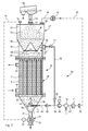
- FIG. 1 shows an embodiment of a device 1 for cooling bulk material.
- the cooling device 1 has a bulk material entry module 2, which is designed as a product buffer container.
- the entry module 2 represents a predrying container.
- a discharge section 3 of the bulk material entry module 2 tapers conically.
- a bulk material distribution cone 4 is arranged centrally and fixed in a manner not shown on a container wall of the bulk material insert module.
- the bulk material distribution cone 4 runs upwards, ie counter to a bulk material conveying direction 5, pointed. In other words, the bulk material distribution cone 4 expands in the conveying direction 5.
- a fan 8 is arranged, which is driven by a motor 9. Instead of the blower 8 and a compressed air generator can be used.
- a sucked from the fan 8 from the environment amount of the drying gas can be set variably via an adjustable throttle (not shown) or via a speed control of the blower 8.
- the throttle is arranged in the gas supply line 7 in the flow path to the blower 8.
- a filter 10 for the input cleaning of the supplied via the gas supply line 7 in the bulk material entry module 2 drying gas is arranged.
- the latter connects the bulk material infeed module 2 with a bulk material heat exchanger module 12 of the cooling device 1.
- a rotary valve 13 as a bulk material metering device and for pressure sealing arranged.
- a cellular wheel 14 of the rotary valve 13 is driven by a motor 15.
- the structure of the bulk material heat exchanger module is known in principle from the DE 10 2004 041 375 A1 and the DE 10 2007 027 967 A1 , Through this leads a plurality of heat exchanger tubes 17 for conveying the bulk material to be cooled in the heat exchanger module 12 through the heat exchanger section 16. In the illustrated embodiment, this technically the done by gravimetric flow of the bulk material through the heat exchanger section 16. Miters in connection standing spaces 18 between the heat exchanger tubes 17 are available with a schematically illustrated inlet port 19 for introducing a cooling medium and with an outlet nozzle 20 also shown schematically for discharging the cooling medium from the intermediate spaces 18 in fluid communication.
- the heat exchanger tubes 17 thus represent heat exchanger elements which are in thermal contact with the cooling medium via the intermediate spaces 18.
- the cooling medium is passed through the heat exchanger section 16 in countercurrent to the bulk material conveying direction 5.
- the heat exchanger module 12 In the conveying direction 5 in front of the heat exchanger section 16, the heat exchanger module 12 has its own bulk material buffer section 21. In these, the conveying line 11 opens. Downstream of the heat exchanger section 16 in the conveying direction 5 is a discharge module of the cooling device 1 in the form of a discharge section 22 of the heat exchanger module 12, which tapers conically in a similar manner to the discharge section 3 of the entry module 2 in the conveying direction 5.
- the buffer section 21, the heat exchanger section 16 and the discharge section 22 are sections of a common module housing 23 of the heat exchanger module 12.
- the discharge section 22 opens another gas supply line 24 for introducing bulk material drying gas in countercurrent to the conveying direction 5 through the heat exchanger module 12.
- the further gas supply line 24 is another blower 25 for Trocknungsgasposed, which is driven by a motor 26 .
- a condensate separator 27 is arranged in the further gas supply line 24.
- a suction cooler 28 designed as a heat exchanger is arranged in the further gas feed line 24. Upstream of the suction cooler 28 is at a suction end of the further gas supply line 24, in turn, a filter 29 for input cleaning of the other gas supply line 24 arranged the heat exchanger module 12 amount of drying gas.
- Also in the gas supply line 24 may be arranged an adjustable throttle, with which the sucked from the fan 25 from the environment amount of the drying gas can be variably specified.
- the discharge section 22 opens into a bulk material discharge line 30.
- a further rotary feeder 31 is arranged as a discharge metering device, the cell wheel 32 is driven by a further motor 33.
- slides or screw conveyors can in principle also be used as metering devices.
- the motors 9, 15, 26, 33 and the suction cooler 28 and a conveyor not shown for the guided through the heat exchanger section 16 cooling medium are controlled by a central control device, not shown.
- the throttles, not shown in the gas supply lines 7, 24 may alternatively also be designed as motor-adjustable valves or flaps, in particular as control valves or control valves, and may then also be controlled by the central control device.
- a treatment method for bulk material runs in the cooling device 1 as follows: First, the bulk material is filled into the entry module 2 or accumulated by slowing down the feeder speed at the rotary valve 31. By means of the passage of the drying gas, the bulk material is dried in countercurrent to the conveying direction 5 by the entry module 2. The drying gas coming from the feed section 6, is initially deflected radially outwards by the bulk material distribution cone 4 (cf., directional arrow 34), so that the bulk material, which flows past the distribution cone 4 in the discharge section 3 of the entry module 2, is uniformly and completely charged with the drying gas. After drying in the passage through the entry module 2, the bulk material is conveyed by means of the rotary valve 13 toward the heat exchanger module 12.
- the bulk material is cooled in the heat exchanger section 16.
- the cooling takes place mainly by contact of the bulk material with the tube walls of the heat exchanger tubes 17, which in turn are cooled by the cooling medium.
- the bulk material is further dried in the heat exchanger module 12 with the aid of the cooled drying gas, which is supplied via the further gas feed line 24, in countercurrent to the conveying direction 5.
- internals can be provided, which bring about a relative movement of the bulk material particles with each other.
- Such internals may be, for example, perforated plates, gratings or other designs designed to effect such rearrangement by relative movement of the bulk material particles with each other.
- fertilizers As bulk material, fertilizers, salts, biomass or sugar can be used.
- These fertilizers may also be coated or it may be added to these fertilizers, a flow aid.
- the bulk material may be in the form of crystals, pellets or prills.
- the bulk material is fed to the entry module 2 with a residual moisture content of not more than 3%.
- the residual moisture of the bulk material provided may alternatively not be greater than 1% or not greater than 0.5%.
- a drying residence time of the bulk material in the infeed module 2 is greater than one minute and may be greater than two minutes, may be greater than three minutes, may be greater than five minutes, may be greater than ten minutes, may be greater than twenty minutes, can be 30 minutes and can be greater than 30 minutes.
- the drying of the bulk material in the entry module 2 before the heat exchange in the heat exchanger module 12 prevents caking of bulk material in the heat exchanger module 12.
- a drying gas air or nitrogen can be used.
- heat exchanger plates may also be arranged in the heat exchanger section 16, as in the example of FIG. 2 of the EP 0 444 338 B1 shown.
- heat exchanger elements can also be used horizontally and / or transversely to the conveying direction 5 through the heat exchanger section 16 extending and traversed by the cooling medium pipes.
- These tubes may have different cross-sectional shapes and, for example, have an oval or quadrangular cross-section.
- FIGS. 1a and 1b show two alternatives of discharge sections 35, 36, which can be used instead of the discharge section 3 in the bulk material entry module 2. Components which correspond to those described above with reference to FIG. 1 have already been explained, bear the same reference numbers and will not be explained again in detail.
- the discharge section 35 after FIG. 1a has a buffer portion 37 of the entry module 2 directly following a first cone portion 38.
- This has a ring-shaped circumferential cone or funnel 39, which tapers in the conveying direction 5 funnel-shaped towards a circular funnel exit 41 for the bulk material.
- a collecting space section 42 Connected to the cone section 38 in the bulk material conveying direction 5 is a collecting space section 42, which is likewise conical in shape.
- the plenum section 42 opens from the side, the gas supply line. 7 one.
- the conically tapered collecting chamber section 42 opens into the bulk material conveying line 11.
- the drying gas from the gas supply line 7 first flows into an outer annular space 40 in the interior of the collecting space subsection 42 and from there in countercurrent to the bulk material conveying direction 5 through the annular funnel exit 41 in the FIG. 1a upward, ie by annular cone and the other cone portion 38 and subsequently by the buffer portion 37 of the entry module. 2
- the discharge section 36 after FIG. 1b is designed as a double cone with two successive cone sections 43, 44.
- the first cone section 43 in the conveying direction 5 tapers towards a funnel outlet 45.
- the latter lies within the downstream second cone section 44, which constitutes a collecting space.
- the second cone section 44 tapers conically towards the bulk material delivery line 11.
- the drying gas flows from the gas supply line 7 first into the second cone section 44, that is, into the collecting space of the embodiment FIG. 1b , Subsequently, the drying gas flows in countercurrent to the bulk material conveying direction 5 through the funnel exit 45 into the cone section 43 and from there into the buffer section 37 of the entry module 2 FIG. 1b ,
- the buffer section 37 can also be a bulk goods storage container, for example a storage silo, which is arranged upstream of the discharge section 3.
- FIG. 2 shows a further embodiment of a cooling device 46.
- a bulk material entry module 47 and the heat exchanger module 12 are sections of a common module housing 48.
- Bulk 49 passes from a screening machine 50 via a downcomer 52 and a bulk material entry port 51 in the bulk material entry module 47th
- the structure of the bulk material entry module 47 corresponds to that of the buffer section 37 with a downstream cone section 38 of the embodiment FIG. 1a ,
- the circular ring-shaped funnel exit 41 of the annular cone or funnel 39 of the cone section 38 of the bulk material introduction module 47 opens directly into the bulk material buffer section 21 of the bulk material heat exchanger module 12.
- This bulk material buffer section 21 of the heat exchanger module 12 opens laterally a gas feed port 55, which in turn communicates with a gas supply line 56 for introducing the drying gas.
- the gas supply line 56 of the embodiment according to FIG. 2 corresponds to the gas supply line 7 of the embodiment according to FIG. 1 ,
- a manually operable manual flap 57 is provided as a throttle unit for setting a quantity of gas in the gas supply line 56.
- an adjustable aperture 58 is arranged for additional specification of the amount of drying gas.
- the aperture 58 may also be used as an alternative to the manual flap 57 for setting the amount of drying gas.
- the buffer portion 21 has at least one height such that an outer region of the heat exchanger module 12 is just filled with bulk material automatically on the angle of repose. In order to ensure this filling of the outer region of the heat exchanger module 12, the overall height of the buffer section 21 is selected 200 mm to 500 mm larger than this minimum height.
- the buffer section 21 is constructed so that the heat exchanger module 12 is accessible from above via the lateral inspection openings (not shown) for cleaning and inspection via the buffer section 21.
- a gas suction nozzle 59 is arranged with downstream suction line 60.
- a suction fan 61 is arranged in the suction line 60.
- a filter may be arranged in the suction line 60 in order to prevent contamination of the suction fan 61.
- a roof-shaped bulk material distribution cone 62 is arranged in the discharge section 22 of the heat exchanger module 12. Directly below the distributor cone 62 opens into the discharge section 22 laterally another gas supply port 63, which communicates with a further gas supply line 64, the function of the further gas supply line 24 in the embodiment according to FIG. 1 equivalent.
- a manually operable hand flap 65 is arranged in the further gas supply line 64. Upstream, on the one hand, the orifice 58 and on the other hand, the hand flap 65, the two supply lines 56 and 64 unite at a distribution point 66. Upstream of the distribution point 66, a main gas supply line 67 is arranged. The two gas supply lines 56, 64 are thus fed by a common gas source.
- a fan 68 is disposed upstream of the distribution point 66, the is driven by a motor 69.
- a condensate separator 70 is disposed in the main gas supply line 67.
- a suction cooler 71 is disposed in the main gas supply pipe 67.
- a filter 72 for cleaning the sucked drying gas is arranged in the region of a suction end of the main gas supply line 67.
- a measuring lance 73 of a filling level transmitter 74 is arranged in the buffer section 37 of the bulk material entry module 47.
- These two components constitute a bulk material level sensor for the buffer section 37.
- the motor 33 of the rotary valve 31 in the bulk material discharge line 30 on the one hand and the fill level transmitter 74 on the other hand are connected to one another via a control loop 75.
- a treatment of the bulk material 49 is carried out with the cooling device 46 as follows:
- the bulk material 49 passes through the screening machine 50 and the bulk material entry port 51 in the bulk material-entry module 47.
- the bulk material 49 then flows through the buffer section 37 and the cone section 38 and through the annular Funnel exit 41 into the bulk material buffer section 21 of the heat exchanger module 12.
- the bulk material is dried by means of the passage of the drying gas through the gas supply line 56.
- the drying gas enters the bulk material buffer section 21 (see directional arrow 76) of the heat exchanger module 12 via the gas feed port 55, which simultaneously constitutes a collecting space for the drying gas.
- the drying gas flows through the funnel exit 41 of the circular, circulating cone 39 of the cone section 38 and further over the buffer section 37.
- the drying gas is conveyed via the gas suction connection 59 and sucked the suction line 60 (see arrows).
- the drying gas can be recycled.
- the suction line 60 is then in fluid communication with the main gas supply line 67.
- a separator cyclone and / or a dust filter for separating dust particles and corresponding cleaning of the drying gas can then be arranged between the gas extraction nozzle 59 and the suction blower 61.
- the thus dried or predried bulk material is then cooled in the heat exchanger module 12 while flowing through the heat exchange tubes 17 of the heat exchanger section 16.
- the bulk material is further dried over the further drying gas, which is supplied via the further gas supply line 64.
- This further drying gas flows into the interior of the discharge section 22 via the gas feed port 63.
- the distributor cone 62 ensures that the bulk material, which is conveyed through the discharge section 22, is evened out and is subjected as homogeneously as possible to the further drying gas (compare directional arrow 78).
- a static sieve may be arranged as an agglomerate catcher in the entry module buffer section 37.
- Such an agglomerate catcher can also be arranged in the buffer section 21.
- the fill level transmitter 74 Via the fill level transmitter 74, the control loop 75 and the motor 33 for the rotary valve 31, it is ensured that the fill level in the entry module buffer section 37 is in the range of a predetermined fill level bandwidth remains.
- a maximum permissible fill level and a minimum permissible fill level can also be interrogated via the fill level transmitter 74. This monitoring of a maximum allowable level and a minimum allowable level can alternatively be done by two separate level indicator instead of Gustandsstransmitters 74.
- FIG. 3 shows a further variant of a bulk material entry module 79, which instead of the bulk material entry module 47 after FIG. 2 can be used.
- a bulk material entry module 79 which instead of the bulk material entry module 47 after FIG. 2 can be used.
- Components which correspond to those already explained above with reference to the figures bear the same reference numerals and will not be discussed again in detail.
- a spreading plate 80 is present at the bulk material injection module 79. This has a diameter which is slightly larger than that of the inlet nozzle 51.
- the spreading plate 80 has an impact wall 81 which extends from a center of the spreading plate 80, starting conically sloping outwards.
- the scattering plate 80 is held in a manner not shown relative to the entry port 51 in position.
- the scattering plate 80 may stand in the operation of the cooling device with the entry module 79 or, as in the FIG. 3 indicated by a directional arrow 82 to one in the FIG. 3 Rotate vertical axis 83 driven by a motor, not shown, which extends through the center of the spreading plate 80.
- a cone section 83 Downstream of the buffer section 37 of the entry module 79 is a cone section 83 with a total of two cones or funnels 84, 85 arranged concentrically in one another in the form of a circle.
- the funnels 84, 85 taper in the conveying direction 5 towards concentric nested, annular circumferential funnel exit 41, 86 (see Fig. 3a ) and terminate in the bulk material buffer section 21 of the heat exchanger module 12.
- Laterally offset to the central bulk material entry port 51 is in a top wall 88 of the module housing 48 of the execution to FIG. 3 a drying gas outlet 89 arranged. This communicates with a suction line 90, whose function of that of the suction line 60 in the execution after FIG. 2 equivalent.
- the suction fan 61 is arranged.
- the bulk material buffer section 21 of the heat exchanger module has 12 thus the function of a collecting space for the drying gas.
- the drying gas leaves the entry module buffer section 37 via the drying gas outlet port 89 and the suction line 90.
- the suction line 90 in turn with the gas supply line 56 or with a main gas supply line in the manner of the main gas Feed line 67 after FIG. 2 in fluid communication.
- the inner annular cone or funnel 86 can be connected to the gas supply port 55 via its own, in the Fig. 3 Be connected supply line not shown. This ensures that the drying gas also flows through the inner annular cone 86.
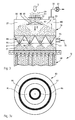
- FIGS. 4 to 6 further embodiments of cone sections are explained, which can be used instead of the cone sections 38 and 83.
- Components which correspond to those already explained above with reference to the figures bear the same reference numerals and will not be discussed again in detail.
- a cone section 91 after the FIGS. 4 and 5 has at least two slot funnels 92, 93 with slot-shaped or longitudinal outlet openings 94, which in the FIG. 5 are shown in a plan. These outlet openings 94 serve on the one hand for the passage of the bulk material in the conveying direction 5 and on the other hand for the passage of the drying gas in the opposite direction.
- the function of the cone section 91 otherwise corresponds to the function of the cone section 38 FIG. 2 ,
- a cone section 95 after FIG. 6 has an outer, circular peripheral cone ring 96, which in the conveying direction 5, in the FIG. 6 extends vertically from above through the plane of the drawing, inwardly towards a rectangular circumferential outlet opening 97 drops.
- the exit opening 97 bounded inwardly a central, pyramid-shaped counter-cone 98, which is in the opposite direction to the conveying direction 5 to the center tapered towards whose guide walls 99 so also fall to the exit opening 97 out.
- the configuration of the cone section 95 according to FIG. 6 favors a well-distributed transfer of the bulk material from the cone section 95 in the downstream buffer section 21 and thus leads to a good drying performance by the in the opposite direction to the conveying direction 5 through the outlet opening 97 flowing drying gas.
- a circular exit opening may also be present.
- the cone ring 96 and the counter cone 98 can also be designed as rotationally symmetrical cones.
- the amounts of gas in the various supply lines can also be specified by means of a control circuit, not shown, depending on the drying capacity to be achieved. This can be done, for example, depending on the degree of moisture of the supplied bulk material and / or depending on the supplied bulk flow, the bulk material temperature, the type of bulk material or other parameters.
- FIG. 3 can be a view of the bulk material during drying accomplish.
- FIG. 3 are separated from the other bulk material 49 to be separated during the viewing dust particles with 100. These dust particles are removed via the suction line 90 and can later be separated from the drying gas via a separator cyclone and / or a filter.
- an absorption dryer For drying the drying gas prior to its introduction into the entry module and / or the heat exchanger module, an absorption dryer can be used.
Landscapes
- Engineering & Computer Science (AREA)
- Mechanical Engineering (AREA)
- General Engineering & Computer Science (AREA)
- Physics & Mathematics (AREA)
- Thermal Sciences (AREA)
- Drying Of Solid Materials (AREA)
Abstract
Description
- Die Erfindung betrifft eine Vorrichtung zum Kühlen von Schüttgut nach dem Oberbegriff des Anspruchs 1. Ferner betrifft die Erfindung ein Verfahren zum Behandeln von Schüttgut.
- Vorrichtungen der eingangs genannten Art sind bekannt aus der
DE 10 2007 027 967 A1 , derDE 10 2004 041 375 A1 , derEP 0 444 338 B1 , derDE 196 43 699 C1 , derDE 36 39 046 A1 , derDE 31 31 425 A1 , derAT 205 008 B CH 296 419 A - Es ist eine Aufgabe der vorliegenden Erfindung, eine Kühlvorrichtung der eingangs genannten Art derart weiterzubilden, dass ein unerwünschtes Anbacken des Schüttguts insbesondere an den Wärmetauscherelementen vermindert oder ganz vermieden ist.
- Diese Aufgabe ist erfindungsgemäß gelöst durch eine Vorrichtung mit den im Anspruch 1 angegebenen Merkmalen.
- Erfindungsgemäß wurde erkannt, dass der Grund für das Anbacken darin liegt, dass das Schüttgut mit einer Restfeuchte oberhalb eines Feuchte-Vorgabewerts im Kontakt mit dem Wärmetauscherelementen zu einer Agglomeration und damit zu einem Anbacken neigt. Ein Absolutwert für den Feuchte-Vorgabewert, unterhalb von dem eine Agglomerationsneigung ausreichend gering ist, ist abhängig vom verwendeten Schüttgut, abhängig von der Partikelform des Schüttguts, abhängig von der Partikelgrößenverteilung des Schüttguts sowie abhängig von dem Verfahren zur Herstellung des Schüttguts. Dabei gilt, dass eine große Oberfläche der Schüttgutpartikel ein Austreten von Feuchtigkeit aus dem Partikelinneren begünstigt. Es hat sich herausgestellt, dass eine Trocknung im Schüttgut-Eintragsmodul, die zu einer Verringerung der Feuchte beispielsweise bei 150° C um mehr als 100 ppm führt, das unerwünschte Anbacken des Schüttguts an den Wärmetauscherelementen bereits stark reduziert. Die Feuchte des Schüttguts kann bei der Vortrocknung im Schüttgut-Eintragsmodul um mehr als 300 ppm, um mehr als 500 ppm oder auch um mehr als 1000 ppm, jeweils gemessen bei 150° C, verringert werden. Durch den Einsatz der erfindungsgemäßen Gas-Zuführleitung zur Einleitung eines Trocknungsgases lässt sich eine Vortrocknung des Schüttguts im Schüttgut-Eintragsmodul, also im Förderweg des Schüttguts vor dem Schüttgut-Wärmetauschermodul, erreichen, sodass eine Restfeuchte des Schüttguts unterhalb des Vorgabewerts resultiert, was wiederum dazu führt, dass das Schüttgut an den Wärmetauschelementen nicht oder kaum anbackt. Dies erhöht die Standzeit der Kühlvorrichtung im Vergleich zum Stand der Technik, insbesondere die Reinigungs-Intervalle, nach deren Ablauf die nächste Reinigung der Kühlvorrichtung fällig ist. Durch die erfindungsgemäße Vortrocknung im Schüttgut-Eintragsmodul kann ein Ausströmen von Feuchtigkeit aus den einzelnen Schüttgut-Partikeln so lange unterbunden werden, wie das Schüttgut für einen Transport durch den Schüttgut-Wärmetauscher, insbesondere für ein gravimetrisches Durchfließen, benötigt. Als Schüttgut können Düngemittel, Salze, Zucker, Biomasse oder andere Schüttgutmaterialien zum Einsatz kommen. Als Trocknungsgas kann Luft oder Stickstoff oder auch ein anderes Gas zum Einsatz kommen. Insbesondere dann, wenn nicht Luft, sondern ein anderes Trocknungsgas zum Einsatz kommt, kann das Trocknungsgas in einem Kreislaufsystem der Kühlvorrichtung geführt sein. Das Trocknungsgas kann, falls Luft eingesetzt wird, aus der Umgebung angesaugt werden. Das Trocknungsgas kann auch von einer Gasquelle bereitgestellt werden. Die Gas-Zuführleitung kann gleichzeitig einen Schüttgut-Zuführstutzen darstellen. In diesem Fall ist es möglich, ein Schüttgut-Eintragsmodul ohne größere bauliche Veränderungen innerhalb der erfindungsgemäßen Kühlvorrichtung einzusetzen. Die Kühlvorrichtung kann eine Absaugeinrichtung für das Trocknungsgas aufweisen, die eine nachgeordnete Entstaubungseinrichtung aufweisen kann. Eine derartige Entstaubung kann durch einen Zyklon und/oder durch einen Filter gewährleistet werden. Das Schüttgut-Eintragsmodul kann gleichzeitig als Sichtereinheit der Kühlvorrichtung eingesetzt sein. In diesem Fall kann das Trocknungsgas gleichzeitig die Funktion eines Sichtgases übernehmen. Auf diese Weise lassen sich beispielsweise Staubpartikel vom Schüttgut innerhalb der Kühlvorrichtung abtrennen. Diese Abtrennung vergrößert ebenfalls die Standzeit der Kühlvorrichtung und die Reinigungsintervalle, da zur unerwünschten Ablagerung bzw. zum unerwünschten Anbacken neigende Staubanteile aus dem Inneren der Kühlvorrichtung entfernt werden. Zur Vergleichmäßigung des Eintrages des Schüttgutes in das Schüttgut-Eintragsmodul kann eine Streueinrichtung zur Ablenkung der Schüttgutförderung eingesetzt sein. Die Wärmetauscherelemente können als Wärmetauscherplatten oder als Wärmetauscherrohre ausgebildet sein. Die Wärmetauscherrohre können längs der Schüttgut-Förderrichtung angeordnet sein und beispielsweise das Schüttgut führen. Alternativ ist es möglich, die Wärmetauscherelemente quer oder senkrecht zur Schüttgut-Förderrichtung im Wärmetauschermodul anzuordnen. In diesem Fall führen die Wärmetauscherelemente das Kühlmedium. Die Ausführung des Schüttgut-Eintragsmoduls erfolgt so, dass die Verweilzeit des Schüttguts im Eintragsmodul größer ist als 1 min. Dies führt zu einer effektiven Trocknung des Schüttgutes. Es ist nicht erforderlich, dass das der Kühlvorrichtung zugeführte Schüttgut bereits vorgetrocknet ist. Das Schüttgut kann vor dem Trocknen mit einer Restfeuchte bereitgestellt werden, die beispielsweise 3 % beträgt. Die Restfeuchte ist dabei definiert als das Verhältnis des Gewichts des Feuchtigkeitsanteils zum Gewicht des Schüttguts. Die Trocknungs- bzw. Verweilzeit kann größer sein als 2 min, kann größer sein als 3 min, kann größer sein als 5 min, kann größer sein als 10 min, kann größer sein als 20 min, kann 30 min betragen und kann auch größer sein als 30 min. Verweilzeiten größer als 1 min können durch die gezielte Erzeugung eines Produktstaus im Schüttgut-Eintragsmodul erzielt werden. Das Schüttgut-Eintragsmodul ist so ausgestaltet, dass im Wesentlichen eine Festbett-Durchströmung des Trocknungsgases durch das im Eintragsmodul vorliegende Schüttgut erreicht wird. Die Trocknung findet dann durch einen Diffusionsprozess statt, d. h. die Feuchtigkeit verdunstet bzw. verdampft an der Oberfläche der Schüttgutpartikel und wird von dem Trocknungsgas aufgenommen.
- Eine Ausgestaltung nach Anspruch 2, bei der das Schüttgut-Eintragsmodul als Produktpuffer, also als Schüttgut-Puffer ausgebildet ist, stellt einen gleichmäßigen Durchsatz des Wärmetauschermoduls bei gleich bleibender Verweilzeit im Wärmetauschermodul sicher. Dies begünstigt einen gleichmäßigen Kühleffekt.
- Entsprechende Vorteile lassen sich mit einem Schüttgut-Füllstandssensor nach Anspruch 3 realisieren. Ein unerwünschtes Überfüllen oder auch ein unerwünschtes Entleeren des Schüttgut-Eintragsmoduls kann so verhindert sein.
- Eine separate Ausführung nach Anspruch 4 kann mit einer Dosiereinrichtung in der verbindenden Förderleitung ausgestattet sein. Bei der Dosiereinrichtung kann es sich um eine Zellenradschleuse handeln. Die Dosiereinrichtung kann, soweit ein Schüttgut-Füllstandssensor vorgesehen ist, mit diesem in Signalverbindung stehen. Auf diese Weise ist ein geregelter Durchsatz des Schüttgut-Eintragsmoduls möglich. Entsprechend kann auch eine Dosiereinrichtung in Förderrichtung nach dem Wärmetauschermodul mit dem Schüttgut-Füllstandssensor in Signalverbindung stehen, sodass ein geregelter Durchsatz der gesamten Kühlvorrichtung realisiert sein kann.
- Ein Austragsabschnitt des Schüttgut-Eintragsmoduls kann als einfacher Konus, als Doppelkonus oder als Mehrfachkonus mit integriertem Sammelraum ausgeführt sein. Ein Austragsabschnitt des Schüttgut-Eintragsmoduls kann auch als Konus bzw. Trichter mit ringförmig umlaufendem Trichterausgang ausgeführt sein. Bei der Ausführung als Doppel- oder Mehrfachkonus können mehrere ineinander liegend angeordnete Trichter vorhanden sein, sodass sich mehrere ineinander liegende ringförmige, insbesondere kreisringförmige Auslauf- bzw. Ausgangsöffnungen für das Schüttgut ergeben. Bei der Ausführung mit Sammelraum kann in diesen ein einziger Trichter oder eine Mehrzahl von Trichtern einmünden.
- Eine Ausgestaltung nach Anspruch 5 ermöglicht eine kompakte Anordnung der Kühlvorrichtung in einer Anlagenumgebung.
- Eine Ausführung nach Anspruch 6 ist besonders kompakt. Das Trocknen und das Kühlen können in ein und demselben Modulgehäuse stattfinden. Auch das Schüttgut-Austragsmodul kann als Abschnitt des gemeinsamen Modulgehäuses der Kühlvorrichtung ausgeführt sein. In der Regel ist das Schüttgut-Austragsmodul als Abschnitt des Gehäuses des Wärmetauschermoduls ausgeführt.
- Ein Konusabschnitt nach Anspruch 7 ermöglicht eine gute Verteilung des Trockungsgases und des Schüttgutes über den Querschnitt des Schüttgut-Eintragsmoduls und entsprechend eine effiziente Trocknung des Schüttguts. Der obere Bereich des Wärmetauschermoduls kann bei einer solchen Konstruktion gut für eine Reinigung von der Seite her über Inspektionsöffnungen am Umfang des Schüttgut-Eintragsmoduls bzw. des Wärmetauschermoduls zugänglich sein. Die Trichter können als runde oder auch als rechteckige Konen mit runden oder rechteckigen Ausgabeöffnungen ausgeführt sein. Mehrere derartiger Konen können ineinander liegend, insbesondere konzentrisch ineinander liegend, angeordnet sein, sodass sich ringförmig umlaufende Ausgabeöffnungen für das Schüttgut ergeben. Bei rechteckig ausgeführter Gehäuseform des Schüttgut-Eintragsmoduls und/oder des Wärmetauschermoduls können auch nebeneinander angeordnete Trichter mit runden Ausgabeöffnungen oder auch rechteckige Konen mit runden oder rechteckigen Ausgabeöffnungen für das Schüttgut eingesetzt sein. Das Gehäuse des Schüttgut-Eintragsmoduls kann einen runden oder auch einen rechteckigen Querschnitt aufweisen. Der mindestens eine Trichter kann eine schlitzförmige Ausgabeöffnung aufweisen. Der mindestens eine Trichter kann eine ringförmig umlaufende Ausgabeöffnung aufweisen, die rund oder rechteckig gestaltet sein kann. Hierbei kann insbesondere innerhalb des Rings ein für Schüttgut undurchlässiges Zentrum vorgesehen sein. Diese Gestaltungen ermöglichen eine Verteilung des Schüttguts innerhalb des Schüttgut-Eintragsmoduls, die an jeweils gestellte Anforderungen angepasst sein kann. Soweit mehrere Trichter in dem Konusabschnitt vorhanden sind, können zwischen den Trichtern Verbindungsleitungen für das Trocknungsgas vorhanden sein, um die das Schüttgut herumfließen kann. Eine derartige Verbindungsleitung kann als dreiecksförmiges Dach ausgeführt sein.
- Eine Trichteranordnung nach Anspruch 8 ermöglicht einen Konusabschnitt mit vorteilhaft niedriger Bauhöhe bei vorgegebener Verteilungsleistung. Eine weitere Gas-Zuführleitung nach Anspruch 9 ermöglicht eine weitergehende Trocknung des Schüttguts beim Durchleiten von diesem durch das Wärmetauschermodul. Die weitere Gas-Zuführleitung kann mit einer Kühleinheit für das Trocknungsgas kommunizieren. Dies erhöht die Trocknungsleistung des Trocknungsgases, sodass dieses auch dann noch trocknend wirkt, wenn das Schüttgut im Wärmetauschermodul bereits abgekühlt ist. Zudem kann die Kühleinheit verhindern, dass das abgekühlte Schüttgut unerwünscht durch das Trocknungsgas aufgewärmt wird.
- Eine gemeinsame Gasquelle nach Anspruch 10 führt zu einer effizienten Trocknungsgasversorgung.
- Mindestens eine Drosseleinheit nach Anspruch 11 ermöglicht eine geführte Gasmengenvorgabe in der mindestens einen Gas-Zuführleitung. Bei mehreren Gas-Zuführleitungen kann mit Hilfe der mindestens einen Drosseleinheit oder mit Hilfe einer Mehrzahl von Drosseleinheiten auch eine Verteilung des Trocknungsgases auf die verschiedenen Gas-Zuführleitungen vorgegeben werden.
- Die eingangs genannte Aufgabe ist zudem gelöst durch ein Verfahren nach Anspruch 12.
- Die Vorteile dieses Verfahrens entsprechen denen, die vorstehend unter Bezugnahme auf die erfindungsgemäße Kühlvorrichtung bereits erläutert wurden. Es kann vor dem Trocknen Schüttgut mit einer Restfeuchte bereitgestellt werden, die nicht größer ist als 3 %. Die Restfeuchte des Schüttguts vor dem Trocknen kann maximal 1 % oder auch maximal 0,5 % betragen. Eine Trocknungszeit bzw. eine Verweilzeit des Schüttguts in einem Trocknungsmodul kann größer sein als 2 min, kann größer sein als 3 min, kann größer sein als 5 min, kann größer sein als 10 min, kann größer sein als 20 min, kann 30 min betragen und kann auch größer sein als 30 min. Die Trocknungszeit ist dabei diejenige Zeit, in der das Trocknungsgas auf das Schüttgut einwirkt, das Schüttgut also mit dem Trocknungsgas beaufschlagt ist. Das Verfahren kann unter Einsatz der erfindungsgemäßen Kühlvorrichtung eingesetzt werden. In diesem Fall stellt das Schüttgut-Eintragsmodul der erfindungsgemäßen Kühlvorrichtung das Trocknungsmodul dar. Die Verweilzeit kann solange sein, dass die Feuchte des Schüttguts beim Trocknen um mehr als 300 ppm, um mehr als 500 ppm oder auch um mehr als 1.000 ppm verringert wird. Das Schüttgut kann während des Trocknens temperiert vorliegen. Die Trocknungstemperatur kann im Bereich zwischen 50°C und 180°C, kann im Bereich zwischen 80°C und 160°C und kann insbesondere im Bereich zwischen 80°C und 130°C, z. B. bei 100°C, liegen. Die Trocknung kann durch einen Diffusionsprozess stattfinden, bei dem das Schüttgut im Bereich der Partikeloberflächen getrocknet wird.
- Eine Gegenstromführung nach Anspruch 13 führt zu einer besonders effizienten Trocknung des Schüttguts.
- Durch ein Verfahren nach Anspruch 14 lässt sich die Trocknungsleistung weiterhin erhöhen. Bevorzugt wird während des Kühlens gekühltes Trocknungsgas eingesetzt.
- Ein Sichten des Schüttguts nach Anspruch 15 führt zu einem behandelten Schüttgut als Verfahrensergebnis mit einer vorgegebenen Korngrößenverteilung ohne Fraktion mit unerwünscht kleinen Schüttgut- oder Staubpartikeln. Zudem kann ein Schüttgutsichten zu einer Verlängerung der Standzeit führen, wie vorstehend im Zusammenhang mit der Vorrichtung bereits erläutert wurde.
- Ausführungsbeispiele der Erfindung werden nachfolgend anhand der Zeichnung näher erläutert. In dieser zeigen:
- Figur 1
- schematisch in einer Übersicht eine Vorrichtung zum Kühlen von Schüttgut, wobei ein Schüttgut-Eintragsmodul und ein Schüttgut-Wärmetauschermodul als separate Einrichtungen ausgeführt sind, die über eine Förderleitung miteinander ver- bunden sind;
- Figur 1a
- einen Austragsabschnitt des Eintragsmoduls, der alternativ zu einem in der
Figur 1 dargestellten Austragsabschnitt zum Einsatz kommen kann; - Figur 1b
- einen Austragsabschnitt des Eintragsmoduls, der alternativ zu dem in der
Figur 1 dargestellten Austragsabschnitt zum Ein- satz kommen kann; - Figur 2
- eine weitere Ausführung einer Vorrichtung zum Kühlen von Schüttgut, wobei ein Schüttgut-Eintragsmodul und ein Schüttgut-Wärmetauschermodul als Abschnitte eines gemein- samen Modulgehäuses der Kühlvorrichtung ausgeführt sind, wobei das Schüttgut-Eintragsmodul, das Schüttgut- Wärmetauschermodul sowie ein Schüttgut-Austragsmodul schematisch in einem Längsschnitt dargestellt sind;
- Figur 3
- eine weitere Ausführung eines Schüttgut-Eintragsmoduls für die Ausgestaltung nach
Figur 2 ; - Fig. 3a
- eine Aufsicht auf einen Konusabschnitt des Schüttgut- Eintragsmoduls nach
Fig. 3 ; - Figur 4
- schematisch einen Längsschnitt durch einen Konusabschnitt eines Schüttgut-Eintragsmoduls nach Art desjenigen der Fi- gur 2;
- Figur 5
- eine Aufsicht auf den Konusabschnitt gemäß Blickrichtung 1 in
Figur 4 ; und - Figur 6
- in einer zu
Figur 5 ähnlichen Darstellung eine Aufsicht auf eine weitere Ausführung eines Konusabschnittes für eine wei- tere Variante eines Schüttgut-Eintragsmoduls. -
Figur 1 zeigt eine Ausführung einer Vorrichtung 1 zum Kühlen von Schüttgut. Die Kühlvorrichtung 1 hat ein Schüttgut-Eintragsmodul 2, das als Produkt-Pufferbehälter ausgeführt ist. Das Eintragsmodul 2 stellt einen Vortrocknungsbehälter dar. Ein Austragsabschnitt 3 des Schüttgut-Eintragsmoduls 2 verjüngt sich konusförmig. Im Austragsabschnitt 3 ist ein Schüttgut-Verteilerkonus 4 zentral angeordnet und in nicht dargestellter Weise an einer Behälterwand des Schüttgut-Einsatzmoduls festgelegt. Der Schüttgut-Verteilerkonus 4 läuft nach oben, also entgegen einer Schüttgut-Förderrichtung 5, spitz zu. Mit anderen Worten erweitert sich der Schüttgut-Verteilerkonus 4 in der Förderrichtung 5. In der Förderrichtung 5 direkt unterhalb des Schüttgut-Verteilerkonus 4 endet ein vertikal verlaufender Zuführabschnitt 6 einer ansonsten horizontal verlaufenden Gas-Zuführleitung 7 zur Einleitung eines Trocknungsgases für das in das Schüttgut-Eintragsmodul geförderte Schüttgut. In der Gas-Zuführleitung 7 ist ein Gebläse 8 angeordnet, das von einem Motor 9 angetrieben ist. Anstelle des Gebläses 8 kann auch ein Drucklufterzeuger zum Einsatz kommen. Eine vom Gebläse 8 aus der Umgebung angesaugte Menge des Trocknungsgases kann über eine verstellbare Drossel (nicht dargestellt) oder über eine Drehzahlregelung des Gebläses 8 variabel vorgegeben werden. Die Drossel ist in der Gas-Zuführleitung 7 im Strömungsweg nach dem Gebläse 8 angeordnet. An einem Ansaugende der Gas-Zuführleitung 7 ist ein Filter 10 zur Eingangs-Reinigung des über das Gas-Zuführleitung 7 im Schüttgut-Eintragsmodul 2 zugeführten Trocknungsgases angeordnet. - Der Austragsabschnitt 3 des Schüttgut-Eintragsmoduls 2 mündet in eine Schüttgut-Förderleitung 11. Letztere verbindet das Schüttgut-Eintragsmodul 2 mit einem Schüttgut-Wärmetauschermodul 12 der Kühlvorrichtung 1. In der Schüttgut-Förderleitung 11 ist eine Zellenradschleuse 13 als Schüttgut-Dosiereinrichtung und zur Druckabdichtung angeordnet. Ein Zellenrad 14 der Zellenradschleuse 13 wird von einem Motor 15 angetrieben.
- Der Aufbau des Schüttgut-Wärmetauschermoduls ist vom Prinzip her bekannt aus der
DE 10 2004 041 375 A1 und derDE 10 2007 027 967 A1 . Das Wärmetauschermodul 12 hat einen Wärmetauscherabschnitt 16. Durch diesen führt eine Mehrzahl von Wärmetauscherrohren 17 zur Durchförderung des im Wärmetauschermodul 12 zu kühlenden Schüttguts durch den Wärmetauscherabschnitt 16. Bei der dargestellten Ausführung erfolgt diese Durchförderung durch gravimetrischen Durchfluss des Schüttguts durch den Wärmetauscherabschnitt 16. Miteinander in Verbindung stehende Zwischenräume 18 zwischen den Wärmetauscherrohren 17 stehen mit einem schematisch dargestellten Einlassstutzen 19 zum Einleiten eines Kühlmediums und mit einem ebenfalls schematisch dargestellten Auslassstutzen 20 zum Ausleiten des Kühlmediums aus den Zwischenräumen 18 in Fluidverbindung. Die Wärmetauscherrohre 17 stellen also Wärmetauscherelemente dar, die über die Zwischenräume 18 in thermischem Kontakt mit dem Kühlmedium stehen. Das Kühlmedium wird durch den Wärmetauscherabschnitt 16 im Gegenstrom zur Schüttgut-Förderrichtung 5 geleitet. - In der Förderrichtung 5 vor dem Wärmetauscherabschnitt 16 hat das Wärmetauschermodul 12 einen eigenen Schüttgut-Pufferabschnitt 21. In diesen mündet die Förderleitung 11 ein. Dem Wärmetauscherabschnitt 16 in der Förderrichtung 5 nachgeordnet ist ein Austragsmodul der Kühlvorrichtung 1 in Form eines Austragsabschnitts 22 des Wärmetauschermoduls 12, der vergleichbar zum Austragsabschnitt 3 des Eintragsmoduls 2 in der Förderrichtung 5 konisch sich verjüngend verläuft. Der Pufferabschnitt 21, der Wärmetauscherabschnitt 16 und der Austragsabschnitt 22 sind Abschnitte eines gemeinsamen Modulgehäuses 23 des Wärmetauschermoduls 12.
- In den Austragsabschnitt 22 mündet eine weitere Gas-Zuführleitung 24 zur Einleitung von Schüttgut-Trocknungsgas im Gegenstrom zur Förderrichtung 5 durch das Wärmetauschermodul 12. In der weiteren Gas-Zuführleitung 24 angeordnet ist ein weiteres Gebläse 25 zur Trocknungsgasförderung, das von einem Motor 26 angetrieben ist. Stromaufwärts des Gebläses 25 ist in der weiteren Gas-Zuführleitung 24 ein Kondensatabscheider 27 angeordnet. Wiederum stromaufwärts des Kondensatabscheiders 27 ist in der weiteren Gas-Zuführleitung 24 ein als Wärmetauscher ausgeführter Ansaugkühler 28 angeordnet. Stromaufwärts des Ansaugkühlers 28 ist an einem Ansaugende der weiteren Gas-Zuführleitung 24 wiederum ein Filter 29 zur Eingangs-Reinigung der über die weitere Gas-Zuführleitung 24 dem Wärmetauschermodul 12 zugeführten Trocknungsgasmenge angeordnet. Auch in der Gas-Zuführleitung 24 kann eine verstellbare Drossel angeordnet sein, mit der die vom Gebläse 25 aus der Umgebung angesaugte Menge des Trocknungsgases variabel vorgegeben werden kann.
- Der Austragsabschnitt 22 mündet in eine Schüttgut-Austragsleitung 30. In dieser ist als Austrags-Dosiereinrichtung eine weitere Zellenradschleuse 31 angeordnet, deren Zellenrad 32 von einem weiteren Motor 33 angetrieben ist.
- Anstelle der Zellenradschleusen 13, 31 können prinzipiell auch Schieber oder Förderschnecken als Dosiereinrichtungen zum Einsatz kommen.
- Die Motoren 9, 15, 26, 33 und der Ansaugkühler 28 sowie eine nicht näher dargestellte Fördereinrichtung für das durch den Wärmetauscherabschnitt 16 geleitete Kühlmedium werden von einer nicht dargestellten zentralen Steuereinrichtung gesteuert. Die nicht dargestellten Drosseln in den Gas-Zuführleitungen 7, 24 können alternativ ebenfalls als motorisch verstellbare Ventile oder Klappen, insbesondere als Regelventile oder Regelklappen, ausgeführt sein und können dann ebenfalls von der zentralen Steuereinrichtung gesteuert sein.
- Ein Behandlungsverfahren für Schüttgut läuft bei der Kühlvorrichtung 1 folgendermaßen ab: Zunächst wird das Schüttgut in das Eintragsmodul 2 eingefüllt bzw. durch Verlangsamung der Zellenrad-Drehzahl an der Zellenradschleuse 31 angestaut. Mittels der Durchleitung des Trocknungsgases wird das Schüttgut im Gegenstrom zur Förderrichtung 5 durch das Eintragsmodul 2 getrocknet. Das Trocknungsgas, das aus dem Zuführabschnitt 6 austritt, wird vom Schüttgut-Verteilerkonus 4 zunächst radial nach außen abgelenkt (vgl. Richtungspfeil 34), sodass das Schüttgut, das im Austragsabschnitt 3 des Eintragsmoduls 2 am Verteilerkonus 4 vorbeifließt, gleichmäßig und vollständig mit dem Trocknungsgas beaufschlagt wird. Nach dem Trocknen bei der Durchleitung durch das Eintragsmodul 2 wird das Schüttgut mit Hilfe der Zellenradschleuse 13 hin zum Wärmetauschermodul 12 gefördert. Dort wird das Schüttgut im Wärmetauscherabschnitt 16 abgekühlt. Das Kühlen erfolgt dabei hauptsächlich durch Kontakt des Schüttgutes mit den Rohrwänden der Wärmetauscherrohre 17, die wiederum vom Kühlmedium gekühlt sind. Gleichzeitig wird das Schüttgut im Wärmetauschermodul 12 mit Hilfe des gekühlten Trocknungsgases, das über die weitere Gas-Zuführleitung 24 zugeführt wird, im Gegenstrom zur Förderrichtung 5 weiter getrocknet.
- In den verschiedenen Schüttgut-Pufferabschnitten können Einbauten vorgesehen sein, die eine Relativbewegung der Schüttgutpartikel untereinander herbeiführen. Derartige Einbauten können zum Beispiel Lochbleche, Gitterroste oder anders gestaltete Konstruktionen sein, die eine solche Umlagerung durch Relativbewegung der Schüttgutpartikel untereinander bewirken.
- Als Schüttgut können Düngemittel, Salze, Biomasse oder Zucker zum Einsatz kommen.
- Als Düngemittel können insbesondere zum Einsatz kommen:
- ASS-Ammonium-Sulphat-Salpeter
- Harnstoff (UREA) und harnstoffbasierte Düngemittel
- Düngemittel, die auf Ammonium-Salzen beruhen, insbesondere AN (Ammonium-Nitrat)-Dünger und AS (Ammoniumsulfat)-Dünger
- NPK (Stickstoff Phosphor Kalium)-Dünger oder NP (Stickstoff Phosphor)-Dünger
- CAN-Dünger (Calzium-Ammonium-Nitrat)
- Dünger auf Phosphatbasis
- SSP (Single Super Phosphat)
- MAP (Monoammonium Phosphat)
- DAP (Diammonium Phosphat)
- TSP (Triple Super Phosphat)
- Pottasche und Gemische derselben
- Gemische aus den oben genannten Düngemitteln
- organischer Dünger
- Diese Düngemittel können auch beschichtet sein bzw. es kann diesen Düngemitteln ein Fließhilfsmittel zugegeben sein.
- Das Schüttgut kann in Form von Kristallen, Pellets oder Prills vorliegen.
- Das Schüttgut wird dem Eintragsmodul 2 mit einer Restfeuchte zugeführt, die nicht größer ist als 3 %. Die Restfeuchte des bereitgestellten Schüttguts kann alternativ nicht größer sein als 1 % oder auch nicht größer sein als 0,5 %. Eine Trocknungs-Verweilzeit des Schüttguts im Eintragsmodul 2 ist größer als eine Minute und kann größer sein als zwei Minuten, kann größer sein als drei Minuten, kann größer sein als fünf Minuten, kann größer sein als 10 Minuten, kann größer sein als 20 Minuten, kann 30 Minuten betragen und kann auch größer sein als 30 Minuten.
- Die Trocknung des Schüttgutes im Eintragsmodul 2 vor dem Wärmetauschen im Wärmetauschermodul 12 verhindert ein Anbacken von Schüttgut im Wärmetauschermodul 12. Als Trocknungsgas kann Luft oder auch Stickstoff zum Einsatz kommen.
- Alternativ zu den Wärmetauscherrohren 17 können im Wärmetauscherabschnitt 16 auch Wärmetauscherplatten angeordnet sein, wie beispielsweise in der
Figur 2 derEP 0 444 338 B1 dargestellt. Als Wärmetauscherelemente können auch horizontal und/oder quer zur Förderrichtung 5 durch den Wärmetauscherabschnitt 16 verlaufende und vom Kühlmedium durchströmte Rohre eingesetzt sein. Diese Rohre können unterschiedliche Querschnittsformen haben und beispielsweise einen ovalen oder viereckigen Querschnitt haben. -
Figuren 1a und 1b zeigen zwei Alternativen von Austragsabschnitten 35, 36, die anstelle des Austragsabschnitts 3 beim Schüttgut-Eintragsmodul 2 zum Einsatz kommen können. Komponenten, die denjenigen entsprechen, die vorstehend unter Bezugnahme auf dieFigur 1 bereits erläutert wurden, tragen die gleichen Bezugsziffern und werden nicht nochmals im Einzelnen erläutert. - Der Austragsabschnitt 35 nach
Figur 1a hat einem Pufferabschnitt 37 des Eintragsmoduls 2 direkt nachfolgend zunächst einen Konus-Teilabschnitt 38. Dieser hat einen ringförmig umlaufenden Konus bzw. Trichter 39, der in der Förderrichtung 5 sich trichterförmig hin zu einem kreisförmigen Trichterausgang 41 für das Schüttgut verjüngt. An den Konus-Teilabschnitt 38 schließt sich in der Schüttgutförderrichtung 5 an einen Sammelraum-Teilabschnitt 42, der ebenfalls konusförmig gestaltet ist. In den Sammelraum-Teilabschnitt 42 mündet von der Seite her die Gas-Zuführleitung 7 ein. Der sich konisch verjüngende Sammelraum-Teilabschnitt 42 mündet in die Schüttgut-Förderleitung 11. - Beim Einsatz des Austragsabschnitts 35 nach
Figur 1a strömt das Trocknungsgas aus der Gas-Zuführleitung 7 zunächst in einen äußeren Ringraum 40 im Inneren des Sammelraum-Teilabschnitts 42 und von dort im Gegenstrom zur Schüttgut-Förderrichtung 5 durch den kreisringförmigen Trichterausgang 41 in derFigur 1a nach oben, also durch ringförmigen Konus und den weiteren Konus-Teilabschnitt 38 und nachfolgend durch den Pufferabschnitt 37 des Eintragsmoduls 2. - Der Austragsabschnitt 36 nach
Figur 1b ist als Doppelkonus mit zwei hintereinander liegenden Konus-Teilabschnitten 43, 44 ausgeführt. Der in der Förderrichtung 5 erste Konus-Teilabschnitt 43 verjüngt sich hin zu einem Trichterausgang 45. Letzterer liegt innerhalb des nachgeordneten zweiten Konus-Teilabschnitts 44, der einen Sammelraum darstellt. Der zweite Konus-Teilabschnitt 44 verjüngt sich konusförmig hin zur Schüttgut-Förderleitung 11. - Beim Trocknen des Schüttguts strömt das Trocknungsgas von der Gas-Zuführleitung 7 zunächst in den zweiten Konus-Teilabschnitt 44, also in den Sammelraum der Ausführung nach
Figur 1b . Anschließend strömt das Trocknungsgas im Gegenstrom zur Schüttgut-Förderrichtung 5 durch den Trichterausgang 45 in den Konus-Teilabschnitt 43 und von diesem in den Pufferabschnitt 37 des Eintragsmoduls 2 nachFigur 1b . - Der Pufferabschnitt 37 kann auch einen dem Austragsabschnitt 3 vorgeordneten Schüttgut-Lagerbehälter, beispielsweise ein Lagersilo, darstellen.
Figur 2 zeigt eine weitere Ausführung einer Kühlvorrichtung 46. Komponenten, die denjenigen entsprechen, die vorstehend unter Bezugnahme auf die Figuren bereits erläutert wurden, tragen die gleichen Bezugsziffern und werden nicht nochmals im Einzelnen diskutiert. - Bei der Kühlvorrichtung 46 sind ein Schüttgut-Eintragsmodul 47 und das Wärmetauschermodul 12 Abschnitte eines gemeinsamen Modulgehäuses 48.
- Schüttgut 49 gelangt von einer Siebmaschine 50 über eine Fallleitung 52 und einen Schüttgut-Eintragsstutzen 51 in das Schüttgut-Eintragsmodul 47.
- Der Aufbau des Schüttgut-Eintragsmoduls 47 entspricht demjenigen des Pufferabschnitts 37 mit nachgeordnetem Konus-Teilabschnitt 38 der Ausgestaltung nach
Figur 1a . Der kreisringförmig umlaufende Trichterausgang 41 des kreisringförmigen Konus bzw. Trichters 39 des Konusabschnitts 38 des Schüttgut-Eintragsmoduls 47 münden direkt in den Schüttgut-Pufferabschnitt 21 des Schüttgut-Wärmetauschermoduls 12 aus. In diesen Schüttgut-Pufferabschnitt 21 des Wärmetauschermoduls 12 mündet seitlich ein Gas-Zuführstutzen 55 ein, der wiederum mit einer Gas-Zuführleitung 56 zur Einleitung des Trocknungsgases kommuniziert. Die Gas-Zuführleitung 56 der Ausführung nachFigur 2 entspricht der Gas-Zuführleitung 7 der Ausführung nachFigur 1 . In der Gas-Zuführleitung 56 ist eine manuell betätigbare Handklappe 57 als Drosseleinheit zur Vorgabe einer Gasmenge in der Gas-Zuführleitung 56 vorgesehen. Stromaufwärts der Handklappe 57 ist zur zusätzlichen Vorgabe der Trocknungsgasmenge eine verstellbare Blende 58 angeordnet. Die Blende 58 kann auch alternativ zur Handklappe 57 zur Vorgabe der Trocknungsgasmenge eingesetzt sein. - Der Pufferabschnitt 21 hat mindestens eine Bauhöhe derart, dass ein äußerer Bereich des Wärmetauschermoduls 12 gerade noch mit Schüttgut selbsttätig über den Schüttwinkel befüllt wird. Um diese Befüllung des äußeren Bereichs des Wärmetauschersmoduls 12 sicherzustellen, wird die Bauhöhe des Pufferabschnitts 21 200 mm bis 500 mm größer gewählt als diese Mindesthöhe. Der Pufferabschnitt 21 wird so konstruiert, dass über den Pufferabschnitt 21 das Wärmetauschermodul 12 von oben her über nicht dargestellte seitliche Inspektionsöffnungen zur Reinigung und Inspektion zugänglich ist.
- Zusätzlich zum Schüttgut-Eintragsstutzen 51 ist ein Gas-Absaugstutzen 59 mit nachgeordneter Absaugleitung 60 angeordnet. In der Absaugleitung 60 ist ein Sauggebläse 61 angeordnet. Vor dem Sauggebläse 61 kann in der Absaugleitung 60 noch ein Filter angeordnet sein, um eine Verschmutzung des Sauggebläses 61 zu verhindern.
- Im Austragsabschnitt 22 des Wärmetauschermoduls 12 ist ein dachförmiger Schüttgut-Verteilerkonus 62 angeordnet. Direkt unterhalb des Verteilerkonus 62 mündet in den Austragsabschnitt 22 seitlich ein weiterer Gas-Zuführstutzen 63 ein, der mit einer weiteren Gas-Zuführleitung 64 kommuniziert, deren Funktion der weiteren Gas-Zuführleitung 24 bei der Ausführung nach
Figur 1 entspricht. In der weiteren Gas-Zuführleitung 64 ist wiederum eine manuell betätigbare Handklappe 65 angeordnet. Stromaufwärts einerseits der Blende 58 und andererseits der Handklappe 65 vereinigen sich die beiden Zuführleitungen 56 und 64 an einem Verteilerpunkt 66. Stromaufwärts des Verteilerpunktes 66 ist eine Haupt-Gas-Zuführleitung 67 angeordnet. Die beiden Gas-Zuführleitungen 56, 64 werden also von einer gemeinsamen Gasquelle gespeist. In der Haupt-Gas-Zuführleitung 67 ist stromaufwärts des Verteilerpunktes 66 ein Gebläse 68 angeordnet, das von einem Motor 69 angetrieben ist. Stromaufwärts des Gebläses 68 ist in der Haupt-Gas-Zuführleitung 67 ein Kondensatabscheider 70 angeordnet. Stromaufwärts von diesem ist in der Haupt-Gas-Zuführleitung 67 ein Ansaugkühler 71 angeordnet. Wiederum stromaufwärts von diesem ist im Bereich eines Ansaugendes der Haupt-Gas-Zuführleitung 67 ein Filter 72 zur Reinigung des angesaugten Trocknungsgases angeordnet. - Im Pufferabschnitt 37 des Schüttgut-Eintragsmoduls 47 ist eine Messlanze 73 eines Füllstandstransmitters 74 angeordnet. Diese beiden Komponenten stellen einen Schüttgut-Füllstandssensor für den Pufferabschnitt 37 dar. Über einen Regelkreis 75 sind der Motor 33 der Zellenradschleuse 31 in der Schüttgut-Austragsleitung 30 einerseits und der Füllstandstransmitter 74 andererseits miteinander verbunden.
- Eine Behandlung des Schüttgutes 49 erfolgt mit der Kühlvorrichtung 46 folgendermaßen: Das Schüttgut 49 gelangt über die Siebmaschine 50 und den Schüttgut-Eintragsstutzen 51 in das Schüttgut-Eintragsmodul 47. Das Schüttgut 49 fließt dann durch den Pufferabschnitt 37 und den Konusabschnitt 38 und durch den kreisringförmigen Trichterausgang 41 in den Schüttgut-Pufferabschnitt 21 des Wärmetauschermoduls 12. Während des Weges zwischen dem Eintragsstutzen 51 und dem Pufferabschnitt 21 wird das Schüttgut mittels der Durchleitung des Trocknungsgases über die Gas-Zuführleitung 56 getrocknet. Das Trocknungsgas tritt über den Gas-Zuführstutzen 55 in den Schüttgut-Pufferabschnitt 21 (vgl. Richtungspfeil 76) des Wärmetauschermoduls 12 ein, der gleichzeitig einen Sammelraum für das Trocknungsgas darstellt. Von dort strömt das Trocknungsgas (vgl. Richtungspfeil 77) durch den Trichterausgang 41 des kreisringförmig umlaufenden Konus 39 des Konusabschnitts 38 und weiter über den Pufferabschnitt 37. Das Trocknungsgas wird über den Gas-Absaugstutzen 59 und die Absaugleitung 60 abgesaugt (vgl. Pfeile). Wie in der
Figur 2 bei 87 gestrichelt angedeutet, kann das Trocknungsgas im Kreislauf geführt sein. Die Absaugleitung 60 steht dann mit der Haupt-Gas-Zuführleitung 67 in Fluidverbindung. Zwischen dem Gas-Absaugstutzen 59 und dem Sauggbläse 61 kann dann noch ein Abscheiderzyklon und/oder ein Staubfilter zur Abscheidung von Staubpartikeln und entsprechender Reinigung des Trocknungsgases angeordnet sein. - Das auf diese Weise getrocknete bzw. vorgetrocknete Schüttgut wird anschließend im Wärmetauschermodul 12 gekühlt, während des durch die Wärmetauschrohre 17 des Wärmetauscherabschnitts 16 fließt. Während der Strömung des Schüttguts durch den Wärmetauscherabschnitt 16 einerseits und durch den nachfolgenden Austragsabschnitt 22 andererseits wird das Schüttgut über das weitere Trocknungsgas, das über die weitere Gas-Zuführleitung 64 zugeführt wird, weitergetrocknet. Dieses weitere Trocknungsgas strömt über den Gas-Zuführstutzen 63 in das Innere des Austragsabschnitts 22 ein. Der Verteilerkonus 62 sorgt dabei dafür, dass das Schüttgut, das durch den Austragsabschnitt 22 gefördert wird, vergleichmäßigt und möglichst homogen mit dem weiteren Trocknungsgas beaufschlagt ist (vgl. Richtungspfeil 78).
- Vor dem kreisringförmigen Trichter 39 kann im Eintragsmodul-Pufferabschnitt 37 auch ein statisches Sieb als Agglomeratfänger angeordnet sein. Ein derartiger Agglomeratfänger kann auch im Pufferabschnitt 21 angeordnet sein.
- Über den Füllstandstransmitter 74, den Regelkreis 75 und den Motor 33 für die Zellenradschleuse 31 wird sichergestellt, dass der Füllstand im Eintragsmodul-Pufferabschnitt 37 im Bereich einer vorgegebenen Füllstands-Bandbreite bleibt. Um ein Überfüllen oder ein ungewolltes Entleeren des Pufferabschnitts 37 zu erkennen und zu vermeiden, kann über den Füllstandstransmitter 74 auch ein maximal zulässiger Füllstand und ein minimal zulässiger Füllstand abgefragt werden. Diese Überwachung eines maximal zulässigen Füllstandes und eines minimal zulässigen Füllstandes kann alternativ auch durch zwei separate Füllstandsmelder anstelle des Füllstandstransmitters 74 erfolgen.
-
Figur 3 zeigt eine weitere Variante eines Schüttgut-Eintragsmoduls 79, das anstelle des Schüttgut-Eintragsmoduls 47 nachFigur 2 zum Einsatz kommen kann. Komponenten, die denjenigen entsprechen, die vorstehend unter Bezugnahme auf die Figuren bereits erläutert wurden, tragen die gleichen Bezugsziffern und werden nicht nochmals im Einzelnen diskutiert. - Dem Schüttgut-Eintragsstutzen in der Schüttgut-Förderrichtung 5 nachgeordnet ist beim Schüttgut-Eintragsmodul 79 ein Streuteller 80. Dieser hat einen Durchmesser, der etwas größer ist als derjenige des Eintragsstutzens 51. Der Streuteller 80 hat eine Auftreffwand 81, die von einem Zentrum des Streutellers 80 ausgehend nach außen hin konisch abfällt. Der Streuteller 80 ist in nicht näher dargestellter Weise relativ zum Eintragsstutzen 51 in Position gehalten. Der Streuteller 80 kann im Betrieb der Kühlvorrichtung mit dem Eintragsmodul 79 stillstehen oder, wie in der
Figur 3 durch einen Richtungspfeil 82 angedeutet, um eine in derFigur 3 vertikale Achse 83 über einen nicht dargestellten Motor angetrieben rotieren, die durch das Zentrum des Streutellers 80 verläuft. - Dem Pufferabschnitt 37 des Eintragsmoduls 79 nachgeordnet ist ein Konusabschnitt 83 mit insgesamt zwei konzentrisch ineinander kreisringförmig angeordneten Konen bzw. Trichtern 84, 85. Die Trichter 84, 85 verjüngen sich in der Förderrichtung 5 hin zu konzentrisch ineinander liegenden, ringförmig umlaufenden Trichterausgängen 41, 86 (vergleiche
Fig. 3a ) und münden im Schüttgut-Pufferabschnitt 21 des Wärmetauschermoduls 12 aus. Seitlich versetzt zum zentralen Schüttgut-Eintragsstutzen 51 ist in einer Deckelwand 88 des Modulgehäuses 48 der Ausführung nachFigur 3 ein Trocknungsgas-Auslassstutzen 89 angeordnet. Dieser kommuniziert mit einer Absaugleitung 90, deren Funktion derjenigen der Absaugleitung 60 bei der Ausführung nachFigur 2 entspricht. In der Absaugleitung 90 ist das Sauggebläse 61 angeordnet. - Das bei der Ausführung nach
Figur 3 über den Eintragsstutzen 51 zugeführte Schüttgut 49 wird über den Streuteller 80 über den gesamten Querschnitt des Pufferabschnitts 37 des Schüttgut-Eintragsmoduls 79 verteilt. Anschließend fließt das Schüttgut 49 durch die zwei Konen bzw. Trichter 84, 85 und nach Durchtritt durch deren Trichterausgänge 41, 86 in den Schüttgut-Pufferabschnitt 21 des Wärmetauschermoduls 12. Während dieses Förderweges wird das Schüttgut 49 mittels der Durchleitung des über die Gas-Zuführleitung 56 zugeführten Trocknungsgases getrocknet. Das über den Gas-Zuführstutzen 55 in den Innenraum des Schüttgut-Pufferabschnitts 21 einströmende Trocknungsgas strömt durch die Trichterausgänge 41, 86 in die Trichter 84, 85 und von dort in den Eintragsmodul-Pufferabschnitt 37. Auch hier hat der Schüttgut-Pufferabschnitt 21 des Wärmetauschermoduls 12 also die Funktion eines Sammelraums für das Trocknungsgas. Das Trocknungsgas verlässt den Eintragsmodul-Pufferabschnitt 37 über den Trocknungsgas-Auslassstutzen 89 und die Absaugleitung 90. Im Falle eines Kreislaufsystems kann die Absaugleitung 90 wiederum mit der Gas-Zuführleitung 56 oder auch mit einer Haupt-Gas-Zuführleitung nach Art der Haupt-Gas-Zuführleitung 67 nachFigur 2 in Fluidverbindung stehen. - Der innere kreisringförmige Konus bzw. Trichter 86 kann mit dem Gas-Zuführstutzen 55 über eine eigene, in der
Fig. 3 nicht dargestellte Zuführleitung verbunden sein. Dies stellt sicher, dass das Trocknungsgas auch durch den inneren kreisringförmigen Konus 86 strömt. - Anhand der
Figuren 4 bis 6 werden weitere Ausführungen von Konusabschnitten erläutert, die anstelle der Konusabschnitte 38 und 83 zum Einsatz kommen können. Komponenten, die denjenigen entsprechen, die vorstehend unter Bezugnahme auf die Figuren bereits erläutert wurden, tragen die gleichen Bezugsziffern und werden nicht nochmals im Einzelnen diskutiert. - Ein Konusabschnitt 91 nach den
Figuren 4 und 5 hat mindestens zwei Schlitztrichter 92, 93 mit schlitz- bzw. längsförmigen Ausgangsöffnungen 94, die in derFigur 5 in einer Aufsicht dargestellt sind. Diese Ausgangsöffnungen 94 dienen einerseits zum Durchtritt des Schüttguts in der Förderrichtung 5 und andererseits zum Durchtritt des Trocknungsgases in der Gegenrichtung. - Die Funktion des Konusabschnitts 91 entspricht ansonsten der Funktion des Konusabschnitts 38 nach
Figur 2 . - Ein Konusabschnitt 95 nach
Figur 6 weist einen äußeren, rechteckig umlaufenden Konusring 96 auf, der in der Förderrichtung 5, die in derFigur 6 von oben her senkrecht durch die Zeichenebene verläuft, nach innen hin bis zu einer rechteckig umlaufenden Ausgangsöffnung 97 abfällt. Die Ausgangsöffnung 97 begrenzt nach innen einen zentralen, pyramidenförmigen Gegenkonus 98, der sich in Gegenrichtung zur Förderrichtung 5 zum Zentrum hin verjüngt, dessen Leitwände 99 also ebenfalls zur Ausgangsöffnung 97 hin abfallen. - Die Ausgestaltung des Konusabschnitts 95 nach
Figur 6 begünstigt eine gut verteilte Übergabe des Schüttguts vom Konusabschnitt 95 in den nachgeordneten Pufferabschnitt 21 und führt damit zu einer guten Trocknungsleistung durch das in Gegenrichtung zur Förderrichtung 5 durch die Ausgangsöffnung 97 strömende Trocknungsgas. - Anstelle der rechteckigen Ausgangsöffnung 97 kann auch eine kreisförmige Ausgangsöffnung vorhanden sein. In diesem Fall können der Konusring 96 und der Gegenkonus 98 auch als rotationssymmetrische Konen gestaltet sein.
- Die Gasmengen in den verschiedenen Zuführleitungen können auch mit Hilfe eines nicht dargestellten Regelkreises abhängig von der zu erreichenden Trocknungsleistung vorgegeben werden. Dies kann beispielsweise abhängig vom Feuchtegrad des zugeführten Schüttguts und/oder abhängig vom zugeführten Schüttgut-Fluss, von der Schüttgut-Temperatur, von der Art des Schüttguts oder auch von anderen Parametern erfolgen.
- Anstelle eines Eintrags in den Austragsabschnitt 3, in den Austragsabschnitt 22, in die Austragsabschnitte 35, 36 und in den Pufferabschnitt 21 über eine einzige Gas-Zuführleitung ist auch ein Eintrag über eine Mehrzahl derartiger Gas-Zuführleitungen möglich. Diese können in den Austragsabschnitt oder in den entsprechenden Sammelraum in verschiedenen Höhen einmünden.
- Über die Absaugung mit Hilfe des Gas-Absaugstutzens 59 bei der Ausführung nach der
Figur 2 oder mit Hilfe des Gas-Auslassstutzens 89 nachFigur 3 lässt sich ein Sichten des Schüttguts während des Trocknens bewerkstelligen. In derFigur 3 sind vom sonstigen Schüttgut 49 während des Sichtens abzutrennende Staubpartikel mit 100 bezeichnet. Diese Staubpartikel werden über die Absaugleitung 90 abgeführt und können später über einen Abscheiderzyklon und/oder einen Filter vom Trocknungsgas getrennt werden. - Zur Trocknung des Trocknungsgases vor dessen Einleitung in das Eintragsmodul und/oder das Wärmetauschermodul kann ein Absorptionstrockner eingesetzt werden.
Claims (15)
- Vorrichtung (1; 46) zum Kühlen von Schüttgut (49)- mit einem Schüttgut-Eintragsmodul (2; 47; 79),- mit einem dem Schüttgut-Eintragsmodul (2) im Förderweg des Schüttguts nachgeordneten Schüttgut-Wärmetauschermodul (12) mit einer Mehrzahl von Wärmetauscherelementen (17), die in thermischem Kontakt mit einem Kühlmedium stehen,- mit einem Schüttgut-Austragsmodul (22),dadurch gekennzeichnet, dass in das Schüttgut-Eintragsmodul (2; 47; 79) eine Gas-Zuführleitung (7; 56) zur Einleitung eines Trocknungsgases einmündet, wobei das Schüttgut-Eintragsmodul (2; 47; 79) so ausgeführt ist, dass eine Verweilzeit des Schüttguts (49) im Schüttgut-Eintragsmodul (2; 47; 79) größer ist als 1 min.
- Vorrichtung nach Anspruch 1, dadurch gekennzeichnet, dass das Schüttgut-Eintragsmodul (2; 47; 79) als Produktpuffer ausgebildet ist.
- Vorrichtung nach Anspruch 1 oder 2, dadurch gekennzeichnet, dass im Schüttgut-Eintragsmodul (47) ein Schüttgut-Füllstandssensor (73, 74) angeordnet ist.
- Vorrichtung nach einem der Ansprüche 1 bis 3, dadurch gekennzeichnet, dass das Schüttgut-Eintragsmodul (2) und das Wärmetauschermodul (12) als separate Einrichtungen ausgeführt sind, die über eine Förderleitung (11) miteinander verbunden sind.
- Vorrichtung nach Anspruch 4, dadurch gekennzeichnet, dass das Schüttgut-Eintragsmodul (2) im Austragsabschnitt (3) eines vorgeordneten Schüttgut-Lagerbehälters ausgeführt ist.
- Vorrichtung nach einem der Ansprüche 1 bis 3, dadurch gekennzeichnet, dass das Schüttgut-Eintragsmodul (47; 79) und das Schüttgut-Wärmetauschermodul (12) als Abschnitte eines gemeinsamen Modulgehäuses (23; 48) der Kühlvorrichtung (46) ausgeführt sind.
- Vorrichtung nach einem der Ansprüche 1 bis 6, dadurch gekennzeichnet, dass das Schüttgut-Eintragsmodul (2; 47; 79) einen Konusabschnitt (38; 43, 44; 83; 91; 95) aufweist, in dem das Schüttgut (49) längs mindestens eines sich in Förderrichtung verjüngenden Trichters (39; 43; 84, 85; 92, 93; 96, 98) geführt ist, der zu einem Sammelraum (42; 44; 21) des Schüttgut-Eintragsmoduls (2; 47; 79) und/oder des Schüttgut-Wärmetauschermoduls (12) führt, wobei die Gas-Zuführleitung (7; 56) in den Sammelraum (42; 44; 21) einmündet.
- Vorrichtung nach Anspruch 7, dadurch gekennzeichnet, dass im Konusabschnitt (38; 83; 91) mehrere nebeneinander liegende oder konzentrisch ineinander angeordnete Trichter (39; 84, 85; 92, 93) vorhanden sind.
- Vorrichtung nach einem der Ansprüche 1 bis 8, dadurch gekennzeichnet, dass in das Schüttgut-Austragsmodul (22) eine weitere Gas-Zuführleitung (24; 64) zur Einleitung von Trocknungsgas einmündet.
- Vorrichtung nach Anspruch 9, dadurch gekennzeichnet, dass die beiden Gas-Zuführleitungen (56, 64) von einer gemeinsamen Gasquelle gespeist werden.
- Vorrichtung nach einem der Ansprüche 1 bis 10, gekennzeichnet durch mindestens eine Drosseleinheit (57, 58, 65) zur Vorgabe einer Gasmenge in der mindestens einen Gas-Zuführleitung (7, 24; 56, 64).
- Verfahren zum Behandeln von Schüttgut mit folgenden Schritten:- Trocknen des Schüttguts (49) mittels der Durchleitung eines Trocknungsgases durch das Schüttgut (49) mit einer Trocknungszeit des Schüttguts, die größer ist als 1 min,- Kühlen des Schüttguts (49) nach dem Trocknen durch Kontakt des Schüttguts (49) mit Wärmetauscherelementen (17).
- Verfahren nach Anspruch 12, dadurch gekennzeichnet, dass Trocknungsgas im Gegenstrom gegen eine Förderrichtung (5) des Schüttguts (49) beim Trocknen geführt ist.
- Verfahren nach Anspruch 12 oder 13, gekennzeichnet durch ein zusätzliches Durchleiten von Trocknungsgas durch das Schüttgut (49) während des Kühlens.
- Verfahren nach einem der Ansprüche 12 bis 14, gekennzeichnet durch ein Sichten des Schüttguts (49) während des Trocknens.
Applications Claiming Priority (1)
| Application Number | Priority Date | Filing Date | Title |
|---|---|---|---|
| DE102009032390A DE102009032390A1 (de) | 2009-07-08 | 2009-07-08 | Vorrichtung zum Kühlen von Schüttgut sowie Verfahren zum Behandeln von Schüttgut |
Publications (3)
| Publication Number | Publication Date |
|---|---|
| EP2273221A2 true EP2273221A2 (de) | 2011-01-12 |
| EP2273221A3 EP2273221A3 (de) | 2011-08-17 |
| EP2273221B1 EP2273221B1 (de) | 2013-08-14 |
Family
ID=42935535
Family Applications (1)
| Application Number | Title | Priority Date | Filing Date |
|---|---|---|---|
| EP20100167228 Not-in-force EP2273221B1 (de) | 2009-07-08 | 2010-06-24 | Vorrichtung zum Kühlen von Schüttgut sowie Verfahren zum Behandeln von Schüttgut |
Country Status (2)
| Country | Link |
|---|---|
| EP (1) | EP2273221B1 (de) |
| DE (1) | DE102009032390A1 (de) |
Cited By (3)
| Publication number | Priority date | Publication date | Assignee | Title |
|---|---|---|---|---|
| WO2013075969A1 (de) * | 2011-11-22 | 2013-05-30 | Wacker Chemie Ag | Verfahren zur herstellung von feststoffen aus alkalisalzen von silanolen |
| CN103384802A (zh) * | 2011-02-21 | 2013-11-06 | 凯洛格·布朗及鲁特有限公司 | 颗粒物冷却器 |
| CN112097467A (zh) * | 2020-06-23 | 2020-12-18 | 中钢集团鞍山热能研究院有限公司 | 一种密封移动式生焦干燥工艺方法及系统 |
Families Citing this family (2)
| Publication number | Priority date | Publication date | Assignee | Title |
|---|---|---|---|---|
| CN102853640A (zh) * | 2012-09-24 | 2013-01-02 | 中南大学 | 一种生物质立式烘干机 |
| DE102012221973A1 (de) * | 2012-11-30 | 2014-06-18 | Coperion Gmbh | Schüttgut-Wärmetauschervorrichtung |
Citations (8)
| Publication number | Priority date | Publication date | Assignee | Title |
|---|---|---|---|---|
| CH296419A (de) | 1950-02-17 | 1954-02-15 | Ruhrchemie Ag | Verfahren und Vorrichtung zur kontinuierlichen Behandlung körniger Stoffe mit Gasen, insbesondere zu ihrer Trocknung und Kühlung. |
| AT205008B (de) | 1956-12-08 | 1959-08-25 | Polysius Gmbh | Verfahren zum Wärmeaustausch |
| DE3131425A1 (de) | 1980-08-21 | 1982-04-01 | Koppers Co., Inc., 15219 Pittsburgh, Pa. | Verfahren zum abkuehlen von pelletmaterial. |
| DE3639046A1 (de) | 1986-11-14 | 1988-05-26 | Krupp Gmbh | Verfahren und vorrichtung zum waerme- und stoffaustausch zwischen einem stroemenden medium und feinkoernigen feststoffen |
| EP0444338B1 (de) | 1990-03-01 | 1993-06-02 | Cominco Ltd. | Methode und Vorrichtung zur Kühlung von festen Teilchen |
| DE19643699C1 (de) | 1996-10-23 | 1998-03-26 | Babcock Bsh Gmbh | Schachtkühler |
| DE102004041375A1 (de) | 2004-03-24 | 2005-10-13 | Coperion Waeschle Gmbh & Co. Kg | Vorrichtung zum Temperieren von Schüttgut |
| DE102007027967A1 (de) | 2007-06-19 | 2008-12-24 | Coperion Waeschle Gmbh & Co. Kg | Vorrichtung zum Kühlen oder Heizen von Schüttgut sowie Verfahren zum Betrieb einer derartigen Vorrichtung |
Family Cites Families (4)
| Publication number | Priority date | Publication date | Assignee | Title |
|---|---|---|---|---|
| DE3633904A1 (de) * | 1986-10-04 | 1988-04-07 | Thomson Brandt Gmbh | Schaltungsanordnung zur erzeugung eines ablenkstromes mit einer anordnung zur einleitung eines schnellen ruecklaufs |
| HU53216A (de) * | 1989-01-16 | 1990-09-28 | ||
| DE102007015060A1 (de) * | 2007-03-26 | 2008-10-02 | Coperion Waeschle Gmbh & Co. Kg | Vorrichtung zum Kühlen und/oder Heizen von Schüttgut |
| WO2010003956A1 (en) * | 2008-07-11 | 2010-01-14 | Dsm Ip Assets B.V. | Process for heat treatment of semi-crystalline polymers |
-
2009
- 2009-07-08 DE DE102009032390A patent/DE102009032390A1/de not_active Withdrawn
-
2010
- 2010-06-24 EP EP20100167228 patent/EP2273221B1/de not_active Not-in-force
Patent Citations (8)
| Publication number | Priority date | Publication date | Assignee | Title |
|---|---|---|---|---|
| CH296419A (de) | 1950-02-17 | 1954-02-15 | Ruhrchemie Ag | Verfahren und Vorrichtung zur kontinuierlichen Behandlung körniger Stoffe mit Gasen, insbesondere zu ihrer Trocknung und Kühlung. |
| AT205008B (de) | 1956-12-08 | 1959-08-25 | Polysius Gmbh | Verfahren zum Wärmeaustausch |
| DE3131425A1 (de) | 1980-08-21 | 1982-04-01 | Koppers Co., Inc., 15219 Pittsburgh, Pa. | Verfahren zum abkuehlen von pelletmaterial. |
| DE3639046A1 (de) | 1986-11-14 | 1988-05-26 | Krupp Gmbh | Verfahren und vorrichtung zum waerme- und stoffaustausch zwischen einem stroemenden medium und feinkoernigen feststoffen |
| EP0444338B1 (de) | 1990-03-01 | 1993-06-02 | Cominco Ltd. | Methode und Vorrichtung zur Kühlung von festen Teilchen |
| DE19643699C1 (de) | 1996-10-23 | 1998-03-26 | Babcock Bsh Gmbh | Schachtkühler |
| DE102004041375A1 (de) | 2004-03-24 | 2005-10-13 | Coperion Waeschle Gmbh & Co. Kg | Vorrichtung zum Temperieren von Schüttgut |
| DE102007027967A1 (de) | 2007-06-19 | 2008-12-24 | Coperion Waeschle Gmbh & Co. Kg | Vorrichtung zum Kühlen oder Heizen von Schüttgut sowie Verfahren zum Betrieb einer derartigen Vorrichtung |
Cited By (7)
| Publication number | Priority date | Publication date | Assignee | Title |
|---|---|---|---|---|
| CN103384802A (zh) * | 2011-02-21 | 2013-11-06 | 凯洛格·布朗及鲁特有限公司 | 颗粒物冷却器 |
| CN103384802B (zh) * | 2011-02-21 | 2015-11-25 | 凯洛格·布朗及鲁特有限公司 | 颗粒物冷却器 |
| WO2013075969A1 (de) * | 2011-11-22 | 2013-05-30 | Wacker Chemie Ag | Verfahren zur herstellung von feststoffen aus alkalisalzen von silanolen |
| CN104220445A (zh) * | 2011-11-22 | 2014-12-17 | 瓦克化学股份公司 | 用于由硅烷醇的碱性盐制备固体的方法 |
| JP2015504428A (ja) * | 2011-11-22 | 2015-02-12 | ワッカー ケミー アクチエンゲゼルシャフトWacker Chemie AG | シラノールのアルカリ塩から固体を製造する方法 |
| US9200013B2 (en) | 2011-11-22 | 2015-12-01 | Wacker Chemie Ag | Method for producing solids from alkali salts of silanols |
| CN112097467A (zh) * | 2020-06-23 | 2020-12-18 | 中钢集团鞍山热能研究院有限公司 | 一种密封移动式生焦干燥工艺方法及系统 |
Also Published As
| Publication number | Publication date |
|---|---|
| DE102009032390A1 (de) | 2011-01-13 |
| EP2273221A3 (de) | 2011-08-17 |
| EP2273221B1 (de) | 2013-08-14 |
Similar Documents
| Publication | Publication Date | Title |
|---|---|---|
| EP2378230A2 (de) | Vorrichtung zum Kühlen oder Heizen von Schüttgut | |
| EP2273221B1 (de) | Vorrichtung zum Kühlen von Schüttgut sowie Verfahren zum Behandeln von Schüttgut | |
| EP0371971B1 (de) | Sprudelschichtkammer | |
| EP3274112B1 (de) | Formsandkühler | |
| EP2465617B1 (de) | Verfahren und Vorrichtung zur Abscheidung von feinen Partikeln aus granulatförmigen Schüttgütern in einer Rohrleitung | |
| DE69111611T2 (de) | In einer zwischenphase arbeitender zyklontrenner. | |
| EP1157736A1 (de) | Anlage und Verfahren zur quasi-kontinuierlichen Behandlung eines teilchenförmigen Gutes | |
| EP0458221B1 (de) | Verfahren zum Trocknen von Klärschlamm | |
| EP0468399B1 (de) | Anlage zum kontinuierlichen, pneumatischen gravimetrischen Dosieren und/oder Mischen von Schüttgütern | |
| EP2468084A1 (de) | Dosiereinrichtung zum Dosieren von Saatgut | |
| EP0115285A1 (de) | Zerstäubungstrockner und Verfahren zum Betrieb des Trockners | |
| EP2006628B1 (de) | Vorrichtung zum Kühlen oder Heizen von Schüttgut sowie Verfahren zum Betreiben einer derartigen Vorrichtung | |
| EP1249181B1 (de) | Prozessgasaufbereitung für Tabaktrockner | |
| WO1987000767A1 (fr) | Dispositif de traitement de substances dans un flux gazeux | |
| EP3704923B1 (de) | Anordnung für eine landwirtschaftliche sämaschine, verfahren zum vereinzeln von saatkörnern in einer anordnung für eine landwirtschaftliche sämaschine sowie sämaschine | |
| EP3352557A1 (de) | Verfahren und vorrichtung zur verteilung körnigen guts auf eine veränderliche anzahl von leitungen | |
| DE102011078948B4 (de) | Wärmetauschersystem für Schüttgut sowie Verfahren zum Betrieb eines derartigen Wärmetauschersystems | |
| DE1604902A1 (de) | Verfahren und Vorrichtung zur Behandlung von pulvrigem oder koernigem Material | |
| WO2017001465A1 (de) | Kontinuierlicher mehrkammerprozess | |
| EP3418661A1 (de) | Eingabevorrichtung für schüttgut | |
| DE1421337B2 (de) | Vorrichtung zum Befeuchten von heißen, staubhaltigen Gasen, insbesondere von Abgasen aus Zementdrehöfen | |
| DE1421337C (de) | Vorrichtung zum Befeuchten von heißen, staubhaltigen Gasen, insbesondere von Abgasen aus Zementdrehöfen | |
| DE1300816B (de) | Verfahren und Vorrichtung zur Nachbehandlung von mit Fett versetzten Futtermitteln | |
| DE60203609T2 (de) | Verfahren zum trocknen einer flüssigkeit oder einer paste und trocknungsanlage dafür | |
| EP4414151A1 (de) | Anlage und verfahren zum aufbereiten von kunststoff-recyclingmaterial |
Legal Events
| Date | Code | Title | Description |
|---|---|---|---|
| PUAI | Public reference made under article 153(3) epc to a published international application that has entered the european phase |
Free format text: ORIGINAL CODE: 0009012 |
|
| AK | Designated contracting states |
Kind code of ref document: A2 Designated state(s): AL AT BE BG CH CY CZ DE DK EE ES FI FR GB GR HR HU IE IS IT LI LT LU LV MC MK MT NL NO PL PT RO SE SI SK SM TR |
|
| AX | Request for extension of the european patent |
Extension state: BA ME RS |
|
| PUAL | Search report despatched |
Free format text: ORIGINAL CODE: 0009013 |
|
| AK | Designated contracting states |
Kind code of ref document: A3 Designated state(s): AL AT BE BG CH CY CZ DE DK EE ES FI FR GB GR HR HU IE IS IT LI LT LU LV MC MK MT NL NO PL PT RO SE SI SK SM TR |
|
| AX | Request for extension of the european patent |
Extension state: BA ME RS |
|
| RIC1 | Information provided on ipc code assigned before grant |
Ipc: F26B 17/14 20060101AFI20110711BHEP Ipc: F28D 7/00 20060101ALI20110711BHEP Ipc: F26B 17/16 20060101ALI20110711BHEP |
|
| 17P | Request for examination filed |
Effective date: 20120215 |
|
| 17Q | First examination report despatched |
Effective date: 20120521 |
|
| GRAP | Despatch of communication of intention to grant a patent |
Free format text: ORIGINAL CODE: EPIDOSNIGR1 |
|
| INTG | Intention to grant announced |
Effective date: 20130409 |
|
| RIN1 | Information on inventor provided before grant (corrected) |
Inventor name: STARK, BERNHARD Inventor name: DUERR, MICHAEL Inventor name: ZECHNER, EGON |
|
| GRAS | Grant fee paid |
Free format text: ORIGINAL CODE: EPIDOSNIGR3 |
|
| GRAA | (expected) grant |
Free format text: ORIGINAL CODE: 0009210 |
|
| AK | Designated contracting states |
Kind code of ref document: B1 Designated state(s): AL AT BE BG CH CY CZ DE DK EE ES FI FR GB GR HR HU IE IS IT LI LT LU LV MC MK MT NL NO PL PT RO SE SI SK SM TR |
|
| REG | Reference to a national code |
Ref country code: GB Ref legal event code: FG4D Free format text: NOT ENGLISH |
|
| REG | Reference to a national code |
Ref country code: AT Ref legal event code: REF Ref document number: 627082 Country of ref document: AT Kind code of ref document: T Effective date: 20130815 Ref country code: CH Ref legal event code: EP |
|
| REG | Reference to a national code |
Ref country code: IE Ref legal event code: FG4D Free format text: LANGUAGE OF EP DOCUMENT: GERMAN |
|
| REG | Reference to a national code |
Ref country code: DE Ref legal event code: R096 Ref document number: 502010004337 Country of ref document: DE Effective date: 20131010 |
|
| REG | Reference to a national code |
Ref country code: NL Ref legal event code: T3 |
|
| REG | Reference to a national code |
Ref country code: LT Ref legal event code: MG4D |
|
| PG25 | Lapsed in a contracting state [announced via postgrant information from national office to epo] |
Ref country code: HR Free format text: LAPSE BECAUSE OF FAILURE TO SUBMIT A TRANSLATION OF THE DESCRIPTION OR TO PAY THE FEE WITHIN THE PRESCRIBED TIME-LIMIT Effective date: 20130814 Ref country code: SE Free format text: LAPSE BECAUSE OF FAILURE TO SUBMIT A TRANSLATION OF THE DESCRIPTION OR TO PAY THE FEE WITHIN THE PRESCRIBED TIME-LIMIT Effective date: 20130814 Ref country code: PT Free format text: LAPSE BECAUSE OF FAILURE TO SUBMIT A TRANSLATION OF THE DESCRIPTION OR TO PAY THE FEE WITHIN THE PRESCRIBED TIME-LIMIT Effective date: 20131216 Ref country code: NO Free format text: LAPSE BECAUSE OF FAILURE TO SUBMIT A TRANSLATION OF THE DESCRIPTION OR TO PAY THE FEE WITHIN THE PRESCRIBED TIME-LIMIT Effective date: 20131114 Ref country code: IS Free format text: LAPSE BECAUSE OF FAILURE TO SUBMIT A TRANSLATION OF THE DESCRIPTION OR TO PAY THE FEE WITHIN THE PRESCRIBED TIME-LIMIT Effective date: 20131214 Ref country code: LT Free format text: LAPSE BECAUSE OF FAILURE TO SUBMIT A TRANSLATION OF THE DESCRIPTION OR TO PAY THE FEE WITHIN THE PRESCRIBED TIME-LIMIT Effective date: 20130814 Ref country code: CY Free format text: LAPSE BECAUSE OF FAILURE TO SUBMIT A TRANSLATION OF THE DESCRIPTION OR TO PAY THE FEE WITHIN THE PRESCRIBED TIME-LIMIT Effective date: 20130918 |
|
| PG25 | Lapsed in a contracting state [announced via postgrant information from national office to epo] |
Ref country code: PL Free format text: LAPSE BECAUSE OF FAILURE TO SUBMIT A TRANSLATION OF THE DESCRIPTION OR TO PAY THE FEE WITHIN THE PRESCRIBED TIME-LIMIT Effective date: 20130814 Ref country code: LV Free format text: LAPSE BECAUSE OF FAILURE TO SUBMIT A TRANSLATION OF THE DESCRIPTION OR TO PAY THE FEE WITHIN THE PRESCRIBED TIME-LIMIT Effective date: 20130814 Ref country code: FI Free format text: LAPSE BECAUSE OF FAILURE TO SUBMIT A TRANSLATION OF THE DESCRIPTION OR TO PAY THE FEE WITHIN THE PRESCRIBED TIME-LIMIT Effective date: 20130814 Ref country code: SI Free format text: LAPSE BECAUSE OF FAILURE TO SUBMIT A TRANSLATION OF THE DESCRIPTION OR TO PAY THE FEE WITHIN THE PRESCRIBED TIME-LIMIT Effective date: 20130814 Ref country code: GR Free format text: LAPSE BECAUSE OF FAILURE TO SUBMIT A TRANSLATION OF THE DESCRIPTION OR TO PAY THE FEE WITHIN THE PRESCRIBED TIME-LIMIT Effective date: 20131115 |
|
| PG25 | Lapsed in a contracting state [announced via postgrant information from national office to epo] |
Ref country code: CY Free format text: LAPSE BECAUSE OF FAILURE TO SUBMIT A TRANSLATION OF THE DESCRIPTION OR TO PAY THE FEE WITHIN THE PRESCRIBED TIME-LIMIT Effective date: 20130814 |
|
| PG25 | Lapsed in a contracting state [announced via postgrant information from national office to epo] |
Ref country code: SK Free format text: LAPSE BECAUSE OF FAILURE TO SUBMIT A TRANSLATION OF THE DESCRIPTION OR TO PAY THE FEE WITHIN THE PRESCRIBED TIME-LIMIT Effective date: 20130814 Ref country code: DK Free format text: LAPSE BECAUSE OF FAILURE TO SUBMIT A TRANSLATION OF THE DESCRIPTION OR TO PAY THE FEE WITHIN THE PRESCRIBED TIME-LIMIT Effective date: 20130814 Ref country code: EE Free format text: LAPSE BECAUSE OF FAILURE TO SUBMIT A TRANSLATION OF THE DESCRIPTION OR TO PAY THE FEE WITHIN THE PRESCRIBED TIME-LIMIT Effective date: 20130814 Ref country code: CZ Free format text: LAPSE BECAUSE OF FAILURE TO SUBMIT A TRANSLATION OF THE DESCRIPTION OR TO PAY THE FEE WITHIN THE PRESCRIBED TIME-LIMIT Effective date: 20130814 Ref country code: RO Free format text: LAPSE BECAUSE OF FAILURE TO SUBMIT A TRANSLATION OF THE DESCRIPTION OR TO PAY THE FEE WITHIN THE PRESCRIBED TIME-LIMIT Effective date: 20130814 |
|
| PG25 | Lapsed in a contracting state [announced via postgrant information from national office to epo] |
Ref country code: ES Free format text: LAPSE BECAUSE OF FAILURE TO SUBMIT A TRANSLATION OF THE DESCRIPTION OR TO PAY THE FEE WITHIN THE PRESCRIBED TIME-LIMIT Effective date: 20130814 Ref country code: IT Free format text: LAPSE BECAUSE OF FAILURE TO SUBMIT A TRANSLATION OF THE DESCRIPTION OR TO PAY THE FEE WITHIN THE PRESCRIBED TIME-LIMIT Effective date: 20130814 |
|
| PLBE | No opposition filed within time limit |
Free format text: ORIGINAL CODE: 0009261 |
|
| STAA | Information on the status of an ep patent application or granted ep patent |
Free format text: STATUS: NO OPPOSITION FILED WITHIN TIME LIMIT |
|
| 26N | No opposition filed |
Effective date: 20140515 |
|
| PGFP | Annual fee paid to national office [announced via postgrant information from national office to epo] |
Ref country code: GB Payment date: 20140620 Year of fee payment: 5 |
|
| REG | Reference to a national code |
Ref country code: DE Ref legal event code: R097 Ref document number: 502010004337 Country of ref document: DE Effective date: 20140515 |
|
| PGFP | Annual fee paid to national office [announced via postgrant information from national office to epo] |
Ref country code: NL Payment date: 20140618 Year of fee payment: 5 |
|
| PGFP | Annual fee paid to national office [announced via postgrant information from national office to epo] |
Ref country code: FR Payment date: 20140617 Year of fee payment: 5 |
|
| PG25 | Lapsed in a contracting state [announced via postgrant information from national office to epo] |
Ref country code: MC Free format text: LAPSE BECAUSE OF FAILURE TO SUBMIT A TRANSLATION OF THE DESCRIPTION OR TO PAY THE FEE WITHIN THE PRESCRIBED TIME-LIMIT Effective date: 20130814 Ref country code: LU Free format text: LAPSE BECAUSE OF FAILURE TO SUBMIT A TRANSLATION OF THE DESCRIPTION OR TO PAY THE FEE WITHIN THE PRESCRIBED TIME-LIMIT Effective date: 20140624 |
|
| REG | Reference to a national code |
Ref country code: CH Ref legal event code: PL |
|
| REG | Reference to a national code |
Ref country code: IE Ref legal event code: MM4A |
|
| PG25 | Lapsed in a contracting state [announced via postgrant information from national office to epo] |
Ref country code: IE Free format text: LAPSE BECAUSE OF NON-PAYMENT OF DUE FEES Effective date: 20140624 Ref country code: LI Free format text: LAPSE BECAUSE OF NON-PAYMENT OF DUE FEES Effective date: 20140630 Ref country code: CH Free format text: LAPSE BECAUSE OF NON-PAYMENT OF DUE FEES Effective date: 20140630 |
|
| PGFP | Annual fee paid to national office [announced via postgrant information from national office to epo] |
Ref country code: BE Payment date: 20150617 Year of fee payment: 6 |
|
| GBPC | Gb: european patent ceased through non-payment of renewal fee |
Effective date: 20150624 |
|
| REG | Reference to a national code |
Ref country code: NL Ref legal event code: MM Effective date: 20150701 |
|
| PG25 | Lapsed in a contracting state [announced via postgrant information from national office to epo] |
Ref country code: MT Free format text: LAPSE BECAUSE OF FAILURE TO SUBMIT A TRANSLATION OF THE DESCRIPTION OR TO PAY THE FEE WITHIN THE PRESCRIBED TIME-LIMIT Effective date: 20130814 |
|
| REG | Reference to a national code |
Ref country code: FR Ref legal event code: ST Effective date: 20160229 |
|
| PG25 | Lapsed in a contracting state [announced via postgrant information from national office to epo] |
Ref country code: GB Free format text: LAPSE BECAUSE OF NON-PAYMENT OF DUE FEES Effective date: 20150624 Ref country code: NL Free format text: LAPSE BECAUSE OF NON-PAYMENT OF DUE FEES Effective date: 20150701 Ref country code: SM Free format text: LAPSE BECAUSE OF FAILURE TO SUBMIT A TRANSLATION OF THE DESCRIPTION OR TO PAY THE FEE WITHIN THE PRESCRIBED TIME-LIMIT Effective date: 20130814 |
|
| PG25 | Lapsed in a contracting state [announced via postgrant information from national office to epo] |
Ref country code: FR Free format text: LAPSE BECAUSE OF NON-PAYMENT OF DUE FEES Effective date: 20150630 |
|
| PG25 | Lapsed in a contracting state [announced via postgrant information from national office to epo] |
Ref country code: BG Free format text: LAPSE BECAUSE OF FAILURE TO SUBMIT A TRANSLATION OF THE DESCRIPTION OR TO PAY THE FEE WITHIN THE PRESCRIBED TIME-LIMIT Effective date: 20130814 |
|
| PG25 | Lapsed in a contracting state [announced via postgrant information from national office to epo] |
Ref country code: HU Free format text: LAPSE BECAUSE OF FAILURE TO SUBMIT A TRANSLATION OF THE DESCRIPTION OR TO PAY THE FEE WITHIN THE PRESCRIBED TIME-LIMIT; INVALID AB INITIO Effective date: 20100624 Ref country code: TR Free format text: LAPSE BECAUSE OF FAILURE TO SUBMIT A TRANSLATION OF THE DESCRIPTION OR TO PAY THE FEE WITHIN THE PRESCRIBED TIME-LIMIT Effective date: 20130814 |
|
| REG | Reference to a national code |
Ref country code: AT Ref legal event code: MM01 Ref document number: 627082 Country of ref document: AT Kind code of ref document: T Effective date: 20150624 |
|
| PGFP | Annual fee paid to national office [announced via postgrant information from national office to epo] |
Ref country code: DE Payment date: 20160822 Year of fee payment: 7 |
|
| PG25 | Lapsed in a contracting state [announced via postgrant information from national office to epo] |
Ref country code: AT Free format text: LAPSE BECAUSE OF NON-PAYMENT OF DUE FEES Effective date: 20150624 |
|
| PG25 | Lapsed in a contracting state [announced via postgrant information from national office to epo] |
Ref country code: BE Free format text: LAPSE BECAUSE OF NON-PAYMENT OF DUE FEES Effective date: 20160630 |
|
| REG | Reference to a national code |
Ref country code: DE Ref legal event code: R119 Ref document number: 502010004337 Country of ref document: DE |
|
| PG25 | Lapsed in a contracting state [announced via postgrant information from national office to epo] |
Ref country code: DE Free format text: LAPSE BECAUSE OF NON-PAYMENT OF DUE FEES Effective date: 20180103 |
|
| PG25 | Lapsed in a contracting state [announced via postgrant information from national office to epo] |
Ref country code: MK Free format text: LAPSE BECAUSE OF FAILURE TO SUBMIT A TRANSLATION OF THE DESCRIPTION OR TO PAY THE FEE WITHIN THE PRESCRIBED TIME-LIMIT Effective date: 20130814 |
|
| PG25 | Lapsed in a contracting state [announced via postgrant information from national office to epo] |
Ref country code: AL Free format text: LAPSE BECAUSE OF FAILURE TO SUBMIT A TRANSLATION OF THE DESCRIPTION OR TO PAY THE FEE WITHIN THE PRESCRIBED TIME-LIMIT Effective date: 20130814 |