EP2273005B1 - Tumble dryer - Google Patents
Tumble dryer Download PDFInfo
- Publication number
- EP2273005B1 EP2273005B1 EP10401081.4A EP10401081A EP2273005B1 EP 2273005 B1 EP2273005 B1 EP 2273005B1 EP 10401081 A EP10401081 A EP 10401081A EP 2273005 B1 EP2273005 B1 EP 2273005B1
- Authority
- EP
- European Patent Office
- Prior art keywords
- filter
- insert
- door
- tumble dryer
- screen
- Prior art date
- Legal status (The legal status is an assumption and is not a legal conclusion. Google has not performed a legal analysis and makes no representation as to the accuracy of the status listed.)
- Active
Links
- 239000011521 glass Substances 0.000 claims description 10
- 210000002435 tendon Anatomy 0.000 claims description 8
- 238000000034 method Methods 0.000 claims description 7
- 238000010438 heat treatment Methods 0.000 claims description 3
- 238000007689 inspection Methods 0.000 claims description 2
- 238000011161 development Methods 0.000 description 4
- 230000018109 developmental process Effects 0.000 description 4
- 238000004140 cleaning Methods 0.000 description 3
- 238000001035 drying Methods 0.000 description 2
- 239000000945 filler Substances 0.000 description 2
- 238000007789 sealing Methods 0.000 description 2
- 230000015572 biosynthetic process Effects 0.000 description 1
- 238000010408 sweeping Methods 0.000 description 1
Images


Classifications
-
- D—TEXTILES; PAPER
- D06—TREATMENT OF TEXTILES OR THE LIKE; LAUNDERING; FLEXIBLE MATERIALS NOT OTHERWISE PROVIDED FOR
- D06F—LAUNDERING, DRYING, IRONING, PRESSING OR FOLDING TEXTILE ARTICLES
- D06F58/00—Domestic laundry dryers
- D06F58/20—General details of domestic laundry dryers
- D06F58/22—Lint collecting arrangements
Definitions
- the lint filter is formed from a sieve insert with several filter levels, which on the housing front side forms a partial area of the filler ring and is inserted or integrated therein in a form-fitting manner.
- the sieve insert can thus be easily removed from the front and reinserted.
- the sieve insert is arranged below a chord or arch formed by the filling ring.
- the tendon or bow slightly restricts the filling ring in a flattening manner in the lower area of the loading opening a, and thus forms the space for the sieve insert below the tendon / arch.
- the area of the chord / arch that sweeps over the screen insert is designed as a coarse screen so that the chord is formed from a web provided with holes.
- the sieve insert is formed from a sickle-shaped hollow body which fills the space between the coarse sieve and the lower edge region of the loading opening flush.
- the sieve insert is constructed in several parts, each part being assigned a filter level.
- each part being assigned a filter level.
- the sieve insert comprises a first level for a filter insert below the coarse sieve, a second level comprising a further filter insert between the sieve insert and a depth filter arranged in the exhaust air opening.
- a filter system that is formed from three filter levels.
- the sickle-shaped sieve insert is covered in a sealing manner by the lower edge of the door with an end area when the door is closed. As already mentioned above, this provides a uniformly encircling door seal around the door edge or the opening edge, which in particular does not cause any momentum in the area of the door, so that the door can be closed or opened without tension.
- the sieve insert 12 can be removed from the front of the housing 2 with one grip, so that in particular the filter inserts 13.1, 14.1 as well as the deep filter 15 can easily be removed from the exhaust air opening 20 can be taken out to clean them or to replace them.
Landscapes
- Engineering & Computer Science (AREA)
- Textile Engineering (AREA)
- Detail Structures Of Washing Machines And Dryers (AREA)
Description
Die Erfindung betrifft einen Wäschetrockner mit einer in einem Gehäuse drehbar gelagerten Trommel, einer mit einer Tür verschließbaren Beschickungsöffnung, sowie einem Gebläse und einer Heizeinrichtung zur Erzeugung eines Prozessluftstromes, der im verriegelten Zustand der Tür durch die Trommel über eine im Rand der Beschickungsöffnung mit einem Flusenfilter versehene korrespondierende Öffnung strömt, die einen Teilbereich des Einfüllringes bildet, wobei das Flusenfilter aus einem zumindest Siebeinsatz mit einer Filterebene oder mehreren Filterebenen gebildet ist, der unterhalb einer / eines vom Einfüllring gebildeten Sehne oder Bogens angeordnet ist und wobei der den Siebeinsatz überstreichende Bereich der Sehne oder des Bogens als Grobsieb ausgebildet ist.The invention relates to a tumble dryer with a drum rotatably mounted in a housing, a loading opening that can be closed with a door, as well as a fan and a heating device for generating a process air flow which, when the door is locked, flows through the drum via a lint filter in the edge of the loading opening provided corresponding opening flows, which forms a partial area of the filling ring, wherein the lint filter is formed from at least one sieve insert with one filter level or several filter levels, which is arranged below a tendon or arch formed by the filling ring and wherein the area of the tendon that sweeps over the sieve insert or the arch is designed as a coarse screen.
Ein derartiger Wäschetrockner ist aus der
Aus dem Stand der Technik ist aus der
Bei diesen aus dem Stand der Technik bekannten Wäschetrocknern wird es als nachteilig angesehen, dass die Filtereinrichtungen im Türbereich nur eine einzige Filterebene zulassen, wobei Zusatzfilter hier nur in tieferen Bereichen in der Vorderwand unterzubringen sind. Zudem ergibt sich bei den bekannten Ausführungen des Standes der Technik eine kleine Filterfläche, die einen relativ hohen Strömungsverlust hervorruft, wobei die Luftführung hinsichtlich der Reinigung nicht oder nur schwer zugänglich ist.In these clothes dryers known from the prior art, it is regarded as disadvantageous that the filter devices in the door area only allow a single filter level, with additional filters here only having to be accommodated in deeper areas in the front wall. In addition In the known designs of the prior art, the result is a small filter surface, which causes a relatively high flow loss, the air duct being difficult or impossible to access with regard to cleaning.
Der Erfindung stellt sich somit die Aufgabe, einen Wäschetrockner mit einem Flusenfilter im Randbereich der Beschickungsöffnung hinsichtlich der Zugänglichkeit zu verbessern.The object of the invention is therefore to improve accessibility of a tumble dryer with a lint filter in the edge area of the loading opening.
Erfindungsgemäß wird die Aufgabe durch einen Wäschetrockner mit den Merkmalen des Patentanspruchs 1 gelöst. Vorteilhafte Ausgestaltungen und Weiterbildungen der Erfindung ergeben sich aus den nachfolgenden Unteransprüchen.According to the invention, the object is achieved by a tumble dryer with the features of claim 1. Advantageous refinements and developments of the invention emerge from the following subclaims.
Die mit der Erfindung erreichbaren Vorteile bestehen nun darin, dass ein großflächiges Filter für den Benutzer gut sichtbar und zugänglich bereitgestellt wird. Hierzu ist das Flusenfilter im Türbereich der Einfüllöffnung einsetzbar, wobei zur Vergrößerung der Filterfläche das Flusenfilter aus mehreren Filterebenen bzw. Siebebenen besteht. Dabei ergibt sich bei dem erfindungsgemäßen Flusenfilter ein optimales Handling bei geöffneter Tür, da das Flusenfilter Siebeinsätze mit jeweils einer Filterebene umfasst. Dadurch sind die einzelnen Siebeinsätze einfach von der Frontseite her in horizontaler Richtung herausnehmbar.The advantages that can be achieved with the invention are that a large-area filter is made available that is easily visible and accessible to the user. For this purpose, the lint filter can be used in the door area of the filling opening, whereby the lint filter consists of several filter levels or sieve levels to enlarge the filter surface. In the case of the lint filter according to the invention, this results in optimal handling when the door is open, since the lint filter comprises sieve inserts with one filter level each. As a result, the individual sieve inserts can easily be removed from the front in the horizontal direction.
In einer vorteilhaften Weiterbildung umfasst das Flusenfilter einen einstückigen Siebeinsatz mit mehreren Filterebenen, der hierbei als Haupt- und Zusatzsieb ausgebildet ist. Das eingesetzte Filter nimmt einen Teilbereich der Querschnittsfläche der Öffnung ein und wird mit einem Teilbereich der Tür abgedeckt, wenn sie geschlossen ist. Die Türdichtung kann hierbei am Türrand umlaufend und symmetrisch zum Schließkloben bzw. des Scharniers ausgebildet werden, so dass bei der Anlage der Dichtung an den Öffnungsrand eine Momentenbildung oder Verwindung im Bereich der Tür nicht entsteht. Zudem wird ermöglicht, dass ein großer Sichtbereich für das Sichtfenster gegeben ist, da nur das im unteren Bereich der Öffnung angeordnete Filter abgedeckt werden muss, wobei der verbleibende offene Querschnittsbereich der Türöffnung mit dem Schauglas verschlossen werden kann. Zudem stellt das erfindungsgemäße Flusensieb eine wesentlich größere Hauptsiebfläche bereit. Dies führt dazu, dass geringere Strömungsverluste hervorgerufen werden, wobei dadurch auch die Luftzuführung zumindest bereichsweise zur Reinigung gut zugänglich ist.In an advantageous development, the lint filter comprises a one-piece sieve insert with several filter levels, which is designed as a main and an additional sieve. The filter used takes up a portion of the cross-sectional area of the opening and is covered with a portion of the door when it is closed. The door seal can be designed circumferentially on the door edge and symmetrically to the locking block or the hinge, so that when the seal rests against the opening edge, there is no formation of moments or torsion in the area of the door. In addition, it is made possible that there is a large viewing area for the viewing window, since only the filter arranged in the lower area of the opening has to be covered, with the remaining open cross-sectional area of the door opening being able to be closed with the viewing glass. In addition, the fluff filter according to the invention provides a significantly larger main filter surface. This leads to lower flow losses, whereby the air supply is also easily accessible for cleaning, at least in some areas.
Gemäß der Erfindung ist hierbei das Flusenfilter aus einem Siebeinsatz mit mehreren Filterebenen gebildet, der gehäusefrontseitig einen Teilbereich des Einfüllringes bildet und darin formschlüssig eingesetzt bzw. eingebunden ist. Der Siebeinsatz kann somit frontseitig leicht entnommen und wieder eingesetzt werden. Erfindungsgemäß ist der Siebeinsatz unterhalb einer vom Einfüllring gebildeten Sehne oder eines Bogens angeordnet. Die Sehne oder der Bogen schränkt den Einfüllring abflachend im unteren Bereich der Beschickungsöffnung leicht ein, und bildet somit unterhalb der Sehne/des Bogens den Raum für den Siebeinsatz. In vorteilhafter Weise ist hierbei der den Siebeinsatz überstreichende Bereich der Sehne/des Bogens als Grobsieb ausgebildet, so dass die Sehne aus einem mit Löchern versehenem Steg gebildet ist. Erfindungsgemäß ist der Siebeinsatz aus einem sichelförmigen Hohlkörper gebildet, der den Raum zwischen dem Grobsieb und dem unteren Randbereich der Beschickungsöffnung bündig ausfüllt.According to the invention, the lint filter is formed from a sieve insert with several filter levels, which on the housing front side forms a partial area of the filler ring and is inserted or integrated therein in a form-fitting manner. The sieve insert can thus be easily removed from the front and reinserted. According to the invention, the sieve insert is arranged below a chord or arch formed by the filling ring. The tendon or bow slightly restricts the filling ring in a flattening manner in the lower area of the loading opening a, and thus forms the space for the sieve insert below the tendon / arch. Advantageously, the area of the chord / arch that sweeps over the screen insert is designed as a coarse screen so that the chord is formed from a web provided with holes. According to the invention, the sieve insert is formed from a sickle-shaped hollow body which fills the space between the coarse sieve and the lower edge region of the loading opening flush.
In einer zweckmäßigen Ausführung ist der Siebeinsatz mehrteilig ausgebildet ist, wobei jedem Teil jeweils eine Filterebene zugeordnet ist. Somit kann eine optimale Balance zwischen der Filterleistung und des zur Verfügung stehenden Luftstroms erzielt werden.In an expedient embodiment, the sieve insert is constructed in several parts, each part being assigned a filter level. Thus, an optimal balance between the filter performance and the available air flow can be achieved.
In einer vorteilhaften Weiterbildung sind die jeweils eine Filterebene bildenden Teile derart im Frontbereich der Einfüllöffnung angeordnet, dass sie einzeln entnommen werden können. Somit kann ein erstes als Sieb ausgebildetes Grobfilter leicht handhabbar und gut zugänglich im Siebeinsatz angebracht werden, wobei ein strömungsmäßig dahinter liegendes Tiefenfilter nicht die häufigen Reinigungsinterwalle benötigt und deshalb weniger gut zugänglich angebracht werden kann.In an advantageous further development, the parts that each form a filter plane are arranged in the front region of the filling opening in such a way that they can be removed individually. Thus, a first coarse filter designed as a sieve can be fitted in the sieve insert in a way that is easy to handle and easily accessible, with a depth filter located behind it in terms of flow not requiring the frequent cleaning intervals and therefore being fitted less easily accessible.
In einer weiteren Ausführung sind zumindest eine erste Filterebene im Siebeinsatz und zumindest eine weitere Filterebene als Einlegeteil im Eingangsbereich des Luftkanals nachgeschaltet, so dass eine optimale Handhabung für den oft zu reinigenden ersten Siebeinsatz gegeben ist.In a further embodiment, at least one first filter level in the sieve insert and at least one further filter level as an insert in the entrance area of the air duct are connected downstream so that optimal handling is provided for the first sieve insert, which is often to be cleaned.
In Weiterbildung der Erfindung umfasst der Siebeinsatz eine erste Ebene für einen Filtereinsatz unterhalb des Grobsiebes, wobei eine zweite Ebene einen weiteren Filtereinsatz zwischen dem Siebeinsatz und einem in der Abluftöffnung angeordneten Tiefenfilter umfasst. Somit ergibt sich ein Filtersystem, welches aus drei Filterebenen gebildet wird. In vorteilhafter Ausgestaltung ist der als sichelförmig ausgebildete Siebeinsatz mit einem stirnseitigen Bereich im geschlossenen Zustand der Tür vom unteren Rand der Tür dichtend abgedeckt. Wie bereits schon oben erwähnt, wird hierdurch eine gleichmäßig umlaufende Türdichtung um den Türrand oder den Öffnungsrand bereit gestellt, die insbesondere keine Momentenbildung im Bereich der Tür hervorruft, so dass ein spannungsfreies Schließen bzw. Öffnen der Tür gegeben ist.In a further development of the invention, the sieve insert comprises a first level for a filter insert below the coarse sieve, a second level comprising a further filter insert between the sieve insert and a depth filter arranged in the exhaust air opening. This results in a filter system that is formed from three filter levels. In an advantageous embodiment, the sickle-shaped sieve insert is covered in a sealing manner by the lower edge of the door with an end area when the door is closed. As already mentioned above, this provides a uniformly encircling door seal around the door edge or the opening edge, which in particular does not cause any momentum in the area of the door, so that the door can be closed or opened without tension.
Nach einer besonders vorteilhaften Ausgestaltung der Erfindung ist in der Tür ein nach innen gewölbtes Schauglas eingefasst, wobei der untere Bereich des Schauglasrandes sich im geschlossenen Zustand der Tür über dem Grobsieb erstreckt. Somit ergibt sich im geschlossenen Zustand der Tür zwischen dem unteren Schauglasrand und dem Grobsieb ein sich zur Trommel aufweitender Spalt.According to a particularly advantageous embodiment of the invention, an inwardly curved sight glass is set in the door, the lower area of the sight glass rim extending over the coarse sieve when the door is closed. Thus results in the closed State of the door between the lower edge of the sight glass and the coarse sieve, a gap widening towards the drum.
Ein Ausführungsbeispiel der Erfindung ist in den Zeichnungen rein schematisch dargestellt und wird nachfolgend näher beschrieben. Es zeigt:
- Figur 1
- eine geschnittene Seitenansicht eines Wäschetrockners;
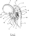
Figur 2- eine perspektivische Darstellung des Beschickungsbereichs des Wäschetrockners in explosionsartiger Darstellung mit dem Siebeinsatz und
Figur 3- eine geschnittene Seitenansicht des Teilbereichs des Wäschetrockners gemäß der
Figur 1 im Bereich der Beschickungsöffnung mit geschlossener Tür.
- Figure 1
- a sectional side view of a clothes dryer;
- Figure 2
- a perspective view of the loading area of the tumble dryer in an exploded view with the sieve insert and
- Figure 3
- a sectional side view of the portion of the clothes dryer according to FIG
Figure 1 in the area of the loading opening with the door closed.
Die
Erfindungsgemäß ist das Flusenfilter 9 aus einem Siebeinsatz 12 mit mehreren Filterebenen 13, 14 und 15 gebildet. Hierbei bildet der Siebeinsatz 12 gehäuseseitig einen Teilbereich des Einfüllringes 11 und ist darin formschlüssig eingesetzt bzw. eingebunden, wie dies in der Zusammenschau der
Gemäß der
Claims (10)
- Tumble dryer (1) comprising a drum (3) rotatably mounted in a housing (2), a loading opening (5) which can be closed by a door (4), and a fan (6) and a heating device (7) for generating a process air flow which, when the door (4) is locked, flows through the drum (3) via a corresponding opening (10) provided with a lint filter (9) in the edge (8) of the loading opening (5), which opening forms a portion of the filling ring (11), the lint filter (9) being formed from at least one screen insert (12) having a filter level (13) or a plurality of filter levels (13, 14), which screen insert is arranged below a tendon or arc (16) formed by the filling ring (11), and the region of the tendon (16) or the arc which passes over the screen insert (12) being designed as a coarse screen (17), characterised in that the screen insert (12) is formed from a crescent-shaped hollow body (18) which fills the space between the coarse screen (17) and the lower edge region (19) of the loading opening (5) in a flush manner and which forms a portion of the filling ring (11) on the front of the housing, is inserted or integrated therein in a form-fitting manner, and can be inserted/removed from the front in the horizontal direction.
- Tumble dryer according to claim 1, characterised in that the screen insert (12) is formed in several parts, a filter level (13, 14) being assigned to each part.
- Tumble dryer according to claim 2, characterised in that the parts (13, 14) each forming a filter level can be removed individually.
- Tumble dryer according to either claim 2 or claim 3, characterised in that at least one first filter level (13) is connected downstream in the screen insert (12) and at least one further filter level (14) is connected downstream as an insert in the entrance region of the air duct.
- Tumble dryer according to claim 1, characterised in that the screen insert (12) is formed in one part and comprises a plurality of filter levels (13, 14).
- Tumble dryer according to claim 1, characterised in that the screen insert (12) forms a first level (13) for a filter insert below the coarse screen (17) and a second level (14) for a further filter insert between the screen insert (12) and a depth filter 15 which is arranged in the exhaust air opening (20) and forms a third level.
- Tumble dryer according to claim 1, characterised in that the front region of the crescent-shaped screen insert (12) is sealingly covered by the lower edge of the door (4) when the door (4) is closed.
- Tumble dryer according to claim 7, characterised in that an inwardly curved inspection glass (21) is enclosed in the door (4).
- Tumble dryer according to claim 8, characterised in that the lower region of the inspection-glass edge (22) extends over the coarse screen (17) when the door (4) is closed.
- Tumble dryer according to claim 9, characterised in that when the door (4) is closed, a gap (23) which widens towards the drum (3) is formed between the lower inspection-glass edge (22) and the coarse screen (17).
Applications Claiming Priority (1)
| Application Number | Priority Date | Filing Date | Title |
|---|---|---|---|
| DE102009031097A DE102009031097B4 (en) | 2009-06-29 | 2009-06-29 | clothes dryer |
Publications (3)
| Publication Number | Publication Date |
|---|---|
| EP2273005A2 EP2273005A2 (en) | 2011-01-12 |
| EP2273005A3 EP2273005A3 (en) | 2017-11-15 |
| EP2273005B1 true EP2273005B1 (en) | 2021-02-24 |
Family
ID=42732188
Family Applications (1)
| Application Number | Title | Priority Date | Filing Date |
|---|---|---|---|
| EP10401081.4A Active EP2273005B1 (en) | 2009-06-29 | 2010-06-15 | Tumble dryer |
Country Status (3)
| Country | Link |
|---|---|
| EP (1) | EP2273005B1 (en) |
| DE (1) | DE102009031097B4 (en) |
| ES (1) | ES2854978T3 (en) |
Families Citing this family (9)
| Publication number | Priority date | Publication date | Assignee | Title |
|---|---|---|---|---|
| EP2511414B1 (en) * | 2011-04-15 | 2020-05-06 | Candy S.p.A. | Filtration system for laundry dryer |
| EP2657391B1 (en) | 2012-04-26 | 2020-02-19 | Miele & Cie. KG | Container for holding and dispensing a perfume material into the treatment area of a domestic appliance and domestic appliance with such a container |
| EP2669423B1 (en) | 2012-05-31 | 2016-03-02 | Miele & Cie. KG | Drying device for drying laundry with a container for holding and dispensing an aromatic substance |
| DE102013110938B4 (en) * | 2013-10-02 | 2016-11-17 | Miele & Cie. Kg | clothes dryer |
| DE102014105327B4 (en) * | 2014-04-15 | 2017-01-12 | Miele & Cie. Kg | clothes dryer |
| WO2016034302A1 (en) * | 2014-09-05 | 2016-03-10 | Arcelik Anonim Sirketi | A dryer comprising a fragrance source |
| EP3189184B1 (en) * | 2014-09-05 | 2020-02-12 | Arçelik Anonim Sirketi | A dryer comprising a fragrance source |
| DE102018120954A1 (en) * | 2018-08-28 | 2020-03-05 | Miele & Cie. Kg | Program controlled clothes dryer |
| CN116136046A (en) * | 2021-11-17 | 2023-05-19 | 博西华电器(江苏)有限公司 | Clothes treating apparatus |
Citations (1)
| Publication number | Priority date | Publication date | Assignee | Title |
|---|---|---|---|---|
| DE29517898U1 (en) * | 1995-11-11 | 1996-12-19 | Aeg Hausgeraete Gmbh | Lint filter device for an electric household clothes dryer |
Family Cites Families (9)
| Publication number | Priority date | Publication date | Assignee | Title |
|---|---|---|---|---|
| US3378934A (en) * | 1966-07-28 | 1968-04-23 | Gen Electric | Lint trap for clothes dryers |
| DE8437357U1 (en) * | 1984-12-20 | 1985-03-21 | Bosch-Siemens Hausgeräte GmbH, 7000 Stuttgart | HOUSEHOLD LAUNDRY DRYER WITH A FLUSH FILTER |
| GB2258720A (en) | 1991-08-15 | 1993-02-17 | Creda Ltd | Tumble dryer |
| DE9212226U1 (en) * | 1992-09-10 | 1992-11-19 | Bauknecht Hausgeraete Gmbh, 7000 Stuttgart, De | |
| DE29618169U1 (en) * | 1996-10-19 | 1998-02-19 | Aeg Hausgeraete Gmbh | Lint filter device for an electric clothes dryer |
| KR100664507B1 (en) * | 2005-10-06 | 2007-01-04 | 삼성전자주식회사 | Cloth dryer |
| DE102005056138B4 (en) * | 2005-11-23 | 2009-02-26 | Miele & Cie. Kg | clothes dryer |
| DE202007014571U1 (en) | 2007-10-16 | 2007-12-20 | Filtertek B.V., Newcastle West | Filter, in particular for tumble dryers, for catching the lint produced during the drying process |
| KR100989734B1 (en) * | 2008-06-03 | 2010-10-26 | 엘지전자 주식회사 | Clothes dryer |
-
2009
- 2009-06-29 DE DE102009031097A patent/DE102009031097B4/en not_active Expired - Fee Related
-
2010
- 2010-06-15 ES ES10401081T patent/ES2854978T3/en active Active
- 2010-06-15 EP EP10401081.4A patent/EP2273005B1/en active Active
Patent Citations (1)
| Publication number | Priority date | Publication date | Assignee | Title |
|---|---|---|---|---|
| DE29517898U1 (en) * | 1995-11-11 | 1996-12-19 | Aeg Hausgeraete Gmbh | Lint filter device for an electric household clothes dryer |
Also Published As
| Publication number | Publication date |
|---|---|
| ES2854978T3 (en) | 2021-09-23 |
| EP2273005A2 (en) | 2011-01-12 |
| DE102009031097A1 (en) | 2011-01-13 |
| DE102009031097B4 (en) | 2011-03-24 |
| EP2273005A3 (en) | 2017-11-15 |
Similar Documents
| Publication | Publication Date | Title |
|---|---|---|
| EP2273005B1 (en) | Tumble dryer | |
| EP2669423B1 (en) | Drying device for drying laundry with a container for holding and dispensing an aromatic substance | |
| EP2669422B1 (en) | Drying device for drying laundry with a container for holding and dispensing an aromatic substance | |
| DE19952751B4 (en) | Clothes dryer with a self-cleaning lint filter | |
| EP2107155A2 (en) | Laundry treatment machine, in particular laundry dryer | |
| EP2855759B1 (en) | Accommodating device for a removable filter in a domestic appliance | |
| DE102011055090B3 (en) | Laundry treatment machine such as washing machine or tumble dryer | |
| EP2923623B1 (en) | Dust filter bag for a vacuum cleaner and vacuum cleaner comprising a dust filter bag | |
| EP2559802B1 (en) | Lye pump with filter insert for a washing machine | |
| DE19745091B4 (en) | Lint filter device for an electric clothes dryer | |
| DE102008057460A1 (en) | Laundry treatment machine, particularly laundry dryer, has drum rotatably mounted in housing, feed opening locked with door, and blower, where heating device is provided for generating process air stream which flows through heat exchanger | |
| DE102014115695A1 (en) | Dryer with a container for dispensing a fragrance | |
| EP2392724A2 (en) | Household appliance, in particular laundry dryer, with a filtering device | |
| DE2406683C3 (en) | Double-walled lid for a drum-type washing machine with a jacket | |
| DE102013110933A1 (en) | Bag for filtering lint | |
| DE102014105327B4 (en) | clothes dryer | |
| WO2011054767A1 (en) | Lint filter for a domestic dryer and method for cleaning a lint filter | |
| DE2015953B2 (en) | Dishwasher with a plastic washing container and a hinged door | |
| AT376582B (en) | DRUM FILTER | |
| DE19756708A1 (en) | Laundry drier | |
| DE102013110938B4 (en) | clothes dryer | |
| DE102015110215A1 (en) | Clothes dryer with a rotatably mounted in a housing drum | |
| DE102018111775A1 (en) | Open-end spinning device and rotary valve for an open-end spinning device | |
| DE102015107112A1 (en) | Clothes dryer with a rotatably mounted in a housing drum | |
| DE3834619A1 (en) | Device for the storage of transport-protection sleeves and screws on a washing machine |
Legal Events
| Date | Code | Title | Description |
|---|---|---|---|
| PUAI | Public reference made under article 153(3) epc to a published international application that has entered the european phase |
Free format text: ORIGINAL CODE: 0009012 |
|
| AK | Designated contracting states |
Kind code of ref document: A2 Designated state(s): AL AT BE BG CH CY CZ DE DK EE ES FI FR GB GR HR HU IE IS IT LI LT LU LV MC MK MT NL NO PL PT RO SE SI SK SM TR |
|
| AX | Request for extension of the european patent |
Extension state: BA ME RS |
|
| PUAL | Search report despatched |
Free format text: ORIGINAL CODE: 0009013 |
|
| AK | Designated contracting states |
Kind code of ref document: A3 Designated state(s): AL AT BE BG CH CY CZ DE DK EE ES FI FR GB GR HR HU IE IS IT LI LT LU LV MC MK MT NL NO PL PT RO SE SI SK SM TR |
|
| AX | Request for extension of the european patent |
Extension state: BA ME RS |
|
| RIC1 | Information provided on ipc code assigned before grant |
Ipc: D06F 58/22 20060101AFI20171006BHEP |
|
| STAA | Information on the status of an ep patent application or granted ep patent |
Free format text: STATUS: REQUEST FOR EXAMINATION WAS MADE |
|
| 17P | Request for examination filed |
Effective date: 20180515 |
|
| RBV | Designated contracting states (corrected) |
Designated state(s): AL AT BE BG CH CY CZ DE DK EE ES FI FR GB GR HR HU IE IS IT LI LT LU LV MC MK MT NL NO PL PT RO SE SI SK SM TR |
|
| STAA | Information on the status of an ep patent application or granted ep patent |
Free format text: STATUS: EXAMINATION IS IN PROGRESS |
|
| 17Q | First examination report despatched |
Effective date: 20200414 |
|
| GRAP | Despatch of communication of intention to grant a patent |
Free format text: ORIGINAL CODE: EPIDOSNIGR1 |
|
| STAA | Information on the status of an ep patent application or granted ep patent |
Free format text: STATUS: GRANT OF PATENT IS INTENDED |
|
| INTG | Intention to grant announced |
Effective date: 20201109 |
|
| GRAS | Grant fee paid |
Free format text: ORIGINAL CODE: EPIDOSNIGR3 |
|
| GRAA | (expected) grant |
Free format text: ORIGINAL CODE: 0009210 |
|
| STAA | Information on the status of an ep patent application or granted ep patent |
Free format text: STATUS: THE PATENT HAS BEEN GRANTED |
|
| AK | Designated contracting states |
Kind code of ref document: B1 Designated state(s): AL AT BE BG CH CY CZ DE DK EE ES FI FR GB GR HR HU IE IS IT LI LT LU LV MC MK MT NL NO PL PT RO SE SI SK SM TR |
|
| REG | Reference to a national code |
Ref country code: GB Ref legal event code: FG4D Free format text: NOT ENGLISH |
|
| REG | Reference to a national code |
Ref country code: CH Ref legal event code: EP |
|
| REG | Reference to a national code |
Ref country code: DE Ref legal event code: R096 Ref document number: 502010016855 Country of ref document: DE |
|
| REG | Reference to a national code |
Ref country code: AT Ref legal event code: REF Ref document number: 1364572 Country of ref document: AT Kind code of ref document: T Effective date: 20210315 |
|
| REG | Reference to a national code |
Ref country code: IE Ref legal event code: FG4D Free format text: LANGUAGE OF EP DOCUMENT: GERMAN |
|
| REG | Reference to a national code |
Ref country code: SE Ref legal event code: TRGR |
|
| REG | Reference to a national code |
Ref country code: NL Ref legal event code: FP |
|
| REG | Reference to a national code |
Ref country code: LT Ref legal event code: MG9D |
|
| PG25 | Lapsed in a contracting state [announced via postgrant information from national office to epo] |
Ref country code: BG Free format text: LAPSE BECAUSE OF FAILURE TO SUBMIT A TRANSLATION OF THE DESCRIPTION OR TO PAY THE FEE WITHIN THE PRESCRIBED TIME-LIMIT Effective date: 20210524 Ref country code: NO Free format text: LAPSE BECAUSE OF FAILURE TO SUBMIT A TRANSLATION OF THE DESCRIPTION OR TO PAY THE FEE WITHIN THE PRESCRIBED TIME-LIMIT Effective date: 20210524 Ref country code: PT Free format text: LAPSE BECAUSE OF FAILURE TO SUBMIT A TRANSLATION OF THE DESCRIPTION OR TO PAY THE FEE WITHIN THE PRESCRIBED TIME-LIMIT Effective date: 20210624 Ref country code: HR Free format text: LAPSE BECAUSE OF FAILURE TO SUBMIT A TRANSLATION OF THE DESCRIPTION OR TO PAY THE FEE WITHIN THE PRESCRIBED TIME-LIMIT Effective date: 20210224 Ref country code: FI Free format text: LAPSE BECAUSE OF FAILURE TO SUBMIT A TRANSLATION OF THE DESCRIPTION OR TO PAY THE FEE WITHIN THE PRESCRIBED TIME-LIMIT Effective date: 20210224 Ref country code: GR Free format text: LAPSE BECAUSE OF FAILURE TO SUBMIT A TRANSLATION OF THE DESCRIPTION OR TO PAY THE FEE WITHIN THE PRESCRIBED TIME-LIMIT Effective date: 20210525 Ref country code: LT Free format text: LAPSE BECAUSE OF FAILURE TO SUBMIT A TRANSLATION OF THE DESCRIPTION OR TO PAY THE FEE WITHIN THE PRESCRIBED TIME-LIMIT Effective date: 20210224 |
|
| PG25 | Lapsed in a contracting state [announced via postgrant information from national office to epo] |
Ref country code: PL Free format text: LAPSE BECAUSE OF FAILURE TO SUBMIT A TRANSLATION OF THE DESCRIPTION OR TO PAY THE FEE WITHIN THE PRESCRIBED TIME-LIMIT Effective date: 20210224 Ref country code: LV Free format text: LAPSE BECAUSE OF FAILURE TO SUBMIT A TRANSLATION OF THE DESCRIPTION OR TO PAY THE FEE WITHIN THE PRESCRIBED TIME-LIMIT Effective date: 20210224 |
|
| REG | Reference to a national code |
Ref country code: ES Ref legal event code: FG2A Ref document number: 2854978 Country of ref document: ES Kind code of ref document: T3 Effective date: 20210923 |
|
| PG25 | Lapsed in a contracting state [announced via postgrant information from national office to epo] |
Ref country code: IS Free format text: LAPSE BECAUSE OF FAILURE TO SUBMIT A TRANSLATION OF THE DESCRIPTION OR TO PAY THE FEE WITHIN THE PRESCRIBED TIME-LIMIT Effective date: 20210624 |
|
| PG25 | Lapsed in a contracting state [announced via postgrant information from national office to epo] |
Ref country code: CZ Free format text: LAPSE BECAUSE OF FAILURE TO SUBMIT A TRANSLATION OF THE DESCRIPTION OR TO PAY THE FEE WITHIN THE PRESCRIBED TIME-LIMIT Effective date: 20210224 Ref country code: EE Free format text: LAPSE BECAUSE OF FAILURE TO SUBMIT A TRANSLATION OF THE DESCRIPTION OR TO PAY THE FEE WITHIN THE PRESCRIBED TIME-LIMIT Effective date: 20210224 Ref country code: SM Free format text: LAPSE BECAUSE OF FAILURE TO SUBMIT A TRANSLATION OF THE DESCRIPTION OR TO PAY THE FEE WITHIN THE PRESCRIBED TIME-LIMIT Effective date: 20210224 |
|
| REG | Reference to a national code |
Ref country code: DE Ref legal event code: R097 Ref document number: 502010016855 Country of ref document: DE |
|
| PG25 | Lapsed in a contracting state [announced via postgrant information from national office to epo] |
Ref country code: SK Free format text: LAPSE BECAUSE OF FAILURE TO SUBMIT A TRANSLATION OF THE DESCRIPTION OR TO PAY THE FEE WITHIN THE PRESCRIBED TIME-LIMIT Effective date: 20210224 Ref country code: DK Free format text: LAPSE BECAUSE OF FAILURE TO SUBMIT A TRANSLATION OF THE DESCRIPTION OR TO PAY THE FEE WITHIN THE PRESCRIBED TIME-LIMIT Effective date: 20210224 Ref country code: RO Free format text: LAPSE BECAUSE OF FAILURE TO SUBMIT A TRANSLATION OF THE DESCRIPTION OR TO PAY THE FEE WITHIN THE PRESCRIBED TIME-LIMIT Effective date: 20210224 |
|
| PLBE | No opposition filed within time limit |
Free format text: ORIGINAL CODE: 0009261 |
|
| STAA | Information on the status of an ep patent application or granted ep patent |
Free format text: STATUS: NO OPPOSITION FILED WITHIN TIME LIMIT |
|
| PG25 | Lapsed in a contracting state [announced via postgrant information from national office to epo] |
Ref country code: AL Free format text: LAPSE BECAUSE OF FAILURE TO SUBMIT A TRANSLATION OF THE DESCRIPTION OR TO PAY THE FEE WITHIN THE PRESCRIBED TIME-LIMIT Effective date: 20210224 Ref country code: MC Free format text: LAPSE BECAUSE OF FAILURE TO SUBMIT A TRANSLATION OF THE DESCRIPTION OR TO PAY THE FEE WITHIN THE PRESCRIBED TIME-LIMIT Effective date: 20210224 |
|
| REG | Reference to a national code |
Ref country code: CH Ref legal event code: PL |
|
| 26N | No opposition filed |
Effective date: 20211125 |
|
| PG25 | Lapsed in a contracting state [announced via postgrant information from national office to epo] |
Ref country code: SI Free format text: LAPSE BECAUSE OF FAILURE TO SUBMIT A TRANSLATION OF THE DESCRIPTION OR TO PAY THE FEE WITHIN THE PRESCRIBED TIME-LIMIT Effective date: 20210224 |
|
| PG25 | Lapsed in a contracting state [announced via postgrant information from national office to epo] |
Ref country code: LU Free format text: LAPSE BECAUSE OF NON-PAYMENT OF DUE FEES Effective date: 20210615 |
|
| PG25 | Lapsed in a contracting state [announced via postgrant information from national office to epo] |
Ref country code: LI Free format text: LAPSE BECAUSE OF NON-PAYMENT OF DUE FEES Effective date: 20210630 Ref country code: IE Free format text: LAPSE BECAUSE OF NON-PAYMENT OF DUE FEES Effective date: 20210615 Ref country code: CH Free format text: LAPSE BECAUSE OF NON-PAYMENT OF DUE FEES Effective date: 20210630 |
|
| PG25 | Lapsed in a contracting state [announced via postgrant information from national office to epo] |
Ref country code: IS Free format text: LAPSE BECAUSE OF FAILURE TO SUBMIT A TRANSLATION OF THE DESCRIPTION OR TO PAY THE FEE WITHIN THE PRESCRIBED TIME-LIMIT Effective date: 20210624 |
|
| PGFP | Annual fee paid to national office [announced via postgrant information from national office to epo] |
Ref country code: SE Payment date: 20220622 Year of fee payment: 13 Ref country code: NL Payment date: 20220627 Year of fee payment: 13 |
|
| REG | Reference to a national code |
Ref country code: AT Ref legal event code: MM01 Ref document number: 1364572 Country of ref document: AT Kind code of ref document: T Effective date: 20210615 |
|
| PGFP | Annual fee paid to national office [announced via postgrant information from national office to epo] |
Ref country code: BE Payment date: 20220627 Year of fee payment: 13 |
|
| PG25 | Lapsed in a contracting state [announced via postgrant information from national office to epo] |
Ref country code: AT Free format text: LAPSE BECAUSE OF NON-PAYMENT OF DUE FEES Effective date: 20210615 |
|
| PGFP | Annual fee paid to national office [announced via postgrant information from national office to epo] |
Ref country code: ES Payment date: 20220714 Year of fee payment: 13 |
|
| PG25 | Lapsed in a contracting state [announced via postgrant information from national office to epo] |
Ref country code: HU Free format text: LAPSE BECAUSE OF FAILURE TO SUBMIT A TRANSLATION OF THE DESCRIPTION OR TO PAY THE FEE WITHIN THE PRESCRIBED TIME-LIMIT; INVALID AB INITIO Effective date: 20100615 Ref country code: CY Free format text: LAPSE BECAUSE OF FAILURE TO SUBMIT A TRANSLATION OF THE DESCRIPTION OR TO PAY THE FEE WITHIN THE PRESCRIBED TIME-LIMIT Effective date: 20210224 |
|
| P01 | Opt-out of the competence of the unified patent court (upc) registered |
Effective date: 20230529 |
|
| PGFP | Annual fee paid to national office [announced via postgrant information from national office to epo] |
Ref country code: FR Payment date: 20230622 Year of fee payment: 14 Ref country code: DE Payment date: 20230630 Year of fee payment: 14 |
|
| PGFP | Annual fee paid to national office [announced via postgrant information from national office to epo] |
Ref country code: IT Payment date: 20230620 Year of fee payment: 14 Ref country code: GB Payment date: 20230620 Year of fee payment: 14 |
|
| REG | Reference to a national code |
Ref country code: SE Ref legal event code: EUG |
|
| REG | Reference to a national code |
Ref country code: NL Ref legal event code: MM Effective date: 20230701 |
|
| REG | Reference to a national code |
Ref country code: BE Ref legal event code: MM Effective date: 20230630 |
|
| PG25 | Lapsed in a contracting state [announced via postgrant information from national office to epo] |
Ref country code: NL Free format text: LAPSE BECAUSE OF NON-PAYMENT OF DUE FEES Effective date: 20230701 |
|
| REG | Reference to a national code |
Ref country code: DE Ref legal event code: R084 Ref document number: 502010016855 Country of ref document: DE |
|
| PG25 | Lapsed in a contracting state [announced via postgrant information from national office to epo] |
Ref country code: MK Free format text: LAPSE BECAUSE OF FAILURE TO SUBMIT A TRANSLATION OF THE DESCRIPTION OR TO PAY THE FEE WITHIN THE PRESCRIBED TIME-LIMIT Effective date: 20210224 |