EP2272425A2 - Génération d'une image présentant des annotations dans une zone de travail stérile - Google Patents
Génération d'une image présentant des annotations dans une zone de travail stérile Download PDFInfo
- Publication number
- EP2272425A2 EP2272425A2 EP10185806A EP10185806A EP2272425A2 EP 2272425 A2 EP2272425 A2 EP 2272425A2 EP 10185806 A EP10185806 A EP 10185806A EP 10185806 A EP10185806 A EP 10185806A EP 2272425 A2 EP2272425 A2 EP 2272425A2
- Authority
- EP
- European Patent Office
- Prior art keywords
- sterile
- image
- area
- processing unit
- image processing
- Prior art date
- Legal status (The legal status is an assumption and is not a legal conclusion. Google has not performed a legal analysis and makes no representation as to the accuracy of the status listed.)
- Ceased
Links
- 238000012545 processing Methods 0.000 claims abstract description 68
- 238000000926 separation method Methods 0.000 claims description 8
- 238000002955 isolation Methods 0.000 claims description 7
- 230000005540 biological transmission Effects 0.000 claims description 6
- 238000006243 chemical reaction Methods 0.000 claims description 4
- 239000011159 matrix material Substances 0.000 claims 1
- 238000000034 method Methods 0.000 description 6
- 238000012549 training Methods 0.000 description 5
- 238000011282 treatment Methods 0.000 description 3
- 238000013459 approach Methods 0.000 description 2
- 238000004891 communication Methods 0.000 description 2
- 238000010586 diagram Methods 0.000 description 2
- 238000003384 imaging method Methods 0.000 description 2
- 210000000056 organ Anatomy 0.000 description 2
- 238000001356 surgical procedure Methods 0.000 description 2
- 210000001835 viscera Anatomy 0.000 description 2
- 239000003814 drug Substances 0.000 description 1
- 238000005516 engineering process Methods 0.000 description 1
- 239000000463 material Substances 0.000 description 1
- 230000006855 networking Effects 0.000 description 1
- 238000012946 outsourcing Methods 0.000 description 1
- 238000002360 preparation method Methods 0.000 description 1
- 238000011477 surgical intervention Methods 0.000 description 1
- 238000013519 translation Methods 0.000 description 1
Images
Classifications
-
- A—HUMAN NECESSITIES
- A61—MEDICAL OR VETERINARY SCIENCE; HYGIENE
- A61B—DIAGNOSIS; SURGERY; IDENTIFICATION
- A61B90/00—Instruments, implements or accessories specially adapted for surgery or diagnosis and not covered by any of the groups A61B1/00 - A61B50/00, e.g. for luxation treatment or for protecting wound edges
- A61B90/36—Image-producing devices or illumination devices not otherwise provided for
-
- A—HUMAN NECESSITIES
- A61—MEDICAL OR VETERINARY SCIENCE; HYGIENE
- A61B—DIAGNOSIS; SURGERY; IDENTIFICATION
- A61B5/00—Measuring for diagnostic purposes; Identification of persons
- A61B5/0002—Remote monitoring of patients using telemetry, e.g. transmission of vital signals via a communication network
- A61B5/0004—Remote monitoring of patients using telemetry, e.g. transmission of vital signals via a communication network characterised by the type of physiological signal transmitted
- A61B5/0013—Medical image data
-
- A—HUMAN NECESSITIES
- A61—MEDICAL OR VETERINARY SCIENCE; HYGIENE
- A61B—DIAGNOSIS; SURGERY; IDENTIFICATION
- A61B90/00—Instruments, implements or accessories specially adapted for surgery or diagnosis and not covered by any of the groups A61B1/00 - A61B50/00, e.g. for luxation treatment or for protecting wound edges
- A61B90/36—Image-producing devices or illumination devices not otherwise provided for
- A61B90/37—Surgical systems with images on a monitor during operation
- A61B2090/371—Surgical systems with images on a monitor during operation with simultaneous use of two cameras
-
- A—HUMAN NECESSITIES
- A61—MEDICAL OR VETERINARY SCIENCE; HYGIENE
- A61B—DIAGNOSIS; SURGERY; IDENTIFICATION
- A61B90/00—Instruments, implements or accessories specially adapted for surgery or diagnosis and not covered by any of the groups A61B1/00 - A61B50/00, e.g. for luxation treatment or for protecting wound edges
- A61B90/36—Image-producing devices or illumination devices not otherwise provided for
- A61B90/37—Surgical systems with images on a monitor during operation
-
- A—HUMAN NECESSITIES
- A61—MEDICAL OR VETERINARY SCIENCE; HYGIENE
- A61B—DIAGNOSIS; SURGERY; IDENTIFICATION
- A61B90/00—Instruments, implements or accessories specially adapted for surgery or diagnosis and not covered by any of the groups A61B1/00 - A61B50/00, e.g. for luxation treatment or for protecting wound edges
- A61B90/40—Apparatus fixed or close to patients specially adapted for providing an aseptic surgical environment
Definitions
- the present invention relates to an apparatus for generating an annotated image in a sterile work area of a medical facility.
- miniaturized cameras are introduced into the body of a patient, and the image taken with the camera is displayed to the attending physician on a monitor installed in his workspace.
- the attending physician can on this For example, examine an internal organ or a joint for diagnostic purposes and perform surgery minimally invasive.
- the monitor is arranged in the working area of the doctor, ie in the sterile area. The doctor has the opportunity to follow all interventions that he makes on the patient "live" on the monitor, the corresponding monitor image is recorded, for example, with an endoscopic camera.
- the invention is not limited to applications in which images are generated by means of endoscopic cameras. Although this is a preferred application, the origin of the images plays a minor role in the present invention.
- the images can also be X-ray images or recordings from an archive, which are recorded for example for comparison purposes on the monitor in the workspace of the doctor.
- One way to meet the need described above would be to use the commercially available equipment outside of the sterile work area, where the relevant image from the sterile work area would have to be additionally transferred to a second monitor located outside the sterile area.
- the disadvantage here is that the attending physician must leave the sterile work area to insert processing notes in the displayed image.
- Another option would be to retrofit commercially available equipment to meet the requirements for use in the sterile operating room of an operating room.
- the proposed method and apparatus are thus based on the idea that both the primary image to be annotated and the input data representing the processing indicia are "out of the box", i.e., out of the sterile area. into a non-sterile area.
- the primary image and the input data can then be combined in a relatively simple and cost-effective manner, advantageously for this sub-step a commercially available and thus not approved for medical applications per se image processing unit is used.
- the processing of the image provided with processing comments is therefore outsourced in a non-critical area.
- the "outsourcing" is done so that a treating physician can still generate the input data from his sterile work area.
- the proposed path thus combines the advantages of the alternative solutions mentioned above.
- the new method and apparatus have the advantage that the secondary image provided with the processing marks is immediately available for further processing outside of the sterile area.
- This further processing can be, for example, the display on a remote training monitor and / or the archiving in an electronic patient file.
- the new system therefore offers a wider range of applications.
- the primary image is a medical image of a patient, in particular a recording produced endoscopically in the sterile work area.
- the advantages of the invention are particularly clear advantage.
- the analysis of a medical admission of a patient and in particular the analysis of a current admission of the patient during a treatment is an application which becomes simpler and clearer by the provision of processing comments. For example, misunderstandings in a difficult operation in which several treating physicians are involved can be more easily avoided in this preferred embodiment.
- the input device is a touch-sensitive screen, which preferably also forms the display unit.
- Touch screens are known per se and are already used as display and control units in medical facilities.
- a touch-sensitive screen has the particular advantage that the attending physician can very easily and quickly generate processing marks with the help of his hands.
- a touch screen is well suited as an input device for the sterile work area, and it requires no extra space, especially in the preferred embodiment.
- the input data in the preferred embodiment is in particular the coordinates on the touch-sensitive Screen on which contact by the attending physician is detected.
- the input data is transmitted to the image processing unit via a galvanic separation point.
- This embodiment has the advantage that the sterile work area and the devices used therein are very reliably sealed off from the non-sterile exterior area. The functional reliability and functional reliability of the overall device is thereby increased.
- the input data is subjected to protocol conversion during transmission to the image processing unit.
- a protocol converter is provided, which is further preferably designed in the form of an interface module, in particular an interface card.
- This embodiment has the advantage that any and possibly interchangeable image processing unit can be used solely by adapting the protocol converter. In particular, this facilitates the use of commercially available image processing units, which enables a particularly cost-effective implementation.
- the input data is transmitted in a digital format to the image processing unit. Furthermore, it is preferred if the primary image is transmitted as an analog image signal to the image processing unit.
- the input data could also be transmitted in analog form or the primary image in digital form to the image processing unit.
- the preferred embodiments however, on the other hand facilitate the practical realization.
- a protocol conversion for digital input data relatively easy and inexpensive to be realized by software.
- the transmission of the primary image as an analog image signal is simpler and faster to realize with current means than in digital form.
- cost-effective and proven components can be used in this case.
- the secondary image is displayed on a second display unit, which is arranged outside the sterile working area.
- This embodiment takes advantage of the possibilities of the new method in a particularly advantageous manner, as this, for example, training and training, data archiving and video conferencing, in which far-seated professionals are involved, are significantly simplified.
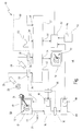
- a medical device in its entirety is designated by the reference numeral 10.
- the device 10 includes a display unit 12, which in the preferred embodiment is a touch screen.
- the display unit 12 could also be an analog CRT monitor, a simple LCD monitor, a beamer, or any other display unit.
- the touch screen 12 also simultaneously forms an input device, here represented by the hand 14 of an operator.
- the reference numeral 16 designates a medical computer PC (personal computer) equipped with a so-called frame grabber card 18.
- the task of the frame grabber card 18 is to record an analog video signal, in particular a so-called S-VHS signal, to digitize it and then to make it available to the internal processing unit (not shown here) of the PC.
- the PC 16 is connected to the touch-sensitive screen 12 via two connections 20, 22.
- the connection 20 is a conventional video signal connection, for example a VGA connection or a DVI connection, via which the display unit is connected to a PC.
- the PC 16 thus controls the display unit 12 via the connection 20.
- connection 22 in the preferred embodiment is a digital data connection through which input data 24 is transmitted from the touch screen 12 to the PC 16.
- the connection 22 is here in particular a serial RS-232 connection. However, it could also be, for example, a PS2 connection, a USB connection or a parallel data connection.
- the PC 16 evaluates the input data 24 as if it were input data from a mouse.
- the reference numeral 26 denotes a camera unit, which in particular includes an endoscopic camera and a corresponding control device (not shown separately). With the camera unit 26, for example, an internal organ 28 of a patient not otherwise shown here is recorded.
- the camera unit 26 is connected via a buffer amplifier 30 or a separating transformer with a so-called video crossbar. Deviating from the block diagram representation shown here, the isolating amplifier 30 can also be integrated, for example, in the camera unit 26 or the mentioned control unit.
- the video router 32 has a plurality of inputs 34, 36, 38, 40, to each of which a video signal source can be connected. Furthermore, has the Video crossbar 32 a series of outputs 42, 44, 46, at which video signals are output. In the embodiment shown, both the signals at the video inputs 34-40 and the video signals at the outputs 42-46 are S-VHS signals. However, other types of video signals can be used here as well.
- the camera unit 26 is connected via the isolating amplifier 30 to the input 34 of the video crossbar 32.
- a further camera unit 48 is connected via a further isolation amplifier.
- the camera unit 48 here is, for example, a 3D camera with a corresponding control unit, which makes it possible to record three-dimensional images.
- other types of video signal sources can also be connected here.
- the reference numeral 50 designates here by way of example for another video source a CD or DVD player which is connected to the input 38 of the video crossbar 32.
- the CD or DVD player 50 serves, for example, to provide archived image material for output on the display unit 12.
- An image processing unit 52 is connected to the input 40 of the video crossbar 32.
- the image processing unit 52 is preferably a commercially available image processing unit for superimposing handwritten processing marks on a video image. Preferably, this is a unit sold by Boeckeler Instruments Inc., 4650 South Butterfield Drive, Arlington, Ariz., USA under the name "Pointmaker®” PVI-44.
- the image processing unit 52 is also connected to the output 46 of the video crossbar 32 so that a loop is formed.
- a second display unit 54 is connected here.
- the output 42 is connected to the frame grabber card 18 via a further isolation amplifier 30.
- the configuration shown is exemplary and, in particular, the second camera unit 48, the CD / DVD player 50 and the second Display unit 54 are not required for the realization of the invention.
- the use of the video router 32 is here only a preferred embodiment.
- the task of the video router 32 is to selectively switch on the video signals applied to the various inputs 34-40 to one or more of the outputs 42-46.
- the isolation amplifiers 30 are preferably used in order to ensure electrical isolation between the sterile working area (designated here by reference numeral 56) and the non-sterile area 58.
- the separation between the sterile area 56 and the non-sterile area 58 is symbolically indicated here by a line 60.
- the reference numeral 62 here also denotes a digitizer tray on which one can make manual inputs with the aid of a pen 64, which are read in and processed by the image processing unit 52. Accordingly, the digitizer tray 62 is connected to the image processing unit 52 via a corresponding port. Also, the Digitizertablett 62 is not mandatory for the practical realization of the invention and therefore optional.
- the reference numeral 66 further denotes an interface unit, which is equipped in the present embodiment with an interface module 68 in the form of a plug-in card (board).
- the interface unit 66 is connected via the interface module 68 to a further input of the image processing unit 52.
- the interface unit 66 is connected to the PC 16 via a further isolation amplifier 30 (which may also be integrated in the interface unit 66).
- the connection between the PC 16 and the interface unit 66 is a digital bus connection, in particular a CAN-based bus connection as described by the assignee of the present invention under the designation SCB for the Networking of medical devices is offered.
- the connection between the interface module 68 and the image processing unit 52 is an RS-232 connection in the preferred embodiment. Alternatively, however, it could also be a USB connection, a parallel data connection or another, preferably standardized data connection.
- the interface module 68 performs protocol translation by translating input data 24 (in the preferred embodiment in SCB connection data format) received from the PC 16 into the digital data format of the RS-232 link to the image processing unit 52.
- the attending physician now has the option to mark 14 areas on the touch screen with his or her hand.
- the corresponding coordinates are transmitted as input data 24 to the PC 16 and detected there as mouse movements.
- the attending physician can, among other things, control medical devices (not shown here) connected to the PC 16, such as, for example, insufflators, an operating table or also the surgical lighting.
- control medical devices not shown here
- the PC 16 can set the PC 16 by a corresponding input command in a "marking or drawing mode" in which subsequent inputs on the touch-sensitive screen 12 are interpreted as processing notes.
- the PC 16 converts the then detected mouse movements into graphical symbols.
- a graphic symbol in the form of a hand-drawn marking arrow is designated by the reference numeral 70 in the figure.
- the icon 70 is not displayed directly on the display unit 12. Rather, the PC 16 sends the mouse coordinates detected by it to the interface unit 66, where they are converted by means of the interface module 68 in the data format of the image processing unit 52.
- the image processing unit 52 also receives, via the output 46 of the video router 32, the primary image and overlays the icon 70.
- the combined image then transmits the image processing unit 52 as a secondary image to the video router 32 (input 40). From there it passes via the frame grabber card 18 again to the display unit 12, on which now the secondary image 72 provided with the symbol 70 is displayed.
- the attending physician may then insert further tags or comments which are displayed again on the display unit 12 in the same manner, with the image initially displayed on the display unit 12 being the primary picture in the sense of the present invention.
- the secondary image 72 is also displayed on the remote display unit 54, which is available for example for training purposes or for data archiving.
- an interface module for use in a device according to claim 9 adapted to input data (24) from an input device (12) located in the sterile workspace (56) into a data format for an image processing unit located outside of the sterile workspace (56) (52) implement.
- the primary image is a medical image of a patient (28), in particular a photograph produced endoscopically in the sterile work area (56).
- a touch-sensitive screen (12) is provided as the input device, which preferably also forms the display unit.
- the input data (24) are transmitted to the image processing unit (52) via a galvanic separation point (30).
- the input data (24) are subjected to protocol conversion during transmission to the image processing unit (52).
- the input data (24) are transmitted in a digital format to the image processing unit (52).
- the primary image is transmitted as an analog image signal to the image processing unit (52).
- the secondary image (72) is displayed on a second display unit (54) which is arranged outside the sterile working area (56).
Landscapes
- Health & Medical Sciences (AREA)
- Life Sciences & Earth Sciences (AREA)
- Engineering & Computer Science (AREA)
- Surgery (AREA)
- General Health & Medical Sciences (AREA)
- Veterinary Medicine (AREA)
- Pathology (AREA)
- Biomedical Technology (AREA)
- Heart & Thoracic Surgery (AREA)
- Medical Informatics (AREA)
- Molecular Biology (AREA)
- Animal Behavior & Ethology (AREA)
- Nuclear Medicine, Radiotherapy & Molecular Imaging (AREA)
- Public Health (AREA)
- Radiology & Medical Imaging (AREA)
- Physiology (AREA)
- Computer Networks & Wireless Communication (AREA)
- Physics & Mathematics (AREA)
- Biophysics (AREA)
- Oral & Maxillofacial Surgery (AREA)
- Closed-Circuit Television Systems (AREA)
- Measuring And Recording Apparatus For Diagnosis (AREA)
- Magnetic Resonance Imaging Apparatus (AREA)
- Endoscopes (AREA)
- Processing Or Creating Images (AREA)
Applications Claiming Priority (2)
| Application Number | Priority Date | Filing Date | Title |
|---|---|---|---|
| DE10349649A DE10349649B3 (de) | 2003-10-17 | 2003-10-17 | Verfahren und Vorrichtung zum Erzeugen eines mit Bearbeitungsvermerken versehenen Bildes in einem sterilen Arbeitsbereich einer medizinischen Einrichtung |
| EP04790168A EP1675504B1 (fr) | 2003-10-17 | 2004-10-07 | Generation d'une image presentant des annotations de traitement dans une zone de travail sterile |
Related Parent Applications (1)
| Application Number | Title | Priority Date | Filing Date |
|---|---|---|---|
| EP04790168.1 Division | 2004-10-07 |
Publications (3)
| Publication Number | Publication Date |
|---|---|
| EP2272425A2 true EP2272425A2 (fr) | 2011-01-12 |
| EP2272425A8 EP2272425A8 (fr) | 2011-02-23 |
| EP2272425A3 EP2272425A3 (fr) | 2012-05-02 |
Family
ID=34442235
Family Applications (2)
| Application Number | Title | Priority Date | Filing Date |
|---|---|---|---|
| EP04790168A Expired - Lifetime EP1675504B1 (fr) | 2003-10-17 | 2004-10-07 | Generation d'une image presentant des annotations de traitement dans une zone de travail sterile |
| EP10185806A Ceased EP2272425A3 (fr) | 2003-10-17 | 2004-10-07 | Génération d'une image présentant des annotations dans une zone de travail stérile |
Family Applications Before (1)
| Application Number | Title | Priority Date | Filing Date |
|---|---|---|---|
| EP04790168A Expired - Lifetime EP1675504B1 (fr) | 2003-10-17 | 2004-10-07 | Generation d'une image presentant des annotations de traitement dans une zone de travail sterile |
Country Status (4)
| Country | Link |
|---|---|
| US (1) | US8848987B2 (fr) |
| EP (2) | EP1675504B1 (fr) |
| DE (1) | DE10349649B3 (fr) |
| WO (1) | WO2005037093A1 (fr) |
Families Citing this family (19)
| Publication number | Priority date | Publication date | Assignee | Title |
|---|---|---|---|---|
| US7361170B2 (en) | 2001-11-21 | 2008-04-22 | E-Z-Em, Inc. | Device, system, kit or method for collecting effluent from an individual |
| US9492240B2 (en) | 2009-06-16 | 2016-11-15 | Intuitive Surgical Operations, Inc. | Virtual measurement tool for minimally invasive surgery |
| US8971597B2 (en) | 2005-05-16 | 2015-03-03 | Intuitive Surgical Operations, Inc. | Efficient vision and kinematic data fusion for robotic surgical instruments and other applications |
| US7697827B2 (en) | 2005-10-17 | 2010-04-13 | Konicek Jeffrey C | User-friendlier interfaces for a camera |
| US7806850B2 (en) | 2005-10-24 | 2010-10-05 | Bracco Diagnostics Inc. | Insufflating system, method, and computer program product for controlling the supply of a distending media to an endoscopic device |
| US7907166B2 (en) | 2005-12-30 | 2011-03-15 | Intuitive Surgical Operations, Inc. | Stereo telestration for robotic surgery |
| WO2008084696A1 (fr) * | 2006-12-27 | 2008-07-17 | Kyocera Corporation | Récepteur de diffusion |
| AU2008261534B2 (en) | 2007-06-15 | 2014-01-09 | Orthosoft Ulc | Computer-assisted surgery system and method |
| PL2848192T3 (pl) | 2007-10-15 | 2022-05-02 | University Of Maryland, Baltimore | Urządzenie do zastosowania w badaniu okrężnicy pacjenta |
| US8830224B2 (en) | 2008-12-31 | 2014-09-09 | Intuitive Surgical Operations, Inc. | Efficient 3-D telestration for local robotic proctoring |
| US9155592B2 (en) | 2009-06-16 | 2015-10-13 | Intuitive Surgical Operations, Inc. | Virtual measurement tool for minimally invasive surgery |
| EP2643037B1 (fr) | 2010-11-24 | 2017-04-26 | Bracco Diagnostics Inc. | Système pour fournir et régler l'apport d'un milieu de distension en vue d'une colonographie ct |
| US11412998B2 (en) | 2011-02-10 | 2022-08-16 | Karl Storz Imaging, Inc. | Multi-source medical display |
| US10674968B2 (en) | 2011-02-10 | 2020-06-09 | Karl Storz Imaging, Inc. | Adjustable overlay patterns for medical display |
| US10631712B2 (en) | 2011-02-10 | 2020-04-28 | Karl Storz Imaging, Inc. | Surgeon's aid for medical display |
| US20140138270A1 (en) | 2012-11-16 | 2014-05-22 | Krishnan K. Ghosh | Surgical system |
| US10868950B2 (en) * | 2018-12-12 | 2020-12-15 | Karl Storz Imaging, Inc. | Systems and methods for operating video medical scopes using a virtual camera control unit |
| US11625825B2 (en) | 2019-01-30 | 2023-04-11 | Covidien Lp | Method for displaying tumor location within endoscopic images |
| DE102024103538B3 (de) * | 2024-02-08 | 2025-05-22 | Schölly Fiberoptic GmbH | Medizinisches Visualisierungssystem, medizinisches Operationssystem sowie Verfahren zum Visualisieren eines Videobilddatenstroms |
Citations (1)
| Publication number | Priority date | Publication date | Assignee | Title |
|---|---|---|---|---|
| US5788688A (en) | 1992-11-05 | 1998-08-04 | Bauer Laboratories, Inc. | Surgeon's command and control |
Family Cites Families (20)
| Publication number | Priority date | Publication date | Assignee | Title |
|---|---|---|---|---|
| US3772514A (en) * | 1971-11-08 | 1973-11-13 | Capintec Inc | Isolation amplifier |
| US4989253A (en) * | 1988-04-15 | 1991-01-29 | The Montefiore Hospital Association Of Western Pennsylvania | Voice activated microscope |
| US4877016A (en) | 1988-07-29 | 1989-10-31 | Kantor Edward A | Video endoscopic microscope |
| US5257998A (en) * | 1989-09-20 | 1993-11-02 | Mitaka Kohki Co., Ltd. | Medical three-dimensional locating apparatus |
| US5699798A (en) * | 1990-08-10 | 1997-12-23 | University Of Washington | Method for optically imaging solid tumor tissue |
| DE19534312A1 (de) * | 1995-09-15 | 1997-03-20 | Norbert Schmidt | Verfahren und Anordnung zur Ausgabe von Bildinformationen aus chirurgischen OP-Sälen |
| US6078681A (en) * | 1996-03-18 | 2000-06-20 | Marine Biological Laboratory | Analytical imaging system and process |
| US5970980A (en) * | 1996-07-12 | 1999-10-26 | Adair; Edwin L. | Sterile encapsulated operating room video monitor and video monitor support device |
| DE19648935B4 (de) * | 1996-11-26 | 2008-05-15 | IMEDOS Intelligente Optische Systeme der Medizin- und Messtechnik GmbH | Vorrichtung und Verfahren zur Untersuchung von Gefäßen |
| DE19858421A1 (de) * | 1998-12-17 | 2000-06-29 | Siemens Ag | Zur Anbindung an ein Netzwerk vorgesehenes medizinisches Bildsystem |
| CA2272040A1 (fr) * | 1999-05-13 | 2000-11-13 | Ecole Polytechnique | Systeme de camera d'observation robotisee pour utilisation en salle d'operation |
| US6791601B1 (en) * | 1999-11-11 | 2004-09-14 | Stryker Corporation | Multi-function image and video capture device for use in an endoscopic camera system |
| US6591239B1 (en) * | 1999-12-09 | 2003-07-08 | Steris Inc. | Voice controlled surgical suite |
| US6639789B2 (en) * | 2000-07-12 | 2003-10-28 | Karl Storz Gmbh & Co. Kg | Instrument and service unit for a surgical operating area |
| JP2002263063A (ja) * | 2001-03-12 | 2002-09-17 | Asahi Optical Co Ltd | 内視鏡システム |
| US20050272971A1 (en) * | 2002-08-30 | 2005-12-08 | Olympus Corporation | Medical treatment system, endoscope system, endoscope insert operation program, and endoscope device |
| JP4776937B2 (ja) * | 2005-02-10 | 2011-09-21 | オリンパス株式会社 | 手術システム |
| US7907166B2 (en) * | 2005-12-30 | 2011-03-15 | Intuitive Surgical Operations, Inc. | Stereo telestration for robotic surgery |
| JP5401986B2 (ja) * | 2006-04-05 | 2014-01-29 | コニカミノルタ株式会社 | 診断システム |
| KR100868339B1 (ko) * | 2007-11-15 | 2008-11-12 | 주식회사 인트로메딕 | 의료용 영상 데이터의 디스플레이 방법과 의료용 영상데이터를 이용한 캡쳐 영상 제공 시스템 및 그 방법 |
-
2003
- 2003-10-17 DE DE10349649A patent/DE10349649B3/de not_active Expired - Lifetime
-
2004
- 2004-10-07 WO PCT/EP2004/011195 patent/WO2005037093A1/fr not_active Ceased
- 2004-10-07 EP EP04790168A patent/EP1675504B1/fr not_active Expired - Lifetime
- 2004-10-07 EP EP10185806A patent/EP2272425A3/fr not_active Ceased
-
2006
- 2006-04-17 US US11/405,235 patent/US8848987B2/en active Active
Patent Citations (1)
| Publication number | Priority date | Publication date | Assignee | Title |
|---|---|---|---|---|
| US5788688A (en) | 1992-11-05 | 1998-08-04 | Bauer Laboratories, Inc. | Surgeon's command and control |
Also Published As
| Publication number | Publication date |
|---|---|
| US20060257008A1 (en) | 2006-11-16 |
| EP2272425A3 (fr) | 2012-05-02 |
| EP1675504B1 (fr) | 2011-06-15 |
| EP1675504A1 (fr) | 2006-07-05 |
| DE10349649B3 (de) | 2005-05-19 |
| EP2272425A8 (fr) | 2011-02-23 |
| US8848987B2 (en) | 2014-09-30 |
| WO2005037093A1 (fr) | 2005-04-28 |
Similar Documents
| Publication | Publication Date | Title |
|---|---|---|
| EP1675504B1 (fr) | Generation d'une image presentant des annotations de traitement dans une zone de travail sterile | |
| DE19961971B4 (de) | Vorrichtung zum sicheren automatischen Nachführen eines Endoskops und Verfolgen eines Instruments | |
| EP2083736B1 (fr) | Système de reproduction d'images médicales | |
| EP1216651A1 (fr) | Système médical sans fil d'acquisition et de traitement | |
| DE102018111180A1 (de) | Betriebsverfahren für ein medizinisches System und medizinisches System zum Durchführen eines chirurgischen Eingriffs | |
| DE10108547A1 (de) | Vorrichtung und Verfahren zur Steuerung von chirurgischen Instrumenten bei einem operativen Eingriff | |
| DE102014016823A1 (de) | Haltearm für medizinische Zwecke mit zwei mechatronischen Schnittstellen | |
| DE102007056434A1 (de) | Eingabevorrichtung für die Darstellung von medizinischen Bildern auf einem Großdisplay | |
| DE112018006430T5 (de) | Medizinisches beobachtungssystem, medizinische signalverarbeitungsvorrichtung und verfahren zur ansteuerung der medizinischen signalverarbeitungsvorrichtung | |
| US11455900B2 (en) | System and method for teaching a surgical procedure | |
| DE102007056432B4 (de) | Optimierte Darstellung von medizinischen Bildern auf einem Großdisplay | |
| DE102005022538A1 (de) | Vorrichtung und Verfahren zur Bedienung mehrerer medizinischer Geräte | |
| DE102007056420B4 (de) | Notfallkonzeption bei Einsatz eines Großdisplays | |
| WO2004107740A2 (fr) | Procede et dispositif de visualisation de donnees medicales concernant des patients sur une unite de visualisation medicale | |
| DE102009018875A1 (de) | Verfahren zur unterstützten Aufnahme und/oder Auswertung von mit einer Bildaufnahmeeinrichtung aufzunehmenden und/oder aufgenommenen Bildern, Bildaufnahmeeinrichtung sowie Datenträger | |
| DE102006003180A1 (de) | Medizinische Untersuchungs- und/oder Behandlungseinrichtung | |
| DE102007018809B4 (de) | Medizintechnische Anlage sowie zugehöriges Verfahren | |
| DE10235795B4 (de) | Medizinische Vorrichtung | |
| DE10356010A1 (de) | Verfahren und Vorrichtung zur Verarbeitung, zum Ansehen und Installieren von Befehlsinformationen, die von einer Einrichtung zur Manipulation von Bildern gesendet worden ist | |
| DE102004060581B4 (de) | Verfahren zur Datenübertragung bei einer medizinischen Maßnahme | |
| DE19932964B4 (de) | Verfahren zum Bearbeiten von objektbezogenen Bilddaten und objektbezogenen Informationsdaten sowie Vorrichtung zur Bildaufnahme | |
| EP4345754A1 (fr) | Procédé et système pour prendre en charge une évaluation d'une procédure médicale assistée par vidéo | |
| DE102019211526A1 (de) | Verfahren und System zum Erzeugen eines angereicherten Bildes eines Zielobjekts, und entsprechendes Computerprogramm und computerlesbares Speichermedium | |
| DE19625839A1 (de) | Medizinische Systemarchitektur mit WWW-Browser Dateiformat | |
| DE102021111146A1 (de) | Augmented Reality Intra-OP |
Legal Events
| Date | Code | Title | Description |
|---|---|---|---|
| PUAI | Public reference made under article 153(3) epc to a published international application that has entered the european phase |
Free format text: ORIGINAL CODE: 0009012 |
|
| AC | Divisional application: reference to earlier application |
Ref document number: 1675504 Country of ref document: EP Kind code of ref document: P |
|
| AK | Designated contracting states |
Kind code of ref document: A2 Designated state(s): DE FR GB IT |
|
| RIN1 | Information on inventor provided before grant (corrected) |
Inventor name: STILLER, HEINZ-WERNER Inventor name: NOELLE, MARTIN Inventor name: HILZINGER, HANS-UWE |
|
| PUAL | Search report despatched |
Free format text: ORIGINAL CODE: 0009013 |
|
| AK | Designated contracting states |
Kind code of ref document: A3 Designated state(s): DE FR GB IT |
|
| RIC1 | Information provided on ipc code assigned before grant |
Ipc: A61B 5/00 20060101AFI20120326BHEP Ipc: A61B 19/00 20060101ALI20120326BHEP |
|
| 17P | Request for examination filed |
Effective date: 20121024 |
|
| 17Q | First examination report despatched |
Effective date: 20140716 |
|
| STAA | Information on the status of an ep patent application or granted ep patent |
Free format text: STATUS: THE APPLICATION HAS BEEN REFUSED |
|
| 18R | Application refused |
Effective date: 20161125 |