EP2272071B1 - Verfahren und vorrichtung um schichten in einen beschichteten heizsystem zu positionieren - Google Patents
Verfahren und vorrichtung um schichten in einen beschichteten heizsystem zu positionieren Download PDFInfo
- Publication number
- EP2272071B1 EP2272071B1 EP09730687.2A EP09730687A EP2272071B1 EP 2272071 B1 EP2272071 B1 EP 2272071B1 EP 09730687 A EP09730687 A EP 09730687A EP 2272071 B1 EP2272071 B1 EP 2272071B1
- Authority
- EP
- European Patent Office
- Prior art keywords
- substrate
- tape
- positioning
- tape preform
- end portion
- Prior art date
- Legal status (The legal status is an assumption and is not a legal conclusion. Google has not performed a legal analysis and makes no representation as to the accuracy of the status listed.)
- Not-in-force
Links
- 238000000034 method Methods 0.000 title claims description 50
- 239000000758 substrate Substances 0.000 claims description 238
- 238000013519 translation Methods 0.000 claims description 32
- 238000004519 manufacturing process Methods 0.000 claims description 14
- 238000005520 cutting process Methods 0.000 claims description 4
- 239000010410 layer Substances 0.000 description 109
- 230000014616 translation Effects 0.000 description 28
- 239000010408 film Substances 0.000 description 18
- 239000000463 material Substances 0.000 description 18
- 239000011241 protective layer Substances 0.000 description 17
- 239000004020 conductor Substances 0.000 description 11
- 239000002346 layers by function Substances 0.000 description 10
- 239000002356 single layer Substances 0.000 description 8
- 239000010409 thin film Substances 0.000 description 7
- 239000007921 spray Substances 0.000 description 6
- 239000003989 dielectric material Substances 0.000 description 3
- 238000010304 firing Methods 0.000 description 3
- 238000002955 isolation Methods 0.000 description 3
- 238000007650 screen-printing Methods 0.000 description 3
- 239000010965 430 stainless steel Substances 0.000 description 2
- XKRFYHLGVUSROY-UHFFFAOYSA-N Argon Chemical compound [Ar] XKRFYHLGVUSROY-UHFFFAOYSA-N 0.000 description 2
- 229910000831 Steel Inorganic materials 0.000 description 2
- 238000005229 chemical vapour deposition Methods 0.000 description 2
- 238000010586 diagram Methods 0.000 description 2
- 230000000694 effects Effects 0.000 description 2
- 239000012530 fluid Substances 0.000 description 2
- 230000002706 hydrostatic effect Effects 0.000 description 2
- 238000010030 laminating Methods 0.000 description 2
- TWNQGVIAIRXVLR-UHFFFAOYSA-N oxo(oxoalumanyloxy)alumane Chemical compound O=[Al]O[Al]=O TWNQGVIAIRXVLR-UHFFFAOYSA-N 0.000 description 2
- 238000005240 physical vapour deposition Methods 0.000 description 2
- 238000005096 rolling process Methods 0.000 description 2
- 238000005507 spraying Methods 0.000 description 2
- 239000010959 steel Substances 0.000 description 2
- 238000007751 thermal spraying Methods 0.000 description 2
- 238000010023 transfer printing Methods 0.000 description 2
- XLYOFNOQVPJJNP-UHFFFAOYSA-N water Substances O XLYOFNOQVPJJNP-UHFFFAOYSA-N 0.000 description 2
- RYGMFSIKBFXOCR-UHFFFAOYSA-N Copper Chemical compound [Cu] RYGMFSIKBFXOCR-UHFFFAOYSA-N 0.000 description 1
- 238000009825 accumulation Methods 0.000 description 1
- 229910052782 aluminium Inorganic materials 0.000 description 1
- XAGFODPZIPBFFR-UHFFFAOYSA-N aluminium Chemical compound [Al] XAGFODPZIPBFFR-UHFFFAOYSA-N 0.000 description 1
- 229910052786 argon Inorganic materials 0.000 description 1
- QVGXLLKOCUKJST-UHFFFAOYSA-N atomic oxygen Chemical compound [O] QVGXLLKOCUKJST-UHFFFAOYSA-N 0.000 description 1
- 239000000919 ceramic Substances 0.000 description 1
- 238000004891 communication Methods 0.000 description 1
- 238000007796 conventional method Methods 0.000 description 1
- 229910052802 copper Inorganic materials 0.000 description 1
- 239000010949 copper Substances 0.000 description 1
- PMHQVHHXPFUNSP-UHFFFAOYSA-M copper(1+);methylsulfanylmethane;bromide Chemical compound Br[Cu].CSC PMHQVHHXPFUNSP-UHFFFAOYSA-M 0.000 description 1
- 238000007598 dipping method Methods 0.000 description 1
- 238000001035 drying Methods 0.000 description 1
- 238000010285 flame spraying Methods 0.000 description 1
- 239000000446 fuel Substances 0.000 description 1
- 238000010438 heat treatment Methods 0.000 description 1
- 239000011261 inert gas Substances 0.000 description 1
- 238000009413 insulation Methods 0.000 description 1
- 239000012212 insulator Substances 0.000 description 1
- 238000007733 ion plating Methods 0.000 description 1
- 239000007788 liquid Substances 0.000 description 1
- 239000001301 oxygen Substances 0.000 description 1
- 229910052760 oxygen Inorganic materials 0.000 description 1
- 238000010422 painting Methods 0.000 description 1
- 238000007750 plasma spraying Methods 0.000 description 1
- 238000003825 pressing Methods 0.000 description 1
- 238000007639 printing Methods 0.000 description 1
- 238000012545 processing Methods 0.000 description 1
- 229910000753 refractory alloy Inorganic materials 0.000 description 1
- 238000003980 solgel method Methods 0.000 description 1
- 238000009987 spinning Methods 0.000 description 1
- 238000004544 sputter deposition Methods 0.000 description 1
- 239000010935 stainless steel Substances 0.000 description 1
- 229910001220 stainless steel Inorganic materials 0.000 description 1
- 239000000126 substance Substances 0.000 description 1
- 238000010284 wire arc spraying Methods 0.000 description 1
Images








Classifications
-
- H—ELECTRICITY
- H01—ELECTRIC ELEMENTS
- H01C—RESISTORS
- H01C17/00—Apparatus or processes specially adapted for manufacturing resistors
- H01C17/06—Apparatus or processes specially adapted for manufacturing resistors adapted for coating resistive material on a base
- H01C17/065—Apparatus or processes specially adapted for manufacturing resistors adapted for coating resistive material on a base by thick film techniques, e.g. serigraphy
-
- H—ELECTRICITY
- H05—ELECTRIC TECHNIQUES NOT OTHERWISE PROVIDED FOR
- H05B—ELECTRIC HEATING; ELECTRIC LIGHT SOURCES NOT OTHERWISE PROVIDED FOR; CIRCUIT ARRANGEMENTS FOR ELECTRIC LIGHT SOURCES, IN GENERAL
- H05B2203/00—Aspects relating to Ohmic resistive heating covered by group H05B3/00
- H05B2203/009—Heaters using conductive material in contact with opposing surfaces of the resistive element or resistive layer
- H05B2203/01—Heaters comprising a particular structure with multiple layers
-
- Y—GENERAL TAGGING OF NEW TECHNOLOGICAL DEVELOPMENTS; GENERAL TAGGING OF CROSS-SECTIONAL TECHNOLOGIES SPANNING OVER SEVERAL SECTIONS OF THE IPC; TECHNICAL SUBJECTS COVERED BY FORMER USPC CROSS-REFERENCE ART COLLECTIONS [XRACs] AND DIGESTS
- Y10—TECHNICAL SUBJECTS COVERED BY FORMER USPC
- Y10T—TECHNICAL SUBJECTS COVERED BY FORMER US CLASSIFICATION
- Y10T156/00—Adhesive bonding and miscellaneous chemical manufacture
- Y10T156/10—Methods of surface bonding and/or assembly therefor
-
- Y—GENERAL TAGGING OF NEW TECHNOLOGICAL DEVELOPMENTS; GENERAL TAGGING OF CROSS-SECTIONAL TECHNOLOGIES SPANNING OVER SEVERAL SECTIONS OF THE IPC; TECHNICAL SUBJECTS COVERED BY FORMER USPC CROSS-REFERENCE ART COLLECTIONS [XRACs] AND DIGESTS
- Y10—TECHNICAL SUBJECTS COVERED BY FORMER USPC
- Y10T—TECHNICAL SUBJECTS COVERED BY FORMER US CLASSIFICATION
- Y10T156/00—Adhesive bonding and miscellaneous chemical manufacture
- Y10T156/17—Surface bonding means and/or assemblymeans with work feeding or handling means
-
- Y—GENERAL TAGGING OF NEW TECHNOLOGICAL DEVELOPMENTS; GENERAL TAGGING OF CROSS-SECTIONAL TECHNOLOGIES SPANNING OVER SEVERAL SECTIONS OF THE IPC; TECHNICAL SUBJECTS COVERED BY FORMER USPC CROSS-REFERENCE ART COLLECTIONS [XRACs] AND DIGESTS
- Y10—TECHNICAL SUBJECTS COVERED BY FORMER USPC
- Y10T—TECHNICAL SUBJECTS COVERED BY FORMER US CLASSIFICATION
- Y10T29/00—Metal working
- Y10T29/49—Method of mechanical manufacture
- Y10T29/49002—Electrical device making
- Y10T29/49082—Resistor making
- Y10T29/49083—Heater type
Definitions
- the present disclosure relates generally to thick film resistive devices such as load resistors or layered heaters, and more particularly to methods of manufacturing such thick film resistive devices.
- a layered resistive device such as a layered heater, generally comprises layers of different materials, namely, a dielectric and a resistive material, which are applied to a substrate.
- the dielectric material is applied first to the substrate and provides electrical isolation between the substrate and the resistive material and also minimizes current leakage during operation.
- the resistive material is applied to the dielectric material in a predetermined pattern and provides a resistive heater circuit.
- the layered heater also includes leads that connect the resistive heater circuit to a heater controller and may include an optional over-mold material that protects the lead-to-resistive circuit interface. Accordingly, layered load devices are highly customizable for a variety of applications.
- the layers for thick film resistive devices can be formed by a variety of processes, one of which is a "thick film" layering process.
- the layers for thick film resistive devices are typically formed using processes such as screen printing, decal application, or film printing heads, among others.
- one or more of the layers may be formed of a section of tape or other flexible sheet of material that may be handled and manipulated to conform to the geometry of the substrate.
- the tape generally does not exhibit adhesiveness or tackiness, and as such, a process must be utilized to adhere the tape to the substrate.
- the tape must be positioned on the substrate during the adhering process. Such positioning may be performed manually by a human operator, however, such manual application of the tape or preform may lack speediness and reliability in the positioning process.
- the use of thick film tape on a layered load device was disclosed in pending patent application nos. 11/779,703 and 11/779,745 , which are hereby incorporated by reference in their entireties.
- an apparatus for positioning a tape preform as a layer onto a substrate during the manufacture of a layered resistive device includes at least one positioning member defining a proximal end portion and a distal end portion and a contact member adapted to engage the tape preform against the substrate.
- the contact member and the distal end portion of the positioning member are configured to position the tape preform onto the substrate.
- an apparatus for positioning a tape preform as a layer onto a substrate during the manufacture of a layered resistive device includes a base member, a plurality of grabber arms, and an elastic contact member.
- the grabber arms define a proximal end portion and a distal end portion, and the proximal end portion is mounted to the base member.
- Each grabber arm includes a support member proximate the distal end portion and a contoured inner profile surface extending between the proximal end portion and the distal end portion.
- the elastic contact member is secured to the base member and disposed around the support members of the grabber arms.
- an apparatus for the manufacture of a layered resistive device includes at least one first grabber arm defining a proximal end portion and a distal end portion.
- the first grabber arm has a contoured inner profile surface extending between the proximal end portion and the distal end portion.
- the apparatus further includes a first substrate mandrel, wherein a first substrate may be disposed proximate the first substrate mandrel, and a first contact member operable with the first grabber arm and adapted to engage a tape preform against the first substrate.
- the apparatus also has at least one second grabber arm defining a proximal end portion and a distal end portion.
- the second grabber arm has a contoured inner profile surface extending between the proximal end portion and the distal end portion.
- a second substrate mandrel is included, wherein a second substrate may be disposed proximate the second substrate mandrel.
- a second contact member is operable with the second grabber arm and adapted to engage a tape preform against a second substrate.
- the contact members and the contoured inner profile surfaces of the grabber arms are configured to sequentially position the tape preforms onto the substrates.
- the apparatus also includes at least one press positioned proximate the grabber arms and contact members. The press is adapted to be sequentially placed around each of the tape preforms and the substrates after the grabber arms and contact members have positioned the tape preforms onto the substrates.
- a method of positioning a tape preform as a layer onto a substrate during the manufacture of a layered resistive device includes locating the tape preform in a predetermined position, translating at least one of a positioning device, the substrate, and the tape preform relative to each other until a portion of the positioning device engages the tape preform, continuing the translation until the tape preform engages the substrate, and continuing the translation such that components of the positioning device progressively translate around the substrate and subsequently position the tape preform onto the substrate.
- Fig. 1 is a side view of a layered resistive device disposed around a target and constructed in accordance with the principles of the present disclosure
- Fig. 2 is a partial cross-sectional view of a portion of the layered resistive device of FIG. 1 , showing details of various layers on a substrate of the layered resistive device;
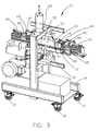
- Fig. 3 is a perspective view of an apparatus for positioning a tape preform as a layer onto a substrate during the manufacture of a layered device constructed in accordance with the principles of the present disclosure
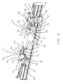
- Fig. 4 is a perspective view of a portion of the apparatus of Fig. 3 in accordance with the principles of the present disclosure
- Fig. 5 is a side view of the portion of the apparatus of Fig. 4 in accordance with the principles of the present disclosure
- Fig. 6 is a plan view of the portion of the apparatus of Figs. 4 and 5 in accordance with the principles of the present disclosure
- Fig. 7 is a perspective view of a portion of the apparatus of Fig. 3 in accordance with the principles of the present disclosure
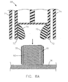
- Fig. 8A is a schematic sectional view of a bladder press in a collapsed state and a tubular substrate having a tape preform disposed on its exterior surface, in accordance with the principles of the present disclosure
- Fig. 8B is a schematic sectional view of the bladder press and substrate of Fig. 8A , showing the bladder of the bladder press disposed around the substrate, according to the principles of the present disclosure;
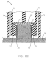
- Fig. 8C is a schematic sectional view of the bladder press and substrate of Figs. 8A and 8B , showing the bladder in an expanded state, in accordance with the principles of the present disclosure;
- Fig. 9 is a perspective view of a portion of the apparatus of Fig. 3 , having a different form of a pre-positioning device, in accordance with the principles of the present disclosure
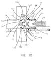
- Fig. 10 is a plan view of the portion of the apparatus of Fig. 9 ;
- Fig. 11 is a perspective view of another apparatus for positioning a tape preform as a layer onto a substrate during the manufacture of a layered device, in accordance with the principles of the present disclosure
- Fig. 12 is a perspective view of the apparatus of Fig. 11 ;
- Fig. 13 is a perspective view of yet another apparatus for positioning a tape preform as a layer onto a substrate during the manufacture of a layered device, in accordance with the principles of the present disclosure
- Fig. 14 is a perspective view of the apparatus of Fig. 13 ;
- Fig. 15 is a perspective view of still another apparatus for positioning a tape preform as a layer onto a substrate during the manufacture of a layered device, in accordance with the principles of the present disclosure
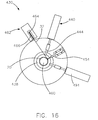
- Fig. 16 is a plan view of the apparatus of Fig. 15 ;
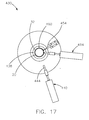
- Fig. 17 is a plan view of the apparatus of Figs. 15 and 16 ;
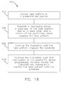
- Fig. 18 is a block diagram illustrating a method of positioning a tape preform as a layer onto a substrate during the manufacture of a layered resistive device, in accordance with the teachings of the present disclosure.
- a layered resistive device 10 is illustrated.
- the layered resistive device 10 is disposed around a target 12, to which a resistive load or heat is to be provided by the layered resistive device 10.
- the layered resistive device 10 is illustrated as being tubular and co-axially disposed, by way of example, around the target 12.
- the layered resistive device 10 and the target 12 could have other configurations; for example, the tubular resistive device 10 could have a rectangular shape or a tubular shape having a slot therein.
- the layered resistive device 10 comprises a substrate 20 upon which a number of functional layers are disposed.
- One of the functional layers is the resistive layer 18.
- the resistive layer 18 is shown wrapped around the substrate 20 in a spiral pattern; however, it should be understood that the resistive layer 18 could form any suitable pattern or be a continuous layer while remaining with the scope of the present disclosure.
- the resistive layer 18 could form a square pattern, a saw tooth pattern, a sinusoidal pattern, or any other suitable pattern.
- the resistive layer 18 could be provided having no pattern at all, and instead could be a continuous sheet.
- multiple dielectric and resistive layers 26, 18 could be used.
- the substrate 20 is formed of aluminum oxide (Al 2 O 3 ) or 430 stainless steel; however, any other suitable material may be employed depending on the specific application requirements and the material being used for the various layers.
- suitable materials include, but are not limited to, nickel-plated copper, aluminum, stainless steel, mild steels, tool steels, refractory alloys, and aluminum nitride, among others.
- the resistive layer 18 provides a heater circuit; however, it should be understood that the resistive layer 18 could provide other functions, in addition to a heater circuit or in the alternative.
- the resistive layer 18 could serve as both a heater element and a temperature sensor, a form which is disclosed in U.S. Pat. No. 7,196,295 .
- the resistive layer 18 functions as a load resistor instead of a heating element.
- a resistive layer 18 designed as a load resistor preferably has minimal inductance and is formed in a sinusoidal pattern. Such a load resistor may be used to pack other components. Load resistors may help protect certain devices by acting as a power dump for other components, to isolate the devices from the power dissipated by such other components.
- the resistive layer 18 is preferably connected to a pair of conductors 22, which are terminal pads that are further connected to a power source (not shown) through terminal wires 24. It should be understood that the conductors 22 could take forms other than terminal pads, so long as the resistive layer 18 is electrically connected to a power source in another suitable manner. In one form, the conductors 22 could be omitted and the resistive trace of the resistive layer 18 could connect directly to the terminal wires 24.
- the terminal wires 24 could be any suitable electrical lead.
- the layered resistive device 10 comprises the substrate 20 and several layers disposed on the exterior of the substrate 20. It should be understood that although the substrate 20 is shown in Figs. 1-2 , the substrate 20 is not a necessary element of the present disclosure. In some applications, the substrate 20 can be eliminated, and the layers can be applied directly to the target 12.
- a dielectric layer 26 is disposed on the surface of the substrate 20, which may be an exterior surface as shown, or any other surface of the substrate 20.
- the dielectric layer 26 is a thick film layer comprised of a single layer or multiple layers of dielectric tape in one form of the present disclosure.
- the dielectric layer 26 is disposed directly on the substrate 20, it should be understood that there could be an additional functional layer disposed between the substrate 20 and dielectric layer 26.
- a bond layer, an EMF layer, a temperature sensor layer, or any other functional layer could be disposed between the substrate 20 and the dielectric layer 26.
- the additional functional layer could be positioned above the dielectric layer 26.
- the dielectric layer 26 helps provide electrical isolation between the substrate 20 and the resistive layer 18. Therefore, the dielectric layer 26 is disposed on the substrate 20 in a thickness commensurate with the power output of the resistive layer 18. A single layer or multiple layers of dielectric tape having the desired thickness may be applied to the substrate 20; the resistive layer 18 may then be disposed on the single layer or multiple layers of dielectric tape.
- the dielectric tape Prior to processing, the dielectric tape is a flexible sheet of material that may be handled and manipulated to conform to the geometry of the substrate 20 or target 12.
- the dielectric tape generally does not exhibit adhesiveness or tackiness, and as such, may be repositioned multiple times as necessary prior to laminating the tape to the substrate 20 or target 12, or other functional layer.
- the material has dielectric properties, but these properties may not become apparent until after the dielectric layer is in its final form, i.e., after firing.
- the term "tape" (whether used for a dielectric layer, a resistive layer, a protective layer, or other functional layer) shall be construed to mean a flexible, sheet-like material that is manipulated to conform to, and to be laminated to, a substrate, a target, or other layer of the resistive device 10.
- the dielectric layer 26 may be desirable that the dielectric layer 26 have sufficient dielectric strength to provide insulation between the materials disposed on each side of the dielectric layer 26, to prevent arcing therebetween.
- thermal uniformity is often desired.
- a single layer of dielectric tape has been shown to have a desirable dielectric strength, uniform thickness, and thermal uniformity when used in a layered resistive device 10. Accordingly, the dielectric tape may be provided in the desired thickness according to application requirements.
- the type of dielectric tape chosen may depend on the substrate 20 material and the electrical output of the resistive layer 18.
- One preferred tape for a 430 stainless steel substrate, is a lead-free ceramic tape having a thickness of about 50-300 ⁇ m.
- the tape preform could contain lead.
- more than one layer of dielectric tape may be employed while remaining within the scope of the present disclosure.
- several layers of the tape preform could be applied, and these layers could be applied one at a time, or multiple layers could be applied to the substrate 20 simultaneously.
- the resistive layer 18 is disposed on the dielectric layer 26.
- the resistive layer 18 takes on a pattern, and as described above, may also be provided in a continuous layer.
- the conductors 22 are typically disposed on the dielectric layer 26 and are in electrical communication with the resistive layer 18.
- the layered resistive device 10 could be provided without conductors 22.
- the resistive layer 18 may be formed by any suitable process.
- the resistive layer 18 may be applied by any layered process such as a thick film process, a thin film process, thermal spray, or sol-gel, among others.
- layered resistive device should be construed to include devices that comprise at least one functional layer (e.g., dielectric layer 26 only, resistive layer 18 and dielectric layer 26, among others), wherein the layer is formed through application or accumulation of a material to a substrate, target, or another layer using processes associated with thick film, thin film, thermal spraying, or sol-gel, among others. These processes are also referred to as “layered processes” or “layering processes.”
- Thick film processes may include, by way of example, screen printing, spraying, rolling, and transfer printing, among others.
- Thin film processes may include, by way of example, ion plating, sputtering, chemical vapor deposition (CVD), and physical vapor deposition (PVD), among others.
- Thermal spraying processes may include, by way of example, flame spraying, plasma spraying, wire arc spraying, and HVOF (High Velocity Oxygen Fuel), among others.
- the resistive layer 18 may be formed from a single layer of tape, or multiple layers of tape, which could be applied by the methods described in further detail below.
- the resistive layer 18 could be applied as a layer or layers of tape having no trace or pattern, or it could have a pre-determined trace or pattern that is applied to a substrate 20 as a tape preform.
- the single layer or multiple layers of tape may be provided with a variable thickness such that the watt density of the resistive layer 18 can vary along the length of the trace or pattern, or across the continuous layer. It should be understood that such a variable thickness form of tape may also be provided for the other functional layers while remaining within the scope of the present disclosure.
- the protective layer 28 is disposed on the resistive layer 18 and may also cover the conductors 22, so long as the conductors 22 may be electrically connected to the lead wires ( Fig. 1 ) and/or a power source (not shown). Preferably, at least a portion of the conductors 22 are exposed through the protective layer 28.
- the protective layer 28 is preferably an insulator; however, other materials such as an electrically or thermally conductive material may also be employed according to the requirements of a specific application.
- the protective layer 28 is a dielectric material for electrical isolation and protection of the resistive layer 18 from the operating environment. As such, protective layer 28 may comprise a single layer or multiple layers of dielectric tape, similar to the dielectric layer 26 as previously set forth.
- the protective layer 28 could be applied using other thick film processes, including but not limited to screen printing, spraying, rolling, and transfer printing.
- the protective layer 28 could be applied by other layered processes such as sol-gel or thermal spray processes, among others.
- sol-gel layers are formed using processes such as dipping, spinning, or painting, among others.
- the protective layer 28 is provided as a thick film dielectric tape, while the other layers are provided using one or more layered processes.
- the dielectric layer 26 may be provided by a thick film, thin film, thermal spray, or sol-gel process.
- the resistive layer 18 would also be provided by a conventional method such as thick film, thin film, or thermal spray. In some applications, the resistive layer 18 is applied directly to the substrate 20, and the protective layer 28 is provided as a thick film dielectric tape and is disposed over the resistive layer 18.
- Dielectric tape for use with the apparatus and method of the present disclosure may be provided in the desired thickness, as described above.
- the tape preform may be pre-cut to the desired size before laminating the dielectric tape to the substrate or target.
- the tape preform may be merely perforated on a roll to allow for easy detachment of pieces of tape having the proper size.
- the tape preform could be simply provided on a roll and cut for each application.
- a positioning apparatus 30 for positioning a tape preform 32 as a layer onto a substrate 20, during the manufacture of a layered resistive device 10, is illustrated.
- the tape preform 32 could be applied as the dielectric layer 26, the resistive layer 18, or the protective layer 22.
- the tape preform 32 could be applied as any other layer that may be desirable to apply to the substrate 20.
- the positioning apparatus 30 may be provided on a cart 34 having wheels 36, such that the apparatus 30 defines a mobile unit; however, it should be understood that other configurations could also be used, without falling beyond the spirit and scope of the present disclosure.
- the positioning apparatus 30 has a positioning plate 38 for holding the substrate 20 while the tape preform 32 is positioned thereon.
- the positioning plate 38 may be a movable platform configured to translate the substrate 20. More particularly, the positioning plate 38 may be connected to a translating member 39, which is configured to translate the positioning plate 38.
- the positioning plate 38 is illustrated isolated from the rest of the positioning apparatus 30, and it should be understood that the positioning plate 38 need not be movable, and in some forms, the positioning plate 38 and components attached thereto could constitute the entirety of the positioning apparatus 30.
- the positioning apparatus 30 has at least one positioning member, such as a grabber arm 40, and in one form, a plurality of grabber arms 40 as shown.
- a positioning member such as a grabber arm 40
- a plurality of grabber arms 40 as shown.
- a set of two of grabber arms 40 is shown and described herein, it should be understood that, in some forms, a single grabber arm 40 could be used.
- the grabber arm 40 defines a proximal end portion 42, a distal end portion 44, and a contoured inner profile surface 45 extending between the proximal end portion 42 and the distal end portion 44.
- the contoured inner profile surfaces 45 of the grabber arms 40 are configured to correspond with the shape of the substrate 20, which may be cylindrical as illustrated herein. As an alternative to cylindrical shapes, the substrate 20 and the contoured inner profile surfaces 45 of the grabber arms 40 may have other corresponding shapes. Moreover, in some forms, the contoured inner profile surface 45 need not have a shape similar to that of the substrate 20.
- the proximal end portion 42 is pivotally attached to a base member 46 via a pivoting member, which allows the grabber arms 40 to partially rotate with respect to the base member 46.
- the grabber arms 40 follow the contour of the substrate 20 as they move therearound, which is described in further detail below.
- two base members 46 are located at each end of the positioning plate 38.
- Each base member 46 has a set of two grabber arms 40 pivotally connected thereto at the proximal end portions 42 of the grabber arms 40.
- the grabber arms 40 are also connected to opposed translation devices 48, which are attached to the base members 46.
- a translation device 48 is located on each side of the base members 46, and each translation device 48 is secured to the proximal end portion 42 of one of the grabber arms 40.
- Each translation device 48 may include, by way of example, an outer cylindrical member 50 that surrounds an inner cylindrical member 52.
- the inner cylindrical member 52 is configured to move outward from the outer cylindrical member 50 upon actuation to translate a portion of the grabber arm 40, causing the grabber arm 40 to pivot with respect to the base member 46 via its pivoting member.
- a contact member 54 is connected to the distal ends 44 of the pair of grabber arms 40. More particularly, the distal ends 44 include support members 56, and the contact member 54 engages the support members 56 and a dowel pin 58 that is connected to the base member 46.
- the support members 56 may be pivotally connected to the grabber arms 40.
- the contact member 54 is preferably an elastic band that is secured to the support members 56 and the dowel pin 58 by being disposed around the support members 56 and the dowel pin 58.
- the substrate 20 is placed on a substrate mandrel 60.
- one substrate mandrel 60 is provided for use with each base member 46 and each pair of grabber arms 40.
- a pre-positioning device 62 including a pair of holding pins 64 holds the tape preform 32 in place at a predetermined distance from the substrate 20, which is located around the substrate mandrel 60, prior to positioning the tape preform 32 onto the substrate 20.
- the predetermined distance could be equal to zero, such that the tape preform 32 contacts the substrate 20 when the substrate 20 is located on the substrate mandrel 60 and tape preform 32 is held by the pre-positioning device 62 (See Fig. 6 ).
- the pre-positioning device 62 is offset a predetermined distance from the substrate 20.
- pre-positioning device 62 is shown and described as having holding pins 64, it should be understood that the pre-positioning device could have any other holding member.
- square-shaped or other holding members instead of holding pins 64, could be used.
- the holding pins 64 of the pre-positioning device 62 define cutouts 66 for placement of the tape preform 32; however, it should be understood that the pre-positioning device 62 could have a variety of other configurations.
- the pre-positioning device 62 and the substrate mandrel 60 are mounted to the positioning plate 38, which is in turn mounted to the translating member 39.
- the pre-positioning device 62 could include a vacuum source to provide a pulling force to the tape preform 32, to hold the tape preform 32 in place in the cutouts 66 of the holding pins 64.
- the vacuum source could include, by way of example, a manifold having apertures and/or vacuum hoses disposed on the base member 46 or the positioning plate 38 to apply a vacuum to the tape preform 32.
- the contact member 54 is operable with a pair of the grabber arms 40 to engage the tape preform 32 against the substrate 20, when the substrate 20 is disposed proximate the substrate mandrel 60.
- the grabber arms 40 pivot at their proximal end portions 42.
- the base member 46 is translated toward the substrate 20, and this translation in conjunction with the translation provided by the translation devices 48 causes the grabber arms 40 to be translated around the substrate 20 and the contact member 54 to engage the tape preform 32 against the substrate 20.
- the translation of the grabber arms 40 around the substrate 20 occurs by virtue of both the translations provided by the translation devices 48 secured to the grabber arms, and by virtue of the translation provided by the additional translation device 49 that is secured to the base member 46.
- the contoured inner profile surfaces 45 of the grabber arms'40 allow the grabber arms 40 to move the support members 56 around and in contact with the periphery of the substrate 20 through the contact member 54 to press the tape preform 32 against the periphery of the substrate 20.
- the substrate mandrels 60 are mounted on the positioning plate 38, which may be secured to the translating member 39.
- the translating member 39 is configured to translate the positioning plate 38 to align the substrate mandrels 60 with a press 68 that is vertically positioned with respect to the substrate mandrels 60 (See Figs. 3 and 7 ).
- the positioning apparatus 30 may also have a controller to control the translating member 39 of the positioning plate 38, for example, to move the substrate mandrels 60 between starting positions and positions aligned with the press 68.
- the controller could be configured to move the positioning plate 38 back and forth to position each substrate mandrel 60 under the press 68 in a sequential manner.
- the controller could also be configured to communicate with the translation devices 48, 49 that position the grabber arms 40 and contact members 54.
- the controller could be configured to actuate each of the translation devices 48, 49 to move the grabber arms 40 and contact members 54.
- the controller could actuate the translation device 49 to move the base member 46 with respect to the positioning plate 38. Because the grabber arms 40 are attached to the base member 46, such actuation of the translation device 49 would have the effect of moving the grabber arms 40 toward the substrate 20 and moving the distal ends 44 past the substrate 20.
- the controller could also actuate the translation devices 48 to pivot the grabber arms 40 at their pivot members to allow the grabber arms 40 and contact member 54 to position the tape 32 against the substrate 20 as the grabber arms 40 move around the substrate 20.
- the controller could actuate simultaneously both the translation devices 48 attached to the proximal ends 42 of the grabber arms 40 and the translation device 49 attached to the base member 46. The effect of the simultaneous actuation would be to move the grabber arms 40 toward and around the substrate 20, while the positioning members 56 of the distal ends 44 press the contact member 54 against the tape 32 and the substrate 20.
- the press 68 includes a bladder 70, which, in one form, is substantially cylindrical such that it may be lowered toward and around the substrate 20 and tape preform 32, which are located around the mandrel 60.
- the bladder 70 is movable between an expanded state and a collapsed state.
- the press 68 including the bladder 70, is advanced toward the substrate 20, tape preform 32, and mandrel 60.
- the substrate 20, tape preform 32, and mandrel are received within the center of the cylindrical bladder 70 of the press 68.
- the bladder 70 is preferably in the collapsed state such that it may fit between the substrate 20 and the press wall 72 and the substrate 20.
- a fluid medium is released or inserted into the bladder 70 to inflate the bladder 70 into the expanded state.
- the fluid medium may comprise water, air, or any other suitable medium.
- the bladder 70 When in the expanded state and inserted around the substrate 20 and tape preform 32, the bladder 70 is tightly pressed up against the tape preform 32 and the outer surface of the substrate 20. In other words, the bladder 70 engages the tape preform 32 to press it against the outer surface of the substrate 20, in the expanded state.
- the grabber arms 40 and contact member 54 remain in contact with the tape preform until such inflation of the bladder 70 to ensure that the tape preform 32 remains uniformly pressed around the substrate 20.
- a pressurized vessel 74 may be part of the press 68 and may be lowered to surround the press wall 72 and contact the positioning plate 38; however, it should be understood that the pressurized vessel 74 could have any suitable configuration.
- the press 68 and the substrate 20 could simply be moved into a pressurized vessel, or the room surrounding the press 68 and the substrate 20 could be an isostatic, hydrostatic, or hydraulic press.
- a predetermined cycle of pressure, temperature, and time is applied to the substrate 20 and tape preform 32 to laminate or adhere the tape preform 32 to the substrate 20.
- the predetermined cycle of pressure, temperature, and time is a single cycle.
- the bladder 70 helps facilitate a uniform application of pressure to the outer surface of the tape preform 32.
- the bladder 70 is preferably maintained in the expanded state through the predetermined cycle of pressure, temperature, and time. Such a uniform application of pressure causes the tape preform 32 to be laminated to the substrate 20 with a substantially uniform thickness and adhesion.
- the cycle of pressure, temperature, and time may be applied using an isostatic press, or the cycle may be applied in another suitable manner.
- the press 68 could be an isostatic press.
- the press 68 could be a hydraulic or hydrostatic press.
- An isostatic press subjects a component to both temperature and isostatic pressure in a high pressure containment vessel.
- the medium used to apply the pressure could be an inert gas, such as Argon, a liquid, such as water, or any other suitable medium.
- the pressure being isostatic it is applied to the component from all directions.
- the pressure to be applied is in the range of about 50 to about 10,000 psi (pounds per square inch)
- the temperature to be applied is in the range of about 40 to about 110 °C
- the amount of time in the cycle for applying the temperature and pressure is in the range of about 5 seconds to about 10 minutes.
- the particular pressure, temperature, and time to be applied depend on the size of the parts and the characteristics of the materials.
- the press 68 is raised away from the substrate 20. Thereafter, the substrate 20 with the attached tape preform 32 is preferably fired in a furnace (not shown). As referred to herein, the firing process could comprise multiple stages, such as, by way of example, a separate burn out and firing process. One or more drying steps could also be used.
- the translating member 39 of the positioning apparatus 30 is configured to translate the positioning plate 38 to move the pressed substrate 20 including the tape preform 32 laminated thereto away from the press 68 and to simultaneously move another substrate 20 and tape preform 32 located on the other side of the positioning plate 38 toward the press 68.
- the translating member 39 of the positioning plate 38 sequentially moves each substrate 20 and tape preform 32 under the press 68 such that the press 68 may be sequentially placed over each substrate 20 and tape preform 32, each tape preform 32 being held around each substrate 20 by the sets of grabber arms 40 and contact members 54 located at each end of the positioning plate 38 on the base members 46, as hereinbefore described.
- the tape preform 132 is part of a continuous stock of tape preform 180, in other words, a roll of tape.
- the pre-positioning device 162 includes reels 182 that feed the continuous stock of tape preform 132 therethrough.
- a cutting device 184 such as a knife, may be used to cut the tape preform 132 to a predetermined size. The cutting device 184 could be used to cut the tape preform 132 either before, during, or after the tape preform 132 is positioned on the substrate 20.
- the tape preform 132 could be provided with pre-cut portions, such as perforations, which could be configured to allow the preform tape 132 to be automatically torn off, or to allow the preform tape 132 to be more easily cut by the cutting device 184.
- the positioning apparatus 230 includes a contact member 254 configured to engage a tape preform 32 against a substrate 20, which is in the form of a cylindrical rod.
- the contact member 254 could include an inner cylindrical rod 286 that is movable with respect to an outer cylindrical rod 288.
- the tape preform 32 may be held by a pre-positioning device 262, which may be similar to any of the pre-positioning devices 62, 162 hereinbefore described.
- the pre-positioning device 262 could include holding pins 264 defining cutouts 266 for holding the tape preform 32.
- the positioning apparatus 230 may be designed such that the substrate 20 is configured to be pushed toward the contact member 254 to make contact between the contact member 254 and the substrate 20, with the tape preform 32 in between the contact member 254 and the substrate 20.
- the positioning device 230 may be designed such that the contact member 254 advances forward to press the tape preform 32 against the substrate 20.
- the substrate 20 remains stationary, and it could be positioned on a stationary mandrel 260, such as a mandrel similar to the mandrels 60 of Figs. 3-7 , by way of example.
- the contact member 254 could be secured to a base member 246, which could be connected to a translation device configured to translate the base member 246, the contact member 254, and the positioning members 240 (described below) toward the substrate 20.
- the contact member 254 presses the tape preform 32 against the substrate 20.
- the positioning members 240 are translated around the substrate 20 to engage the tape preform 32 against the substrate 20.
- the positioning members 240 may be secured to the base member 246 via pivot members 290 located proximal ends 242 of the positioning members 240.
- the pivot members 290 could be connected to biasing members, such as springs (not shown) to bias the distal ends 244 of the positioning members 240 toward each other.
- biasing members such as springs (not shown) to bias the distal ends 244 of the positioning members 240 toward each other.
- the positioning members 240 may be advanced with respect to the substrate 20 either by the substrate 20 being pushed toward the contact member 254 (the inner cylinder 286 could be configured to recede into the outer cylinder 288 against a spring force as the substrate 20 is moved toward it), and/or by the base member 246 being translated toward the substrate 20, for example, with the use of a translating member (not shown).
- the substrate 20 and tape preform 32 may be inserted into a press, such as the press 68 hereinbefore described, to laminate or adhere the tape preform 32 to the substrate 20.
- FIG. 13 yet another variation of an apparatus for positioning a tape preform against a substrate is illustrated and generally designated at 330.
- a substrate 20 is held stationary by a substrate mandrel 360 located on a positioning plate 338.
- the positioning apparatus 330 includes a set of positioning members 340, each of which include a proximal end portion 342 that is pivotally connected to a base member 346, and a distal end portion 344. Each distal end portion 344 includes a contact member 354 pivotally connected thereto.
- an elastic contact member (not shown) could be disposed around the contact members 354 and a dowel pin (not shown) to provide additional support to hold the tape preform 32 against the substrate 20.
- the base member 346 is configured to be translated toward the substrate 20 and the tape preform 32, such that the contact members 354 press the tape preform 32 against the substrate as they make contact with the tape preform 32 and the substrate 20. As the base member 346 is further translated toward the substrate 20, the contact members 354 press the tape preform 32 around and against the periphery of the substrate 20. After pressing the tape preform 32 around the periphery of the substrate 20, the contact members 354 contact each other, and the substrate 20 and tape preform 32 are held within a contoured inner profile 392 of the positioning members 340.
- the contoured inner profile 392 is shaped so as to contact the tape preform 32 around the substantial majority of the periphery, or in some forms, the entire periphery of the substrate 20. Thus, the contoured inner profile 392 provides additional support to hold the tape preform 32 against the substrate 20 until the tape preform 32 is adhered to the substrate 20.
- the tape preform 32 is adhered or laminated to the substrate 20 in any suitable manner, such as those hereinbefore described.
- a press 68 could be used.
- the apparatus 430 includes a positioning plate 438, which has a substrate mandrel 460 secured thereto for holding a substrate 20.
- a pre-positioning device 462 is provided to hold a piece of tape preform 32 in place prior to the tape preform 32 being applied to the substrate 20.
- the pre-positioning device 462 includes a holding member 464 defining a cutout 466 to hold the tape preform 32.
- a first end of the tape preform 32 is held against the substrate 20, through the use a first contact member 454.
- a distal end portion 444 of a positioning member such as a swiper arm 440, is then advanced into contact with the tape preform 32 to press the tape preform 32 against the substrate 20.
- the pre-positioning device 462 may then be advanced away to allow space for the swiper arm 440 to rotate around the substrate 20.
- the swiper arm 440 is rotated around the substrate 20 to engage the tape preform 32 with the substrate 20 around the periphery of the substrate 20.
- a second contact member 494 is advanced into contact with the tape preform 32 and the substrate 20 to hold the second end of the tape preform 32 against the substrate 20.
- the swiper arm 440 is then advanced away from the substrate 20 and the tape preform 32.
- the substrate 20 and tape preform 32 are received into a press, such as the press 68 hereinbefore described.
- the substrate 20 and tape preform 32 may otherwise be subjected to a cycle of pressure, temperature, and time to adhere or laminate the tape preform 32 to the substrate 20.
- the first and second contact members 454, 494 may be released and withdrawn from the substrate 20 and the tape preform 32.
- the method 500 includes a step 502 of locating the tape preform in a predetermined position. This step 502 may include the use of a pre-positioning device 62, 162, 262, 362, 462, as hereinbefore described.
- the method 500 also includes a step 504 of translating at least one of the following relative to each other: a positioning device, the substrate, and the tape preform. The translation occurs until a portion of the positioning device engages the tape preform.
- the positioning device could be provided as a grabber arm 40, a swiper arm 440, or any other suitable positioning device, such as the other positioning devices 240, 340 described herein, by way of example.
- the method 500 further includes a step 506 of continuing the translation until the tape preform engages the substrate and a step 508 of continuing the translation such that components of the positioning device progressively translate around the substrate and subsequently position the tape preform onto the substrate.
- the method 500 may also include providing the positioning device such that the portion of the positioning device that first engages the tape preform and the components of the positioning device that progressively translate around the substrate move dependently with each other.
- the positioning device such that the portion of the positioning device that first engages the tape preform and the components of the positioning device that progressively translate around the substrate move dependently with each other.
- the method 500 may include providing the substrate as translatable with the positioning device.
- the substrate 20 is located on a substrate mandrel 60, which is translatable.
- the entire positioning device 30 is provided on a movable cart.
- the method 500 may further include providing the components of the positioning device that progressively translate around the substrate as being pivotable at one end and as moving the portion of the positioning device that first engages the tape preform at another end, while progressively translating around the substrate.
- the method 500 may include translating a press onto the tape preform and the substrate while retracting the positioning device away from the substrate. Such translation may be accomplished utilizing a controller.
- the positioning device, the substrate, the tape preform, or other components may be translated relative to each other using a controller.
- the tape preform layer on the substrate 20 may be combined with other layers.
- the resistive layer 18 may be added to the dielectric tape layer 26 after the dielectric tape layer 26 is laminated to the substrate 20.
- the resistive layer 18 may be formed on the dielectric tape layer 26 using a layered process such as thin film, thick film, thermal spray, or sol-gel, all of which have been described above.
- a protective layer 28 may then be formed on the resistive layer by a layered process such as thin film, thick film, thermal spray, or sol-gel.
- the protective layer 28 may be a thick film dielectric tape, which may be applied by the method 500 and apparatuses 30, 230, 330, 430 described herein.
- the protective layer 28 may be a dielectric tape layer that is laminated to the resistive layer 18.
- the resistive layer 18 may also or alternatively be applied as a preform tape 32.
- the resistive layer 18, the protective layer 28, and/or conductors 22 may be preformed on the dielectric tape layer 26.
- the resistive layer 18, protective layer 28, and/or conductors 22 could be formed on the dielectric tape layer 26 before it is laminated to a substrate 20 or target.
- notches, cut-outs, or slots could also be pre-cut into or through the dielectric tape layer(s) 26 and any other functional layers attached thereto.
Landscapes
- Engineering & Computer Science (AREA)
- Manufacturing & Machinery (AREA)
- Microelectronics & Electronic Packaging (AREA)
- Laminated Bodies (AREA)
- Apparatuses And Processes For Manufacturing Resistors (AREA)
- Moulding By Coating Moulds (AREA)
Claims (19)
- Vorrichtung (30), um eine Bandvorform (32) während der Herstellung eines geschichteten Widerstandsgeräts (10) als eine Schicht auf einem Substrat (20) zu positionieren, welche aufweist: mindestens ein Positionierelement (38), wobei das Positionierelement (38) einen proximalen Endabschnitt und einen distalen Endabschnitt festlegt; und ein Kontaktelement (54), das angepasst ist, die Bandvorform (32) gegen das Substrat (20) zur Anlage zu bringen, wobei das Kontaktelement (54) und der distale Endabschnitt des Positionierelements (38) ausgestaltet sind, die Bandvorform (32) auf dem Substrat (20) zu positionieren.
- Vorrichtung (30) nach Anspruch 1, ferner ein Basiselement (46) aufweisend, wobei das mindestens eine Positionierelement (38) über eine Vielzahl von Greifarmen (40) verfügt, wobei die Greifarme (40) einen proximalen Endabschnitt und einen distalen Endabschnitt festlegen, wobei der proximale Endabschnitt an dem Basiselement (46) angebracht ist und jeder Greifarm (40) ein Stützelement (56) nahe dem distalen Endabschnitt und eine geschwungene Innenprofiloberfläche (45), die sich zwischen dem proximalen Endabschnitt und dem distalen Endabschnitt erstreckt, aufweist und wobei das Kontaktelement (54) ein elastisches Kontaktelement (54) ist, das an dem Basiselement (46) befestigt und um die Stützelemente (56) der Greifarme (40) herum angeordnet ist.
- Vorrichtung (30) nach einem der vorangegangenen Ansprüche, ferner eine Vorpositioniervorrichtung (62) aufweisend, die angepasst ist, die Bandvorform (32) vor dem Positionieren auf dem Substrat (20) an ihrem Platz zu halten.
- Vorrichtung (30) nach einem der vorangegangenen Ansprüche, wobei die Vorpositioniervorrichtung (62) gegenüberliegende Halteelemente, die Ausschnitte (66) zum Platzieren der Bandvorform (32) festlegen, aufweist, wobei vorzugsweise die Vorpositioniervorrichtung (62) Rollen (182), die einen ununterbrochenen Vorrat an Bandvorform (180) zuführen, aufweist.
- Vorrichtung (30) nach einem der vorangegangenen Ansprüche, ferner ein Verschiebeelement (39) aufweisend, wobei die Vorpositionierelemente (62) und ein Substratdorn (60) an dem Verschiebeelement (39) oder einer mit dem Verschiebeelement (39) verbundenen Positionierplatte (38) angebracht sind.
- Vorrichtung (30) nach einem der vorangegangenen Ansprüche, wobei die gegenüberliegenden Greifarme (40) schwenkbar an dem Basiselement (46) angebracht sind, wobei vorzugsweise die geschwungenen Innenprofiloberflächen (45) der Greifarme (40) ausgestaltet sind, einer Form des Substrats (20) zu entsprechen, wobei das Positionierelement (38) einen Mitnehmerarm aufweist.
- Vorrichtung (30) nach einem der vorangegangenen Ansprüche, ferner gegenüberliegende Verschiebevorrichtungen (48) aufweisend, die an den proximalen Endabschnitten der gegenüberliegenden Greifarme (40) befestigt und ausgestaltet sind, die Greifarme (40) auf dem Basiselement (46) zu schwenken.
- Vorrichtung (30) nach einem der vorangegangenen Ansprüche, ferner eine Verschiebevorrichtung (48) aufweisend, die an dem Basiselement (46) befestigt und ausgestaltet ist, das Basiselement (46) relativ zu dem Substrat (20) zu verschieben.
- Vorrichtung (30) nach einem der vorangegangenen Ansprüche, ferner einen an dem Basiselement (46) befestigten Passstift (58) aufweisend, wobei das elastische Kontaktelement (54) an dem Basiselement (46) befestigt ist, indem es um den Passstift (58) herum angeordnet ist.
- Vorrichtung (30) nach einem der vorangegangenen Ansprüche, wobei die Vorpositioniervorrichtung (62) in einem vorgegebenen Abstand von dem Substrat (20) versetzt ist und vorzugsweise die Vorpositioniervorrichtung (62) eine Vakuumquelle aufweist.
- Vorrichtung (30) nach einem der vorangegangenen Ansprüche, ferner eine Schneidvorrichtung (184) aufweisend, die angepasst ist, die Bandvorform (32) vor dem Positionieren der Bandvorform (32) auf dem Substrat (20) auf eine vorgegebene Größe zuzuschneiden.
- Vorrichtung (30) nach einem der vorangegangenen Ansprüche, ferner eine Presse (68) aufweisend, die nahe den Greifarmen (40) und dem elastischen Kontaktelement (54) angeordnet und angepasst ist, nacheinander um die Bandvorform (32) und das Substrat (20) herum angeordnet zu werden, nachdem die Greifarme (40) und das elastische Kontaktelement (54) die Bandvorform (32) auf dem Substrat (20) positioniert haben.
- Vorrichtung (30) nach Anspruch 1, ferner aufweisend: mindestens einen ersten Greifarm (40), wobei der erste Greifarm (40) einen proximalen Endabschnitt und einen distalen Endabschnitt festlegt und der erste Greifarm (40) eine geschwungene Innenprofiloberfläche (45), die sich zwischen dem proximalen Endabschnitt und dem distalen Endabschnitt erstreckt, aufweist; einen ersten Substratdorn (60); ein erstes Kontaktelement (54), das mit dem ersten Greifarm (40) betreibbar und angepasst ist, eine Bandvorform (32) gegen ein erstes Substrat (20) zur Anlage zu bringen, wobei das erste Substrat (20) nahe dem ersten Substratdorn (60) angeordnet ist; mindestens einen zweiten Greifarm (40), wobei der zweite Greifarm (40) einen proximalen Endabschnitt und einen distalen Endabschnitt festlegt und der zweite Greifarm (40) eine geschwungene Innenprofiloberfläche (45), die sich zwischen dem proximalen Endabschnitt und dem distalen Endabschnitt erstreckt, aufweist; einen zweiten Substratdorn (60); ein zweites Kontaktelement (54), das mit dem zweiten Greifarm (40) betreibbar und angepasst ist, eine Bandvorform (32) gegen ein zweites Substrat (20) zur Anlage zu bringen, wobei das zweite Substrat (20) nahe dem zweiten Substratdorn (60) angeordnet ist, wobei die Kontaktelemente (54) und die geschwungenen Innenprofiloberflächen (45) der Greifarme (40) ausgestaltet sind, die Bandvorformen (32) nacheinander auf den Substraten (20) zu positionieren; und mindestens eine Presse (68), die nahe den Greifarmen (40) und den Kontaktelementen (54) angeordnet und angepasst ist, nacheinander um jede der Bandvorformen (32) und jedes der Substrate (20) herum angeordnet zu werden, nachdem die Greifarme (40) und Kontaktelemente (54) die Bandvorformen (32) auf den Substraten (20) positioniert haben.
- Vorrichtung (30) nach einem der vorangegangenen Ansprüche, wobei die Vorrichtung (30) eine mobile Einheit festlegt.
- Verfahren zum Positionieren einer Bandvorform als eine Schicht auf einem Substrat mit einer Vorrichtung nach einem der Ansprüche 1 bis 14 während der Herstellung einer geschichteten Widerstandsvorrichtung, das beinhaltet: Anordnen der Bandvorform in einer vorgegebenen Position; Verschieben mindestens einer Positioniervorrichtung, des Substrats oder der Bandvorform relativ zueinander, bis ein Abschnitt der Positioniervorrichtung sich an die Bandvorform anlegt; Fortsetzen der Verschiebung, bis die Bandvorform sich an das Substrat anlegt; und Fortsetzen der Verschiebung in der Weise, dass Komponenten der Positioniervorrichtung die Bandvorform fortschreitend um das Substrat herum verschieben und es anschließend auf dem Substrat positionieren.
- Verfahren nach Anspruch 15, wobei der Abschnitt der Positioniervorrichtung, der sich zuerst an die Bandvorform anlegt, und die Komponenten der Positioniervorrichtung, die eine fortschreitende Verschiebung um das Substrat herum durchführen, sich abhängig voneinander bewegen, vorzugsweise mit Verschiebung des Bandes unter Verwendung einer Steuerung.
- Verfahren nach Anspruch 15, wobei das Substrat mit der Positioniervorrichtung verschiebbar ist, vorzugsweise mit Verschiebung unter Verwendung einer Steuerung.
- Verfahren nach Anspruch 15, wobei die Komponenten der Positioniervorrichtung, die eine fortschreitende Verschiebung um das Substrat herum durchführen, an einem Ende schwenkbar sind und den Abschnitt der Positioniervorrichtung, der sich zuerst an die Bandvorform anlegt, an einem anderen Ende bewegen, während sie eine fortschreitende Verschiebung um das Substrat herum durchführen, vorzugsweise mit Verschiebung der Positioniervorrichtung unter Verwendung einer Steuerung.
- Verfahren nach Anspruch 15, ferner beinhaltend das Verschieben einer Presse auf die Bandvorform und das Substrat, während die Positioniervorrichtung von dem Substrat zurückgezogen wird.
Applications Claiming Priority (2)
| Application Number | Priority Date | Filing Date | Title |
|---|---|---|---|
| US12/098,827 US8061402B2 (en) | 2008-04-07 | 2008-04-07 | Method and apparatus for positioning layers within a layered heater system |
| PCT/US2009/039250 WO2009126503A1 (en) | 2008-04-07 | 2009-04-02 | Method and apparatus for positioning layers within a layered heater system |
Publications (2)
| Publication Number | Publication Date |
|---|---|
| EP2272071A1 EP2272071A1 (de) | 2011-01-12 |
| EP2272071B1 true EP2272071B1 (de) | 2013-12-11 |
Family
ID=40811180
Family Applications (1)
| Application Number | Title | Priority Date | Filing Date |
|---|---|---|---|
| EP09730687.2A Not-in-force EP2272071B1 (de) | 2008-04-07 | 2009-04-02 | Verfahren und vorrichtung um schichten in einen beschichteten heizsystem zu positionieren |
Country Status (7)
| Country | Link |
|---|---|
| US (2) | US8061402B2 (de) |
| EP (1) | EP2272071B1 (de) |
| JP (1) | JP5214022B2 (de) |
| CN (1) | CN102047354B (de) |
| CA (1) | CA2720741C (de) |
| MX (1) | MX2010011073A (de) |
| WO (1) | WO2009126503A1 (de) |
Families Citing this family (3)
| Publication number | Priority date | Publication date | Assignee | Title |
|---|---|---|---|---|
| CN101911828B (zh) * | 2007-11-16 | 2014-02-26 | 沃特洛电气制造公司 | 具有防水层的套筒加热器及其制造方法 |
| WO2009117408A1 (en) * | 2008-03-18 | 2009-09-24 | Watlow Electric Manufacturing Company | Layered heater system with honeycomb core structure |
| JP2022051177A (ja) * | 2020-09-18 | 2022-03-31 | 秀夫 谷口 | 3次元プリンタ用のホットエンド、3次元プリンタ、及び加熱手段 |
Family Cites Families (42)
| Publication number | Priority date | Publication date | Assignee | Title |
|---|---|---|---|---|
| US614689A (en) * | 1898-11-22 | Bottle | ||
| US1641045A (en) * | 1925-01-10 | 1927-08-30 | O & J Machine Company | Spotting and labeling machine |
| US2119371A (en) * | 1936-07-16 | 1938-05-31 | New Jersey Machine Corp | Machine for applying labels |
| US2597431A (en) * | 1949-09-05 | 1952-05-20 | Crown Cork Company Ltd | Labeling machine |
| US3188716A (en) * | 1961-11-10 | 1965-06-15 | Western Electric Co | Methods of making capacitors |
| GB1132794A (en) | 1967-04-04 | 1968-11-06 | Matsushita Electric Industrial Co Ltd | Improvements in or relating to the manufacture of film-type resistors |
| FR1593353A (de) * | 1968-11-25 | 1970-05-25 | ||
| US3648218A (en) | 1971-04-12 | 1972-03-07 | David Kellerman | Wound resistor arrangement |
| US3845443A (en) | 1972-06-14 | 1974-10-29 | Bailey Meter Co | Thin film resistance thermometer |
| US3806098A (en) | 1972-07-11 | 1974-04-23 | Xodar Corp | Vertical aerating system |
| US3880609A (en) | 1972-12-14 | 1975-04-29 | Richard E Caddock | Method and apparatus for manufacturing cylindrical resistors by thick-film silk-screening |
| AU475305B2 (en) * | 1973-12-14 | 1976-08-19 | Caddock, Richard Elliot | Method and apparatus for manufacturing cylindrical resistors by thick-film silk-screening |
| DE2450551C2 (de) | 1974-10-24 | 1977-01-13 | Heraeus Gmbh W C | Elektrischer messwiderstand fuer ein widerstandsthermometer und verfahren zu seiner herstellung |
| US4072921A (en) | 1976-04-27 | 1978-02-07 | Amf Incorporated | Low inductance precision resistor deposited on an adhesive backing and wound on a bobbin |
| JPS56106159A (en) | 1980-01-28 | 1981-08-24 | Hitachi Ltd | Production of sensor for detecting flow speed and flow rate |
| JPS57178877A (en) | 1981-04-30 | 1982-11-04 | Oki Electric Ind Co Ltd | Thermal head |
| JPS6213285A (ja) | 1985-06-28 | 1987-01-22 | Hitachi Electronics Eng Co Ltd | 厚膜モジユ−ル基板用ロ−ダ・アンロ−ダ |
| US4866411A (en) * | 1988-03-25 | 1989-09-12 | Caddock Richard E | Film-type cylindrical resistor, and method of making it |
| CA2018113A1 (en) | 1989-08-07 | 1991-02-07 | John Trublowski | Layered thick film resistors and method of producing the same |
| US4980014A (en) * | 1989-12-21 | 1990-12-25 | Owens-Brockway Glass Container Inc. | Apparatus for applying wrap-around labels to containers |
| EP0720416B1 (de) | 1994-12-29 | 2004-03-24 | Robert Bosch Gmbh | Keramische Heizeinrichtung, Verfahren zu deren Herstellung und deren Verwendung |
| JP3373973B2 (ja) | 1995-05-12 | 2003-02-04 | ブラザー工業株式会社 | 定着用加熱ローラ |
| EP0848894B1 (de) | 1996-07-15 | 1999-01-27 | Koninklijke Philips Electronics N.V. | Heizelement |
| GB2316848B (en) | 1996-08-27 | 2000-10-04 | Strix Ltd | Electric heaters |
| JPH11238571A (ja) * | 1998-02-23 | 1999-08-31 | Sumitomo Metal Electronics Devices Inc | セラミックヒータの製造方法および製造装置 |
| GB2338632A (en) | 1998-06-16 | 1999-12-22 | Pifco Ltd | Metal sheathed planar element: Edge connector with shutter |
| KR100371828B1 (ko) | 1998-08-04 | 2003-02-12 | 다이켄카가쿠 코교 가부시키가이샤 | 퀴크 히트 로울러 |
| JP3694408B2 (ja) * | 1998-10-02 | 2005-09-14 | 日本特殊陶業株式会社 | セラミックスヒータの製造方法 |
| US5973296A (en) | 1998-10-20 | 1999-10-26 | Watlow Electric Manufacturing Company | Thick film heater for injection mold runner nozzle |
| JP3601993B2 (ja) | 1999-02-26 | 2004-12-15 | 三菱電機株式会社 | 熱型センサおよびその製造方法 |
| JP3670516B2 (ja) | 1999-05-26 | 2005-07-13 | シャープ株式会社 | ロール状ヒータ及びロール状ヒータを用いた定着装置 |
| US6222166B1 (en) | 1999-08-09 | 2001-04-24 | Watlow Electric Manufacturing Co. | Aluminum substrate thick film heater |
| TW426217U (en) | 1999-10-12 | 2001-03-11 | Gen Semiconductor Of Taiwan Lt | Resistive sheet adhering device |
| US7241131B1 (en) | 2000-06-19 | 2007-07-10 | Husky Injection Molding Systems Ltd. | Thick film heater apparatus |
| US7304276B2 (en) | 2001-06-21 | 2007-12-04 | Watlow Electric Manufacturing Company | Thick film heater integrated with low temperature components and method of making the same |
| US6652906B1 (en) | 2002-11-19 | 2003-11-25 | Hitachi Global Storage Technologies Netherlands B.V. | Fabrication of a magnetoresistance sensor structure having a spacer layer produced by multiple deposition and oxidation steps |
| US7196295B2 (en) | 2003-11-21 | 2007-03-27 | Watlow Electric Manufacturing Company | Two-wire layered heater system |
| US8680443B2 (en) | 2004-01-06 | 2014-03-25 | Watlow Electric Manufacturing Company | Combined material layering technologies for electric heaters |
| US8536496B2 (en) | 2004-09-15 | 2013-09-17 | Watlow Electric Manufacturing Company | Adaptable layered heater system |
| TWI374682B (en) * | 2006-07-20 | 2012-10-11 | Watlow Electric Mfg | Layered heater system having conductive overlays |
| US8557082B2 (en) | 2007-07-18 | 2013-10-15 | Watlow Electric Manufacturing Company | Reduced cycle time manufacturing processes for thick film resistive devices |
| US8089337B2 (en) | 2007-07-18 | 2012-01-03 | Watlow Electric Manufacturing Company | Thick film layered resistive device employing a dielectric tape |
-
2008
- 2008-04-07 US US12/098,827 patent/US8061402B2/en active Active
-
2009
- 2009-04-02 CA CA2720741A patent/CA2720741C/en active Active
- 2009-04-02 EP EP09730687.2A patent/EP2272071B1/de not_active Not-in-force
- 2009-04-02 CN CN200980120159.4A patent/CN102047354B/zh not_active Expired - Fee Related
- 2009-04-02 MX MX2010011073A patent/MX2010011073A/es active IP Right Grant
- 2009-04-02 WO PCT/US2009/039250 patent/WO2009126503A1/en not_active Ceased
- 2009-04-02 JP JP2011504066A patent/JP5214022B2/ja not_active Expired - Fee Related
-
2010
- 2010-08-25 US US12/868,456 patent/US8070899B2/en active Active
Also Published As
| Publication number | Publication date |
|---|---|
| US8061402B2 (en) | 2011-11-22 |
| US8070899B2 (en) | 2011-12-06 |
| US20100319186A1 (en) | 2010-12-23 |
| EP2272071A1 (de) | 2011-01-12 |
| US20090250173A1 (en) | 2009-10-08 |
| JP5214022B2 (ja) | 2013-06-19 |
| JP2011518435A (ja) | 2011-06-23 |
| CN102047354B (zh) | 2014-09-03 |
| MX2010011073A (es) | 2010-12-14 |
| CA2720741A1 (en) | 2009-10-15 |
| CA2720741C (en) | 2013-11-26 |
| WO2009126503A1 (en) | 2009-10-15 |
| CN102047354A (zh) | 2011-05-04 |
Similar Documents
| Publication | Publication Date | Title |
|---|---|---|
| EP2176869B1 (de) | Verfahren zur herstellung von dickschichtwiderstandsvorrichtungen mit reduzierter zyklendauer | |
| TWI384498B (zh) | 使用介電帶體之厚膜成層電阻裝置 | |
| US8070899B2 (en) | Method and apparatus for positioning layers within a layered heater system | |
| KR20020014722A (ko) | 정전 척 및 그 제조방법 | |
| US20070119844A1 (en) | Ceramic hair care heating element | |
| CA2552559A1 (en) | Combined material layering technologies for electric heaters | |
| US5093557A (en) | Substrate heater and heating element | |
| CN117954186A (zh) | 一种电子烟发热体、浆料组合物及其制备方法 | |
| JP5370396B2 (ja) | セラミック電子部品の製造方法 | |
| JP2011518435A5 (ja) | 積層ヒーター・システム内に層を位置決めするための方法及び装置、及び積層抵抗デバイスを製造する方法及び装置 | |
| JP2000113965A (ja) | セラミックスヒータの製造方法 | |
| JP2001244053A (ja) | 発熱用抵抗素子 | |
| JPS63138705A (ja) | サ−ミスタ素子およびその製造方法 | |
| JPH0689775A (ja) | セラミックヒーターの製造方法 |
Legal Events
| Date | Code | Title | Description |
|---|---|---|---|
| PUAI | Public reference made under article 153(3) epc to a published international application that has entered the european phase |
Free format text: ORIGINAL CODE: 0009012 |
|
| 17P | Request for examination filed |
Effective date: 20101013 |
|
| AK | Designated contracting states |
Kind code of ref document: A1 Designated state(s): AT BE BG CH CY CZ DE DK EE ES FI FR GB GR HR HU IE IS IT LI LT LU LV MC MK MT NL NO PL PT RO SE SI SK TR |
|
| AX | Request for extension of the european patent |
Extension state: AL BA RS |
|
| RIN1 | Information on inventor provided before grant (corrected) |
Inventor name: FORBIS, LARRY Inventor name: GAULKE, KEN Inventor name: MILLER, JASON Inventor name: PRIVETT, ANGIE Inventor name: BRUMELL, ROGER Inventor name: LAMANTIA, TOM Inventor name: TISCHER, JULIE |
|
| DAX | Request for extension of the european patent (deleted) | ||
| GRAP | Despatch of communication of intention to grant a patent |
Free format text: ORIGINAL CODE: EPIDOSNIGR1 |
|
| INTG | Intention to grant announced |
Effective date: 20130625 |
|
| GRAS | Grant fee paid |
Free format text: ORIGINAL CODE: EPIDOSNIGR3 |
|
| GRAA | (expected) grant |
Free format text: ORIGINAL CODE: 0009210 |
|
| AK | Designated contracting states |
Kind code of ref document: B1 Designated state(s): AT BE BG CH CY CZ DE DK EE ES FI FR GB GR HR HU IE IS IT LI LT LU LV MC MK MT NL NO PL PT RO SE SI SK TR |
|
| REG | Reference to a national code |
Ref country code: GB Ref legal event code: FG4D |
|
| REG | Reference to a national code |
Ref country code: CH Ref legal event code: EP |
|
| REG | Reference to a national code |
Ref country code: AT Ref legal event code: REF Ref document number: 644951 Country of ref document: AT Kind code of ref document: T Effective date: 20140115 |
|
| REG | Reference to a national code |
Ref country code: IE Ref legal event code: FG4D |
|
| REG | Reference to a national code |
Ref country code: DE Ref legal event code: R096 Ref document number: 602009020670 Country of ref document: DE Effective date: 20140206 |
|
| REG | Reference to a national code |
Ref country code: NL Ref legal event code: VDEP Effective date: 20131211 |
|
| REG | Reference to a national code |
Ref country code: AT Ref legal event code: MK05 Ref document number: 644951 Country of ref document: AT Kind code of ref document: T Effective date: 20131211 |
|
| PG25 | Lapsed in a contracting state [announced via postgrant information from national office to epo] |
Ref country code: NL Free format text: LAPSE BECAUSE OF FAILURE TO SUBMIT A TRANSLATION OF THE DESCRIPTION OR TO PAY THE FEE WITHIN THE PRESCRIBED TIME-LIMIT Effective date: 20131211 Ref country code: HR Free format text: LAPSE BECAUSE OF FAILURE TO SUBMIT A TRANSLATION OF THE DESCRIPTION OR TO PAY THE FEE WITHIN THE PRESCRIBED TIME-LIMIT Effective date: 20131211 Ref country code: LT Free format text: LAPSE BECAUSE OF FAILURE TO SUBMIT A TRANSLATION OF THE DESCRIPTION OR TO PAY THE FEE WITHIN THE PRESCRIBED TIME-LIMIT Effective date: 20131211 Ref country code: SE Free format text: LAPSE BECAUSE OF FAILURE TO SUBMIT A TRANSLATION OF THE DESCRIPTION OR TO PAY THE FEE WITHIN THE PRESCRIBED TIME-LIMIT Effective date: 20131211 Ref country code: NO Free format text: LAPSE BECAUSE OF FAILURE TO SUBMIT A TRANSLATION OF THE DESCRIPTION OR TO PAY THE FEE WITHIN THE PRESCRIBED TIME-LIMIT Effective date: 20140311 Ref country code: FI Free format text: LAPSE BECAUSE OF FAILURE TO SUBMIT A TRANSLATION OF THE DESCRIPTION OR TO PAY THE FEE WITHIN THE PRESCRIBED TIME-LIMIT Effective date: 20131211 |
|
| REG | Reference to a national code |
Ref country code: LT Ref legal event code: MG4D |
|
| PG25 | Lapsed in a contracting state [announced via postgrant information from national office to epo] |
Ref country code: AT Free format text: LAPSE BECAUSE OF FAILURE TO SUBMIT A TRANSLATION OF THE DESCRIPTION OR TO PAY THE FEE WITHIN THE PRESCRIBED TIME-LIMIT Effective date: 20131211 Ref country code: CY Free format text: LAPSE BECAUSE OF FAILURE TO SUBMIT A TRANSLATION OF THE DESCRIPTION OR TO PAY THE FEE WITHIN THE PRESCRIBED TIME-LIMIT Effective date: 20131211 Ref country code: LV Free format text: LAPSE BECAUSE OF FAILURE TO SUBMIT A TRANSLATION OF THE DESCRIPTION OR TO PAY THE FEE WITHIN THE PRESCRIBED TIME-LIMIT Effective date: 20131211 |
|
| PG25 | Lapsed in a contracting state [announced via postgrant information from national office to epo] |
Ref country code: IS Free format text: LAPSE BECAUSE OF FAILURE TO SUBMIT A TRANSLATION OF THE DESCRIPTION OR TO PAY THE FEE WITHIN THE PRESCRIBED TIME-LIMIT Effective date: 20140411 Ref country code: EE Free format text: LAPSE BECAUSE OF FAILURE TO SUBMIT A TRANSLATION OF THE DESCRIPTION OR TO PAY THE FEE WITHIN THE PRESCRIBED TIME-LIMIT Effective date: 20131211 Ref country code: BE Free format text: LAPSE BECAUSE OF FAILURE TO SUBMIT A TRANSLATION OF THE DESCRIPTION OR TO PAY THE FEE WITHIN THE PRESCRIBED TIME-LIMIT Effective date: 20131211 |
|
| PG25 | Lapsed in a contracting state [announced via postgrant information from national office to epo] |
Ref country code: PT Free format text: LAPSE BECAUSE OF FAILURE TO SUBMIT A TRANSLATION OF THE DESCRIPTION OR TO PAY THE FEE WITHIN THE PRESCRIBED TIME-LIMIT Effective date: 20140411 Ref country code: RO Free format text: LAPSE BECAUSE OF FAILURE TO SUBMIT A TRANSLATION OF THE DESCRIPTION OR TO PAY THE FEE WITHIN THE PRESCRIBED TIME-LIMIT Effective date: 20131211 Ref country code: SK Free format text: LAPSE BECAUSE OF FAILURE TO SUBMIT A TRANSLATION OF THE DESCRIPTION OR TO PAY THE FEE WITHIN THE PRESCRIBED TIME-LIMIT Effective date: 20131211 Ref country code: ES Free format text: LAPSE BECAUSE OF FAILURE TO SUBMIT A TRANSLATION OF THE DESCRIPTION OR TO PAY THE FEE WITHIN THE PRESCRIBED TIME-LIMIT Effective date: 20131211 Ref country code: CZ Free format text: LAPSE BECAUSE OF FAILURE TO SUBMIT A TRANSLATION OF THE DESCRIPTION OR TO PAY THE FEE WITHIN THE PRESCRIBED TIME-LIMIT Effective date: 20131211 Ref country code: PL Free format text: LAPSE BECAUSE OF FAILURE TO SUBMIT A TRANSLATION OF THE DESCRIPTION OR TO PAY THE FEE WITHIN THE PRESCRIBED TIME-LIMIT Effective date: 20131211 |
|
| REG | Reference to a national code |
Ref country code: DE Ref legal event code: R097 Ref document number: 602009020670 Country of ref document: DE |
|
| PLBE | No opposition filed within time limit |
Free format text: ORIGINAL CODE: 0009261 |
|
| STAA | Information on the status of an ep patent application or granted ep patent |
Free format text: STATUS: NO OPPOSITION FILED WITHIN TIME LIMIT |
|
| PG25 | Lapsed in a contracting state [announced via postgrant information from national office to epo] |
Ref country code: DK Free format text: LAPSE BECAUSE OF FAILURE TO SUBMIT A TRANSLATION OF THE DESCRIPTION OR TO PAY THE FEE WITHIN THE PRESCRIBED TIME-LIMIT Effective date: 20131211 |
|
| 26N | No opposition filed |
Effective date: 20140912 |
|
| PG25 | Lapsed in a contracting state [announced via postgrant information from national office to epo] |
Ref country code: MC Free format text: LAPSE BECAUSE OF FAILURE TO SUBMIT A TRANSLATION OF THE DESCRIPTION OR TO PAY THE FEE WITHIN THE PRESCRIBED TIME-LIMIT Effective date: 20131211 Ref country code: LU Free format text: LAPSE BECAUSE OF FAILURE TO SUBMIT A TRANSLATION OF THE DESCRIPTION OR TO PAY THE FEE WITHIN THE PRESCRIBED TIME-LIMIT Effective date: 20140402 |
|
| REG | Reference to a national code |
Ref country code: CH Ref legal event code: PL |
|
| REG | Reference to a national code |
Ref country code: DE Ref legal event code: R097 Ref document number: 602009020670 Country of ref document: DE Effective date: 20140912 |
|
| REG | Reference to a national code |
Ref country code: IE Ref legal event code: MM4A |
|
| PG25 | Lapsed in a contracting state [announced via postgrant information from national office to epo] |
Ref country code: CH Free format text: LAPSE BECAUSE OF NON-PAYMENT OF DUE FEES Effective date: 20140430 Ref country code: LI Free format text: LAPSE BECAUSE OF NON-PAYMENT OF DUE FEES Effective date: 20140430 |
|
| PG25 | Lapsed in a contracting state [announced via postgrant information from national office to epo] |
Ref country code: SI Free format text: LAPSE BECAUSE OF FAILURE TO SUBMIT A TRANSLATION OF THE DESCRIPTION OR TO PAY THE FEE WITHIN THE PRESCRIBED TIME-LIMIT Effective date: 20131211 |
|
| PG25 | Lapsed in a contracting state [announced via postgrant information from national office to epo] |
Ref country code: IE Free format text: LAPSE BECAUSE OF NON-PAYMENT OF DUE FEES Effective date: 20140402 |
|
| REG | Reference to a national code |
Ref country code: FR Ref legal event code: PLFP Year of fee payment: 8 |
|
| PG25 | Lapsed in a contracting state [announced via postgrant information from national office to epo] |
Ref country code: MT Free format text: LAPSE BECAUSE OF FAILURE TO SUBMIT A TRANSLATION OF THE DESCRIPTION OR TO PAY THE FEE WITHIN THE PRESCRIBED TIME-LIMIT Effective date: 20131211 |
|
| PG25 | Lapsed in a contracting state [announced via postgrant information from national office to epo] |
Ref country code: GR Free format text: LAPSE BECAUSE OF FAILURE TO SUBMIT A TRANSLATION OF THE DESCRIPTION OR TO PAY THE FEE WITHIN THE PRESCRIBED TIME-LIMIT Effective date: 20140312 Ref country code: IT Free format text: LAPSE BECAUSE OF FAILURE TO SUBMIT A TRANSLATION OF THE DESCRIPTION OR TO PAY THE FEE WITHIN THE PRESCRIBED TIME-LIMIT Effective date: 20131211 Ref country code: BG Free format text: LAPSE BECAUSE OF FAILURE TO SUBMIT A TRANSLATION OF THE DESCRIPTION OR TO PAY THE FEE WITHIN THE PRESCRIBED TIME-LIMIT Effective date: 20131211 |
|
| PG25 | Lapsed in a contracting state [announced via postgrant information from national office to epo] |
Ref country code: HU Free format text: LAPSE BECAUSE OF FAILURE TO SUBMIT A TRANSLATION OF THE DESCRIPTION OR TO PAY THE FEE WITHIN THE PRESCRIBED TIME-LIMIT; INVALID AB INITIO Effective date: 20090402 Ref country code: TR Free format text: LAPSE BECAUSE OF FAILURE TO SUBMIT A TRANSLATION OF THE DESCRIPTION OR TO PAY THE FEE WITHIN THE PRESCRIBED TIME-LIMIT Effective date: 20131211 |
|
| REG | Reference to a national code |
Ref country code: FR Ref legal event code: PLFP Year of fee payment: 9 |
|
| REG | Reference to a national code |
Ref country code: FR Ref legal event code: PLFP Year of fee payment: 10 |
|
| PG25 | Lapsed in a contracting state [announced via postgrant information from national office to epo] |
Ref country code: MK Free format text: LAPSE BECAUSE OF FAILURE TO SUBMIT A TRANSLATION OF THE DESCRIPTION OR TO PAY THE FEE WITHIN THE PRESCRIBED TIME-LIMIT Effective date: 20131211 |
|
| PGFP | Annual fee paid to national office [announced via postgrant information from national office to epo] |
Ref country code: FR Payment date: 20200427 Year of fee payment: 12 |
|
| PGFP | Annual fee paid to national office [announced via postgrant information from national office to epo] |
Ref country code: DE Payment date: 20210428 Year of fee payment: 13 |
|
| PG25 | Lapsed in a contracting state [announced via postgrant information from national office to epo] |
Ref country code: FR Free format text: LAPSE BECAUSE OF NON-PAYMENT OF DUE FEES Effective date: 20210430 |
|
| REG | Reference to a national code |
Ref country code: DE Ref legal event code: R119 Ref document number: 602009020670 Country of ref document: DE |
|
| PG25 | Lapsed in a contracting state [announced via postgrant information from national office to epo] |
Ref country code: DE Free format text: LAPSE BECAUSE OF NON-PAYMENT OF DUE FEES Effective date: 20221103 |
|
| PGFP | Annual fee paid to national office [announced via postgrant information from national office to epo] |
Ref country code: GB Payment date: 20230427 Year of fee payment: 15 |
|
| GBPC | Gb: european patent ceased through non-payment of renewal fee |
Effective date: 20240402 |
|
| PG25 | Lapsed in a contracting state [announced via postgrant information from national office to epo] |
Ref country code: GB Free format text: LAPSE BECAUSE OF NON-PAYMENT OF DUE FEES Effective date: 20240402 |
|
| PG25 | Lapsed in a contracting state [announced via postgrant information from national office to epo] |
Ref country code: GB Free format text: LAPSE BECAUSE OF NON-PAYMENT OF DUE FEES Effective date: 20240402 |