EP2270573A1 - Chambre de comptage, d'évaluation de viabilite, d'analyse et de manipulation - Google Patents
Chambre de comptage, d'évaluation de viabilite, d'analyse et de manipulation Download PDFInfo
- Publication number
- EP2270573A1 EP2270573A1 EP10176272A EP10176272A EP2270573A1 EP 2270573 A1 EP2270573 A1 EP 2270573A1 EP 10176272 A EP10176272 A EP 10176272A EP 10176272 A EP10176272 A EP 10176272A EP 2270573 A1 EP2270573 A1 EP 2270573A1
- Authority
- EP
- European Patent Office
- Prior art keywords
- cover
- slide
- sample
- viewing
- fluid
- Prior art date
- Legal status (The legal status is an assumption and is not a legal conclusion. Google has not performed a legal analysis and makes no representation as to the accuracy of the status listed.)
- Granted
Links
Images


Classifications
-
- B—PERFORMING OPERATIONS; TRANSPORTING
- B01—PHYSICAL OR CHEMICAL PROCESSES OR APPARATUS IN GENERAL
- B01L—CHEMICAL OR PHYSICAL LABORATORY APPARATUS FOR GENERAL USE
- B01L3/00—Containers or dishes for laboratory use, e.g. laboratory glassware; Droppers
- B01L3/50—Containers for the purpose of retaining a material to be analysed, e.g. test tubes
- B01L3/502—Containers for the purpose of retaining a material to be analysed, e.g. test tubes with fluid transport, e.g. in multi-compartment structures
- B01L3/5027—Containers for the purpose of retaining a material to be analysed, e.g. test tubes with fluid transport, e.g. in multi-compartment structures by integrated microfluidic structures, i.e. dimensions of channels and chambers are such that surface tension forces are important, e.g. lab-on-a-chip
- B01L3/502715—Containers for the purpose of retaining a material to be analysed, e.g. test tubes with fluid transport, e.g. in multi-compartment structures by integrated microfluidic structures, i.e. dimensions of channels and chambers are such that surface tension forces are important, e.g. lab-on-a-chip characterised by interfacing components, e.g. fluidic, electrical, optical or mechanical interfaces
-
- B—PERFORMING OPERATIONS; TRANSPORTING
- B01—PHYSICAL OR CHEMICAL PROCESSES OR APPARATUS IN GENERAL
- B01L—CHEMICAL OR PHYSICAL LABORATORY APPARATUS FOR GENERAL USE
- B01L3/00—Containers or dishes for laboratory use, e.g. laboratory glassware; Droppers
- B01L3/50—Containers for the purpose of retaining a material to be analysed, e.g. test tubes
- B01L3/502—Containers for the purpose of retaining a material to be analysed, e.g. test tubes with fluid transport, e.g. in multi-compartment structures
- B01L3/5027—Containers for the purpose of retaining a material to be analysed, e.g. test tubes with fluid transport, e.g. in multi-compartment structures by integrated microfluidic structures, i.e. dimensions of channels and chambers are such that surface tension forces are important, e.g. lab-on-a-chip
- B01L3/502723—Containers for the purpose of retaining a material to be analysed, e.g. test tubes with fluid transport, e.g. in multi-compartment structures by integrated microfluidic structures, i.e. dimensions of channels and chambers are such that surface tension forces are important, e.g. lab-on-a-chip characterised by venting arrangements
-
- G—PHYSICS
- G02—OPTICS
- G02B—OPTICAL ELEMENTS, SYSTEMS OR APPARATUS
- G02B21/00—Microscopes
- G02B21/34—Microscope slides, e.g. mounting specimens on microscope slides
-
- B—PERFORMING OPERATIONS; TRANSPORTING
- B01—PHYSICAL OR CHEMICAL PROCESSES OR APPARATUS IN GENERAL
- B01L—CHEMICAL OR PHYSICAL LABORATORY APPARATUS FOR GENERAL USE
- B01L2200/00—Solutions for specific problems relating to chemical or physical laboratory apparatus
- B01L2200/06—Fluid handling related problems
- B01L2200/0647—Handling flowable solids, e.g. microscopic beads, cells, particles
-
- B—PERFORMING OPERATIONS; TRANSPORTING
- B01—PHYSICAL OR CHEMICAL PROCESSES OR APPARATUS IN GENERAL
- B01L—CHEMICAL OR PHYSICAL LABORATORY APPARATUS FOR GENERAL USE
- B01L2300/00—Additional constructional details
- B01L2300/08—Geometry, shape and general structure
- B01L2300/0803—Disc shape
-
- B—PERFORMING OPERATIONS; TRANSPORTING
- B01—PHYSICAL OR CHEMICAL PROCESSES OR APPARATUS IN GENERAL
- B01L—CHEMICAL OR PHYSICAL LABORATORY APPARATUS FOR GENERAL USE
- B01L2300/00—Additional constructional details
- B01L2300/08—Geometry, shape and general structure
- B01L2300/0887—Laminated structure
-
- B—PERFORMING OPERATIONS; TRANSPORTING
- B01—PHYSICAL OR CHEMICAL PROCESSES OR APPARATUS IN GENERAL
- B01L—CHEMICAL OR PHYSICAL LABORATORY APPARATUS FOR GENERAL USE
- B01L2300/00—Additional constructional details
- B01L2300/16—Surface properties and coatings
- B01L2300/168—Specific optical properties, e.g. reflective coatings
-
- G—PHYSICS
- G01—MEASURING; TESTING
- G01N—INVESTIGATING OR ANALYSING MATERIALS BY DETERMINING THEIR CHEMICAL OR PHYSICAL PROPERTIES
- G01N15/00—Investigating characteristics of particles; Investigating permeability, pore-volume, or surface-area of porous materials
- G01N15/10—Investigating individual particles
- G01N15/14—Electro-optical investigation, e.g. flow cytometers
- G01N2015/1486—Counting the particles
Definitions
- the present invention relates to devices for displaying specimens for examination under magnification in general, and more particularly to such devices for counting, manipulation, and making viability assessment of cells.
- AI animal artificial insemination
- AI techniques require the collection of semen from a producing male animal, and insemination of the female animal at a later time, and usually at a location more or less remote from the collection site. A consequence is that the semen to be used may be subject to degradation or decay due to the effects of temperature, time, or stress of shipment and storage. It is therefore necessary to analyze the quantity and vigor of the sperm within a sample, in assessing the fertilizing qualities of a particular ejaculate at the producing end, as well as in some cases in the insemination end.
- One test is to count the quantities of active or motile sperm within a given volume of semen.
- the counting is carried out under a microscope or through the use of a photometer or with a photometer, and only considers a very small subset of the entire sample.
- the subject of the count is moving, the presence of boundaries on the counting area can disadvantageously complicate the counting procedure.
- the counting area constrains the sample within boundaries, the presence of the boundaries can affect the accuracy of the counting procedure because of the effect the boundaries have on the distribution of the sperm within the sample area. Some sperm for example will concentrate adjacent to a boundary.
- Certain cell counters, or haemocytometers minimize boundaries by placing a single drop of liquid sample between two precision formed optical plates. These devices, however, are very costly, and hence must be sterilized and reused. Other, disposable devices employ a screen-printed layer to define channels between a slide and a cover. However, these devices usually rely exclusively on capillary action for loading, and must be handled carefully to avoid the introduction of air bubbles which would prevent the complete filling of the specimen chambers. Moreover, prior art devices often accommodate only a very small quantity of liquid, sometimes as little as 1.3 ⁇ l, which makes analyses which take more than a few minutes to conduct problematic, as the specimen can dry out. Especially, when in the case of sperm cells, the specimen is maintained above room temperature on a heated microscope stage.
- What is needed is a low-cost disposable device for presenting a thin layer of known thickness of a sample allowing repeatable and accurate visual measurements to be made on the sample.
- the analysis device of this invention provides a cost-effective disposable analysis tool to facilitate counting or assessing cells within a defined volume of fluid sample, for example to assist in artificial insemination techniques in livestock.
- a transparent plastic slide has at least one recessed chamber, but conveniently may have three. Each recessed chamber has a mating optically clear transparent plastic cover permanently affixed by the manufacturer.
- the cover has a fluid inlet opening which overlies a recessed center well in the slide.
- the slide center well has a smoothly sloping ramp which extends to an annular viewing platform which has a surface which is closely spaced from the underside of the cover to define a constant thickness viewing cavity between the cover and the slide viewing platform.
- the viewing platform surrounds the center well, and an overflow channel surrounds the viewing platform.
- a vent hole extends through the cover above the overflow channel so that the capillary action produced by the viewing cavity can act unimpeded by air trapped in front of an advancing capillary flow.
- the sample containing the cells or other elements which it is desired to analyze is introduced into the center well through the fluid inlet opening.
- the fluid flows into the viewing cavity by capillary action, and is free to overflow the viewing cavities and be received within the overflow channel. Observations of the number or qualities of the cells within the viewing cavities may be taken without the complications of boundaries adjacent to the region being observed.
- An obscuring surface treatment may be applied to the cover to help to direct the observer to only those spots in which the constant depth viewing cavities are visible.
- the cover may be provided with a secondary inlet port in the vicinity of the viewing cavity, through which dyes, antibiotics, or other chemicals or additives may be added to the sample, even while the specimen cells within the sample remain under observation. For extended observations, additional culture medium may be added through the fluid inlet opening.
- FIG. 1 is a fragmentary top plan view of the analysis device of this invention, partially broken away in section.
- FIG. 2 is a cross-sectional view of the device of FIG. 1 with a liquid sample received therein, and taken along section line 2-2.
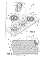
- FIG. 3 is an exploded isometric view of the device of FIG. 1 , with two of the covers exploded from the slide, and one cover shown in an assembled position.
- FIG. 4 is an enlarged cross-sectional view of the device of FIG. 1 , taken along section line 4-4.
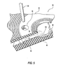
- FIG. 5 is a fragmentary perspective view, partially broken away in section, of an alternative embodiment specimen chamber of this invention, shown with a pipette in exploded view.
- FIG. 6 is an enlarged fragmentary plan view of the underside of the cover of FIG. 1 , showing a single rib.
- FIG. 7 is an enlarged fragmentary cross-sectional view of an alternative embodiment device of this invention, having a glue receiving recess on the underside of the cover perimeter.
- FIG. 8 is a cross-sectional view of an alternative embodiment device of this invention, in which the cover of FIG. 1 is adhered to a conventional glass slide.
- FIG. 9 is a cross-sectional view of an alternative embodiment device of this invention having a cover with an inverted channel positioned radially outwardly of the observation region.
- FIG. 10 is an enlarged view of the device of FIG. 9 , taken at section 10-10, to show the structure of a portion of a spacing rib.
- FIGS. 1B10 a device 20 which facilitates the analysis of specimens under magnification is shown in FIGS. 1B4 .
- the device 20 may serve as a cell counter or haemocytometer, or may be used for other analyses of cells or non-living elements, especially for extended duration or comparative analyses.
- the device 20 has three identical analysis units 22. It should be understood that a single device 20 may have only one analysis unit 22 or a greater number as required.
- the device 20 has a stiff transparent slide 24 which may be about one inch by three inches.
- the slide has recessed circular chambers 26 which each receive a generally circular transparent cover 28.
- the chambers may be about 18.7 mm in diameter, and spaced from one another on one-inch centers.
- the slide may be about 2.4 mm thick, while the cover may be about 0.6 mm thick.
- Both the covers 28 and the slide 24 may be formed of any suitably rigid transparent non-toxic material, for example Cyclic Olefin Copolymers (COC), which can be fabricated with optical grade clarity.
- COC Cyclic Olefin Copolymers
- the plastic used may also be polycarbonate. Note that there is preferably a parallel relationship between the unobscured viewing region 78 surface, the lower surface 32 of the cover 28, and the viewing platform annular surface 48.
- the slide 24 has an upper surface 30 within each chamber 26 which engages a lower surface 32 of the cover 28.
- the upper surface 30 of the chamber 26 is preferably recessed below a slide top surface 34, as shown in FIG. 2 .
- a side wall 38 extends between the upper surface 30 of the chamber 26 and the top surface 34 of the slide.
- Projections 40 extend radially inwardly from the side wall 38, and the projections are received within radially inwardly extending notches 36 formed in the covers 28.
- the cover 28 may be secured to the slide 24 by an adhesive resin 39 disposed in the notches 36, as the notches are larger than the projections 40 received therein.
- the cover is secured to the slide by the manufacturer, and thus the end user does not need to attach the cover, or handle adhesives. As shown FIG.
- the adhesive resin 39 is preferably a solvent based adhesive, but UV curable adhesives, or laser welding may also be used to attach the cover to the slide.
- a device 104 may be similar to the device 20, but may have a peripheral glue receiving recess 106 on the underside of the cover 108. The cover 108 is thus adhered directly to the slide 110.
- Each chamber 26 has a center well 42 which is recessed below the chamber upper surface 30.
- the chamber upper surface 30 is that portion of the slide which engages the lower surface 32 of the cover 28 and which is at a level higher than the level of a viewing platform 46.
- a ringlike overflow channel 44 encircles the center well 42, and is separated from the center well by the annular viewing platform 46 which encircles the center well.
- the overflow channel 44 is recessed, as best shown in FIG. 4 , below the viewing platform 46.
- the viewing platform 46 has an annular planar surface 48 which is spaced a constant distance below the chamber upper surface 30, and hence below the overlying cover 28 lower surface 32.
- the center well 42 is depressed below the level of the viewing platform surface 48.
- a viewing cavity 60 is thus defined between the viewing platform upper surface 48 and the lower surface 32 of the transparent cover 28. This cavity also serves as a capillary flow channel in fluid communication with the well 42 and the overflow channel 44.
- the distance between the viewing platform surface 48 and the chamber upper surface 30 is very small, generally about 5 to 50 microns, preferably about 12 microns or 20 microns, although devices with different spacing may be constructed to best accommodate a particular cell to be observed, 12 microns being adapted for boar semen, while 20 microns would be appropriate for rat semen.
- the thickness of the viewing cavity is thus defined between the underside of the cover and the planar surface 48 of the viewing platform 46.
- radially extending ribs 50 may be provided projecting downwardly from the lower surface 32 of the cover 28.
- the ribs 50 have the same thickness as the spacing of the viewing platform below the chamber upper surface 30.
- the ribs 50 abut against the viewing platform and maintain the desired spacing in viewing cavities 60 defined between the viewing platform surfaces 48 and the lower surface 32 of the cover and between the ribs 50.
- the viewing cavities are in fluid communication with both the center well 42 and the overflow channel 44.
- the ribs 50 may be formed as narrow closed rings of rib side wall 112.
- the rib side wall 112 thus defines a rib interior volume 114 beneath the cover lower surface 32, and a rib exterior volume 116 exterior to the rib.
- the cover 28 has a fluid sample inlet opening 62 which is a tapered opening, about 1/8th inch in diameter.
- the center well 42 is a smooth concave dish, as best shown in FIG. 2 .
- the center well may be about 6 mm in diameter.
- the fluid inlet opening 62 is centered over the central region 64 of the center well 42, which is the deepest portion of the center well.
- a continuous sloped lead-in ramp 66 extends between the central region 64 and the viewing platform surface 48. There are no ridges or discontinuities on the center well 42, and hence the free flow of fluid is not impeded.
- a fluid sample 68 containing cells 70, such as sperm, is introduced into the well through the inlet opening 62.
- a conventional pipette may be used to dispense the sample into the inlet opening.
- the sample which may be as large as about 20 ⁇ l is introduced slowly into the device 20.
- the center well 42 may have a volume of approximately 7 ⁇ l.
- the sample is dispensed into the center well from the pipette generally such that the fluid level extends above the level of the chamber upper surface 30.
- the fluid is drawn by capillary action between the cover and the viewing platform up the sloped lead-in ramp and into the viewing cavities 60.
- the depth of the center well 42 also provides a hydraulic force which drives the sample into the viewing cavities 60.
- a vent hole 72 extends through the cover 28 in a position directly over the overflow channel. As shown in FIG. 2 , the vent hole communicates with the overflow channel permitting the escape of air as fluid passes into the overflow channel from the viewing cavities 60.
- the vent hole 72 may be about 1mm in diameter.
- the fluid in the viewing cavities 60 is not restrained either on the side of the center well or on the side of the overflow channel. It is therefore possible to obtain an accurate count of cells in motion without having to take into consideration cells rebounding from a fixed boundary.
- the boundaries to the viewing cavities 60 presented by the ribs 50 are comparatively small, and care may be taken in the course of the observations to make a count in a region sufficiently spaced from a rib to minimize any impact on such a boundary.
- the device may be fabricated without ribs if desired. It should be noted that when used in analysis of sperm cells, the sperm cells will generally be in motion while under observation, and sperm cells can pass into the overflow channel from the viewing platform, and can pass from the overflow channel back on to the viewing platform.
- the upper surface 74 of the cover 28 is preferably provided with an obscuring surface treatment 76 on portions of the cover which surround a ring-like unobscured viewing region 78.
- the obscuring surface treatment 76 may be a series of concentric shallow ring-like depressions, as shown in FIG. 1 .
- An etched or frosted effect may also be employed for the obscuring surface treatment 76.
- the viewing platform surface 48, the surfaces of the cover, and the underside 80 of the slide be as clear and unobstructed as possible. These surfaces should be optical grade quality. Surfaces required to be optically clear may be fabricated by polishing the forming mold to the required degree. Typically, the covers and the slide will be formed in an injection molding process. Those parts of the device through which observations are taken should be formed in molds which have been accurately polished to avoid blemishes that would excessively detract from the optical properties of the device. The mold surfaces may be formed with diamond fly cutting and turning machines, such as is performed by the NetOptix division of Coming Incorporated, www.corningnetoptix.com. Although not necessary when used with automated counting systems, a grid may be formed in the cover or slide to facilitate counting cells within a defined region of a viewing cavity 60.
- a relieved region 82 may be formed beneath the viewing cavities 60.
- the relieved region keeps the underside 80 spaced from immediate contact with a tabletop, the microscope stage, etc., and helps to avoid scratching.
- the depth of the relief is sufficiently small that the heat from a heated microscope stage is not appreciably impeded in reaching the sample.
- the device 20 will be placed on an illuminated platform below a microscope objective. Alternatively, the device may be used with video based systems for sperm counting.
- the device 20 may be readily disposed of after use. By being disposable, not only is the expense of cleaning the device eliminated, but also the possibility of contaminating samples with material from previous uses.
- each rib 50 may be solid downward protrusions
- the construction of each rib as a closed ring of narrow rib side wall 112 permits the ribs to serve as a quality control measure in assembling the device 20. It will be observed that if the cover is properly attached by adhesive to the slide, the rib side walls 112 will engage against the slide so as to form a liquid tight seal. If due to some manufacturing error a liquid tight seal is not obtained, then, once liquid is introduced into the device, liquid may enter the rib interior volume 114 of a rib. This entrance of liquid into the rib interior volume will be detectable under magnification, and will signal to the user of the device that it is defective, allowing the user to discard the defective unit and continue observations with a new one.
- the ribs 50 may be formed as narrow closed rings of rib side wall 112.
- the rib side wall 112 thus defines a rib interior volume 114 beneath the cover lower surface 32, and a rib exterior volume 116 exterior to the rib.
- FIG. 5 An alternative embodiment device 84 which permits the ready addition of substances such as chemicals, active components, dyes, antibiotics or other additives, to a sample under observation is shown in FIG. 5 .
- the device 84 may be identical to the device 20, except that a secondary inlet port 86 is provided in the transparent cover 88 which overlies the slide 90.
- the inlet port 86 is a small diameter opening positioned in the unobscured viewing region 92 of the cover 88 to directly overlie the viewing platform 94 which is positioned between the central well 96 and the overflow channel 98.
- the inlet port 86 receives the tip of a pipette 100 to permit the introduction of substances to the sample 102 under observation.
- the device 84 thus allows a portion of the sample 102 to be observed prior to, during, and after the introduction of some substance which may alter the appearance of the sample.
- the device 84 is particularly helpful for determining the effect of particular additives on living specimens by observation while an additive infuses the culture medium.
- a medication or pharmaceutical product is tested for its effects on sperm motility.
- a boar semen specimen may be observed on the viewing platform 94 and the motility of the sperm cells assessed and recorded.
- Some additive substance may then be introduced into the sample on the viewing platform by injecting an additive through the inlet port. Then substantially the same sperm cells which had been previously observed can be analyzed immediately after their contact with the additive.
- Such a technique may also be particularly useful in analysis procedures which require dying or staining the sample in order to observe particular features of the sample.
- the device 84 permits the vigor and biological features of the sample to be carefully observed first, and then the special features only visible with the dye treatment to be observed. Any deleterious impact of the dye can thus be assessed and corrected for.
- the device can also be used for efficacy testing of antibiotics and other substances, where the reactions of the cells under observation can be viewed over time. For example, undesirable bacteria could be viewed in the viewing cavities, while a particular antibiotic or concentration of antibiotic is added through the secondary inlet port. The effect of the antibiotic on the growth of the bacteria could then be determined, without the need to remove the device from the microscope stage.
- the material may need to be treated in a conventional fashion to be made more hydrophilic.
- This treatment may include applying a oxygen plasma to the surface, or some type of corona treatment, or a gas plasma deposition of inert layers of metal, such as gold.
- a plastic cover of this invention may be used in connection with a glass slide, as in the devices 120, 126, shown in FIGS. 8 and 9 .
- the device 120 shown in FIG. 8 , affixes the cover 28 of the device 20 directly to a conventional glass slide 122.
- the ribs 50 serve to space the lower surface 32 of the cover 28 the desired uniform distance above the upper surface 124 of the glass slide 122.
- Adhesive resin 39 fixes the cover to the slide 122. However, the adhesive is positioned only within the notches 36, leaving the remainder of the perimeter of the cover open to the exterior.
- the sample 68 is then urged to flow beneath the viewing region 78, both by capillary action and by the hydraulic force of the sample within the inlet opening.
- the vent hole 72 which is in communication with the lower surface of the cover 28, permits excess quantities of sample to flow upwardly therein, and also prevents air captured beneath the cover from forming a bubble that would block the flow of sample. It is acceptable for a small portion of the sample to pass outwardly from under the cover around the periphery.
- the alternative embodiment device 126 also employs a conventional glass slide 122, but differs from the device 120 in having a plastic cover 128 with an upwardly extending overflow channel 130.
- the overflow channel 130 is a semi-annular relieved region which is positioned to encircle the sample inlet opening 132.
- the overflow channel 130 provides a volume which receives sample which is introduced through the inlet opening 132.
- the downwardly protruding ribs 134 shown in FIG. 10 , space the lower surface 136 of the cover 128 from the upper surface 124 of the glass slide 122.
- the cover 128 is affixed to the slide 122 by the adhesive resin 39 positioned within notches 138 at the periphery of the cover.
- the overflow channel 130 communicates with the upper surface 140 of the cover through a vent hole 142 which permits the escape of air bubbles.
- An unobscured viewing region 144 of the cover 128 is defined between the sample inlet opening 132 and the overflow channel 130. The spacing of the lower surface of the cover from the upper surface of the slide is maintained by the ribs 134 beneath the unobscured viewing region 144, and observations of the sample are taken in that region.
- cover 128 may be used in combination with the plastic slide 24 described above, such that the overflow channel 130 overlies the overflow channel 44, forming a combined channel above and below the upper level of the slide.
- the effects of the heated microscope stage can cause the sample to begin to dry out, with an undesirable impact on living organisms.
- the devices of this invention are particularly suited to extended observations, because, although the region being observed within the viewing cavities is very shallow, the center well 42, 96 and the overflow channel 44 are significantly deeper, and provide for a greater capacity of sample. Moreover, additional fluid in the form of more culture medium can be added to the sample through the sample inlet opening 62 during the course of observation to make up for any evaporation of liquid.
- the device of this invention may be used in genomics and proteomics for the observation of other elements such as DNA fragments, proteins, etc.
- genomics and proteomics for the observation of other elements such as DNA fragments, proteins, etc.
- the present invention provides an advantageously larger sample volume than in many prior art devices.
- the larger volume sample will tend to compensate for the dilution error which is produced when the original specimen is diluted to make a sample suitable for examination under a microscope.
- the diluted sample will not be entirely homogenous, and may thus exhibit variations in cell concentration throughout the specimen. To the extent that it is possible to take a larger portion of the sample, these variations of concentration may be overcome.
- the devices of this invention effectively provide a vessel without walls, and an accurately spaced thickness of fluid which permits a dynamic flow of the sperm from reservoirs on multiple sides of the viewing platform. Such an arrangement is conducive to sperm movement and longer survival.
Applications Claiming Priority (2)
| Application Number | Priority Date | Filing Date | Title |
|---|---|---|---|
| US11/142,929 US7718124B2 (en) | 2005-06-02 | 2005-06-02 | Counting, viability assessment, analysis and manipulation chamber |
| EP06771868A EP1886177B1 (fr) | 2005-06-02 | 2006-06-01 | Chambre de comptage, d'evaluation de viabilite, d'analyse et de manipulation |
Related Parent Applications (2)
| Application Number | Title | Priority Date | Filing Date |
|---|---|---|---|
| EP06771868.4 Division | 2006-06-01 | ||
| EP06771868A Division EP1886177B1 (fr) | 2005-06-02 | 2006-06-01 | Chambre de comptage, d'evaluation de viabilite, d'analyse et de manipulation |
Publications (2)
| Publication Number | Publication Date |
|---|---|
| EP2270573A1 true EP2270573A1 (fr) | 2011-01-05 |
| EP2270573B1 EP2270573B1 (fr) | 2014-08-13 |
Family
ID=36968495
Family Applications (2)
| Application Number | Title | Priority Date | Filing Date |
|---|---|---|---|
| EP06771868A Not-in-force EP1886177B1 (fr) | 2005-06-02 | 2006-06-01 | Chambre de comptage, d'evaluation de viabilite, d'analyse et de manipulation |
| EP10176272.2A Not-in-force EP2270573B1 (fr) | 2005-06-02 | 2006-06-01 | Couvercle de comptage, d'évaluation de viabilite, d'analyse et de manipulation |
Family Applications Before (1)
| Application Number | Title | Priority Date | Filing Date |
|---|---|---|---|
| EP06771868A Not-in-force EP1886177B1 (fr) | 2005-06-02 | 2006-06-01 | Chambre de comptage, d'evaluation de viabilite, d'analyse et de manipulation |
Country Status (6)
| Country | Link |
|---|---|
| US (1) | US7718124B2 (fr) |
| EP (2) | EP1886177B1 (fr) |
| AT (1) | ATE483179T1 (fr) |
| DE (1) | DE602006017206D1 (fr) |
| ES (1) | ES2504241T3 (fr) |
| WO (1) | WO2006130790A1 (fr) |
Families Citing this family (12)
| Publication number | Priority date | Publication date | Assignee | Title |
|---|---|---|---|---|
| US8852524B2 (en) * | 2010-01-12 | 2014-10-07 | Bio-Rad Laboratories, Inc. | Cell counting slide with lateral reservoir for promoting uniform cell distribution |
| CN202281862U (zh) * | 2011-08-31 | 2012-06-20 | 清华大学 | 体视显微镜 |
| WO2013127990A1 (fr) * | 2012-03-01 | 2013-09-06 | Victorious Medical Systems Aps | Procédé et système de répartition et d'agitation d'une quantité de liquide sur une lame de microscope |
| JP2013061357A (ja) * | 2013-01-08 | 2013-04-04 | Shimadzu Corp | 試料セル及びそれを用いた粒度分布測定装置 |
| US9663755B2 (en) | 2013-11-19 | 2017-05-30 | The Governing Council Of The University Of Toronto | Apparatus and methods for sperm separation |
| KR102179088B1 (ko) * | 2013-12-12 | 2020-11-18 | 메스 메디컬 일렉트로닉 시스템즈 리미티드 | 홈 테스팅 장치 |
| RU2021123492A (ru) * | 2016-04-22 | 2021-09-03 | Протеин Динамик Солюшнс, Инк. | Матричные устройства для образцов и система для спектрального анализа |
| CA3034619C (fr) * | 2016-08-26 | 2024-04-09 | Molecular Imprints, Inc. | Confinement de produit d'etancheite de bord et reduction de halo pour dispositifs optiques |
| US11513372B2 (en) | 2018-06-12 | 2022-11-29 | Magic Leap, Inc. | Edge sealant application for optical devices |
| JP7195419B2 (ja) | 2018-10-16 | 2022-12-23 | マジック リープ, インコーポレイテッド | ポリマー製品を鋳造するための方法および装置 |
| US20210053064A1 (en) * | 2019-08-20 | 2021-02-25 | Pattern Bioscience, Inc. | Microfluidic Chips Including a Gutter to Facilitate Loading Thereof and Related Methods |
| CN110567961A (zh) * | 2019-10-11 | 2019-12-13 | 长沙傲图生物科技有限公司 | 一种精液检测设备 |
Citations (4)
| Publication number | Priority date | Publication date | Assignee | Title |
|---|---|---|---|---|
| US4441793A (en) * | 1983-01-10 | 1984-04-10 | Elkins Carlos D | Microscopic evaluation slide |
| US4761381A (en) * | 1985-09-18 | 1988-08-02 | Miles Inc. | Volume metering capillary gap device for applying a liquid sample onto a reactive surface |
| US5229163A (en) * | 1989-12-21 | 1993-07-20 | Hoffmann-La Roche Inc. | Process for preparing a microtiter tray for immunometric determinations |
| US5948673A (en) * | 1995-09-12 | 1999-09-07 | Becton Dickinson And Company | Device and method for DNA amplification and assay |
Family Cites Families (20)
| Publication number | Priority date | Publication date | Assignee | Title |
|---|---|---|---|---|
| US1480391A (en) * | 1921-04-11 | 1924-01-08 | C A Hausser & Son | Haemacytometer |
| SE335630B (fr) * | 1964-08-31 | 1971-06-01 | H Unger | |
| US3829216A (en) * | 1968-11-26 | 1974-08-13 | M Persidsky | Optical system and method for counting sperm cells |
| US3705000A (en) * | 1971-06-01 | 1972-12-05 | American Optical Corp | Liquid sample holder for a photometer |
| US3961346A (en) * | 1975-01-30 | 1976-06-01 | Miles Laboratories, Inc. | Liquid inspection slide |
| JPS58179176A (ja) * | 1982-04-13 | 1983-10-20 | Mitsubishi Electric Corp | インバ−タ |
| US4790640A (en) * | 1985-10-11 | 1988-12-13 | Nason Frederic L | Laboratory slide |
| JPS6319532A (ja) | 1986-07-11 | 1988-01-27 | Sekisui Chem Co Ltd | 観察用プレ−ト |
| US4775515A (en) * | 1986-11-18 | 1988-10-04 | Cottingham Hugh V | Agglutinographic slide |
| US5503803A (en) * | 1988-03-28 | 1996-04-02 | Conception Technologies, Inc. | Miniaturized biological assembly |
| US5200152A (en) * | 1988-03-28 | 1993-04-06 | Cytonix Corporation | Miniaturized biological assembly |
| US4911782A (en) * | 1988-03-28 | 1990-03-27 | Cyto-Fluidics, Inc. | Method for forming a miniaturized biological assembly |
| US5349436A (en) * | 1992-12-02 | 1994-09-20 | Harry Fisch | Biological assembly |
| US5306467A (en) * | 1993-02-17 | 1994-04-26 | Hamilton-Thorn Research | Apparatus for measurement of cell concentration in a biological sample employing a magnetic slide loading apparatus |
| DE4403308C2 (de) | 1994-02-03 | 1997-04-17 | Madaus Ag | Objektträger für die Untersuchung von flüssigen Proben |
| DE4409786A1 (de) * | 1994-03-22 | 1995-09-28 | Boehringer Mannheim Gmbh | Objektträger zur mikroskopischen Auswertung flüssiger Proben |
| NL9500281A (nl) * | 1995-02-15 | 1996-09-02 | Jan Pieter Willem Vermeiden | Telkamer voor biologisch onderzoek alsmede werkwijze voor de vervaardiging van een dergelijke telkamer. |
| JPH09236756A (ja) | 1996-02-29 | 1997-09-09 | Fukae Kasei Kk | 光学顕微鏡用プラスチック・スライド |
| US6052224A (en) * | 1997-03-21 | 2000-04-18 | Northern Edge Associates | Microscope slide system and method of use |
| US6445451B1 (en) * | 1998-02-12 | 2002-09-03 | Hamilton Thorne Research | Colorimeter and assay device |
-
2005
- 2005-06-02 US US11/142,929 patent/US7718124B2/en active Active
-
2006
- 2006-06-01 EP EP06771868A patent/EP1886177B1/fr not_active Not-in-force
- 2006-06-01 DE DE602006017206T patent/DE602006017206D1/de active Active
- 2006-06-01 AT AT06771868T patent/ATE483179T1/de not_active IP Right Cessation
- 2006-06-01 EP EP10176272.2A patent/EP2270573B1/fr not_active Not-in-force
- 2006-06-01 WO PCT/US2006/021329 patent/WO2006130790A1/fr active Application Filing
- 2006-06-01 ES ES10176272.2T patent/ES2504241T3/es active Active
Patent Citations (4)
| Publication number | Priority date | Publication date | Assignee | Title |
|---|---|---|---|---|
| US4441793A (en) * | 1983-01-10 | 1984-04-10 | Elkins Carlos D | Microscopic evaluation slide |
| US4761381A (en) * | 1985-09-18 | 1988-08-02 | Miles Inc. | Volume metering capillary gap device for applying a liquid sample onto a reactive surface |
| US5229163A (en) * | 1989-12-21 | 1993-07-20 | Hoffmann-La Roche Inc. | Process for preparing a microtiter tray for immunometric determinations |
| US5948673A (en) * | 1995-09-12 | 1999-09-07 | Becton Dickinson And Company | Device and method for DNA amplification and assay |
Also Published As
| Publication number | Publication date |
|---|---|
| WO2006130790A1 (fr) | 2006-12-07 |
| EP1886177A1 (fr) | 2008-02-13 |
| US20060275743A1 (en) | 2006-12-07 |
| ATE483179T1 (de) | 2010-10-15 |
| ES2504241T3 (es) | 2014-10-08 |
| DE602006017206D1 (de) | 2010-11-11 |
| US7718124B2 (en) | 2010-05-18 |
| EP2270573B1 (fr) | 2014-08-13 |
| EP1886177B1 (fr) | 2010-09-29 |
| WO2006130790B1 (fr) | 2007-01-25 |
Similar Documents
| Publication | Publication Date | Title |
|---|---|---|
| EP1886177B1 (fr) | Chambre de comptage, d'evaluation de viabilite, d'analyse et de manipulation | |
| US10118177B2 (en) | Single column microplate system and carrier for analysis of biological samples | |
| US6720143B2 (en) | Genetic assay system | |
| KR101009447B1 (ko) | 체액 샘플링, 전처리 및 투입장치 및 방법 | |
| JP4755346B2 (ja) | 細胞培養の分析を実施する装置 | |
| JP4230816B2 (ja) | 試料の一部を自動的に貯蔵するプレート | |
| US4441793A (en) | Microscopic evaluation slide | |
| EP0496200A2 (fr) | Dispositif pour plusieurs échantillons | |
| US20130084632A1 (en) | Multi-reactor unit for dynamic cell culture | |
| US20240034968A1 (en) | Cell Culture Plate, Assembly And Methods Of Use | |
| TWI760783B (zh) | 生物檢測卡匣及其操作方法 | |
| CA2040920C (fr) | Appareil a capillaires et methode pour l'inoculation de sites multiples | |
| KR102127765B1 (ko) | 고형화된 유체의 이탈을 방지할 수 있는 신속한 세포배양검사 장치 | |
| JP2005509170A (ja) | 分析を行うための粒子を調整するための装置および方法 | |
| CN111629830A (zh) | 样品架 | |
| KR102132630B1 (ko) | 섬 구조물을 포함하는 신속한 세포배양검사 장치 | |
| KR102145842B1 (ko) | 정확한 관찰이 용이한 신속한 세포배양검사 장치 | |
| JP2004520593A (ja) | 微生物検査アレイ内の検査の統一性を維持する方法 | |
| US10606058B2 (en) | Microscope slide for liquid cultures | |
| KR102132635B1 (ko) | 유체막 두께가 일정한 신속한 세포배양검사 장치 | |
| US20230392104A1 (en) | Cell Culture Carrier | |
| WO2023086372A1 (fr) | Appareil de plaque de puits et son procédé de remplissage | |
| US20090232707A1 (en) | Apparatus for examining bodily fluids |
Legal Events
| Date | Code | Title | Description |
|---|---|---|---|
| PUAI | Public reference made under article 153(3) epc to a published international application that has entered the european phase |
Free format text: ORIGINAL CODE: 0009012 |
|
| AC | Divisional application: reference to earlier application |
Ref document number: 1886177 Country of ref document: EP Kind code of ref document: P |
|
| AK | Designated contracting states |
Kind code of ref document: A1 Designated state(s): AT BE BG CH CY CZ DE DK EE ES FI FR GB GR HU IE IS IT LI LT LU LV MC NL PL PT RO SE SI SK TR |
|
| RIN1 | Information on inventor provided before grant (corrected) |
Inventor name: SIMMET, LUDWIG O. |
|
| 17P | Request for examination filed |
Effective date: 20110705 |
|
| 17Q | First examination report despatched |
Effective date: 20120309 |
|
| GRAP | Despatch of communication of intention to grant a patent |
Free format text: ORIGINAL CODE: EPIDOSNIGR1 |
|
| GRAP | Despatch of communication of intention to grant a patent |
Free format text: ORIGINAL CODE: EPIDOSNIGR1 |
|
| INTG | Intention to grant announced |
Effective date: 20130807 |
|
| REG | Reference to a national code |
Ref country code: DE Ref legal event code: R079 Ref document number: 602006042733 Country of ref document: DE Free format text: PREVIOUS MAIN CLASS: G02B0021340000 Ipc: G01N0015140000 |
|
| RIC1 | Information provided on ipc code assigned before grant |
Ipc: G01N 15/14 20060101AFI20131218BHEP Ipc: G02B 21/34 20060101ALI20131218BHEP Ipc: B01L 3/00 20060101ALI20131218BHEP |
|
| GRAP | Despatch of communication of intention to grant a patent |
Free format text: ORIGINAL CODE: EPIDOSNIGR1 |
|
| INTG | Intention to grant announced |
Effective date: 20140207 |
|
| GRAS | Grant fee paid |
Free format text: ORIGINAL CODE: EPIDOSNIGR3 |
|
| GRAA | (expected) grant |
Free format text: ORIGINAL CODE: 0009210 |
|
| AC | Divisional application: reference to earlier application |
Ref document number: 1886177 Country of ref document: EP Kind code of ref document: P |
|
| AK | Designated contracting states |
Kind code of ref document: B1 Designated state(s): AT BE BG CH CY CZ DE DK EE ES FI FR GB GR HU IE IS IT LI LT LU LV MC NL PL PT RO SE SI SK TR |
|
| RAP1 | Party data changed (applicant data changed or rights of an application transferred) |
Owner name: MOFA GROUP LLC |
|
| REG | Reference to a national code |
Ref country code: GB Ref legal event code: FG4D |
|
| REG | Reference to a national code |
Ref country code: AT Ref legal event code: REF Ref document number: 682516 Country of ref document: AT Kind code of ref document: T Effective date: 20140815 Ref country code: CH Ref legal event code: EP |
|
| REG | Reference to a national code |
Ref country code: IE Ref legal event code: FG4D |
|
| REG | Reference to a national code |
Ref country code: DE Ref legal event code: R096 Ref document number: 602006042733 Country of ref document: DE Effective date: 20140925 |
|
| REG | Reference to a national code |
Ref country code: ES Ref legal event code: FG2A Ref document number: 2504241 Country of ref document: ES Kind code of ref document: T3 Effective date: 20141008 |
|
| REG | Reference to a national code |
Ref country code: NL Ref legal event code: T3 |
|
| REG | Reference to a national code |
Ref country code: AT Ref legal event code: MK05 Ref document number: 682516 Country of ref document: AT Kind code of ref document: T Effective date: 20140813 |
|
| REG | Reference to a national code |
Ref country code: LT Ref legal event code: MG4D |
|
| PG25 | Lapsed in a contracting state [announced via postgrant information from national office to epo] |
Ref country code: FI Free format text: LAPSE BECAUSE OF FAILURE TO SUBMIT A TRANSLATION OF THE DESCRIPTION OR TO PAY THE FEE WITHIN THE PRESCRIBED TIME-LIMIT Effective date: 20140813 Ref country code: PT Free format text: LAPSE BECAUSE OF FAILURE TO SUBMIT A TRANSLATION OF THE DESCRIPTION OR TO PAY THE FEE WITHIN THE PRESCRIBED TIME-LIMIT Effective date: 20141215 Ref country code: BG Free format text: LAPSE BECAUSE OF FAILURE TO SUBMIT A TRANSLATION OF THE DESCRIPTION OR TO PAY THE FEE WITHIN THE PRESCRIBED TIME-LIMIT Effective date: 20141113 Ref country code: SE Free format text: LAPSE BECAUSE OF FAILURE TO SUBMIT A TRANSLATION OF THE DESCRIPTION OR TO PAY THE FEE WITHIN THE PRESCRIBED TIME-LIMIT Effective date: 20140813 Ref country code: LT Free format text: LAPSE BECAUSE OF FAILURE TO SUBMIT A TRANSLATION OF THE DESCRIPTION OR TO PAY THE FEE WITHIN THE PRESCRIBED TIME-LIMIT Effective date: 20140813 Ref country code: GR Free format text: LAPSE BECAUSE OF FAILURE TO SUBMIT A TRANSLATION OF THE DESCRIPTION OR TO PAY THE FEE WITHIN THE PRESCRIBED TIME-LIMIT Effective date: 20141114 |
|
| PG25 | Lapsed in a contracting state [announced via postgrant information from national office to epo] |
Ref country code: CY Free format text: LAPSE BECAUSE OF FAILURE TO SUBMIT A TRANSLATION OF THE DESCRIPTION OR TO PAY THE FEE WITHIN THE PRESCRIBED TIME-LIMIT Effective date: 20140813 Ref country code: AT Free format text: LAPSE BECAUSE OF FAILURE TO SUBMIT A TRANSLATION OF THE DESCRIPTION OR TO PAY THE FEE WITHIN THE PRESCRIBED TIME-LIMIT Effective date: 20140813 Ref country code: IS Free format text: LAPSE BECAUSE OF FAILURE TO SUBMIT A TRANSLATION OF THE DESCRIPTION OR TO PAY THE FEE WITHIN THE PRESCRIBED TIME-LIMIT Effective date: 20141213 Ref country code: LV Free format text: LAPSE BECAUSE OF FAILURE TO SUBMIT A TRANSLATION OF THE DESCRIPTION OR TO PAY THE FEE WITHIN THE PRESCRIBED TIME-LIMIT Effective date: 20140813 |
|
| REG | Reference to a national code |
Ref country code: DE Ref legal event code: R082 Ref document number: 602006042733 Country of ref document: DE Representative=s name: PATENTANWALTSKANZLEI MEYER, DE |
|
| REG | Reference to a national code |
Ref country code: DE Ref legal event code: R082 Ref document number: 602006042733 Country of ref document: DE Representative=s name: PATENTANWALTSKANZLEI MEYER, DE Effective date: 20150302 Ref country code: DE Ref legal event code: R081 Ref document number: 602006042733 Country of ref document: DE Owner name: MOFA GROUP LLC, VERONA, US Free format text: FORMER OWNER: MOFA GROUP LLC, SHAWANO, WIS., US Effective date: 20150302 |
|
| PG25 | Lapsed in a contracting state [announced via postgrant information from national office to epo] |
Ref country code: CZ Free format text: LAPSE BECAUSE OF FAILURE TO SUBMIT A TRANSLATION OF THE DESCRIPTION OR TO PAY THE FEE WITHIN THE PRESCRIBED TIME-LIMIT Effective date: 20140813 Ref country code: SK Free format text: LAPSE BECAUSE OF FAILURE TO SUBMIT A TRANSLATION OF THE DESCRIPTION OR TO PAY THE FEE WITHIN THE PRESCRIBED TIME-LIMIT Effective date: 20140813 Ref country code: DK Free format text: LAPSE BECAUSE OF FAILURE TO SUBMIT A TRANSLATION OF THE DESCRIPTION OR TO PAY THE FEE WITHIN THE PRESCRIBED TIME-LIMIT Effective date: 20140813 Ref country code: EE Free format text: LAPSE BECAUSE OF FAILURE TO SUBMIT A TRANSLATION OF THE DESCRIPTION OR TO PAY THE FEE WITHIN THE PRESCRIBED TIME-LIMIT Effective date: 20140813 Ref country code: RO Free format text: LAPSE BECAUSE OF FAILURE TO SUBMIT A TRANSLATION OF THE DESCRIPTION OR TO PAY THE FEE WITHIN THE PRESCRIBED TIME-LIMIT Effective date: 20140813 |
|
| RAP2 | Party data changed (patent owner data changed or rights of a patent transferred) |
Owner name: MOFA GROUP LLC |
|
| REG | Reference to a national code |
Ref country code: DE Ref legal event code: R097 Ref document number: 602006042733 Country of ref document: DE |
|
| PG25 | Lapsed in a contracting state [announced via postgrant information from national office to epo] |
Ref country code: PL Free format text: LAPSE BECAUSE OF FAILURE TO SUBMIT A TRANSLATION OF THE DESCRIPTION OR TO PAY THE FEE WITHIN THE PRESCRIBED TIME-LIMIT Effective date: 20140813 |
|
| PLBE | No opposition filed within time limit |
Free format text: ORIGINAL CODE: 0009261 |
|
| STAA | Information on the status of an ep patent application or granted ep patent |
Free format text: STATUS: NO OPPOSITION FILED WITHIN TIME LIMIT |
|
| 26N | No opposition filed |
Effective date: 20150515 |
|
| PG25 | Lapsed in a contracting state [announced via postgrant information from national office to epo] |
Ref country code: SI Free format text: LAPSE BECAUSE OF FAILURE TO SUBMIT A TRANSLATION OF THE DESCRIPTION OR TO PAY THE FEE WITHIN THE PRESCRIBED TIME-LIMIT Effective date: 20140813 |
|
| PG25 | Lapsed in a contracting state [announced via postgrant information from national office to epo] |
Ref country code: MC Free format text: LAPSE BECAUSE OF FAILURE TO SUBMIT A TRANSLATION OF THE DESCRIPTION OR TO PAY THE FEE WITHIN THE PRESCRIBED TIME-LIMIT Effective date: 20140813 |
|
| REG | Reference to a national code |
Ref country code: CH Ref legal event code: PL |
|
| PG25 | Lapsed in a contracting state [announced via postgrant information from national office to epo] |
Ref country code: LU Free format text: LAPSE BECAUSE OF FAILURE TO SUBMIT A TRANSLATION OF THE DESCRIPTION OR TO PAY THE FEE WITHIN THE PRESCRIBED TIME-LIMIT Effective date: 20150601 |
|
| REG | Reference to a national code |
Ref country code: IE Ref legal event code: MM4A |
|
| PG25 | Lapsed in a contracting state [announced via postgrant information from national office to epo] |
Ref country code: CH Free format text: LAPSE BECAUSE OF NON-PAYMENT OF DUE FEES Effective date: 20150630 Ref country code: IE Free format text: LAPSE BECAUSE OF NON-PAYMENT OF DUE FEES Effective date: 20150601 Ref country code: LI Free format text: LAPSE BECAUSE OF NON-PAYMENT OF DUE FEES Effective date: 20150630 |
|
| REG | Reference to a national code |
Ref country code: FR Ref legal event code: PLFP Year of fee payment: 11 |
|
| PG25 | Lapsed in a contracting state [announced via postgrant information from national office to epo] |
Ref country code: BE Free format text: LAPSE BECAUSE OF FAILURE TO SUBMIT A TRANSLATION OF THE DESCRIPTION OR TO PAY THE FEE WITHIN THE PRESCRIBED TIME-LIMIT Effective date: 20140813 |
|
| PG25 | Lapsed in a contracting state [announced via postgrant information from national office to epo] |
Ref country code: HU Free format text: LAPSE BECAUSE OF FAILURE TO SUBMIT A TRANSLATION OF THE DESCRIPTION OR TO PAY THE FEE WITHIN THE PRESCRIBED TIME-LIMIT; INVALID AB INITIO Effective date: 20060601 |
|
| REG | Reference to a national code |
Ref country code: FR Ref legal event code: PLFP Year of fee payment: 12 |
|
| PG25 | Lapsed in a contracting state [announced via postgrant information from national office to epo] |
Ref country code: TR Free format text: LAPSE BECAUSE OF FAILURE TO SUBMIT A TRANSLATION OF THE DESCRIPTION OR TO PAY THE FEE WITHIN THE PRESCRIBED TIME-LIMIT Effective date: 20140813 |
|
| REG | Reference to a national code |
Ref country code: FR Ref legal event code: PLFP Year of fee payment: 13 |
|
| PGFP | Annual fee paid to national office [announced via postgrant information from national office to epo] |
Ref country code: NL Payment date: 20180626 Year of fee payment: 13 |
|
| PGFP | Annual fee paid to national office [announced via postgrant information from national office to epo] |
Ref country code: FR Payment date: 20180626 Year of fee payment: 13 |
|
| PGFP | Annual fee paid to national office [announced via postgrant information from national office to epo] |
Ref country code: GB Payment date: 20180627 Year of fee payment: 13 Ref country code: ES Payment date: 20180702 Year of fee payment: 13 Ref country code: IT Payment date: 20180621 Year of fee payment: 13 Ref country code: DE Payment date: 20180627 Year of fee payment: 13 |
|
| REG | Reference to a national code |
Ref country code: DE Ref legal event code: R082 Ref document number: 602006042733 Country of ref document: DE Representative=s name: BOEHMERT & BOEHMERT ANWALTSPARTNERSCHAFT MBB -, DE Ref country code: DE Ref legal event code: R082 Ref document number: 602006042733 Country of ref document: DE |
|
| REG | Reference to a national code |
Ref country code: GB Ref legal event code: 732E Free format text: REGISTERED BETWEEN 20190228 AND 20190306 |
|
| REG | Reference to a national code |
Ref country code: DE Ref legal event code: R081 Ref document number: 602006042733 Country of ref document: DE Owner name: MINITUEB GMBH, DE Free format text: FORMER OWNER: MOFA GROUP LLC, VERONA, WIS., US |
|
| REG | Reference to a national code |
Ref country code: ES Ref legal event code: PC2A Owner name: MINITUEB GMBH Effective date: 20190510 |
|
| REG | Reference to a national code |
Ref country code: NL Ref legal event code: PD Owner name: MINITUEB GMBH; DE Free format text: DETAILS ASSIGNMENT: CHANGE OF OWNER(S), ASSIGNMENT; FORMER OWNER NAME: MOFA GROUP LLC Effective date: 20190510 |
|
| REG | Reference to a national code |
Ref country code: DE Ref legal event code: R119 Ref document number: 602006042733 Country of ref document: DE |
|
| REG | Reference to a national code |
Ref country code: NL Ref legal event code: MM Effective date: 20190701 |
|
| GBPC | Gb: european patent ceased through non-payment of renewal fee |
Effective date: 20190601 |
|
| PG25 | Lapsed in a contracting state [announced via postgrant information from national office to epo] |
Ref country code: NL Free format text: LAPSE BECAUSE OF NON-PAYMENT OF DUE FEES Effective date: 20190701 Ref country code: GB Free format text: LAPSE BECAUSE OF NON-PAYMENT OF DUE FEES Effective date: 20190601 Ref country code: DE Free format text: LAPSE BECAUSE OF NON-PAYMENT OF DUE FEES Effective date: 20200101 Ref country code: IT Free format text: LAPSE BECAUSE OF NON-PAYMENT OF DUE FEES Effective date: 20190601 |
|
| PG25 | Lapsed in a contracting state [announced via postgrant information from national office to epo] |
Ref country code: FR Free format text: LAPSE BECAUSE OF NON-PAYMENT OF DUE FEES Effective date: 20190630 |
|
| REG | Reference to a national code |
Ref country code: ES Ref legal event code: FD2A Effective date: 20201027 |
|
| PG25 | Lapsed in a contracting state [announced via postgrant information from national office to epo] |
Ref country code: ES Free format text: LAPSE BECAUSE OF NON-PAYMENT OF DUE FEES Effective date: 20190602 |