EP2270572B1 - Microscope system and method for controlling it - Google Patents
Microscope system and method for controlling it Download PDFInfo
- Publication number
- EP2270572B1 EP2270572B1 EP10006549.9A EP10006549A EP2270572B1 EP 2270572 B1 EP2270572 B1 EP 2270572B1 EP 10006549 A EP10006549 A EP 10006549A EP 2270572 B1 EP2270572 B1 EP 2270572B1
- Authority
- EP
- European Patent Office
- Prior art keywords
- light
- voltage
- light control
- unit
- objective lens
- Prior art date
- Legal status (The legal status is an assumption and is not a legal conclusion. Google has not performed a legal analysis and makes no representation as to the accuracy of the status listed.)
- Active
Links
Images


Classifications
-
- G—PHYSICS
- G02—OPTICS
- G02B—OPTICAL ELEMENTS, SYSTEMS OR APPARATUS
- G02B21/00—Microscopes
- G02B21/06—Means for illuminating specimens
Definitions
- the present invention relates to light control of a microscope system.
- a conventional halogen lamp light source has been replaced with an LED (light emitting diode) illumination light source as illumination light of a microscope for the following reasons. That is, since a halogen lamp largely changes its color temperature (chromaticity) by light control, it is necessary to provide an optical element such as a darkening filter etc. for light control without changing the chromaticity. On the other hand, an LED can perform the light control only by changing a voltage and a current almost without changing the chromaticity. Therefore, when an LED is used as a light source, it has the merit of requiring no additional configuration. With predetermined quantity of light, an LED requires much less power consumption than a halogen lamp. Accordingly, when an LED is used as a light source, it has the merit of reducing excess power or heat.
- LED light emitting diode
- the emission efficiency of an LED has made rapid improvement, and has realized the luminance that can be used for a microscope.
- WO 2006/042624 A1 discloses a microscope system comprising an LED illumination lamp and implementing an intensity control based on a difference between a set value and a feedback value.
- the intensity control can represent the intensity control of a halogen illumination lamp based on a conversion function.
- EP 0 119 857 A1 discloses a microscope system comprising a halogen illumination lamp and a revolver supporting several objectives.
- a detecting means is capable of reading out the data of the objectives.
- Control means and light source adjusting means are also provided.
- JP 2004 085959 discloses a microscope system comprising a LED illumination lamp and a revolver for supporting the objectives.
- a control unit sets the luminance of the LED illumination lamp.
- US 2004/0217259 A1 discloses a microscope system with a zoom control.
- the microscope system according to the present invention is defined in claim 1.
- a method for controlling a microscope system is defined in claim 4.
- the quantity of light of an LED illumination system When the quantity of light of an LED illumination system is adjusted by turning the light control knob, the quantity of light increases by predetermined quantity by 10° turning the light control knob.
- the increase in quantity of light at this time is +1 [lx].
- the light control sensitivity of the LED indicates the characteristic (I ⁇ ⁇ ) that the quantity of light I( ⁇ ) linearly increases, the rate of increase in quantity of light to the turning degree of the light control knob is different between the low power observation and the high power observation.
- the light control sensitivity of a halogen lamp indicates a nonlinear change in the relationship between the turning degree ⁇ of the light control knob and the quantity of light I( ⁇ ). Therefore, between the low power observation and the high power observation, the rate of increase in quantity of light to the turning degree of the light control knob does not largely fluctuate as compared with the LED. Therefore, from the viewpoint of the operability, the light controlling operation of the LED illumination system is not easy for an observer who is familiar with the light control characteristic of the halogen lamp.
- the Japanese Patent No. 04071961 discloses substantially constant light control sensitivity in both low-power and high-power observations when the power of a zoom mechanism is changed.
- the Japanese Laid-open Patent Publication No. 2004-85959 discloses the technique of preventing insufficient or excessive quantity of light when an objective lens is switched.
- the Japanese Patent No. 04071961 does not refer to the light control sensitivity when an objective lens is switched.
- the Japanese Laid-open Patent Publication No. 2004-85959 can adjust the quantity of light around the set output voltage data, but does not refer to a further light controlling operation.
- the conventional technology lacks flexibility in the light controlling operation based on a sample and an observation environment.
- the embodiments according to the present invention provide a microscope system capable of easily performing an adjustment for the optimum light control sensitivity under any observation conditions.
- the microscope system includes an illumination unit, a light control direction unit, a storage unit, a light quantity control unit, and a control unit.
- the illumination unit illuminates a sample.
- the illumination unit is configured by, for example, a solid semiconductor element, and corresponds to a white LED 6 according to the present embodiment.
- the light control direction unit specifies the quantity of light output by the illumination unit.
- the light control direction unit corresponds to, for example, a light control knob 4 according to the present embodiment.
- the storage unit stores voltage-related information.
- the storage unit corresponds to, for example, ROM 1 according to the present embodiment.
- the voltage-related information direction values specified by the light control direction unit and voltage values to be applied to the illumination unit are associated with each other and are set.
- the direction values are in the entire range that can be specified by the light control direction unit.
- Each of The voltage value is corresponding to each of the direction value.
- the voltage-related information corresponds to, for example, a voltage table according to the present embodiment.
- the light quantity control unit controls the quantity of light emitted by the illumination unit.
- the light quantity control unit corresponds to, for example, a light quantity control device 3 according to the present embodiment.
- the control unit acquires a voltage value corresponding to the direction value specified by the light control direction unit from the voltage-related information, and allows the light quantity control unit to control the quantity of light based on the acquired voltage value.
- the control unit corresponds to, for example, a CPU 2 according to the present embodiment.
- the light control direction unit can turn a rotating scale, and can output the turning degree ⁇ of the scale as directive information.
- the voltage value set in each piece of voltage-related information is set so that the relationship between the turning degree ⁇ of the light control direction unit and the quantity of light of the illumination unit refers to I( ⁇ ) ⁇ ⁇ or I( ⁇ ) ⁇ EXP ( ⁇ ).
- the entire range of the light control knob can be used under any observation conditions. Accordingly, the light control can be finely performed.
- the microscope system above can further include an objective lens switch unit and an objective lens detection unit.
- the objective lens switch unit can support one or more objective lenses, and can switch the objective lenses arranged on the optical path for observation in the plurality of objective lenses.
- the objective lens switch unit corresponds to, for example, a revolver 8 according to the present embodiment.
- the objective lens detection unit detects an objective lens arranged on the optical path for observation in the plurality of objective lenses.
- the objective lens detection unit corresponds to, for example, a sensor 11 according to the present embodiment.
- the control unit selects the voltage-related information corresponding to the objective lens detected by the objective lens detection unit from among the pieces of voltage-related information, acquires a voltage value corresponding to the direction value specified by the light control direction unit from the selected voltage-related information, and allows the light quantity control unit to control the quantity of light based on the acquired voltage value.
- the entire range of the light control knob can be used after selecting any objective lens, thereby performing a fine adjustment of the light control.
- the microscope system can further include an observation method switch unit.
- the observation method switch unit can switch observation methods.
- the observation method switch unit corresponds to, for example, an observation method switch 7 according to the present embodiment.
- a voltage value depending on the observation method and corresponding to the direction value of the entire range that can be specified by the light control direction unit is set.
- the control unit selects the voltage-related information corresponding to the observation method switched by the observation method switch unit from among the pieces of voltage-related information, acquires the voltage value corresponding to the direction value specified by the light control direction unit from the selected voltage-related information, and allows the light quantity control unit to control the quantity of light based on the acquired voltage value.
- the entire range of the light control knob can be used after selecting any observation method, thereby performing a fine adjustment of the light control.
- the light quantity control unit can control the quantity of light of illumination light by changing the energizing pulse width to the illumination unit.
- the rate of change in quantity of light to the turning degree of the light control knob can be constant by having the relationship of I( ⁇ ) ⁇ EXP ( ⁇ ) between the turning degree ⁇ of the light control knob and the quantity of light I( ⁇ ).
- FIG. 1 illustrates the relationship between the turning degree of a normal light control knob and the quantity of light.
- the light control sensitivity is different between the low and high power observations because the light control characteristic of an LED refers to a linear increase of the quantity of light I( ⁇ ) to the turning degree ⁇ of the light control knob as indicated by the broken line in FIG. 1 .
- Ideal light control sensitivity refers to a constant rate of increase in quantity of light at any magnification.
- the light control sensitivity is expressed by the curve of the solid line in FIG. 1 , and the relationship between the turning degree ⁇ of the light control knob and the quantity of light I( ⁇ ) is expressed by I( ⁇ ) ⁇ EXP ( ⁇ ).
- I( ⁇ ) ⁇ EXP ( ⁇ ) In the illumination system of the conventional halogen lamp has the light control characteristic of I( ⁇ ) ⁇ EXP ( ⁇ ) substantially.
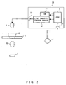
- FIG. 2 is an entire configuration (first configuration example) of the microscope system according to the first embodiment.
- FIG. 2 illustrates the configuration of the microscope system in an observation method in which transmission light from a sample is used.
- the microscope system is mainly configured by a microscope device body, an illumination control device 20, and the light control knob 4.
- the microscope device body has a stage 5, the white LED 6, an objective lens 15, and an eyepiece 9.
- the illumination control device 20 has the ROM (read only memory) 1, the CPU (central processing unit) 2, the light quantity control device 3, an input interface (hereinafter an interface is referred to as an I/F) 21, and an I/F 22 for a light source.
- ROM read only memory
- CPU central processing unit
- I/F input interface
- the input I/F 21 is connected to the light control knob 4 as a light control direction unit, and receives an operation direction signal from the light control knob 4.
- the white LED 6 is connected to the I/F 22 for a light source.
- the illumination control device 20 can also includes an interface for connection to the microscope body and other peripheral devices.
- the stage 5 is loaded with a sample 10, and an aperture is provided at the center of the stage.
- the objective lens 15 and the eyepiece 9 are positioned below the stage 5.
- the white LED 6 is used as an illumination light source.
- the light control knob 4 as a rotatable dial specifies the quantity of light of the white LED 6.
- the CPU 2 is connected to the input I/F 21, the I/F 22 for a light source, the ROM 1, and the light quantity control device 3.
- the CPU 2 can receive a direction signal from the light control knob 4 through the input I/F 21.
- the ROM 1 records a voltage table storing the voltage value associated with the turning degree ⁇ of the light control knob 4 as expressed by the relationship of I( ⁇ ) ⁇ EXP ( ⁇ ) between the quantity of light I ( ⁇ ) and the turning degree ⁇ of the light control knob 4.
- the light quantity control device 3 is configured by an A/D converter, a PWM (pulse width modulation) control device, etc.
- the light quantity control device 3 can supply a voltage to the white LED 6 by varying the energizing pulse width t.
- the energizing pulse width varies from the minimum pulse width to the maximum pulse width depending on the value 0 through 255 output from the A/D converter. When the pulse width is the maximum, continuous lightening is performed.
- the light quantity control device 3 can control the quantity of light of the white LED 6 through the I/F 22 for a light source.
- the information about the turning degree of the light control knob 4 is sequentially detected by the CPU 2.
- the CPU 2 reads a voltage value from the voltage table (for example at the storage address of 0011h) stored in the ROM 1.
- the CPU 2 sets the read voltage value in the light quantity control device 3.
- the light quantity control device 3 controls the quantity of light of the white LED 6 based on the set voltage value.
- the change of the quantity of light by the turning degree of the light control knob 4 can be freely changed by using the voltage table stored in the ROM 1.
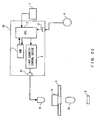
- FIG. 3 is an entire configuration (second configuration example) of the microscope system according to the first embodiment.
- a mirror 19 having the transmittance for transmission of the light of the white LED 6 and the reflectance for reflection of the light from the sample 10 is added to the configuration illustrated in FIG. 2 .
- the objective lens 15 and the eyepiece 9 is set above the sample 10.
- the present embodiment can be applied to the microscope system having the configurations illustrated in FIGS. 2 and 3 , but the configuration illustrated in FIG. 2 is described below for convenience in explanation.
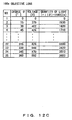
- FIG. 4 is an example of the voltage table according to the first embodiment.
- the voltage table in FIG. 4 stores a turning degree ⁇ and a voltage value corresponding to the turning degree ⁇ so that the relationship of I( ⁇ ) ⁇ EXP ( ⁇ ) can hold between the turning degree ⁇ of the light control knob 4 and the quantity of light I( ⁇ ).
- a voltage value is set for each turning degree of 15° of the light control knob 4.
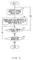
- FIG. 5 is the control flow of light control sensitivity according to the first embodiment.
- the light control method is described below with reference to FIG. 5 .
- the value of the turning degree ⁇ is detected by the CPU 2 (S1).
- the CPU 2 reads the voltage value corresponding to the turning degree ⁇ from the voltage table stored in the ROM 1, and outputs the value to the light quantity control device 3 (S2).
- the light quantity control device 3 provides the power based on the voltage value got the white LED 6.
- the microscope system in the second embodiment in which when the relationship of I( ⁇ ) ⁇ ⁇ holds between the turning degree ⁇ of the light control knob and the quantity of light I( ⁇ ), the light control can be finely adjusted by changing the range in which light control can be performed depending on the objective lens.
- FIG. 6 illustrates the range of light control of the light control knob used for each objective lens when the relationship of I( ⁇ ) ⁇ ⁇ between the turning degree ⁇ of the light control knob and the quantity of light I( ⁇ ), and a voltage table shared in all objective lenses is used.
- the quantity of light of each objective lens can be: (1) in the range of 0 through 30% with a 10 ⁇ objective lens; (2) in the range of 30 through 60% with a 4x objective lens; and (3) in the range of 60 through 100% with a 100 ⁇ objective lens. Therefore, the range of light control knob is limited depending on the objective lens to be used. Accordingly, there are the problems that it is difficult to finely adjust the light control, that a wasteful light controlling operation is performed in a range of unnecessary quantity of light, that the rate of increase in quantity of light is not constant, etc. Therefore, in the present embodiment, a voltage table is provided for each objective lens as illustrated in FIG. 7 , and the voltage table is set depending on each objective lens.
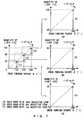
- FIG. 7 is a graph in which the range of light control is set for each objective lens in the second embodiment.
- the left graph in FIG. 7 is the same as the graph in FIG. 6 , and illustrates the range of light control of the light control knob used in each objective lens when a common voltage table is used for all objective lenses.
- the graph (A) in FIG. 7 illustrates the light control characteristic (1) when a voltage table in which the light control area (range of the quantity of light of 0 through 30%) available for the 10 ⁇ objective lens as illustrated in the left graph in FIG. 7 is extracted so that the turning degree of the light control knob 0 through 100° can be used in the range of the light control knob 0 through 360° is used.
- the graph (B) in FIG. 7 illustrates the light control characteristic (2) when a voltage table in which the light control area (range of the quantity of light of 30 through 60%) available for the 40 ⁇ objective lens as illustrated in the left graph in FIG. 7 is extracted so that the turning degree of the light control knob 100 through 200° can be used in the range of the light control knob 0 through 360° is used.
- the graph (C) in FIG. 7 illustrates the light control characteristic (3) when a voltage table in which the light control area (range of the quantity of light of 60 through 100%) available for the 100 ⁇ objective lens as illustrated in the left graph in FIG. 7 is extracted so that the turning degree of the light control knob 200 through 360° can be used in the range of the light control knob 0 through 360° is used.
- FIG. 8 is an entire configuration of the microscope system according to the second embodiment.
- the configuration illustrated in FIG. 8 is obtained by adding the revolver 8, the sensor 11, magnets 12, 13, and 14, the objective lenses 15, 16, and 17, and an input I/F 23 to the configuration illustrated in FIG. 2 . These members can be added to the configuration illustrated in FIG. 3 .
- One or more objective lenses 15 through 17 can be loaded into the revolver 8.
- the revolver 8 can be manually switched.
- the input I/F 23 is connected to the sensor 11, and receives a detection signal from the sensor 11.
- the magnets 12 through 14 are loaded respectively into the objective lenses 15 through 17. Based on the number of magnets loaded into the objective lenses, the sensor 11 arranged in the vicinity of the optical axis reacts.
- the ROM 1 records a voltage table for each objective lens depending on the objective lens.
- the objective lenses 15 through 17 three types of lenses, that is, the lenses of 10 ⁇ , 40 ⁇ , and 100 ⁇ , are used.
- the voltage tables corresponding to the respective objective lenses are, for example, sequentially assigned to the addresses 0021h, 0022h, and 0023h of the ROM 1.
- the CPU 2 is connected to the input I/F 21, the I/F 22 for a light source, the input I/F 23, the ROM 1, and the light quantity control device 3.
- the CPU 2 can receive a detection signal from the sensor 11 through the input I/F 23.
- the information about the turning degree of the light control knob 4 is sequentially detected by the CPU 2. Based on the detection result of the sensor 11, the CPU 2 reads the voltage table of the objective lens being used from the ROM 1. Then, the CPU 2 reads the voltage value from the voltage table depending on the turning degree of the light control knob 4, and outputs the value to the light quantity control device 3. Based on the voltage value, the light quantity control device 3 controls the quantity of light of the white LED 6.
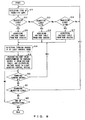
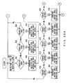
- FIG. 9 is a control flow of the range of light control depending on the magnification of an objective lens according to the second embodiment.
- the light control method is described below with reference to FIG. 9 .
- the number of each of the magnets 12 through 14 respectively loaded into the objective lenses 15 through 17 depends on the magnification of each objective lens.
- the sensor 11 detects the number of magnets loaded into the objective lens arranged on the optical axis (S11). The sensor 11 transmits the detection result as detected information to the CPU 2.
- the CPU 2 receives the detected information from the sensor 11, and identifies the objective lens arranged on the optical axis (S12 through S14). The CPU 2 reads the voltage table corresponding to the identified objective lens from the ROM 1 (S15 through S17). If no detected information is acquired from the sensor 11 in S12 through S14, control is returned to S11.
- the CPU 2 detects the value of the turning degree ⁇ of the light control knob 4 (S18), the CPU 2 reads the voltage value corresponding to the turning degree ⁇ from the voltage table acquired in any of S15 through S17, and outputs the voltage value to the light quantity control device 3 (S19).
- the light quantity control device 3 provides the white LED 6 with the power based on the voltage value.
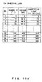
- FIGS. 10A , 10B , and 10C are examples of voltage tables when the objective lenses 15, 16, and 17 corresponding to the graphs (A), (B), and (C) in FIG. 7 are used.
- a voltage value is set for the voltage table corresponding to each objective lens stored in the ROM 1 so that the relationship of I( ⁇ ) ⁇ ⁇ can hold between the turning degree ⁇ of the 4 and the quantity of light 1(8).
- the lower limit of the quantity of light in FIG. 10B matches the upper limit in FIG. 10A .
- the lower limit of the quantity of light in FIG. 10C matches the upper limit in FIG. 10B .
- the light control can be finely adjusted depending on the objective lens.
- FIG. 11 is a graph in which the range of light control is set for each objective lens in the second embodiment (variation example 1). That is, FIG. 11 illustrates a variation of the example in FIG. 7 .
- the quantity of light at the turning degree ⁇ of the light control knob being 0° is 30% and 60% respectively.
- the quantity of light at the turning degree ⁇ of the light control knob being 0° is 30% and 60% respectively.
- the quantity of light is set as 0 when the turning degree ⁇ of the light control knob is 0° through the threshold, and the quantity of light increases depending on the turning degree ⁇ if the turning degree ⁇ exceeds the threshold.
- the relationship of I( ⁇ ) [proportional to] ⁇ holds.
- the light control knob when the turning degree ⁇ of the light control knob is 0° for 40x and 100x objective lenses, the quantity of light is 0[Ix], and when the turning degree ⁇ exceeds a predetermined threshold, the light control can be performed in a range of necessary quantity of light.
- the light can be completely turned off in graphs (B) and (C) of FIG. 11 , and consistent operability can be realized for all objective lenses and observation methods, thereby successfully improving the operability.
- it is useful from the viewpoint of energy-saving to enter the complete turned-off state.
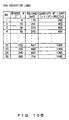
- FIGS. 12A , 12B , and 12C are examples of voltage tables when the objective lenses 15, 16, and 17 corresponding to the graphs (A), (B), and (C) in FIG. 11 are used.
- the lower limit of the quantity of light is 0.
- the light control can be performed in the range of necessary quantity of light for each objective lens.
- FIG. 13 illustrates the light control characteristic when there is the relationship of I ( ⁇ ) ⁇ ⁇ between the turning degree ⁇ of a light control knob 4 and the quantity of light I( ⁇ ) in the second embodiment (variation example 2), and the lower limit and the upper limit of the output voltage depending on each of the objective lenses 15 through 17 are stored in the voltage table.
- FIG. 11 when a 10 ⁇ objective lens is selected, no threshold is set for the turning degree ⁇ of the light control knob.
- FIG. 13 when a 10 ⁇ objective lens is service, the quantity of light is 0 for the turning degree ⁇ of the light control knob of 0° through the threshold, and when the turning degree ⁇ exceeds the threshold, the quantity of light increases depending on the turning degree ⁇ of the light control knob.
- the ranges of light control of the objective lenses do not overlap each other.
- the ranges of light control between the objective lenses partly overlap each other.
- the quantity of light is 40%, but if the turning degree ⁇ is nearly 0° when a 100 ⁇ objective lens is selected, the quantity of light is less than 40%.
- a lower limit and an upper limit can be set for the voltage value in the voltage table.
- a coefficient of I( ⁇ ) ⁇ ⁇ can be changed for each objective lens.
- any of the degrees from 0 to 360° can be used as the turning degree ⁇ of the light control knob 4 for each objective lens. Therefore, the light control can be finely adjusted depending on the objective lens.
- a lower limit and an upper limit can be set for the quantity of light that can be controlled depending on the objective lens.
- excess quantity of light unnecessary for an observation can be excluded, thereby quickly and easily performing the light controlling operation.
- various light control characteristics can be acquired by storing a voltage table in accordance with I( ⁇ ) ⁇ ⁇ for each objective lens in the ROM 1.
- Described in the third embodiment is the microscope system capable of finely adjusting the light control by changing the range of the light control depending on the objective lens when the relationship of I( ⁇ ) ⁇ EXP ( ⁇ ) holds between the turning degree ⁇ of the light control knob and the quantity of light I( ⁇ ).
- the present embodiment is different from the second embodiment in that the light control characteristic in accordance with I( ⁇ ) ⁇ ⁇ is replaced with the light control characteristic in accordance with I( ⁇ ) ⁇ EXP ( ⁇ ) for the voltage table.
- FIG. 14 illustrates the range of light control of the light control knob used for each objective lens when the relationship of I( ⁇ ) ⁇ EXP ( ⁇ ) between the turning degree ⁇ of the light control knob and the quantity of light I( ⁇ ), and a voltage table shared in all objective lenses is used.
- FIG. 15 is a graph in which the range of light control is set for each objective lens in the third embodiment.
- the graph on the left in FIG. 15 is the same as the graph in FIG. 14 , and illustrates the range of light control of the light control knob used in each objective lens when a voltage table shared by all objective lenses is used.
- the graph (A) in FIG. 15 illustrates the light control characteristic (1) when a voltage table in which the light control area (range of the quantity of light of 0 through 30%) available for the 10 ⁇ objective lens as illustrated in the left graph in FIG. 7 is extracted so that the turning degree of the light control knob can be used in the range of the light control knob 0 through 360° is used.
- the graph (B) in FIG. 15 illustrates the light control characteristic (2) when a voltage table in which the light control area (range of the quantity of light of 30 through 60%) available for the 40 ⁇ objective lens as illustrated in the left graph in FIG. 7 is extracted so that the turning degree of the light control knob can be used in the range of the light control knob 0 through 360° is used.
- the graph (C) in FIG. 15 illustrates the light control characteristic (3) when a voltage table in which the light control area (range of the quantity of light of 60 through 100%) available for the 100 ⁇ objective lens as illustrated in the left graph in FIG. 7 is extracted so that the turning degree of the light control knob can be used in the range of the light control knob 0 through 360° is used.
- the entire configuration of the microscope system according to the third embodiment is the same as the configuration illustrated in FIG. 8 .
- the control flow of the range of light control depending on the magnification of the objective lens according to the third embodiment is the same as the flow illustrated in FIG. 9 .
- the difference from the second embodiment is only the contents of the voltage table acquired in S15 through S17.
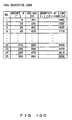
- FIGS. 16A , 16B , and 16C are examples of voltage tables when the objective lenses 15, 16, and 17 corresponding to the graphs (A), (B), and (C) in FIG. 15 are used.
- a voltage value is set for the voltage table corresponding to each objective lens stored in the ROM 1 so that the relationship of I( ⁇ [proportional to] EXP( ⁇ ) can hold between the turning degree ⁇ of the 4 and the quantity of light I( ⁇ ).
- the lower limit of the quantity of light in FIG. 16B matches the upper limit in FIG. 16A .
- the lower limit of the quantity of light in FIG. 16C matches the upper limit in FIG. 16B .
- the light control can be finely adjusted depending on the objective lens.
- FIG. 17 is a graph in which the range of light control is set for each objective lens in the third embodiment (variation example 1). That is, FIG. 17 illustrates a variation of the example in FIG. 15 .
- the quantity of light at the turning degree ⁇ of the light control knob being 0° is 30% and 60% respectively.
- the quantity of light at the turning degree ⁇ of the light control knob being 0° is 30% and 60% respectively.
- the quantity of light is set as 0 when the turning degree ⁇ of the light control knob is 0° through the threshold, and the quantity of light increases depending on the turning degree ⁇ if the turning degree ⁇ exceeds the threshold.
- the relationship of I( ⁇ ) ⁇ EXP( ⁇ ) holds.
- the light control knob when the turning degree ⁇ of the light control knob is 0° for 40x and 100x objective lenses, the quantity of light is 0 [Ix], and when the turning degree ⁇ exceeds a predetermined threshold, the light control can be performed in a range of necessary quantity of light.
- the light can be completely turned off in graphs (B) and (C) in FIG. 17 , and consistent operability can be realized for all objective lenses and observation methods, thereby successfully improving the operability.
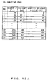
- FIGS. 18A , 18B , and 18C are examples of voltage tables when the objective lenses 15, 16, and 17 corresponding to the graphs (A), (B), and (C) in FIG. 17 are used.
- the lower limit of the quantity of light is 0.
- the light control can be performed in the range of necessary quantity of light for each objective lens.
- FIG. 19 illustrates the light control characteristic when there is the relationship of I ( ⁇ ) ⁇ EXP ( ⁇ ) between the turning degree ⁇ of a light control knob 4 and the quantity of light I( ⁇ ) in the third embodiment (variation example 2), and the lower limit and the upper limit of the output voltage depending on each of the objective lenses 15 through 17 are stored in the voltage table.
- the ranges of light control of the objective lenses do not overlap each other.
- the ranges of light control between the objective lenses partly overlap each other.
- the quantity of light is 50% or more, but if the turning degree ⁇ is nearly 0° when a 100 ⁇ objective lens is selected, the quantity of light is less than 50%.
- a coefficient of I ( ⁇ ) ⁇ EXP ( ⁇ ) can be changed for each objective lens.
- a lower limit and au upper limit can be set for the voltage value set in the voltage table.
- the rate of change in quantity of light to the turning degree ⁇ of the light control knob can be constant by setting the voltage table so that the relationship of I( ⁇ ) ⁇ EXP ( ⁇ ) can hold between the turning degree ⁇ of the light control knob 4 and the quantity of light I( ⁇ ). Therefore, the light control can be finely adjusted depending on the objective lens.
- any of the degrees from 0 to 360° can be used as the turning degree ⁇ of the light control knob 4 for each objective lens. Therefore, the light control can be finely adjusted depending on the objective lens.
- a lower limit and an upper limit can be set for the quantity of light that can be controlled depending on the objective lens.
- excess quantity of light unnecessary for an observation can be excluded, thereby quickly and easily performing the light controlling operation.
- Various light control characteristics can be acquired by storing a voltage table in accordance with I( ⁇ ) ⁇ EXP ( ⁇ ) in the ROM 1.
- predetermined light control sensitivity can be acquired.
- the microscope system in the fourth embodiment in which when the relationship of I( ⁇ ) ⁇ ⁇ holds between the turning degree ⁇ of the light control knob and the quantity of light I( ⁇ ), the light control can be finely adjusted by changing the range in which light control can be performed depending on the observation method.
- FIG. 20 is an entire configuration of the microscope system according to the fourth embodiment.
- the configuration illustrated in FIG. 20 is obtained by adding observation method switch 7 to the configuration illustrated in FIG. 2 .
- the member can be added to the configuration illustrated in FIG. 3 .
- the observation method can be switched using the observation method switch 7.
- the observation method switch 7 can switch three types of observations, that is, a bright sight observation, a phase difference observation, and a dark sight observation. Each observation method requires different quantity of light.
- the range of the quantity of light to be used depends on the observation method. Therefore, a voltage table depending on each observation method is required.
- the ROM 1 records each observation method. There are three types of observation methods, that is, the bright sight observation, the phase difference observation, and the dark sight observation.
- the voltage table for each of the observation methods is sequentially assigned to, for example, the addresses 0031h, 0032h, and 0033h of the ROM 1.
- the CPU 2 reads the voltage table depending on the observation method from the ROM 1, reads the voltage value from the read voltage table, and outputs the value to the light quantity control device 3.
- the light quantity control device 3 outputs power based on the voltage value to the white LED 6, and controls the quantity of light of the white LED 6.
- FIG. 21 is a control flow of the range of light control depending on the observation method in the fourth embodiment.
- the light control method is described below with reference to FIG. 21 .
- the user switches the observation methods (bright sight observation, phase difference observation, and dark sight observation) using the observation method switch 7. Then, the change information about any of the bright sight observation, the phase difference observation, and the dark sight observation that has been switched is transmitted from the observation method switch 7 to the CPU 2.
- the CPU 2 receives the change information from the observation method switch 7, and detects the state of the observation method switch 7 according to the change information (S31). According to the change information, the CPU 2 determines which has been switched to, the bright sight observation, the phase difference observation, or the dark sight observation (S32 through S34).
- the CPU 2 reads the voltage table corresponding to the determined observation method from any of the addresses 0031h, 0032h, and 0033h of the ROM 1 (S35 through S37). If the determination cannot be performed on the observation method in S32 through S34, control is returned to S31.
- the CPU 2 When the value of the turning degree ⁇ of the light control knob 4 is detected by the CPU 2 (S38), the CPU 2 reads the voltage value corresponding to the turning degree ⁇ from the voltage table of the ROM 1, and outputs the voltage value to the light quantity control device 3 (S39).
- the light quantity control device 3 provides the white LED 6 with the power based on the voltage value.
- the voltage value set in the voltage table depending on each observation method can also be set so that the relationship of I( ⁇ ) ⁇ ⁇ can hold between the turning degree ⁇ of the light control knob 4 and the quantity of light I ( ⁇ ) as in graphs (A), (B), and (C) of FIG. 7 .
- a lower limit and an upper limit can be set for the range of light control of each observation method.
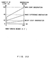
- FIG. 22 illustrates the light control characteristic when there is the relationship of I ( ⁇ ) ⁇ ⁇ between the turning degree ⁇ of a light control knob 4 and the quantity of light I( ⁇ ) in the fourth embodiment (variation example), and the lower limit and the upper limit of the output voltage depending on the observation method are stored in the voltage table.
- the light control can be finely adjusted depending on the observation method. Furthermore, excess quantity of light unnecessary for an observation can be excluded, thereby quickly and easily performing the light controlling operation.
- any of the degrees from 0 to 360° can be used as the turning degree ⁇ of the light control knob 4 depending on each observation method. Therefore, the light control can be finely adjusted depending on the observation method.
- a lower limit and an upper limit can be set for the quantity of light that can be controlled depending on the observation method.
- excess quantity of light unnecessary for an observation can be excluded, thereby quickly and easily performing the light controlling operation.
- Various light control characteristics can be acquired by storing a voltage table in accordance with I( ⁇ ) ⁇ ⁇ in the ROM 1.
- Described in the fifth embodiment is the microscope system capable of finely adjusting the light control by changing the range of the light control depending on the observation method when the relationship of I( ⁇ ) ⁇ EXP ( ⁇ ) holds between the turning degree ⁇ of the light control knob and the quantity of light I( ⁇ ).
- the present embodiment is a variation example of the fourth embodiment, and obtained by storing the voltage table in accordance with I( ⁇ ) ⁇ EXP ( ⁇ ) in the ROM 1 of the fourth embodiment.
- the same configurations as in the first through fourth embodiments are assigned the same reference numerals, and the description is omitted here.
- FIG. 23 illustrates the light control characteristic when there is the relationship of I( ⁇ ) ⁇ EXP ( ⁇ ) between the turning degree ⁇ of a light control knob 4 and the quantity of light I( ⁇ ) in the fifth embodiment, and the lower limit and the upper limit of the output voltage depending on the observation method are stored in the voltage table.
- the rate of change in quantity of light to the turning degree of the light control knob is constant, and the light control can be finely adjusted depending on the observation method.
- a lower limit and an upper limit can be set for the quantity of light that can be controlled depending on the objective lens.
- excess quantity of light unnecessary for an observation can be excluded, thereby quickly and easily performing the light controlling operation.
- various light control characteristics can be acquired by storing a voltage table in accordance with I( ⁇ ) ⁇ ⁇ EXP ( ⁇ ) in the ROM 1.
- constant light control sensitivity can be acquired by setting I( ⁇ ) ⁇ EXP ( ⁇ ).
- the present embodiment is a combination of the second and fourth embodiments.
- the same configurations as in the first through fourth embodiments are assigned the same reference numerals, and the descriptions are omitted here.
- FIG. 24 is an entire configuration of the microscope system according to the sixth embodiment.
- the configuration illustrated in FIG. 24 is obtained by adding the observation method switch 7, the revolver 8, the sensor 11, magnets 12, 13, and 14, and the objective lenses 15, 16, and 17 to the configuration illustrated in FIG. 2 .
- a voltage table corresponding to each combination of the objective lens and the observation method is stored in the ROM 1. Furthermore, the ROM 1 stores objective lens information, observation method information, etc.
- the CPU 2 reads the objective lens information and the observation method information from the ROM 1, and reads the voltage table corresponding to the combination from the ROM 1.
- three types of objective lenses for example, 10 ⁇ , 40 ⁇ , and 100 ⁇ objective lenses, are used as the objective lenses 15 through 17.
- the information about each objective lens is assigned to the addresses 0021h, 0022h, and 0023h of the ROM 1 respectively for the 10 ⁇ , 40 ⁇ , and 100 ⁇ objective lenses.
- each observation method is assigned to the addresses 0031h, 0032h, and 0033h of the ROM 1 respectively for the bright sight observation, the phase difference observation, and the dark sight observation.
- a voltage table corresponding to the combination of the objective lens and the observation method is prepared. For example, if there are three types of objective lenses, that is, the 10 ⁇ , 40 ⁇ , and 100 ⁇ objective lenses, and three types of observation methods, that is, bright sight observation, the phase difference observation, and the dark sight observation, then there are nine combinations of the objective lenses and the observation methods, and nine voltage tables are required.
- the ROM 1 stores the voltage tables different from one another depending on the combinations of the objective lenses and the observation methods.
- the CPU 2 reads the voltage table from the ROM 1 depending on the combination of the objective lens and the observation method, reads the voltage value from the voltage table depending on the turning degree of the light control knob 4, and outputs the voltage value to the light quantity control device 3.
- the light quantity control device 3 provides the white LED 6 with the power based on the voltage value.
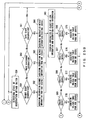
- FIGS. 25A , 25B and 25C are control flows of the range of light control depending on the objective lens and the observation method in the sixth embodiment.
- the light control method is described below with reference to FIGS. 25A , 25B and 25C .
- the number of the magnets 12 through 14 loaded into the objective lenses 15 through 17 depends on the magnification of the objective lens
- the sensor 11 detects the number of magnets loaded into the objective lens arranged on the optical axis (S51).
- the sensor 11 transmits the detection result as detected information to the CPU 2.
- the CPU 2 receives the detected information from the sensor 11, and identifies the objective lens arranged on the optical axis (S52 through S54).
- the CPU 2 reads the voltage table corresponding to the identified objective lens from the ROM 1 (S55 through S57). If the detected information from the sensor 11 cannot be acquired in S52 through S54, control is returned to S51.
- the user switches the observation method (bright sight observation, phase difference observation, dark sight observation) using the observation method switch 7. Then, the change information that any of the bright sight observation, the phase difference observation, and the dark sight observation has been switched is transmitted from the observation method switch 7 to the CPU 2.
- the CPU 2 receives the change information from the observation method switch 7 and detects the state of the observation method switch 7 according to the change information (S58). According to the change information, the CPU 2 determines which has been switched to, the bright sight observation, the phase difference observation, or the dark sight observation (S59 through S61).
- the CPU 2 reads the observation method information corresponding to the determined observation method from any of the addresses 0031h, 0032h, and 0033h of the ROM 1 (S62 through S64). If the observation method cannot be determined in S59 through S61, control is returned to S58.
- the CPU 2 checks the combination of the objective lens and the observation method (S65), and determines the combination (S66 through S74).
- the CPU 2 reads the voltage table corresponding to the determined combination of the objective lens and the observation method from any of the addresses 0041h through 0049h of the ROM 1 (S75 through S83).
- the CPU 2 detects the value of the turning degree ⁇ of the light control knob 4 (S84), the CPU 2 reads the voltage value corresponding to the turning degree ⁇ from the voltage table of the ROM 1, and outputs the voltage value to the light quantity control device 3 (S85).
- the light quantity control device 3 provides the white LED 6 with the power according to the voltage value.
- the voltage table stored in the ROM 1 when there is the following relationship between the turning degree ⁇ of the light control knob 4 and the quantity of light I( ⁇ ) is illustrated in FIG. 26 .
- FIG. 26 illustrates the light control characteristic when there is the relationship of I( ⁇ ) ⁇ ⁇ between the turning degree ⁇ of a light control knob 4 and the quantity of light I( ⁇ ) in the sixth embodiment, and the lower limit and the upper limit of the output voltage depending on the objective lens and the observation method are stored in the voltage table. With the configuration, the light control can be finely adjusted depending on the objective lens and the observation method.
- the light control performance can be furthermore improved than in the second or fourth embodiment depending on the combination of an objective lens and an observation method.
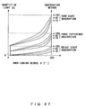
- the microscope system in the seventh embodiment in which when the relationship of I ( ⁇ ) ⁇ EXP ( ⁇ ) holds between the turning degree ⁇ of the light control knob and the quantity of light I( ⁇ ), the light control can be finely adjusted by changing the range in which light control can be performed depending on the objective lens and the observation method.
- the present embodiment is a combination of the third and fifth embodiments, and a variation example of the sixth embodiment.
- the ROM 1 stores the voltage table in accordance with I ( ⁇ ) ⁇ EXP ( ⁇ ).
- the same configurations as the first through fourth embodiments are assigned the same reference numerals, and the descriptions are omitted here.
- FIG. 27 illustrates the light control characteristic when there is the relationship of I( ⁇ ) ⁇ EXP ( ⁇ ) between the turning degree ⁇ of a light control knob 4 and the quantity of light I( ⁇ ) in the seventh embodiment, and the lower limit and the upper limit of the output voltage depending on the objective lens and the observation method are stored in the voltage table.
- the rate of change in quantity of light to the turning degree of the light control knob is constant and the light control can be finely adjusted depending on the objective lens and the observation method.
- the light control performance can be furthermore improved than in the third or fifth embodiment depending on the combination of an objective lens and an observation method.
- the entire range of the light control knob can be used although any objective lens, observation method, or combination of them is selected, thereby finely adjusting the light control.
- This can be realized by setting the turning degree ⁇ of the light control knob 4 in the voltage table and the voltage value corresponding to the turning degree ⁇ so that the relationship of I( ⁇ ) ⁇ ⁇ or I( ⁇ ) ⁇ EXP ( ⁇ ) can hold between the turning degree ⁇ of the light control knob 4 and the quantity of light I( ⁇ ).
- a voltage table is required depending on the objective lens or the observation method, but the present invention is not limited to this application, but the voltage table can be prepared depending on the component of switching other observation conditions.
- the lower limit and the upper limit of the quantity of light that can be controlled depending on the objective lens can be set.
- excess quantity of light unnecessary for an observation can be excluded, thereby quickly and easily performing the light controlling operation.
- an adjustment can be easily made for the optimum light control sensitivity under any observation condition in a microscope observation.
Landscapes
- Physics & Mathematics (AREA)
- Chemical & Material Sciences (AREA)
- Analytical Chemistry (AREA)
- General Physics & Mathematics (AREA)
- Optics & Photonics (AREA)
- Microscoopes, Condenser (AREA)
- Circuit Arrangement For Electric Light Sources In General (AREA)
Applications Claiming Priority (1)
| Application Number | Priority Date | Filing Date | Title |
|---|---|---|---|
| JP2009158157A JP5253309B2 (ja) | 2009-07-02 | 2009-07-02 | 顕微鏡システム、及び該制御方法 |
Publications (3)
| Publication Number | Publication Date |
|---|---|
| EP2270572A2 EP2270572A2 (en) | 2011-01-05 |
| EP2270572A3 EP2270572A3 (en) | 2011-02-23 |
| EP2270572B1 true EP2270572B1 (en) | 2014-04-09 |
Family
ID=42782195
Family Applications (1)
| Application Number | Title | Priority Date | Filing Date |
|---|---|---|---|
| EP10006549.9A Active EP2270572B1 (en) | 2009-07-02 | 2010-06-23 | Microscope system and method for controlling it |
Country Status (3)
| Country | Link |
|---|---|
| US (1) | US8451534B2 (https=) |
| EP (1) | EP2270572B1 (https=) |
| JP (1) | JP5253309B2 (https=) |
Families Citing this family (10)
| Publication number | Priority date | Publication date | Assignee | Title |
|---|---|---|---|---|
| JP5866882B2 (ja) * | 2011-08-31 | 2016-02-24 | 株式会社ニコン | 顕微鏡システムおよび制御プログラム |
| JP5803440B2 (ja) * | 2011-08-31 | 2015-11-04 | 株式会社ニコン | 調光装置、顕微鏡 |
| JP6688189B2 (ja) * | 2016-08-09 | 2020-04-28 | オリンパス株式会社 | 顕微鏡装置 |
| JP6818616B2 (ja) * | 2017-03-31 | 2021-01-20 | オリンパス株式会社 | 顕微鏡装置 |
| JP6417004B2 (ja) * | 2017-08-28 | 2018-10-31 | 株式会社トプコン | スリットランプ顕微鏡 |
| US11504927B2 (en) | 2018-03-23 | 2022-11-22 | TurnCare, Inc. | Systems and methods for controlling and monitoring inflatable perfusion enhancement apparatus for mitigating contact pressure |
| US11980565B2 (en) | 2018-03-23 | 2024-05-14 | TurnCare, Inc. | Inflatable perfusion enhancement apparatuses and associated devices, systems and methods |
| JP2020003659A (ja) * | 2018-06-28 | 2020-01-09 | オリンパス株式会社 | 拡大観察装置 |
| CN113556993B (zh) * | 2018-09-26 | 2024-04-26 | 旋转护理公司 | 控制和监测用于减缓接触压力的可膨胀灌注增强装置的系统和方法 |
| WO2021020477A1 (ja) * | 2019-07-31 | 2021-02-04 | 京セラ株式会社 | 照明システム |
Family Cites Families (12)
| Publication number | Priority date | Publication date | Assignee | Title |
|---|---|---|---|---|
| JPS59172617A (ja) * | 1983-03-22 | 1984-09-29 | Olympus Optical Co Ltd | 自動制御式照明光学系を備えた顕微鏡 |
| US5517353A (en) * | 1993-05-28 | 1996-05-14 | Nikon Corporation | Illuminating apparatus for a microscope |
| JP3406987B2 (ja) * | 1995-01-30 | 2003-05-19 | 株式会社ニコン | 電動式顕微鏡 |
| JP3537205B2 (ja) * | 1995-02-02 | 2004-06-14 | オリンパス株式会社 | 顕微鏡装置 |
| CN1295540C (zh) * | 2001-12-17 | 2007-01-17 | 奥林巴斯株式会社 | 显微镜系统 |
| JP4071961B2 (ja) * | 2001-12-17 | 2008-04-02 | オリンパス株式会社 | 顕微鏡システム |
| JP2004085959A (ja) * | 2002-08-28 | 2004-03-18 | Nikon Corp | 顕微鏡 |
| JP2005250151A (ja) * | 2004-03-04 | 2005-09-15 | Olympus Corp | 顕微鏡装置、その調光方法、及びその調光プログラム |
| DE102004051548A1 (de) * | 2004-10-20 | 2006-05-04 | Carl Zeiss Jena Gmbh | Beleuchtungseinrichtung für Mikroskope |
| US7433026B2 (en) * | 2005-12-20 | 2008-10-07 | Cytyc Corporation | Microscope with LED illumination source |
| WO2008124718A2 (en) * | 2007-04-10 | 2008-10-16 | Lumination Llc | Light emitting diode controller, methods of light emitting diode control, and components for same |
| JP2009025394A (ja) * | 2007-07-17 | 2009-02-05 | Olympus Corp | 顕微鏡システム |
-
2009
- 2009-07-02 JP JP2009158157A patent/JP5253309B2/ja active Active
-
2010
- 2010-06-23 EP EP10006549.9A patent/EP2270572B1/en active Active
- 2010-06-23 US US12/821,430 patent/US8451534B2/en active Active
Also Published As
| Publication number | Publication date |
|---|---|
| EP2270572A2 (en) | 2011-01-05 |
| JP5253309B2 (ja) | 2013-07-31 |
| US8451534B2 (en) | 2013-05-28 |
| EP2270572A3 (en) | 2011-02-23 |
| US20110002033A1 (en) | 2011-01-06 |
| JP2011013503A (ja) | 2011-01-20 |
Similar Documents
| Publication | Publication Date | Title |
|---|---|---|
| EP2270572B1 (en) | Microscope system and method for controlling it | |
| AU2021201937B2 (en) | Lighting device with ambient light sensor | |
| US7397602B2 (en) | Fluorescent microscope | |
| US20050248839A1 (en) | Microscope fluorescence illumination apparatus | |
| EP2299778B1 (en) | Illuminating device and luminance switching device thereof | |
| US20100240418A1 (en) | Automated light control system | |
| CN104994630B (zh) | 一种整合多种调光方式的led驱动器控制方法 | |
| US20230171859A1 (en) | Lighting system | |
| CN101095375B (zh) | 显示器背景灯的调节方法 | |
| US20070273613A1 (en) | Light circuit and electronic book employing same | |
| US10191267B2 (en) | Microscope system | |
| US20060232216A1 (en) | Information processing apparatus and luminance adjusting method | |
| US20150338629A1 (en) | Microscope with illumination device | |
| JP2013242496A (ja) | 投射型表示装置 | |
| JP2005250151A (ja) | 顕微鏡装置、その調光方法、及びその調光プログラム | |
| JP2003308988A (ja) | 顕微鏡用光源装置 | |
| JP2011114306A (ja) | Led駆動回路及び照明装置 | |
| US20070147084A1 (en) | Backlight module for liquid crystal display device | |
| JP2007322603A (ja) | 照明制御システム | |
| JPH11344673A (ja) | レボルバ連動照明制御装置 | |
| JP6048051B2 (ja) | 照明装置、顕微鏡システム、顕微鏡、制御方法 | |
| JP2013057807A (ja) | 調光装置、顕微鏡装置 | |
| JP2010281922A (ja) | 顕微鏡システム及び該制御方法 | |
| JP2008177281A (ja) | 発光駆動装置、照明装置、表示装置 | |
| KR20000001749U (ko) | 리모콘의 오토 백라이팅 장치 |
Legal Events
| Date | Code | Title | Description |
|---|---|---|---|
| PUAI | Public reference made under article 153(3) epc to a published international application that has entered the european phase |
Free format text: ORIGINAL CODE: 0009012 |
|
| AK | Designated contracting states |
Kind code of ref document: A2 Designated state(s): AL AT BE BG CH CY CZ DE DK EE ES FI FR GB GR HR HU IE IS IT LI LT LU LV MC MK MT NL NO PL PT RO SE SI SK SM TR |
|
| AX | Request for extension of the european patent |
Extension state: BA ME RS |
|
| PUAL | Search report despatched |
Free format text: ORIGINAL CODE: 0009013 |
|
| AK | Designated contracting states |
Kind code of ref document: A3 Designated state(s): AL AT BE BG CH CY CZ DE DK EE ES FI FR GB GR HR HU IE IS IT LI LT LU LV MC MK MT NL NO PL PT RO SE SI SK SM TR |
|
| AX | Request for extension of the european patent |
Extension state: BA ME RS |
|
| 17P | Request for examination filed |
Effective date: 20110714 |
|
| 17Q | First examination report despatched |
Effective date: 20120808 |
|
| GRAP | Despatch of communication of intention to grant a patent |
Free format text: ORIGINAL CODE: EPIDOSNIGR1 |
|
| INTG | Intention to grant announced |
Effective date: 20130819 |
|
| RIN1 | Information on inventor provided before grant (corrected) |
Inventor name: TAMURA, YOSUKE |
|
| GRAS | Grant fee paid |
Free format text: ORIGINAL CODE: EPIDOSNIGR3 |
|
| GRAP | Despatch of communication of intention to grant a patent |
Free format text: ORIGINAL CODE: EPIDOSNIGR1 |
|
| GRAA | (expected) grant |
Free format text: ORIGINAL CODE: 0009210 |
|
| INTG | Intention to grant announced |
Effective date: 20140212 |
|
| AK | Designated contracting states |
Kind code of ref document: B1 Designated state(s): AL AT BE BG CH CY CZ DE DK EE ES FI FR GB GR HR HU IE IS IT LI LT LU LV MC MK MT NL NO PL PT RO SE SI SK SM TR |
|
| REG | Reference to a national code |
Ref country code: GB Ref legal event code: FG4D |
|
| REG | Reference to a national code |
Ref country code: AT Ref legal event code: REF Ref document number: 661643 Country of ref document: AT Kind code of ref document: T Effective date: 20140415 Ref country code: CH Ref legal event code: EP |
|
| REG | Reference to a national code |
Ref country code: IE Ref legal event code: FG4D |
|
| REG | Reference to a national code |
Ref country code: DE Ref legal event code: R096 Ref document number: 602010014932 Country of ref document: DE Effective date: 20140522 |
|
| RIN2 | Information on inventor provided after grant (corrected) |
Inventor name: TAMURA, YOSUKE Inventor name: ENDO, HIDEAKI |
|
| REG | Reference to a national code |
Ref country code: DE Ref legal event code: R082 Ref document number: 602010014932 Country of ref document: DE Representative=s name: WUESTHOFF & WUESTHOFF PATENT- UND RECHTSANWAEL, DE Ref country code: DE Ref legal event code: R082 Ref document number: 602010014932 Country of ref document: DE Representative=s name: WUESTHOFF & WUESTHOFF, PATENTANWAELTE PARTG MB, DE |
|
| REG | Reference to a national code |
Ref country code: AT Ref legal event code: MK05 Ref document number: 661643 Country of ref document: AT Kind code of ref document: T Effective date: 20140409 |
|
| REG | Reference to a national code |
Ref country code: NL Ref legal event code: VDEP Effective date: 20140409 |
|
| REG | Reference to a national code |
Ref country code: LT Ref legal event code: MG4D |
|
| PG25 | Lapsed in a contracting state [announced via postgrant information from national office to epo] |
Ref country code: LT Free format text: LAPSE BECAUSE OF FAILURE TO SUBMIT A TRANSLATION OF THE DESCRIPTION OR TO PAY THE FEE WITHIN THE PRESCRIBED TIME-LIMIT Effective date: 20140409 Ref country code: GR Free format text: LAPSE BECAUSE OF FAILURE TO SUBMIT A TRANSLATION OF THE DESCRIPTION OR TO PAY THE FEE WITHIN THE PRESCRIBED TIME-LIMIT Effective date: 20140710 Ref country code: FI Free format text: LAPSE BECAUSE OF FAILURE TO SUBMIT A TRANSLATION OF THE DESCRIPTION OR TO PAY THE FEE WITHIN THE PRESCRIBED TIME-LIMIT Effective date: 20140409 Ref country code: NO Free format text: LAPSE BECAUSE OF FAILURE TO SUBMIT A TRANSLATION OF THE DESCRIPTION OR TO PAY THE FEE WITHIN THE PRESCRIBED TIME-LIMIT Effective date: 20140709 Ref country code: BG Free format text: LAPSE BECAUSE OF FAILURE TO SUBMIT A TRANSLATION OF THE DESCRIPTION OR TO PAY THE FEE WITHIN THE PRESCRIBED TIME-LIMIT Effective date: 20140709 Ref country code: NL Free format text: LAPSE BECAUSE OF FAILURE TO SUBMIT A TRANSLATION OF THE DESCRIPTION OR TO PAY THE FEE WITHIN THE PRESCRIBED TIME-LIMIT Effective date: 20140409 Ref country code: IS Free format text: LAPSE BECAUSE OF FAILURE TO SUBMIT A TRANSLATION OF THE DESCRIPTION OR TO PAY THE FEE WITHIN THE PRESCRIBED TIME-LIMIT Effective date: 20140809 |
|
| PG25 | Lapsed in a contracting state [announced via postgrant information from national office to epo] |
Ref country code: PL Free format text: LAPSE BECAUSE OF FAILURE TO SUBMIT A TRANSLATION OF THE DESCRIPTION OR TO PAY THE FEE WITHIN THE PRESCRIBED TIME-LIMIT Effective date: 20140409 Ref country code: LV Free format text: LAPSE BECAUSE OF FAILURE TO SUBMIT A TRANSLATION OF THE DESCRIPTION OR TO PAY THE FEE WITHIN THE PRESCRIBED TIME-LIMIT Effective date: 20140409 Ref country code: AT Free format text: LAPSE BECAUSE OF FAILURE TO SUBMIT A TRANSLATION OF THE DESCRIPTION OR TO PAY THE FEE WITHIN THE PRESCRIBED TIME-LIMIT Effective date: 20140409 Ref country code: ES Free format text: LAPSE BECAUSE OF FAILURE TO SUBMIT A TRANSLATION OF THE DESCRIPTION OR TO PAY THE FEE WITHIN THE PRESCRIBED TIME-LIMIT Effective date: 20140409 Ref country code: SE Free format text: LAPSE BECAUSE OF FAILURE TO SUBMIT A TRANSLATION OF THE DESCRIPTION OR TO PAY THE FEE WITHIN THE PRESCRIBED TIME-LIMIT Effective date: 20140409 Ref country code: HR Free format text: LAPSE BECAUSE OF FAILURE TO SUBMIT A TRANSLATION OF THE DESCRIPTION OR TO PAY THE FEE WITHIN THE PRESCRIBED TIME-LIMIT Effective date: 20140409 |
|
| PG25 | Lapsed in a contracting state [announced via postgrant information from national office to epo] |
Ref country code: PT Free format text: LAPSE BECAUSE OF FAILURE TO SUBMIT A TRANSLATION OF THE DESCRIPTION OR TO PAY THE FEE WITHIN THE PRESCRIBED TIME-LIMIT Effective date: 20140811 |
|
| REG | Reference to a national code |
Ref country code: DE Ref legal event code: R097 Ref document number: 602010014932 Country of ref document: DE |
|
| PG25 | Lapsed in a contracting state [announced via postgrant information from national office to epo] |
Ref country code: SK Free format text: LAPSE BECAUSE OF FAILURE TO SUBMIT A TRANSLATION OF THE DESCRIPTION OR TO PAY THE FEE WITHIN THE PRESCRIBED TIME-LIMIT Effective date: 20140409 Ref country code: BE Free format text: LAPSE BECAUSE OF FAILURE TO SUBMIT A TRANSLATION OF THE DESCRIPTION OR TO PAY THE FEE WITHIN THE PRESCRIBED TIME-LIMIT Effective date: 20140409 Ref country code: CZ Free format text: LAPSE BECAUSE OF FAILURE TO SUBMIT A TRANSLATION OF THE DESCRIPTION OR TO PAY THE FEE WITHIN THE PRESCRIBED TIME-LIMIT Effective date: 20140409 Ref country code: EE Free format text: LAPSE BECAUSE OF FAILURE TO SUBMIT A TRANSLATION OF THE DESCRIPTION OR TO PAY THE FEE WITHIN THE PRESCRIBED TIME-LIMIT Effective date: 20140409 Ref country code: DK Free format text: LAPSE BECAUSE OF FAILURE TO SUBMIT A TRANSLATION OF THE DESCRIPTION OR TO PAY THE FEE WITHIN THE PRESCRIBED TIME-LIMIT Effective date: 20140409 Ref country code: RO Free format text: LAPSE BECAUSE OF FAILURE TO SUBMIT A TRANSLATION OF THE DESCRIPTION OR TO PAY THE FEE WITHIN THE PRESCRIBED TIME-LIMIT Effective date: 20140409 Ref country code: LU Free format text: LAPSE BECAUSE OF FAILURE TO SUBMIT A TRANSLATION OF THE DESCRIPTION OR TO PAY THE FEE WITHIN THE PRESCRIBED TIME-LIMIT Effective date: 20140623 Ref country code: MC Free format text: LAPSE BECAUSE OF FAILURE TO SUBMIT A TRANSLATION OF THE DESCRIPTION OR TO PAY THE FEE WITHIN THE PRESCRIBED TIME-LIMIT Effective date: 20140409 |
|
| REG | Reference to a national code |
Ref country code: CH Ref legal event code: PL |
|
| PLBE | No opposition filed within time limit |
Free format text: ORIGINAL CODE: 0009261 |
|
| STAA | Information on the status of an ep patent application or granted ep patent |
Free format text: STATUS: NO OPPOSITION FILED WITHIN TIME LIMIT |
|
| 26N | No opposition filed |
Effective date: 20150112 |
|
| GBPC | Gb: european patent ceased through non-payment of renewal fee |
Effective date: 20140709 |
|
| REG | Reference to a national code |
Ref country code: IE Ref legal event code: MM4A |
|
| REG | Reference to a national code |
Ref country code: FR Ref legal event code: ST Effective date: 20150227 |
|
| PG25 | Lapsed in a contracting state [announced via postgrant information from national office to epo] |
Ref country code: IT Free format text: LAPSE BECAUSE OF FAILURE TO SUBMIT A TRANSLATION OF THE DESCRIPTION OR TO PAY THE FEE WITHIN THE PRESCRIBED TIME-LIMIT Effective date: 20140409 |
|
| REG | Reference to a national code |
Ref country code: DE Ref legal event code: R097 Ref document number: 602010014932 Country of ref document: DE Effective date: 20150112 |
|
| PG25 | Lapsed in a contracting state [announced via postgrant information from national office to epo] |
Ref country code: CH Free format text: LAPSE BECAUSE OF NON-PAYMENT OF DUE FEES Effective date: 20140630 Ref country code: IE Free format text: LAPSE BECAUSE OF NON-PAYMENT OF DUE FEES Effective date: 20140623 Ref country code: LI Free format text: LAPSE BECAUSE OF NON-PAYMENT OF DUE FEES Effective date: 20140630 |
|
| PG25 | Lapsed in a contracting state [announced via postgrant information from national office to epo] |
Ref country code: FR Free format text: LAPSE BECAUSE OF NON-PAYMENT OF DUE FEES Effective date: 20140630 Ref country code: GB Free format text: LAPSE BECAUSE OF NON-PAYMENT OF DUE FEES Effective date: 20140709 |
|
| PG25 | Lapsed in a contracting state [announced via postgrant information from national office to epo] |
Ref country code: SI Free format text: LAPSE BECAUSE OF FAILURE TO SUBMIT A TRANSLATION OF THE DESCRIPTION OR TO PAY THE FEE WITHIN THE PRESCRIBED TIME-LIMIT Effective date: 20140409 |
|
| PG25 | Lapsed in a contracting state [announced via postgrant information from national office to epo] |
Ref country code: MT Free format text: LAPSE BECAUSE OF FAILURE TO SUBMIT A TRANSLATION OF THE DESCRIPTION OR TO PAY THE FEE WITHIN THE PRESCRIBED TIME-LIMIT Effective date: 20140409 |
|
| PG25 | Lapsed in a contracting state [announced via postgrant information from national office to epo] |
Ref country code: SM Free format text: LAPSE BECAUSE OF FAILURE TO SUBMIT A TRANSLATION OF THE DESCRIPTION OR TO PAY THE FEE WITHIN THE PRESCRIBED TIME-LIMIT Effective date: 20140409 |
|
| PG25 | Lapsed in a contracting state [announced via postgrant information from national office to epo] |
Ref country code: CY Free format text: LAPSE BECAUSE OF FAILURE TO SUBMIT A TRANSLATION OF THE DESCRIPTION OR TO PAY THE FEE WITHIN THE PRESCRIBED TIME-LIMIT Effective date: 20140409 |
|
| PG25 | Lapsed in a contracting state [announced via postgrant information from national office to epo] |
Ref country code: HU Free format text: LAPSE BECAUSE OF FAILURE TO SUBMIT A TRANSLATION OF THE DESCRIPTION OR TO PAY THE FEE WITHIN THE PRESCRIBED TIME-LIMIT; INVALID AB INITIO Effective date: 20100623 Ref country code: TR Free format text: LAPSE BECAUSE OF FAILURE TO SUBMIT A TRANSLATION OF THE DESCRIPTION OR TO PAY THE FEE WITHIN THE PRESCRIBED TIME-LIMIT Effective date: 20140409 |
|
| PG25 | Lapsed in a contracting state [announced via postgrant information from national office to epo] |
Ref country code: MK Free format text: LAPSE BECAUSE OF FAILURE TO SUBMIT A TRANSLATION OF THE DESCRIPTION OR TO PAY THE FEE WITHIN THE PRESCRIBED TIME-LIMIT Effective date: 20140409 |
|
| PG25 | Lapsed in a contracting state [announced via postgrant information from national office to epo] |
Ref country code: AL Free format text: LAPSE BECAUSE OF FAILURE TO SUBMIT A TRANSLATION OF THE DESCRIPTION OR TO PAY THE FEE WITHIN THE PRESCRIBED TIME-LIMIT Effective date: 20140409 |
|
| REG | Reference to a national code |
Ref country code: DE Ref legal event code: R081 Ref document number: 602010014932 Country of ref document: DE Owner name: EVIDENT CORPORATION, JP Free format text: FORMER OWNER: OLYMPUS CORPORATION, TOKYO, JP |
|
| PGFP | Annual fee paid to national office [announced via postgrant information from national office to epo] |
Ref country code: DE Payment date: 20250429 Year of fee payment: 16 |