EP2270422A2 - Dispositif pour la mesure de l'épaisseur d'une bande en mouvement - Google Patents
Dispositif pour la mesure de l'épaisseur d'une bande en mouvement Download PDFInfo
- Publication number
- EP2270422A2 EP2270422A2 EP10186128A EP10186128A EP2270422A2 EP 2270422 A2 EP2270422 A2 EP 2270422A2 EP 10186128 A EP10186128 A EP 10186128A EP 10186128 A EP10186128 A EP 10186128A EP 2270422 A2 EP2270422 A2 EP 2270422A2
- Authority
- EP
- European Patent Office
- Prior art keywords
- product
- measuring
- thickness
- sensor
- measuring device
- Prior art date
- Legal status (The legal status is an assumption and is not a legal conclusion. Google has not performed a legal analysis and makes no representation as to the accuracy of the status listed.)
- Withdrawn
Links
Images


Classifications
-
- D—TEXTILES; PAPER
- D21—PAPER-MAKING; PRODUCTION OF CELLULOSE
- D21F—PAPER-MAKING MACHINES; METHODS OF PRODUCING PAPER THEREON
- D21F7/00—Other details of machines for making continuous webs of paper
- D21F7/06—Indicating or regulating the thickness of the layer; Signal devices
-
- G—PHYSICS
- G01—MEASURING; TESTING
- G01B—MEASURING LENGTH, THICKNESS OR SIMILAR LINEAR DIMENSIONS; MEASURING ANGLES; MEASURING AREAS; MEASURING IRREGULARITIES OF SURFACES OR CONTOURS
- G01B11/00—Measuring arrangements characterised by the use of optical techniques
- G01B11/02—Measuring arrangements characterised by the use of optical techniques for measuring length, width or thickness
- G01B11/06—Measuring arrangements characterised by the use of optical techniques for measuring length, width or thickness for measuring thickness ; e.g. of sheet material
- G01B11/0691—Measuring arrangements characterised by the use of optical techniques for measuring length, width or thickness for measuring thickness ; e.g. of sheet material of objects while moving
-
- G—PHYSICS
- G01—MEASURING; TESTING
- G01B—MEASURING LENGTH, THICKNESS OR SIMILAR LINEAR DIMENSIONS; MEASURING ANGLES; MEASURING AREAS; MEASURING IRREGULARITIES OF SURFACES OR CONTOURS
- G01B2210/00—Aspects not specifically covered by any group under G01B, e.g. of wheel alignment, caliper-like sensors
- G01B2210/40—Caliper-like sensors
- G01B2210/42—Caliper-like sensors with one or more detectors on a single side of the object to be measured and with a backing surface of support or reference on the other side
-
- G—PHYSICS
- G01—MEASURING; TESTING
- G01B—MEASURING LENGTH, THICKNESS OR SIMILAR LINEAR DIMENSIONS; MEASURING ANGLES; MEASURING AREAS; MEASURING IRREGULARITIES OF SURFACES OR CONTOURS
- G01B2210/00—Aspects not specifically covered by any group under G01B, e.g. of wheel alignment, caliper-like sensors
- G01B2210/40—Caliper-like sensors
- G01B2210/44—Caliper-like sensors with detectors on both sides of the object to be measured
-
- G—PHYSICS
- G01—MEASURING; TESTING
- G01B—MEASURING LENGTH, THICKNESS OR SIMILAR LINEAR DIMENSIONS; MEASURING ANGLES; MEASURING AREAS; MEASURING IRREGULARITIES OF SURFACES OR CONTOURS
- G01B2210/00—Aspects not specifically covered by any group under G01B, e.g. of wheel alignment, caliper-like sensors
- G01B2210/62—Support for workpiece air film or bearing with positive or negative pressure
Definitions
- the invention relates to a device for measuring the thickness of a sheet or web-like product.
- This may in particular be a moving material web and, for example, a moving fibrous web, in particular a paper or board web.
- the invention has for its object to provide an improved measuring device of the type mentioned.
- a non-contact thickness sensor is to be provided which does not mark or damage the sheet-like or web-shaped product, as is sometimes the case with contacting thickness sensors, and which does not prematurely wears off like a touching sensor.
- a triangulation laser sensor unlike the air cushion thickness sensor and the working on the basis of a triangulation laser sensor sufficient accuracy for use in lighter papers should be achieved.
- a device for measuring the thickness of a sheet or web-like product comprising at least one movable sensor which can be pressed against the product to form an air cushion between the sensor and the product.
- at least one sensor is preferably provided on both sides of the sheet or web-like product. Sensors provided on different sides of the sheet-like product may be pressed against the product with at least substantially equal force.
- a preferred embodiment is characterized in that the thickness of the respective air cushion can be measured on both sides of the product, that the total gap thickness comprising the thickness of both air cushions and the product thickness can be measured, and that means for calculating the product thickness are obtained by subtracting the thickness of the air cushions two product pages are provided by the measured total gap thickness.
- the invention provides an apparatus for measuring the thickness of a sheet or sheet-like product, with a one Laser distance sensor on a product side fixed sensor, and with a roller or a fixed surface against which the sheet-like product is pressed, wherein a laser measurement from one side to the product surface and a measurement of the total gap thickness and means for calculating the product thickness by Subtracting the laser measurement value of the measured value of the total gap thickness are provided.
- the invention provides a device for measuring the thickness of a sheet or sheet-like product, with fixed sensors on opposite product sides, wherein the sheet or web-like product is pressed against a fixed sensor to form an air cushion, with means for a laser measurement of the air cushion thickness on a product side and with means for a laser measurement, in particular the distance from the sensor on the opposite product side to the product surface, with means for measuring the total gap thickness and with means for calculating the product thickness by subtracting the laser measurement value from the total gap thickness measurement.
- the invention provides a device for measuring the thickness of a sheet-like product, with stationary sensors on opposite product sides, with means for laser distance measurement from the sensors provided on the two product sides to the product surface, more on at least one product side as a laser measurement is made to determine the angle between the product and the probe, with means for measuring the alignment between the probes to be inserted, this alignment measurement being usable together with the angular measurement to correct the misalignment, with means for measuring the thickness of the total gap between the sensors and with means for calculating the product thickness by subtracting the air cushion thickness from the total gap thickness reading.
- the invention can also be used as a stabilized measurement setup, which can be used for the simultaneous support of multiple sensors.
- the gloss measurement which is also an optical measurement and which is sensitive to leaf flutter in the measurement gap
- the laser thickness sensor according to the invention stabilizes the sheet in a small measuring gap and can thus also be used as a measuring structure for a gloss measurement.
- Other examples of measurements which may benefit from this stabilized measuring structure are e.g. Formation, roughness, fiber orientation, ash content, basis weight and moisture.
- the measuring gap is expediently closed only from one side.
- the receiving side of the measuring unit is stationary on a measuring platform with a defined small distance to the product and the side having the radiation source with a conventional distance of a few millimeters (for example 10 mm) from the product.
- the gaps are measured or even monitored or controlled, the effect of the small remaining column of air on the measurement can be estimated and subtracted from the total signal to obtain an accurate measurement of the basis weight of the sheet.
- the measurement of the passing angle of the sheet passing through the measuring gap by the use of several Sensors called to measure the air cushion thickness in several places.
- the pass-through angle is useful information in many optical sensors that today rely on no through-angle variation or blade flutter. This is true even if the air cushions are too large to actually be called air cushions, ie if they are in the range of several millimeters, as is the case with most conventional sensors.
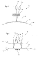
- FIG. 1 shows a schematic representation of a basic embodiment of an apparatus 10 for measuring the thickness of a sheet or web-like product 12, which may be, for example, a particular moving material web such as in particular a paper or board web.
- This preferred embodiment includes movable probes 14 on the two product sides with air cushions 16 to avoid contact with the product 12.
- the probes 14 are pressed against the product 12 with regulated force.
- the force in question can be generated in different ways, e.g. a compressed air operation, an operation on the torque of a motor, a magnetic actuation, etc. is conceivable.
- the sensor measures the thickness of the total measuring gap by means of a coil and a ferrite core on one side of the product and a passive ferrite disk on the other side of the product.
- the active coil can be arranged either on the upper or on the lower measuring head.
- This part of the sensor is the same as one conventional thickness sensor such as in EP 0299716 described.
- the total magnetic measurement gap using this method is the product thickness plus the two air cushions, which are typically less than 0.5 mm. This gap can be measured very accurately. Many other methods of measuring the thickness of the total gap are possible.
- a laser triangulation method is used to measure the air cushion thickness on both sides of the sheet or sheet product. This measurement can also be very accurate.
- the in the FIG. 1 shown linear array of detectors can be replaced by other types of position detectors.
- the lasers used are preferably blue or violet laser diodes, which rather generate small measuring points. Shortwave light is also advantageous because the penetration depth into the product is low.
- the lasers provided on the various product pages are clocked at different times to avoid crosstalk.
- the product thickness is calculated by subtracting the air cushion thicknesses from the total gap thickness.
- the air cushioning stabilizes the sheet or web shaped product and keeps the probes and product parallel to each other so that errors in sensor alignment are eliminated or greatly reduced.
- the sensor may be compensated for alignment.
- the sheet product may not be exactly parallel to the probes, which may, for example, be due to a greater curvature of the sheet, although air cushioning will greatly reduce deviations.
- the sheet or web-shaped product or the relevant material web is normally completely straight due to the sheet or web tension.
- the transverse direction however, the product may be undulating and some of this ripple may still be exist within the air cushion.
- the sensor may include two or more triangulation-based laser sensors on at least one product side to measure not only the distance to the product, but also the angle between the product and the probes, either only in the transverse direction , or both transversely and in the machine direction.
- the misalignment between the upper and lower probes is measured by placing small receiver coils on one product side and a transmit coil on the opposite product side.
- Another way to measure the lateral misalignment is to provide a permanent magnet on one product side and Hall sensors on the other side.
- There are several alternative methods of measuring lateral misalignment If the angle between the sheet-like product and the sensor in both the x and y directions and the amount of misalignment in the x and y directions are known, a correction value for the thickness measurement can be calculated.
- a laser measurement of the air cushion thicknesses can be used to control and / or regulate either the flow to the air cushions or the actuation force that presses the air cushion or sensor against the product to stabilize the air cushions at a particular thickness.
- This allows the use of simple segmented photodetectors instead of complete detector arrays.
- the segmented detectors are very small and easily deployable in a miniaturized optical design. They are available with either two or four elements with a very narrow nip separating the elements.
- the air cushion may be divided into segments in the x and y directions, with independent laser measurements of air cushion thickness and the like Controls and / or regulations for the air cushion thickness are possible. In this way, the air cushion thickness can be kept constant across the sensor in both the x and y directions on both sides of the product (the probes are held parallel to the product surface).
- the total gap is regulated to a constant value. This can be achieved, for example, by measuring the total gap by means of one or more total gap sensors or one or more laser sensors on each side of the product in order to perform the air cushion thickness measurement. A feedback from the total gap sensor can be used to control the air cushion thicknesses to keep the total gap constant. With multiple gap sensors and air cushion controls (flow control or force control), the probes can also be kept parallel to each other.
- air cushions are provided on both sides of the product, as described above. Further possible embodiments result in particular from the claims.
- the measuring device combines the currently achievable only with touching sensors accuracy with the advantages of an air cushion sensor.
- the thickness d of the sheet-like product 12 may be in a range of about 100 to about 200 ⁇ m.
- air cushion openings 18 can also be seen, via which a respective air cushion 16 can be generated.
- an upper laser source 20 and a lower laser source 22 can be seen in each case.
- the respective window for the upper laser source 20 is denoted by 24 and the respective window for the lower laser source 22 by "26".
- the provided on the lower product side ferrite is each provided with the reference numeral "28".
- FIG. 2 shows a schematic representation of an embodiment of the measuring device 10 with provided on both product pages lasers 34 and position sensors 36.
- an active core 38 with coil for the gap sensor can be seen on the top of the product 12.
- a passive ferrite disk 40 is arranged for the gap sensor.
- an air cushion 16 is again provided in each case.
- the measuring sensors 14 provided on the two product sides are pressed against the product 12 to form the respective air cushion 16.
- the sensors 14 provided on the two product sides can be pressed against the product 12, for example with at least substantially the same force, which, however, is by no means compulsory.
- the forces can also be different.
- the thickness of the respective air cushion 16 is measurable. Moreover, the thickness of both air cushions 16 and the product thickness d (cf. FIG. 1 ) comprehensive total gap thickness measurable. In addition, funds for Calculating the product thickness d by subtracting the thickness of the air cushion 16 provided on the two product sides of the measured total gap thickness.
- FIG. 3 shows a schematic representation of another embodiment of the measuring device 10, in which a plurality of sensors are provided to measure the total gap thickness to measure and compensate for the errors that have arisen due to an uneven gap between the probes.
- gap sensors 33 are again provided, which according to the illustration in accordance with FIG. 2
- each may comprise an active core 38 with associated coil and on the opposite product side a passive ferrite disk 40.
- one transmitting coil 42 can be provided on one product side and one or more receiving coils 44 for determining deviations in the xy direction on the other product side.
- FIG. 4 shows a schematic representation of another embodiment of the measuring device 10, in which the sheet or web-shaped product 12 is pressed against a roller 46. On the product side facing away from the roller 46, a laser 34 and a position sensor 36 is again provided. For measuring the total gap thickness, an eddy current sensor 48 is provided.
- FIG. 5 shows a schematic representation of another embodiment of the measuring device 10, in which the sheet or web-shaped product 12 is pressed against a fixed surface 50.
- one transmission coil 42 is arranged on one product side and one or more reception coils 44 on the other product side.
- FIG. 6 shows a schematic representation of another embodiment of the measuring device 10 with provided on both product pages fixed sensors 14th
- laser 34 and position sensor 36 are again provided on the two product pages.
- one transmitting coil 42 is provided on one side of the product and one or more receiving coils 46 are provided on the other side of the product.
- the sheet or web-shaped product 12 can thus be pressed against a stationary sensor 14 to form an air cushion 16.
- means for a laser measurement of the air cushion thickness on a product side and means for a laser measurement, in particular the distance from the sensor on the opposite product side to the product surface may be provided.
- means for measuring the total gap thickness and means for calculating the product thickness can again be provided by subtracting the laser measurement value from the measured value of the total gap thickness.
- FIG. 7 shows a schematic representation of another embodiment of the measuring device 10 with provided on both product pages fixed sensors.
- laser 34 and position sensor 36 are again provided on the two product pages.
- For inductive measurement of Total gap thickness can be provided on one side of the product again a transmitting coil 42 and on the other product side at least one receiving coil 44.
Landscapes
- Physics & Mathematics (AREA)
- General Physics & Mathematics (AREA)
- Length Measuring Devices By Optical Means (AREA)
- Length Measuring Devices With Unspecified Measuring Means (AREA)
- Measurement Of Length, Angles, Or The Like Using Electric Or Magnetic Means (AREA)
- A Measuring Device Byusing Mechanical Method (AREA)
Applications Claiming Priority (2)
| Application Number | Priority Date | Filing Date | Title |
|---|---|---|---|
| DE10361161A DE10361161A1 (de) | 2003-12-22 | 2003-12-22 | Messvorrichtung |
| EP04106408A EP1548398A1 (fr) | 2003-12-22 | 2004-12-09 | Dispositif pour la mesure de l'épaisseur d'une bande en mouvement |
Related Parent Applications (1)
| Application Number | Title | Priority Date | Filing Date |
|---|---|---|---|
| EP04106408.0 Division | 2004-12-09 |
Publications (2)
| Publication Number | Publication Date |
|---|---|
| EP2270422A2 true EP2270422A2 (fr) | 2011-01-05 |
| EP2270422A3 EP2270422A3 (fr) | 2011-08-24 |
Family
ID=34530397
Family Applications (2)
| Application Number | Title | Priority Date | Filing Date |
|---|---|---|---|
| EP04106408A Withdrawn EP1548398A1 (fr) | 2003-12-22 | 2004-12-09 | Dispositif pour la mesure de l'épaisseur d'une bande en mouvement |
| EP10186128A Withdrawn EP2270422A3 (fr) | 2003-12-22 | 2004-12-09 | Dispositif pour la mesure de l'épaisseur d'une bande en mouvement |
Family Applications Before (1)
| Application Number | Title | Priority Date | Filing Date |
|---|---|---|---|
| EP04106408A Withdrawn EP1548398A1 (fr) | 2003-12-22 | 2004-12-09 | Dispositif pour la mesure de l'épaisseur d'une bande en mouvement |
Country Status (3)
| Country | Link |
|---|---|
| US (1) | US7319521B2 (fr) |
| EP (2) | EP1548398A1 (fr) |
| DE (1) | DE10361161A1 (fr) |
Cited By (1)
| Publication number | Priority date | Publication date | Assignee | Title |
|---|---|---|---|---|
| CN104136884A (zh) * | 2011-12-28 | 2014-11-05 | 美卓自动化有限公司 | 待测对象的测量 |
Families Citing this family (20)
| Publication number | Priority date | Publication date | Assignee | Title |
|---|---|---|---|---|
| DE502005003829D1 (de) * | 2005-01-13 | 2008-06-05 | Plast Control Gmbh | Vorrichtung und Verfahren zur kapazitiven Vermessung von Materialien |
| US20070263228A1 (en) * | 2006-05-12 | 2007-11-15 | Voith Paper Patent Gmbh | Device and process for optical distance measurement |
| US7768629B2 (en) | 2006-05-12 | 2010-08-03 | Voith Patent Gmbh | Device and process for optical distance measurement |
| CN101868689B (zh) * | 2007-08-31 | 2016-11-02 | Abb有限公司 | 幅片厚度测量设备 |
| US9045306B2 (en) * | 2007-11-27 | 2015-06-02 | Abb Ltd. | Sheet stabilizer with suction nozzle having center protrusion |
| DE102008006720A1 (de) * | 2008-01-30 | 2009-08-06 | Dr. Schenk Gmbh Industriemesstechnik | Vorrichtung zur Bestimmung der Tiefe eines Fehlers in einem Bahnmaterial |
| WO2010104466A1 (fr) * | 2009-03-12 | 2010-09-16 | Daprox Ab | Procédés et moyens de mesurer sans contact l'épaisseur d'un revêtement non métallique sur une surface de matrice métallique |
| DE102011107771B4 (de) * | 2011-04-15 | 2013-10-17 | Micro-Epsilon Messtechnik Gmbh & Co. Kg | Vorrichtung und Verfahren zur Dickenmessung eines Messobjekts |
| WO2013007864A1 (fr) * | 2011-07-08 | 2013-01-17 | Metso Automation Oy | Procédé et dispositif de mesure destinés à mesurer l'épaisseur d'une bande fibreuse mobile |
| EP2708483B1 (fr) * | 2012-09-17 | 2015-09-23 | Roland Electronic GmbH | Procédé et dispositif destinés à détecter des pièces en double |
| FI125811B (en) * | 2013-05-29 | 2016-02-29 | Valmet Automation Oy | Track measurement |
| US9482523B2 (en) * | 2013-07-11 | 2016-11-01 | Lg Chem, Ltd. | Air micrometer |
| KR20150007578A (ko) * | 2013-07-11 | 2015-01-21 | 주식회사 엘지화학 | 에어 마이크로미터 |
| US9291573B2 (en) * | 2013-12-03 | 2016-03-22 | Pfm Integrators Inc. | Laser inspection system and methods |
| US9527320B2 (en) * | 2015-04-23 | 2016-12-27 | Xerox Corporation | Inkjet print head protection by acoustic sensing of media |
| US10240911B2 (en) | 2017-06-12 | 2019-03-26 | Advanced Gauging Technologies, LLC | Laser gauge with full air gap measurement range |
| SE543802C2 (en) * | 2019-12-20 | 2021-07-27 | Stora Enso Oyj | Method for determining film thickness, method for producing a film and device for producing a film |
| SE543843C2 (en) * | 2019-12-20 | 2021-08-10 | Stora Enso Oyj | Method for identifying defects in a film, method and device for producing a film |
| US11519710B2 (en) * | 2020-02-26 | 2022-12-06 | Honeywell Limited | High accuracy and high stability magnetic displacement sensor in the presence of electromagnetic interferences |
| CN114132512B (zh) * | 2022-02-07 | 2022-04-29 | 中国空气动力研究与发展中心低速空气动力研究所 | 一种光纤结冰传感器探头及调节方法 |
Citations (1)
| Publication number | Priority date | Publication date | Assignee | Title |
|---|---|---|---|---|
| EP0299716A1 (fr) | 1987-07-15 | 1989-01-18 | Impact Systems, Inc. | Jauge de contact pour déplacer des feuilles |
Family Cites Families (19)
| Publication number | Priority date | Publication date | Assignee | Title |
|---|---|---|---|---|
| JPS5644803A (en) * | 1979-09-21 | 1981-04-24 | Bridgestone Corp | System measuring for thickness of nonmetallic sheet like object |
| US4276480A (en) * | 1979-09-28 | 1981-06-30 | Accuray Corporation | Sensor position independent material property determination using radiant energy |
| DE3523414A1 (de) * | 1985-06-29 | 1987-01-02 | Deuta Werke Gmbh | Verfahren und vorrichtung zum messen insbesondere der dicke oder breite von koerpern, insbesondere von platten, folien, strangprofilen oder dergleichen |
| FI83911C (fi) * | 1986-05-14 | 1992-01-10 | Tapio Technologies Oy | Foerfarande och anordning foer maetning av ett hinnartat eller skivlikt bands tjocklek. |
| US5010766A (en) * | 1989-11-30 | 1991-04-30 | Impact Systems, Inc. | Error compensation for measuring gauges |
| US5162661A (en) * | 1990-02-08 | 1992-11-10 | Pioneer Electronic Corporation | Position detector for maintaining a fixed distance between two objects |
| DE59006447D1 (de) * | 1990-11-19 | 1994-08-18 | Kugelfischer G Schaefer & Co | Dickenmessgerät. |
| DE4221031C2 (de) * | 1992-06-26 | 1995-08-24 | Voith Gmbh J M | Einrichtung zur Dickenmessung von dünnen fortbewegten Substraten |
| KR100323955B1 (ko) * | 1993-05-24 | 2002-11-18 | 가부시키가이샤 고마쓰 세이사쿠쇼 | 구부림각도검출장치및그것에사용하는직선추출장치및구부림각도검출위치설정장치 |
| DE4407215A1 (de) * | 1994-03-06 | 1995-09-07 | Robert Prof Dr Ing Massen | Optische Dickenmessung an dünnen Bahnen |
| IT1269734B (it) * | 1994-05-10 | 1997-04-15 | Aeonic Syst Italia Srl | Dispositivo per la misura in linea dello spessore di un foglio industriale continuo,basato su due testine tastatrici contrapposte senza contatto diretto per mezzo di cuscini d'aria,azionate da una spinta invariante di tipo gravimetrico |
| DE19511939C2 (de) * | 1995-03-31 | 2000-05-18 | Micro Epsilon Messtechnik | Sensor zur berührungslosen Dickenmessung an Folien |
| DE19632385A1 (de) * | 1995-07-20 | 1997-03-06 | Dieter Prof Dr Ing Wuestenberg | Schlauchfolien-Dickenmeßsystem |
| US5714763A (en) * | 1996-03-25 | 1998-02-03 | Measurex Corporation | Method and apparatus for optical alignment of a measuring head in an X-Y plane |
| US6281679B1 (en) | 1998-12-21 | 2001-08-28 | Honeywell - Measurex | Web thickness measurement system |
| DE19913928B4 (de) * | 1999-03-26 | 2015-06-11 | Voith Patent Gmbh | Vorrichtung zum Bestimmen von Eigenschaften einer laufenden Materialbahn |
| DE10205985A1 (de) * | 2001-03-06 | 2002-09-19 | Heidelberger Druckmasch Ag | Bedruckstoffleitelement mit integriertem Abstandssensor |
| FI114337B (fi) * | 2001-07-03 | 2004-09-30 | Metso Automation Oy | Menetelmä ja mittalaite liikkuvan rainan ainakin yhden ominaisuuden mittaamiseksi |
| US6588118B2 (en) * | 2001-10-10 | 2003-07-08 | Abb Inc. | Non-contact sheet sensing system and related method |
-
2003
- 2003-12-22 DE DE10361161A patent/DE10361161A1/de not_active Withdrawn
-
2004
- 2004-12-09 EP EP04106408A patent/EP1548398A1/fr not_active Withdrawn
- 2004-12-09 EP EP10186128A patent/EP2270422A3/fr not_active Withdrawn
- 2004-12-22 US US11/024,331 patent/US7319521B2/en not_active Expired - Fee Related
Patent Citations (1)
| Publication number | Priority date | Publication date | Assignee | Title |
|---|---|---|---|---|
| EP0299716A1 (fr) | 1987-07-15 | 1989-01-18 | Impact Systems, Inc. | Jauge de contact pour déplacer des feuilles |
Cited By (2)
| Publication number | Priority date | Publication date | Assignee | Title |
|---|---|---|---|---|
| CN104136884A (zh) * | 2011-12-28 | 2014-11-05 | 美卓自动化有限公司 | 待测对象的测量 |
| CN104136884B (zh) * | 2011-12-28 | 2017-06-09 | 维美德自动化有限公司 | 待测对象的测量 |
Also Published As
| Publication number | Publication date |
|---|---|
| DE10361161A1 (de) | 2005-07-21 |
| US7319521B2 (en) | 2008-01-15 |
| EP1548398A1 (fr) | 2005-06-29 |
| EP2270422A3 (fr) | 2011-08-24 |
| US20050157314A1 (en) | 2005-07-21 |
Similar Documents
| Publication | Publication Date | Title |
|---|---|---|
| EP2270422A2 (fr) | Dispositif pour la mesure de l'épaisseur d'une bande en mouvement | |
| DE112008002244B4 (de) | Bahndickenmessgerät | |
| EP2210078B1 (fr) | Procédé pour déterminer la pression et la profondeur de sculpture d'un pneumatique de véhicule | |
| EP0293576B1 (fr) | Procédé d'acquisition des fautes dimensionnelles | |
| DE60214287T2 (de) | Methode und Messvorrichtung für das Messen von wenigstens einer Eigenschaft eines bewegten Bandes | |
| EP2449338B1 (fr) | Procédé et dispositif destinés à la détermination sans contact de l'épaisseur d'une bande de matériau avec correction du défaut d'alignement | |
| DE3642377A1 (de) | Verfahren und vorrichtung zur abmessung der dicke einer folien- oder blattartigen materialbahn | |
| EP2344286B1 (fr) | Procédé et dispositif de détermination d'une planéité d'un ruban métallique | |
| DE2057798A1 (de) | Geraet zum Pruefen von Materialbahnen | |
| DE3407258A1 (de) | Verfahren und vorrichtung zur bestimmung der genauen stellung eines beweglichen glieds | |
| EP2064532A1 (fr) | Système pour déterminer la pression dans un pneumatique de véhicule et/ou la vitesse du véhicule | |
| EP2839951A1 (fr) | Dispositif de fabrication d'une bande de carton ondulé contrecollé au moins sur une face | |
| EP0467117B1 (fr) | Dispositif pour mesurer l'épaisseur et/ou l'irrégularité d'une couche de fibres ou d'ouates dans les machines de préparation des métiers à filer | |
| EP2113608A2 (fr) | Dispositif de racloir et dispositif de raclage | |
| DE212015000052U1 (de) | Vorrichtung zur Messung der Dicke eines bewegten Bahnmaterials | |
| DE19832871C1 (de) | Verfahren und Vorrichtung zum Längsschneiden einer Materialbahn | |
| DE112009001353T5 (de) | Verfahren zum Kalibrieren der Position von Klingen eines Rollenschneiders in einer Faserbahnmaschine und das Verfahren anwendende Vorrichtung | |
| WO1987006334A1 (fr) | Dispositif pour mesurer l'epaisseur du papier ou similaire | |
| DE3220093A1 (de) | Einrichtung zur farbdichtemessung an laufenden, bahnfoermigen druckmaterialien | |
| DE102012112570B4 (de) | Messung der Materialstärke breiter Folien | |
| DE19913928B4 (de) | Vorrichtung zum Bestimmen von Eigenschaften einer laufenden Materialbahn | |
| WO2006128661A1 (fr) | Dispositif pour produire un produit intermediaire ou le produit final pour fabriquer des plaques a base de bois | |
| EP2449339A1 (fr) | Procédé de détermination sans contact de l'épaisseur d'une bande de matériau | |
| DE4111424A1 (de) | Verfahren und vorrichtung zur welligkeitsmessung | |
| WO1997036031A1 (fr) | Dispositif pour mesurer l'epaisseur et/ou l'inegalite d'ouates ou de non-tisses |
Legal Events
| Date | Code | Title | Description |
|---|---|---|---|
| PUAI | Public reference made under article 153(3) epc to a published international application that has entered the european phase |
Free format text: ORIGINAL CODE: 0009012 |
|
| AC | Divisional application: reference to earlier application |
Ref document number: 1548398 Country of ref document: EP Kind code of ref document: P |
|
| AK | Designated contracting states |
Kind code of ref document: A2 Designated state(s): AT BE BG CH CY CZ DE DK EE ES FI FR GB GR HU IE IS IT LI LT LU MC NL PL PT RO SE SI SK TR |
|
| RIN1 | Information on inventor provided before grant (corrected) |
Inventor name: ISCHDONAT, THOMAS Inventor name: TYPPOE, PEKKA Inventor name: SHEAD, RAY Inventor name: MUENCH, RUDOLF |
|
| RIN1 | Information on inventor provided before grant (corrected) |
Inventor name: ISCHDONAT, THOMAS Inventor name: TYPPOE, PEKKA Inventor name: MUENCH, RUDOLF Inventor name: SHEAD, RAY |
|
| RIN1 | Information on inventor provided before grant (corrected) |
Inventor name: SHEAD, RAY Inventor name: ISCHDONAT, THOMAS Inventor name: MUENCH, RUDOLF Inventor name: TYPPOE, PEKKA |
|
| PUAL | Search report despatched |
Free format text: ORIGINAL CODE: 0009013 |
|
| AK | Designated contracting states |
Kind code of ref document: A3 Designated state(s): AT BE BG CH CY CZ DE DK EE ES FI FR GB GR HU IE IS IT LI LT LU MC NL PL PT RO SE SI SK TR |
|
| RIC1 | Information provided on ipc code assigned before grant |
Ipc: G01B 11/06 20060101AFI20110720BHEP Ipc: D21F 7/06 20060101ALI20110720BHEP |
|
| STAA | Information on the status of an ep patent application or granted ep patent |
Free format text: STATUS: THE APPLICATION IS DEEMED TO BE WITHDRAWN |
|
| 18D | Application deemed to be withdrawn |
Effective date: 20120225 |