EP2269913A1 - Envelope for packaging and protection of a container, consisting of a thermoretractable plastic shell - Google Patents
Envelope for packaging and protection of a container, consisting of a thermoretractable plastic shell Download PDFInfo
- Publication number
- EP2269913A1 EP2269913A1 EP10161913A EP10161913A EP2269913A1 EP 2269913 A1 EP2269913 A1 EP 2269913A1 EP 10161913 A EP10161913 A EP 10161913A EP 10161913 A EP10161913 A EP 10161913A EP 2269913 A1 EP2269913 A1 EP 2269913A1
- Authority
- EP
- European Patent Office
- Prior art keywords
- sleeve
- packaging
- film
- opaque
- window area
- Prior art date
- Legal status (The legal status is an assumption and is not a legal conclusion. Google has not performed a legal analysis and makes no representation as to the accuracy of the status listed.)
- Granted
Links
Images


Classifications
-
- B—PERFORMING OPERATIONS; TRANSPORTING
- B65—CONVEYING; PACKING; STORING; HANDLING THIN OR FILAMENTARY MATERIAL
- B65D—CONTAINERS FOR STORAGE OR TRANSPORT OF ARTICLES OR MATERIALS, e.g. BAGS, BARRELS, BOTTLES, BOXES, CANS, CARTONS, CRATES, DRUMS, JARS, TANKS, HOPPERS, FORWARDING CONTAINERS; ACCESSORIES, CLOSURES, OR FITTINGS THEREFOR; PACKAGING ELEMENTS; PACKAGES
- B65D23/00—Details of bottles or jars not otherwise provided for
- B65D23/08—Coverings or external coatings
- B65D23/0842—Sheets or tubes applied around the bottle with or without subsequent folding operations
- B65D23/0878—Shrunk on the bottle
-
- B—PERFORMING OPERATIONS; TRANSPORTING
- B65—CONVEYING; PACKING; STORING; HANDLING THIN OR FILAMENTARY MATERIAL
- B65D—CONTAINERS FOR STORAGE OR TRANSPORT OF ARTICLES OR MATERIALS, e.g. BAGS, BARRELS, BOTTLES, BOXES, CANS, CARTONS, CRATES, DRUMS, JARS, TANKS, HOPPERS, FORWARDING CONTAINERS; ACCESSORIES, CLOSURES, OR FITTINGS THEREFOR; PACKAGING ELEMENTS; PACKAGES
- B65D25/00—Details of other kinds or types of rigid or semi-rigid containers
- B65D25/54—Inspection openings or windows
- B65D25/56—Inspection openings or windows with means for indicating level of contents
Definitions
- the present invention relates to the packaging and protection of objects, and more particularly of containers, by means of an envelope constituted by a sleeve of heat-shrinkable plastic material intended to be retracted on the container.
- the technique of packaging objects from a heat-shrinkable film made in the form of a sleeve has been used for thirty years, which is threaded onto the object or objects to be packaged and then heat-shrunk onto these objects.
- the sleeve is obtained from a film which is folded on itself and closed by joining the two end areas concerned.
- EP-1 790 578 A1 discloses a rotating heat-shrinkable plastic sleeve having one or two windows to distinguish indicia on the outer surface of the wrapped container.
- the object of the invention is to design a packaging and protective envelope for a container using the perfectly controlled technique of heat-shrinking a sleeve on said container, and allowing, without breaking the protection of the product present in the container. against light radiation, a visual inspection from the outside, at least during the use of said product.
- a packaging envelope and protection of a container constituted by a heat-shrinkable plastic sleeve. intended to be retracted onto the container, said sleeve being obtained from a film folded on itself and closed by joining the two end regions concerned, said envelope being remarkable in that the film constituting the sleeve is opaque to light on its entire surface except for a window area, and the aforementioned window area is covered, on the outer face of the sleeve, with a detachable adhesive strip which is opaque to light, the removal said adhesive strip giving access to the window area and allowing a direct visual observation of the product present inside the container.
- the constituent film of the sleeve is a white film in the mass, coated, on its face which is intended to form the inner face of said sleeve, with an opaque agent layer conferring on said film a property barrier to light.
- the window area is constituted by a coating interruption zone in the opaque agent layer.
- the area coating interruption is arranged to form a narrow slit.
- the constituent film of the sleeve is an opaque film in the mass, material having a light barrier property.
- the window area is constituted by a cutout made in the wall of the sleeve, said cutout defining at least one through opening.
- the cutout is arranged to form a narrow slot.
- the window area is constituted by at least one line of microperforations made in the wall of the sleeve, said at least one line of microperforations defining a through opening after removal of the area concerned.
- the line of microperforations is arranged to form a narrow slot.
- the detachable adhesive strip is in addition a tear strip, the removal of said strip realizing at the same time the access to the window area and removal of the area concerned. This then allows an overall removal in a single gesture perfectly ergonomic to access the window area.
- the aforementioned narrow slot extends along a generatrix of the sleeve, or alternatively extends circumferentially over at least part of the periphery of the sleeve.
- the detachable adhesive strip it can be provided that it is made from a white film in the mass, coated on its face which is turned towards the outer face of the sleeve, an opaque agent layer giving said strip a light barrier property.
- the detachable adhesive strip may be made from a film opaque in the mass, material having a light barrier property.
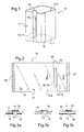
- the figure 1 illustrates a packaging and protective envelope of a container, which is constituted by a sleeve 10 of heat-shrinkable plastic material intended to be retracted onto the container.
- the sleeve 10 is obtained from a film folded on itself, denoted 11, which is closed by securing, for example by heat sealing, of the two end areas concerned at a generatrix line 12.
- the outer face of the sleeve is denoted 11.1, and the inner face of said sleeve is denoted 11.2.
- the constituent film of the sleeve 10 is opaque to light over its entire surface except for a window area 13, and this window area 13 is covered, on the outer face 11.1 of the sleeve 10, by a detachable adhesive strip 14 which is opaque to light, the removal of said adhesive strip giving access to the window area 13 and allowing a direct visual observation of the product present inside the container.
- the flat view of the figure 2 makes it possible to distinguish the wall 11 of the constituent film of the aforementioned sleeve 10, with its two end zones 12 'and 12 "which are normally in mutual overlap and in the sealing state before the sleeve is put in place on the container concerned .
- the constituent film of the sleeve 10 may be a white film in the mass, coated, on its face which is intended to constitute the inner face 11.2 of the sleeve, a layer of opaque agent conferring auditory film a light barrier property.
- This mode of execution is illustrated in Figures 3a and 3c , where the layer of opaque agent coating the inner face of the film 11 constituting the sleeve was noted.
- the opaque agent may be of different colors (black, silver, gold).
- the constituent film of the sleeve 10 may be an opaque film in the mass, material having a light barrier property. This variant is illustrated on the section of the figure 3b .
- this window area is formed by a cut in the wall of the sleeve 10, said cutout defining then at least one through opening.
- This possibility is illustrated on the Figures 3a and 3b , where there is a cutout 13 which is made in the wall of the film 11 constituting the sleeve, and which defines a through opening 18.
- the through opening in question is here arranged in the form of a narrow slot, which slot extends in this case along a generatrix of the sleeve 10.
- the detachable adhesive tape 14 it has been said that it must be opaque to light.
- the film constituting the sleeve we can then provide to organize the opacity in the light of the detachable adhesive strip 14 is with a strip made from a white film in the mass, coated, on its side which is turned towards the outer face of the sleeve 10, d a layer of opaque agent imparting to said strip a light barrier property, as illustrated in FIG. Figure 3a or 3c said opaque agent layer being denoted 17, or alternatively with a strip made from an opaque film in the mass, of material having a light barrier property, as illustrated on FIG. figure 3b .
- this face is in any case always coated with an adhesive (not shown on the figures) allowing its attachment to the wall of the constituent film of the sleeve, in overlap of the aforementioned window area 13 or 13 '.
- the covering of the window area 13 or 13 'by the detachable adhesive strip 14 is very important in this case, because it is it that guarantees the preservation of the barrier against light radiation, and therefore the protection of the product present in the container. Therefore, for safety reasons, it will generally provide a detachable adhesive tape sizing slightly greater than that of the window area concerned.
- a narrow slot 18 or 18 ' of rectangular shape, whose width will be for example of the order of 5 millimeters, and the height will be for example 50 to 60% of the height of the sleeve.
- the detachable adhesive strip 14 will for example have a width of 8 millimeters in order to guarantee a lateral covering over the entire height of the slot, and a height which may concern the entire height of the sleeve, as this is illustrated here, with then a protruding projecting end 15 which facilitates the removal of said band.
- a container 1 which can be a bottle, a bottle, or any type of container from the food, pharmaceutical, or medical field.
- the detachable adhesive strip 14 completely masks the window area 13 or 13 ', so that the protection of the product present in the container 1 against light radiation is total.
- the adhesive strip 14 has just been removed, which gives access to the aforementioned window area, with the definition of a narrow slot 18 or 18 'which allows a direct visual observation of the product present inside the container, and therefore a control either of the level of said product, of the presence thereof, or of the correct mixing thereof.
- the narrow slot 18 or 18 ' which has just been described here has the shape of a thin rectangle arranged in height (according to a generatrix of the sleeve), but it goes without saying that one can provide other forms, or other variants in which the cutting of the wall, where the area of interruption of the coating in the opaque agent layer, defines a plurality of small window areas, for example, in a succession of dots or dashes (variants not shown here).
- the window zone was constituted either by a cut-out made in the wall of the sleeve 10 or by a zone of interruption of the coating in the layer of opaque agent coating the internal face. said sleeve.
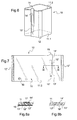
- Such a variant is illustrated in Figures 6 to 10 .
- the packaging and protective envelope differs from that just described with reference to Figures 1 to 5 in that the window area is constituted by at least one line of microperforations 13 "made in the wall of the sleeve 10, said at least one line of microperforations defining a through opening 18" after removal of the relevant area 19 ".
- the presence of the detachable adhesive strip 14 ' whose primary function is to cover the window area 13 "in order to preserve the opacity to light, provides an immediately available means for effecting the removal of the affected area 19" delimited the detachable adhesive strip 14 'is advantageously in addition a tear strip, the removal of said strip simultaneously providing access to the window area 13 "and the removal of the relevant area 19 "above, this is illustrated in the Figures 9 and 10 the heat-shrunk shell 10 is distinguished on the container 1, respectively before and after removal of the releasable adhesive strip 14 'which is additionally a tear strip.
- the narrow slot 18 " which here extends along a generatrix of the sleeve 10, may be made in the form of a plurality of windows, for example, a line consisting of circular dotted lines or dashes.
- the detachable adhesive strip 14 ' which is opaque to light, can be made from a white film in the mass, coated, on its face which is turned towards the outer face of the sleeve 10, of a layer of opaque agent imparting to said strip a light barrier property, or alternatively be made from an opaque film in the mass, of material having a light barrier property.
- FIG. 11 to 13 there is illustrated another variant in which the window area 13, 13 ', 13 "and the detachable adhesive strip 14, 14', 14" which covers it, do not extend either along a generatrix of the sleeve 10, but circumferentially, on at least part of the periphery of the sleeve 10.
- the Figures 12 and 13 illustrate such an envelope retracted onto the container 1, respectively before and after removal of the detachable adhesive strip 14 or 14 '.
- the narrow slot 18, 18 ', 18 " which extends circumferentially, only relates to a portion of the periphery of the sleeve, for example a portion limited to a third or a quarter thereof.
- FIGS. Figures 14 to 16 provision may be made for an always circumferential arrangement, but for the entire periphery of the sleeve 10, as illustrated in FIGS. Figures 14 to 16 .
- FIGS. Figures 14 to 16 On the Figures 15 and 16 , one thus distinguishes such an envelope variant, respectively before and after removal of the detachable adhesive strip 14 or 14 '.
- the narrow slot 18, 18 ', 18 " which again extends in a circumferential direction, makes it possible to clear the entire circumference of the container in a 360 ° complete circular window.
- Such an alternative circumferential arrangement will rather be used for the visual inspection of the presence of the product or of the correct miscibility of said product. product. Indeed, when it comes to controlling the level of a product, liquid or powder, inside the container, it will be preferable to use an arrangement extending along a generatrix of the sleeve, in accordance with the modes of previously described with reference to the Figures 1 to 10 .
Abstract
Description
La présente invention concerne l'emballage et la protection d'objets, et plus particulièrement de conteneurs, au moyen d'une enveloppe constituée par un manchon en matière plastique thermorétractable destiné à être rétracté sur le conteneur.The present invention relates to the packaging and protection of objects, and more particularly of containers, by means of an envelope constituted by a sleeve of heat-shrinkable plastic material intended to be retracted on the container.
On utilise depuis une trentaine d'années la technique d'emballage d'objets à partir d'un film thermorétractable réalisé sous la forme d'un manchon, qui est enfilé sur le ou les objets à emballer puis thermorétracté sur ces objets. En général, le manchon est obtenu à partir d'un film qui est replié sur lui-même et fermé par solidarisation des deux zones d'extrémité concernées.The technique of packaging objects from a heat-shrinkable film made in the form of a sleeve has been used for thirty years, which is threaded onto the object or objects to be packaged and then heat-shrunk onto these objects. In general, the sleeve is obtained from a film which is folded on itself and closed by joining the two end areas concerned.
Pour illustrer cet arrière plan technologique, on pourra se reporter aux nombreux documents de brevet de la demanderesse, en particulier les documents
On pourra également se référer au document
L'arrière plan technologique est enfin illustré par le document
Dans plusieurs domaines, par exemple alimentaire, pharmaceutique ou médical, il est nécessaire de protéger le produit que renferme le conteneur des rayonnements lumineux, notamment les UV, et ce aussi bien dans le spectre du visible que de l'invisible, donc pour des longueurs d'onde allant jusqu'à 500 nm. On peut par exemple citer le domaine alimentaire avec les produits lactés, pour lesquels une barrière à la lumière est nécessaire afin de préserver la couleur, les composants vitaminés, et les propriétés organoleptiques des produits concernés. On peut également citer le domaine pharmaceutique ou médical, avec le conditionnement de produits de perfusion, de transfusion, ou de produits oncologiques. Il peut enfin également s'agir de produits à mélange extemporané.In several fields, for example food, pharmaceutical or medical, it is necessary to protect the product contained in the container light radiation, including UV, and this in both the spectrum of the visible than the invisible, so for lengths waveform up to 500 nm. We can for example mention the food field with dairy products, for which a barrier to light is necessary to preserve the color, vitamin components, and organoleptic properties of the products concerned. There may also be mentioned the pharmaceutical or medical field, with the packaging of infusion products, transfusion products, or oncological products. Finally, it can also be products with extemporaneous mixing.
Dans ces différents domaines, il peut s'avérer nécessaire de vouloir contrôler le niveau du produit dans le conteneur, ou la présence du produit, ou encore l'état d'un mélange de différents produits dont on veut vérifier la bonne miscibilité.In these different areas, it may be necessary to want to control the level of the product in the container, or the presence of the product, or the state of a mixture of different products whose proper miscibility is to be verified.
Malheureusement, les spécialistes sont confrontés à une difficulté, car il y a une antinomie entre la protection globale contre les rayonnements lumineux sur toute la surface latérale du conteneur, et la possibilité d'un contrôle visuel de présence de produit ou de niveau de produit dans ledit conteneur. A ce titre, il convient de noter qu'une ligne de microperforations définissant une fenêtre détachable suffirait à rompre la propriété de barrière à la lumière, et donc ne pourrait convenir.Unfortunately, there is a problem for specialists because there is an antinomy between the overall protection against light radiation on the entire lateral surface of the container, and the possibility of a visual check of product presence or product level in said container. As such, it should be noted that a line of microperforations defining a detachable window would be enough to break the light barrier property, and therefore could not be suitable.
L'invention a pour objet de concevoir une enveloppe d'emballage et de protection d'un conteneur mettant en oeuvre la technique parfaitement maîtrisée de thermorétraction d'un manchon sur ledit conteneur, et permettant, sans rompre la protection du produit présent dans le conteneur contre les rayonnements lumineux, un contrôle visuel par l'extérieur, au moins lors de l'utilisation dudit produit.The object of the invention is to design a packaging and protective envelope for a container using the perfectly controlled technique of heat-shrinking a sleeve on said container, and allowing, without breaking the protection of the product present in the container. against light radiation, a visual inspection from the outside, at least during the use of said product.
Le problème technique précité est résolu conformément à l'invention grâce à une enveloppe d'emballage et de protection d'un conteneur, constituée par un manchon en matière plastique thermorétractable destiné à être rétracté sur le conteneur, ledit manchon étant obtenu à partir d'un film replié sur lui-même et fermé par solidarisation des deux zones d'extrémité concernées, ladite enveloppe étant remarquable en ce que le film constitutif du manchon est opaque à la lumière sur la totalité de sa surface à l'exception d'une zone de fenêtre, et la zone de fenêtre précitée est recouverte, sur la face externe du manchon, par une bande adhésive détachable qui est opaque à la lumière, l'enlèvement de ladite bande adhésive donnant accès à la zone de fenêtre et permettant une observation visuelle directe du produit présent à l'intérieur du conteneur.The aforementioned technical problem is solved according to the invention thanks to a packaging envelope and protection of a container, constituted by a heat-shrinkable plastic sleeve. intended to be retracted onto the container, said sleeve being obtained from a film folded on itself and closed by joining the two end regions concerned, said envelope being remarkable in that the film constituting the sleeve is opaque to light on its entire surface except for a window area, and the aforementioned window area is covered, on the outer face of the sleeve, with a detachable adhesive strip which is opaque to light, the removal said adhesive strip giving access to the window area and allowing a direct visual observation of the product present inside the container.
Ainsi, tant que la bande adhésive est présente sur le manchon, la protection du produit contre les rayonnements lumineux, notamment les UV, reste totale sur toute la périphérie du manchon, et, dès que la bande adhésive est enlevée, en particulier lors de l'utilisation, on obtient un moyen simple pour permettre un contrôle visuel du niveau du produit, ou de la présence dudit produit, dans le conteneur.Thus, as long as the adhesive strip is present on the sleeve, protection of the product against light radiation, in particular UV, remains total over the entire periphery of the sleeve, and as soon as the adhesive strip is removed, in particular when use, a simple means is obtained to allow visual control of the level of the product, or the presence of said product, in the container.
En particulier, lorsqu'il s'agit de conteneurs contenant des produits lactés, tels que des biberons, il devient possible de contrôler en cours d'utilisation le niveau du liquide présent dans le conteneur, avec éventuellement même l'observation d'une graduation préalablement imprimée au voisinage de la zone de fenêtre.In particular, when it comes to containers containing milk products, such as baby bottles, it becomes possible to control in use the level of the liquid present in the container, possibly with even the observation of a graduation previously printed in the vicinity of the window area.
Dans un premier mode d'exécution, le film constitutif du manchon est un film blanc dans la masse, revêtu, sur sa face qui est destinée à constituer la face interne dudit manchon, d'une couche d'agent opaque conférant audit film une propriété barrière à la lumière.In a first embodiment, the constituent film of the sleeve is a white film in the mass, coated, on its face which is intended to form the inner face of said sleeve, with an opaque agent layer conferring on said film a property barrier to light.
On pourra alors prévoir que la zone de fenêtre est constituée par une zone d'interruption du revêtement dans la couche d'agent opaque. En particulier, la zone d'interruption de revêtement est agencée pour former une fente étroite.It can then be provided that the window area is constituted by a coating interruption zone in the opaque agent layer. In particular, the area coating interruption is arranged to form a narrow slit.
Conformément à un autre mode d'exécution, le film constitutif du manchon est un film opaque dans la masse, en matériau présentant une propriété barrière à la lumière.According to another embodiment, the constituent film of the sleeve is an opaque film in the mass, material having a light barrier property.
Dans l'un ou l'autre des cas, on pourra prévoir que la zone de fenêtre est constituée par une découpe pratiquée dans la paroi du manchon, ladite découpe définissant au moins une ouverture traversante. En particulier, la découpe est agencée pour former une fente étroite.In either case, it may be provided that the window area is constituted by a cutout made in the wall of the sleeve, said cutout defining at least one through opening. In particular, the cutout is arranged to form a narrow slot.
En variante, on pourra prévoir que la zone de fenêtre est constituée par au moins une ligne de microperforations pratiquée dans la paroi du manchon, ladite au moins une ligne de microperforations définissant une ouverture traversante après enlèvement de la zone concernée. En particulier, la ligne de microperforations est agencée pour former une fente étroite.Alternatively, it can be provided that the window area is constituted by at least one line of microperforations made in the wall of the sleeve, said at least one line of microperforations defining a through opening after removal of the area concerned. In particular, the line of microperforations is arranged to form a narrow slot.
Dans le cas d'une zone de fenêtre constituée par au moins une ligne de microperforations, il est particulièrement avantageux de prévoir que la bande adhésive détachable est en plus une bande d'arrachage, l'enlèvement de ladite bande réalisant en même temps l'accès à la zone de fenêtre et l'enlèvement de la zone concernée. Ceci permet alors un enlèvement d'ensemble en un geste unique parfaitement ergonomique pour accéder à la zone de fenêtre.In the case of a window area constituted by at least one line of microperforations, it is particularly advantageous to provide that the detachable adhesive strip is in addition a tear strip, the removal of said strip realizing at the same time the access to the window area and removal of the area concerned. This then allows an overall removal in a single gesture perfectly ergonomic to access the window area.
On pourra prévoir dans tous les cas que la fente étroite précitée s'étend selon une génératrice du manchon, ou en variante s'étend circonférentiellement, sur une partie au moins de la périphérie du manchon.It can be provided in all cases that the aforementioned narrow slot extends along a generatrix of the sleeve, or alternatively extends circumferentially over at least part of the periphery of the sleeve.
Pour ce qui est de la bande adhésive détachable, on pourra prévoir que celle-ci est réalisée à partir d'un film blanc dans la masse, revêtu, sur sa face qui est tournée vers la face externe du manchon, d'une couche d'agent opaque conférant à ladite bande une propriété barrière à la lumière.With regard to the detachable adhesive strip, it can be provided that it is made from a white film in the mass, coated on its face which is turned towards the outer face of the sleeve, an opaque agent layer giving said strip a light barrier property.
En variante, la bande adhésive détachable pourra être réalisée à partir d'un film opaque dans la masse, en matériau présentant une propriété barrière à la lumière.Alternatively, the detachable adhesive strip may be made from a film opaque in the mass, material having a light barrier property.
D'autres caractéristiques et avantages de l'invention apparaitront plus clairement à la lumière de la description qui va suivre et du dessin annexé.Other features and advantages of the invention will appear more clearly in the light of the description which follows and the accompanying drawing.
Il sera fait référence aux figures du dessin annexé, où :
- la
figure 1 est une vue en perspective illustrant une enveloppe d'emballage et de protection conforme à l'invention, avec sa bande adhésive détachable opaque à la lumière qui masque une zone de fenêtre ; - la
figure 2 est une vue en plan de la surface interne développée du manchon constitutif de l'enveloppe précitée ; - les
figures 3a, 3b, 3c sont des coupes selon III-III de lafigure 2 , qui illustrent différentes variantes de réalisation pour la zone de fenêtre et pour la bande adhésive détachable qui la recouvre ; - la
figure 4 illustre l'enveloppe d'emballage et de protection précitée thermorétractée sur un conteneur, et lafigure 5 le même ensemble après enlèvement de la bande adhésive détachable ; - la
figure 6 est une vue en perspective illustrant une variante de l'enveloppe d'emballage et de protection selon l'invention, dans laquelle la zone de fenêtre est constituée non plus par une découpe ou un enlèvement de revêtement opaque, mais par une ligne de microperforations, et dans laquelle aussi la bande adhésive détachable est en plus une bande d'arrachage ; - la
figure 7 est une vue en plan analogue à celle de lafigure 2 , pour la face interne développée de l'enveloppe de lafigure 6 ; - les
figures 8a et 8b sont des coupes selon VIII-VIII de lafigure 7 , qui illustrent deux variantes d'agencement avec des microperforations ; - les
figures 9 et 10 illustrent l'enveloppe d'emballage et de protection de lafigure 6 , thermorétractée sur un conteneur, respectivement avant et après enlèvement de la bande adhésive détachable qui est alors également une bande d'arrachage ; - la
figure 11 est une vue en perspective illustrant encore une autre variante, avec un agencement dans lequel la zone de fenêtre s'étend non plus selon une génératrice du manchon, mais circonférentiellement ; - les
figures 12 et 13 illustrent l'enveloppe d'emballage et de protection de lafigure 11 , thermorétractée sur un conteneur, respectivement avant et après enlèvement de la bande adhésive détachable ; - la
figure 14 illustre en perspective une variante de lafigure 11 , dans laquelle la zone de fenêtre qui s'étend circonférentiellement concerne non plus une partie, mais la totalité de la périphérie du manchon ; et - les
figures 15 et 16 illustrent l'enveloppe d'emballage et de protection de lafigure 14 , thermorétractée sur un conteneur, respectivement avant et après enlèvement de la bande adhésive détachable.
- the
figure 1 is a perspective view illustrating a packaging and protective envelope according to the invention, with its detachable adhesive tape opaque to light that masks a window area; - the
figure 2 is a plan view of the developed inner surface of the sleeve constituting the aforementioned envelope; - the
Figures 3a, 3b, 3c are cuts according to III-III of thefigure 2 , which illustrate different embodiments for the window area and for the detachable adhesive strip which covers it; - the
figure 4 illustrates the above-mentioned packaging and protective envelope heat-shrunk on a container, and thefigure 5 the same set after removal of the detachable adhesive tape; - the
figure 6 is a perspective view illustrating a variant of the packaging and protection envelope according to the invention, in which the window area is no longer constituted by a cut or removal of opaque coating, but by a line of microperforations, and wherein also the detachable adhesive tape is in addition a tear tape; - the
figure 7 is a plan view similar to that of thefigure 2 , for the developed inner side of the envelope of thefigure 6 ; - the
Figures 8a and 8b are cuts according to VIII-VIII of thefigure 7 , which illustrate two alternative arrangements with microperforations; - the
Figures 9 and 10 illustrate the packaging and protection envelope of thefigure 6 , heat-shrunk on a container, respectively before and after removal of the detachable adhesive tape which is then also a tear tape; - the
figure 11 is a perspective view illustrating yet another variant, with an arrangement in which the window area extends not further along a generatrix of the sleeve, but circumferentially; - the
Figures 12 and 13 illustrate the packaging and protection envelope of thefigure 11 heat-shrunk onto a container, respectively before and after removal of the releasable adhesive strip; - the
figure 14 illustrates in perspective a variant of thefigure 11 wherein the circumferentially extending window area is no longer a portion but the entire circumference of the sleeve; and - the
Figures 15 and 16 illustrate the packaging and protection envelope of thefigure 14 , heat-shrunk on a container, respectively before and after removal of the detachable adhesive tape.
La
Conformément à l'invention, le film constitutif du manchon 10 est opaque à la lumière sur la totalité de sa surface à l'exception d'une zone de fenêtre 13, et cette zone de fenêtre 13 est recouverte, sur la face externe 11.1 du manchon 10, par une bande adhésive détachable 14 qui est opaque à la lumière, l'enlèvement de ladite bande adhésive donnant accès à la zone de fenêtre 13 et permettant une observation visuelle directe du produit présent à l'intérieur du conteneur.According to the invention, the constituent film of the
La vue à plat de la
Ainsi que cela ressort des coupes des
Pour ce qui est de l'opacité à la lumière, le film constitutif du manchon 10 peut être un film blanc dans la masse, revêtu, sur sa face qui est destinée à constituer la face interne 11.2 du manchon, d'une couche d'agent opaque conférant audit film une propriété barrière à la lumière. Ce mode d'exécution est illustré aux
En variante, le film constitutif du manchon 10 peut être un film opaque dans la masse, en matériau présentant une propriété barrière à la lumière. Cette variante est illustrée sur la coupe de la
Pour ce qui est de la zone de fenêtre qui constitue une exception à la zone du manchon 10 qui est opaque à la lumière, on peut prévoir que cette zone de fenêtre est constituée par une découpe pratiquée dans la paroi du manchon 10, ladite découpe définissant alors au moins une ouverture traversante. Cette possibilité est illustrée sur les
Dans le cas de la présence d'un revêtement d'une face du film constitutif du manchon 10 au moyen d'une couche d'agent opaque 16 conférant audit film une propriété barrière à la lumière, on pourra prévoir une autre façon d'agencer la zone de fenêtre précitée, avec une zone de fenêtre constituée par une zone d'interruption du revêtement dans la couche d'agent opaque 16. Ceci est illustré sur la
Pour ce qui est de la bande adhésive détachable 14, on a dit que celle-ci doit être opaque à la lumière. Comme pour le film constitutif du manchon, on pourra alors prévoir d'organiser l'opacité à la lumière de la bande adhésive détachable 14 soit avec une bande réalisée à partir d'un film blanc dans la masse, revêtu, sur sa face qui est tournée vers la face externe du manchon 10, d'une couche d'agent opaque conférant à ladite bande une propriété barrière à la lumière, comme cela est illustré sur la
Le recouvrement de la zone de fenêtre 13 ou 13' par la bande adhésive détachable 14 est très important en l'espèce, car c'est lui qui garantit la préservation de la barrière contre les rayonnements lumineux, et donc la protection du produit présent dans le conteneur. De ce fait, pour des raisons de sécurité, on prévoira en général une bande adhésive détachable de dimensionnement légèrement supérieur à celui de la zone de fenêtre concernée. Sur les exemples illustrés ici, on est en présence d'une fente étroite 18 ou 18', de forme rectangulaire, dont la largeur sera par exemple de l'ordre de 5 millimètres, et la hauteur sera par exemple 50 à 60 % de la hauteur du manchon. Dans ce cas, la bande adhésive détachable 14 aura par exemple une largeur de 8 millimètres afin de garantir un recouvrement latéral sur toute la hauteur de la fente, et une hauteur qui peut concerner la totalité de la hauteur du manchon comme cela est illustré ici, avec alors une extrémité saillante de préhension 15 qui facilite l'enlèvement de ladite bande.The covering of the
Sur la
Sur la
Comme cela est illustré sur la
La fente étroite 18 ou 18' qui vient d'être décrite a ici la forme d'un mince rectangle disposé en hauteur (selon une génératrice du manchon), mais il va de soi que l'on pourra prévoir d'autres formes, ou encore d'autres variantes dans lesquelles la découpe de la paroi, où la zone d'interruption du revêtement dans la couche d'agent opaque, définit une pluralité de petites zones de fenêtre, par exemple, selon une succession de pointillés ou de tirets (variantes non illustrées ici).The
Dans les modes de réalisation qui viennent d'être décrits, la zone de fenêtre était constituée soit par une découpe pratiquée dans la paroi du manchon 10, soit par une zone d'interruption du revêtement dans la couche d'agent opaque revêtant la face interne dudit manchon. Il est cependant possible d'agencer encore autrement la zone de fenêtre précitée, tout en conservant les avantages précédemment décrits. Une telle variante est illustrée aux
Sur les
Là encore, on constate que la ligne de microperforations 13" est ici agencée pour former une fente étroite 18" qui est analogue aux fentes étroite 18, 18' précédemment décrites, mais ceci ne constitue qu'un exemple.Again, it is found that the line of
Comme cela est illustré sur les
La présence de la bande adhésive détachable 14', dont la fonction première est de recouvrir la zone de fenêtre 13" afin de préserver l'opacité à la lumière, procure un moyen immédiatement disponible pour réaliser l'enlèvement de la zone concernée 19" délimitée par la ligne de microperforations 13". Ainsi, la bande adhésive détachable 14' est avantageusement en plus une bande d'arrachage, l'enlèvement de ladite bande réalisant en même temps l'accès à la zone de fenêtre 13" et l'enlèvement de la zone concernée 19" précitée. Ceci est illustré sur les
Là encore, on peut prévoir une impression de graduations 50 sur la face extérieure du film, le long d'un bord vertical de la fente étroite 18" qui est formée par la ligne de microperforations 13", comme illustré sur la
Comme indiqué précédemment, la fente étroite 18", qui s'étend ici selon une génératrice du manchon 10, pourra être réalisée sous forme d'une pluralité de fenêtres, par exemple, une ligne constituée de pointillés circulaires ou de tirets.As indicated above, the
Dans le cas de la variante qui vient d'être illustrée en référence aux
Comme précédemment, la bande adhésive détachable 14', qui est opaque à la lumière, pourra être réalisée à partir d'un film blanc dans la masse, revêtu, sur sa face qui est tournée vers la face externe du manchon 10, d'une couche d'agent opaque conférant à ladite bande une propriété barrière à la lumière, ou en variante être réalisée à partir d'un film opaque dans la masse, en matériau présentant une propriété barrière à la lumière.As previously, the detachable adhesive strip 14 ', which is opaque to light, can be made from a white film in the mass, coated, on its face which is turned towards the outer face of the
Sur les
Sur les
On pourra en variante prévoir un agencement toujours circonférentiel, mais concernant la totalité de la périphérie du manchon 10, comme cela est illustré sur les
Une telle variante d'agencement circonférentiel sera plutôt utilisée pour le contrôle visuel de la présence du produit ou de la miscibilité correcte dudit produit. En effet, lorsqu'il s'agit de contrôler le niveau d'un produit, liquide ou pulvérulent, à l'intérieur du conteneur, il sera préférable d'utiliser un agencement s'étendant selon une génératrice du manchon, conformément aux modes de réalisation précédemment décrits en référence aux
On est ainsi parvenu à réaliser une enveloppe d'emballage et de protection d'un conteneur qui permet, sans nuire à la capacité de barrière à la lumière de la paroi, d'avoir une observation visuelle directe du produit présent à l'intérieur d'un conteneur.It has thus been possible to achieve a packaging envelope and protection of a container which allows, without impairing the light barrier capacity of the wall, to have a direct visual observation of the product present inside the container. 'a container.
Claims (14)
Priority Applications (1)
| Application Number | Priority Date | Filing Date | Title |
|---|---|---|---|
| PL10161913T PL2269913T3 (en) | 2009-06-30 | 2010-05-04 | Envelope for packaging and protection of a container, consisting of a thermoretractable plastic shell |
Applications Claiming Priority (1)
| Application Number | Priority Date | Filing Date | Title |
|---|---|---|---|
| FR0903177A FR2947251B1 (en) | 2009-06-30 | 2009-06-30 | ENVELOPE FOR PACKAGING AND PROTECTING A CONTAINER, CONSISTING OF A SLEEVE OF PLASTIC THERMORETRACTABLE MATERIAL |
Publications (2)
| Publication Number | Publication Date |
|---|---|
| EP2269913A1 true EP2269913A1 (en) | 2011-01-05 |
| EP2269913B1 EP2269913B1 (en) | 2014-10-15 |
Family
ID=41171257
Family Applications (1)
| Application Number | Title | Priority Date | Filing Date |
|---|---|---|---|
| EP10161913.8A Active EP2269913B1 (en) | 2009-06-30 | 2010-05-04 | Envelope for packaging and protection of a container, consisting of a thermoretractable plastic shell |
Country Status (10)
| Country | Link |
|---|---|
| US (1) | US7918342B2 (en) |
| EP (1) | EP2269913B1 (en) |
| CN (1) | CN101934878B (en) |
| BR (1) | BRPI1002144A2 (en) |
| DK (1) | DK2269913T3 (en) |
| ES (1) | ES2527677T3 (en) |
| FR (1) | FR2947251B1 (en) |
| MX (1) | MX2010007163A (en) |
| PL (1) | PL2269913T3 (en) |
| RU (1) | RU2435720C1 (en) |
Families Citing this family (14)
| Publication number | Priority date | Publication date | Assignee | Title |
|---|---|---|---|---|
| CN101360609A (en) * | 2005-12-05 | 2009-02-04 | 生命线细胞技术公司 | Cell culture medium container assembly |
| JP2011150615A (en) * | 2010-01-25 | 2011-08-04 | Hochiki Corp | Alarm system |
| FR2985506B1 (en) * | 2012-01-06 | 2014-03-14 | Novatec | RETRACTABLE ENVELOPE FOR DETECTING THE OPENING OF A CONTAINER |
| CN103043341A (en) * | 2012-12-27 | 2013-04-17 | 上海福将塑胶工业集团有限公司 | Packaging barrel with liquid level display function |
| FR3003549B1 (en) * | 2013-03-19 | 2015-04-10 | Sleever Int | SECURITY ENVELOPE FOR PROVIDING ANTI-OPENING PROTECTION OF CONTAINERS, OBJECT COVERED WITH SUCH AN ENVELOPE AND METHOD FOR REGISTERING INFORMATION ON SUCH AN ENVELOPE |
| US9371158B2 (en) | 2014-06-25 | 2016-06-21 | The Procter & Gamble Company | Liquid laundry product having a window for viewing |
| TW201641095A (en) | 2014-12-18 | 2016-12-01 | 健生藥品公司 | Vial holder devices, methods and systems |
| CN106542180A (en) * | 2016-11-09 | 2017-03-29 | 卢润侨 | A kind of beverage packaging box |
| CN106892222A (en) * | 2017-03-22 | 2017-06-27 | 中国人民解放军后勤工程学院 | Horizontal metal oil tank protective cover |
| JP7018732B2 (en) * | 2017-09-29 | 2022-02-14 | 株式会社フジシール | Heat shrinkable tubular label |
| JP7116903B2 (en) * | 2017-10-11 | 2022-08-12 | 大日本印刷株式会社 | Composite container and manufacturing method thereof, composite preform and manufacturing method thereof, and plastic member |
| JP6986959B2 (en) * | 2017-12-27 | 2021-12-22 | 株式会社吉野工業所 | Discharge container |
| WO2020091977A1 (en) * | 2018-10-31 | 2020-05-07 | The Procter & Gamble Company | Container with apertured shrink sleeve and related processes |
| US20210295744A1 (en) * | 2020-03-17 | 2021-09-23 | Multi-Color Corporation | Shrink sleeve label |
Citations (6)
| Publication number | Priority date | Publication date | Assignee | Title |
|---|---|---|---|---|
| DE883700C (en) | 1951-12-16 | 1953-07-20 | Fruchtsaft Ges M B H | Label or cover |
| WO1997028062A1 (en) * | 1996-02-02 | 1997-08-07 | Sleever International Company | Wrapper consisting of a heat-shrinkable plastic sleeve for packaging at least one object |
| WO2002000518A1 (en) * | 2000-06-30 | 2002-01-03 | Sleever International Company | Envelope for packaging at least an object, consisting of a heat-shrinkable plastic material sleeve |
| EP1082256B1 (en) | 1998-05-20 | 2004-12-08 | Sleever International Company | Safety envelope formed by a sleeve made in heat shrinkable material equipped with an identifying metal-coated strip |
| EP1790578A1 (en) | 2005-11-29 | 2007-05-30 | Inve Asia Services Limited | A container with a rotatable label comprising a transparent window |
| EP1513739B1 (en) | 2002-06-19 | 2007-08-15 | Sleever International Company | Wrap for packaging object(s) consisting of a shrinkable plastic material sleeve |
Family Cites Families (14)
| Publication number | Priority date | Publication date | Assignee | Title |
|---|---|---|---|---|
| US3312337A (en) * | 1966-03-21 | 1967-04-04 | Continental Can Co | Protective package for frangible articles |
| US3516537A (en) * | 1968-06-27 | 1970-06-23 | Grace W R & Co | Opening device on bags and the like |
| US3533501A (en) * | 1969-02-11 | 1970-10-13 | George L Dorsett | Windowed coin package |
| US3885671A (en) * | 1971-04-28 | 1975-05-27 | Gilbreth Co | Securement of band to card |
| US5605230A (en) * | 1994-10-11 | 1997-02-25 | Elr, Inc. | Sealed label having anti-counterfeit construction |
| US20030000862A1 (en) * | 2001-06-15 | 2003-01-02 | Martin Matushek | Container with windowed label |
| US6889483B2 (en) * | 2002-10-31 | 2005-05-10 | Cryovac, Inc. | Easy-opening feature for flexible packages and process and apparatus for forming same |
| US7543590B2 (en) * | 2004-06-30 | 2009-06-09 | Blunt Wrap U.S.A., Inc. | Intermediate wrapper and method of making |
| US7571810B2 (en) * | 2005-09-08 | 2009-08-11 | One Source Industries, Llc | Printed packaging |
| US20070059500A1 (en) * | 2005-09-09 | 2007-03-15 | The Procter & Gamble Company | Opaque printed substrate |
| WO2007052226A2 (en) * | 2005-11-01 | 2007-05-10 | The Procter & Gamble Company | Packaging for viewing visually distinct phases of a composition |
| CN2887766Y (en) * | 2006-03-27 | 2007-04-11 | 陈旺蓝 | Improved structure of adhesive bottle body |
| CA2577380A1 (en) * | 2007-02-06 | 2008-08-06 | Hood Packaging Corporation | Easy opening shrink wrapper for product bundle |
| CN201169412Y (en) * | 2007-09-03 | 2008-12-24 | 李雨菡 | Package excluding light with opening transparent view window |
-
2009
- 2009-06-30 FR FR0903177A patent/FR2947251B1/en not_active Expired - Fee Related
-
2010
- 2010-05-04 EP EP10161913.8A patent/EP2269913B1/en active Active
- 2010-05-04 PL PL10161913T patent/PL2269913T3/en unknown
- 2010-05-04 DK DK10161913.8T patent/DK2269913T3/en active
- 2010-05-04 ES ES10161913.8T patent/ES2527677T3/en active Active
- 2010-06-14 US US12/814,852 patent/US7918342B2/en not_active Expired - Fee Related
- 2010-06-22 BR BRPI1002144-2A patent/BRPI1002144A2/en not_active IP Right Cessation
- 2010-06-25 MX MX2010007163A patent/MX2010007163A/en active IP Right Grant
- 2010-06-29 CN CN2010102270971A patent/CN101934878B/en not_active Expired - Fee Related
- 2010-06-29 RU RU2010126627/13A patent/RU2435720C1/en not_active IP Right Cessation
Patent Citations (8)
| Publication number | Priority date | Publication date | Assignee | Title |
|---|---|---|---|---|
| DE883700C (en) | 1951-12-16 | 1953-07-20 | Fruchtsaft Ges M B H | Label or cover |
| WO1997028062A1 (en) * | 1996-02-02 | 1997-08-07 | Sleever International Company | Wrapper consisting of a heat-shrinkable plastic sleeve for packaging at least one object |
| EP0879189B1 (en) | 1996-02-02 | 1999-07-28 | Sleever International Company | Wrapper consisting of a heat-shrinkable plastic sleeve for packaging at least one object |
| EP1082256B1 (en) | 1998-05-20 | 2004-12-08 | Sleever International Company | Safety envelope formed by a sleeve made in heat shrinkable material equipped with an identifying metal-coated strip |
| WO2002000518A1 (en) * | 2000-06-30 | 2002-01-03 | Sleever International Company | Envelope for packaging at least an object, consisting of a heat-shrinkable plastic material sleeve |
| EP1294614B1 (en) | 2000-06-30 | 2004-08-18 | Sleever International Company | Envelope for packaging at least an object, consisting of a heat-shrinkable plastic material sleeve |
| EP1513739B1 (en) | 2002-06-19 | 2007-08-15 | Sleever International Company | Wrap for packaging object(s) consisting of a shrinkable plastic material sleeve |
| EP1790578A1 (en) | 2005-11-29 | 2007-05-30 | Inve Asia Services Limited | A container with a rotatable label comprising a transparent window |
Also Published As
| Publication number | Publication date |
|---|---|
| RU2435720C1 (en) | 2011-12-10 |
| FR2947251B1 (en) | 2012-11-16 |
| US7918342B2 (en) | 2011-04-05 |
| EP2269913B1 (en) | 2014-10-15 |
| US20100326867A1 (en) | 2010-12-30 |
| BRPI1002144A2 (en) | 2012-03-13 |
| DK2269913T3 (en) | 2015-01-19 |
| CN101934878A (en) | 2011-01-05 |
| FR2947251A1 (en) | 2010-12-31 |
| PL2269913T3 (en) | 2015-03-31 |
| CN101934878B (en) | 2012-11-28 |
| MX2010007163A (en) | 2011-01-05 |
| ES2527677T3 (en) | 2015-01-28 |
Similar Documents
| Publication | Publication Date | Title |
|---|---|---|
| EP2269913B1 (en) | Envelope for packaging and protection of a container, consisting of a thermoretractable plastic shell | |
| EP0929886B1 (en) | Security cover for objects, particularly for containers with closing device | |
| FR2576286A2 (en) | SPOLIATION WITNESS PACKAGING | |
| EP2718197B1 (en) | Stopping device and container comprising such a device | |
| EP1513739B1 (en) | Wrap for packaging object(s) consisting of a shrinkable plastic material sleeve | |
| CA2649461A1 (en) | Container closure, container equipped with same and method for making same | |
| EP3423368B1 (en) | Capsule made of heat-shrinkable plastic and use of the skirt of a capsule to form a drip-catching pouring spout | |
| FR2778892A1 (en) | Heat-shrinkable security sleeve for containers with opening tops | |
| EP2976272B1 (en) | Safety envelope capable of providing protection against opening of receptacles, object covered with an envelope of this type and method for affixing information on an envelope of this type | |
| FR2737188A1 (en) | ENVELOPE FOR PACKAGING AT LEAST ONE OBJECT, OF THE TYPE CONSISTING OF A SLEEVE OF HEAT-SHRINKABLE PLASTIC MATERIAL | |
| FR2540835A1 (en) | PACKAGING AND SAMPLE CLOSURE DEVICE FOR SPOLIATION | |
| FR2682935A1 (en) | Tamper indicator for packaging trays, trays including such an indicator and applications | |
| EP0879189B1 (en) | Wrapper consisting of a heat-shrinkable plastic sleeve for packaging at least one object | |
| FR2715131A1 (en) | Display assembly for packaged pharmaceutical tubes | |
| EP2687453A1 (en) | Packaging case with tamper-proof system | |
| FR2704206A1 (en) | Cardboard container with built-in spout | |
| FR2731982A1 (en) | Packaging container for biscuits | |
| EP2096045B1 (en) | Attachment ring for at least two stacked containers | |
| EP3318505B1 (en) | Safety casing and container covered with such a casing | |
| FR2803833A1 (en) | ENVELOPE FOR THE PACKAGING OF A SIDE-HANDLE BOTTLE OF THE TYPE CONSISTING OF A THERMORETRACTABLE PLASTIC SLEEVE | |
| FR2985506A1 (en) | Housing for covering portion of container and portion of closing unit i.e. lid, has adhesive seal, where characteristic of seal is impaired when seal is detached from wall of container after free surface is applied to wall of container | |
| BE1019698A5 (en) | CONTAINER. | |
| FR2926066A1 (en) | Parallelepiped plastic container or cover for use as pot for solid food product, has layer made of material to affect adherence of central part with container/cover, where central part is covered on surface turned towards container/cover | |
| FR2829472A1 (en) | Packaging for bulk products comprises sachet with closing tab whose two flaps, separated by folding line, are fixed to sachet walls, folding line having two cut-outs enabling access to sachet opening | |
| FR2829473A1 (en) | Packaging for bulk products comprises sachet with closing tab fixed to sachet walls having pre-cut peripheral line near upper edge |
Legal Events
| Date | Code | Title | Description |
|---|---|---|---|
| PUAI | Public reference made under article 153(3) epc to a published international application that has entered the european phase |
Free format text: ORIGINAL CODE: 0009012 |
|
| AK | Designated contracting states |
Kind code of ref document: A1 Designated state(s): AL AT BE BG CH CY CZ DE DK EE ES FI FR GB GR HR HU IE IS IT LI LT LU LV MC MK MT NL NO PL PT RO SE SI SK SM TR |
|
| AX | Request for extension of the european patent |
Extension state: BA ME RS |
|
| 17P | Request for examination filed |
Effective date: 20110628 |
|
| 17Q | First examination report despatched |
Effective date: 20110829 |
|
| REG | Reference to a national code |
Ref country code: DE Ref legal event code: R079 Ref document number: 602010019513 Country of ref document: DE Free format text: PREVIOUS MAIN CLASS: B65D0023080000 Ipc: B65D0025560000 |
|
| RIC1 | Information provided on ipc code assigned before grant |
Ipc: B65D 25/56 20060101AFI20130911BHEP Ipc: B65D 23/08 20060101ALI20130911BHEP |
|
| GRAP | Despatch of communication of intention to grant a patent |
Free format text: ORIGINAL CODE: EPIDOSNIGR1 |
|
| INTG | Intention to grant announced |
Effective date: 20140116 |
|
| GRAP | Despatch of communication of intention to grant a patent |
Free format text: ORIGINAL CODE: EPIDOSNIGR1 |
|
| INTG | Intention to grant announced |
Effective date: 20140521 |
|
| GRAS | Grant fee paid |
Free format text: ORIGINAL CODE: EPIDOSNIGR3 |
|
| GRAA | (expected) grant |
Free format text: ORIGINAL CODE: 0009210 |
|
| AK | Designated contracting states |
Kind code of ref document: B1 Designated state(s): AL AT BE BG CH CY CZ DE DK EE ES FI FR GB GR HR HU IE IS IT LI LT LU LV MC MK MT NL NO PL PT RO SE SI SK SM TR |
|
| REG | Reference to a national code |
Ref country code: GB Ref legal event code: FG4D Free format text: NOT ENGLISH Ref country code: CH Ref legal event code: EP |
|
| RIN1 | Information on inventor provided before grant (corrected) |
Inventor name: FRESNEL, ERIC |
|
| REG | Reference to a national code |
Ref country code: IE Ref legal event code: FG4D Free format text: LANGUAGE OF EP DOCUMENT: FRENCH |
|
| REG | Reference to a national code |
Ref country code: AT Ref legal event code: REF Ref document number: 691534 Country of ref document: AT Kind code of ref document: T Effective date: 20141115 |
|
| REG | Reference to a national code |
Ref country code: DE Ref legal event code: R096 Ref document number: 602010019513 Country of ref document: DE Effective date: 20141127 |
|
| REG | Reference to a national code |
Ref country code: CH Ref legal event code: NV Representative=s name: BOVARD AG, CH |
|
| REG | Reference to a national code |
Ref country code: DK Ref legal event code: T3 Effective date: 20150115 |
|
| REG | Reference to a national code |
Ref country code: ES Ref legal event code: FG2A Ref document number: 2527677 Country of ref document: ES Kind code of ref document: T3 Effective date: 20150128 Ref country code: NL Ref legal event code: T3 |
|
| REG | Reference to a national code |
Ref country code: SE Ref legal event code: TRGR |
|
| REG | Reference to a national code |
Ref country code: LT Ref legal event code: MG4D |
|
| REG | Reference to a national code |
Ref country code: PL Ref legal event code: T3 |
|
| PG25 | Lapsed in a contracting state [announced via postgrant information from national office to epo] |
Ref country code: FI Free format text: LAPSE BECAUSE OF FAILURE TO SUBMIT A TRANSLATION OF THE DESCRIPTION OR TO PAY THE FEE WITHIN THE PRESCRIBED TIME-LIMIT Effective date: 20141015 Ref country code: LT Free format text: LAPSE BECAUSE OF FAILURE TO SUBMIT A TRANSLATION OF THE DESCRIPTION OR TO PAY THE FEE WITHIN THE PRESCRIBED TIME-LIMIT Effective date: 20141015 Ref country code: NO Free format text: LAPSE BECAUSE OF FAILURE TO SUBMIT A TRANSLATION OF THE DESCRIPTION OR TO PAY THE FEE WITHIN THE PRESCRIBED TIME-LIMIT Effective date: 20150115 Ref country code: IS Free format text: LAPSE BECAUSE OF FAILURE TO SUBMIT A TRANSLATION OF THE DESCRIPTION OR TO PAY THE FEE WITHIN THE PRESCRIBED TIME-LIMIT Effective date: 20150215 Ref country code: PT Free format text: LAPSE BECAUSE OF FAILURE TO SUBMIT A TRANSLATION OF THE DESCRIPTION OR TO PAY THE FEE WITHIN THE PRESCRIBED TIME-LIMIT Effective date: 20150216 |
|
| REG | Reference to a national code |
Ref country code: DE Ref legal event code: R082 Ref document number: 602010019513 Country of ref document: DE Representative=s name: SCHAUMBURG & PARTNER PATENTANWAELTE GBR, DE Ref country code: DE Ref legal event code: R082 Ref document number: 602010019513 Country of ref document: DE Representative=s name: SCHAUMBURG & PARTNER PATENTANWAELTE MBB, DE Ref country code: DE Ref legal event code: R082 Ref document number: 602010019513 Country of ref document: DE Representative=s name: SCHAUMBURG UND PARTNER PATENTANWAELTE MBB, DE |
|
| PG25 | Lapsed in a contracting state [announced via postgrant information from national office to epo] |
Ref country code: LV Free format text: LAPSE BECAUSE OF FAILURE TO SUBMIT A TRANSLATION OF THE DESCRIPTION OR TO PAY THE FEE WITHIN THE PRESCRIBED TIME-LIMIT Effective date: 20141015 Ref country code: CY Free format text: LAPSE BECAUSE OF FAILURE TO SUBMIT A TRANSLATION OF THE DESCRIPTION OR TO PAY THE FEE WITHIN THE PRESCRIBED TIME-LIMIT Effective date: 20141015 Ref country code: GR Free format text: LAPSE BECAUSE OF FAILURE TO SUBMIT A TRANSLATION OF THE DESCRIPTION OR TO PAY THE FEE WITHIN THE PRESCRIBED TIME-LIMIT Effective date: 20150116 Ref country code: HR Free format text: LAPSE BECAUSE OF FAILURE TO SUBMIT A TRANSLATION OF THE DESCRIPTION OR TO PAY THE FEE WITHIN THE PRESCRIBED TIME-LIMIT Effective date: 20141015 |
|
| REG | Reference to a national code |
Ref country code: DE Ref legal event code: R097 Ref document number: 602010019513 Country of ref document: DE |
|
| PG25 | Lapsed in a contracting state [announced via postgrant information from national office to epo] |
Ref country code: SK Free format text: LAPSE BECAUSE OF FAILURE TO SUBMIT A TRANSLATION OF THE DESCRIPTION OR TO PAY THE FEE WITHIN THE PRESCRIBED TIME-LIMIT Effective date: 20141015 Ref country code: EE Free format text: LAPSE BECAUSE OF FAILURE TO SUBMIT A TRANSLATION OF THE DESCRIPTION OR TO PAY THE FEE WITHIN THE PRESCRIBED TIME-LIMIT Effective date: 20141015 Ref country code: RO Free format text: LAPSE BECAUSE OF FAILURE TO SUBMIT A TRANSLATION OF THE DESCRIPTION OR TO PAY THE FEE WITHIN THE PRESCRIBED TIME-LIMIT Effective date: 20141015 |
|
| PLBE | No opposition filed within time limit |
Free format text: ORIGINAL CODE: 0009261 |
|
| STAA | Information on the status of an ep patent application or granted ep patent |
Free format text: STATUS: NO OPPOSITION FILED WITHIN TIME LIMIT |
|
| 26N | No opposition filed |
Effective date: 20150716 |
|
| REG | Reference to a national code |
Ref country code: DE Ref legal event code: R119 Ref document number: 602010019513 Country of ref document: DE |
|
| REG | Reference to a national code |
Ref country code: DK Ref legal event code: EBP Effective date: 20150531 |
|
| REG | Reference to a national code |
Ref country code: CH Ref legal event code: PL |
|
| GBPC | Gb: european patent ceased through non-payment of renewal fee |
Effective date: 20150504 |
|
| PG25 | Lapsed in a contracting state [announced via postgrant information from national office to epo] |
Ref country code: MC Free format text: LAPSE BECAUSE OF FAILURE TO SUBMIT A TRANSLATION OF THE DESCRIPTION OR TO PAY THE FEE WITHIN THE PRESCRIBED TIME-LIMIT Effective date: 20141015 Ref country code: CH Free format text: LAPSE BECAUSE OF NON-PAYMENT OF DUE FEES Effective date: 20150531 Ref country code: IT Free format text: LAPSE BECAUSE OF NON-PAYMENT OF DUE FEES Effective date: 20150504 Ref country code: LI Free format text: LAPSE BECAUSE OF NON-PAYMENT OF DUE FEES Effective date: 20150531 Ref country code: LU Free format text: LAPSE BECAUSE OF FAILURE TO SUBMIT A TRANSLATION OF THE DESCRIPTION OR TO PAY THE FEE WITHIN THE PRESCRIBED TIME-LIMIT Effective date: 20150504 |
|
| REG | Reference to a national code |
Ref country code: NL Ref legal event code: MM Effective date: 20150601 |
|
| REG | Reference to a national code |
Ref country code: IE Ref legal event code: MM4A |
|
| REG | Reference to a national code |
Ref country code: FR Ref legal event code: ST Effective date: 20160129 |
|
| PG25 | Lapsed in a contracting state [announced via postgrant information from national office to epo] |
Ref country code: SI Free format text: LAPSE BECAUSE OF FAILURE TO SUBMIT A TRANSLATION OF THE DESCRIPTION OR TO PAY THE FEE WITHIN THE PRESCRIBED TIME-LIMIT Effective date: 20141015 Ref country code: SE Free format text: LAPSE BECAUSE OF NON-PAYMENT OF DUE FEES Effective date: 20150505 Ref country code: CZ Free format text: LAPSE BECAUSE OF NON-PAYMENT OF DUE FEES Effective date: 20150504 |
|
| PG25 | Lapsed in a contracting state [announced via postgrant information from national office to epo] |
Ref country code: DE Free format text: LAPSE BECAUSE OF NON-PAYMENT OF DUE FEES Effective date: 20151201 Ref country code: NL Free format text: LAPSE BECAUSE OF NON-PAYMENT OF DUE FEES Effective date: 20150601 Ref country code: GB Free format text: LAPSE BECAUSE OF NON-PAYMENT OF DUE FEES Effective date: 20150504 Ref country code: DK Free format text: LAPSE BECAUSE OF NON-PAYMENT OF DUE FEES Effective date: 20150531 Ref country code: IE Free format text: LAPSE BECAUSE OF NON-PAYMENT OF DUE FEES Effective date: 20150504 Ref country code: BG Free format text: LAPSE BECAUSE OF NON-PAYMENT OF DUE FEES Effective date: 20160331 |
|
| PG25 | Lapsed in a contracting state [announced via postgrant information from national office to epo] |
Ref country code: FR Free format text: LAPSE BECAUSE OF NON-PAYMENT OF DUE FEES Effective date: 20150601 |
|
| REG | Reference to a national code |
Ref country code: ES Ref legal event code: FD2A Effective date: 20160627 |
|
| REG | Reference to a national code |
Ref country code: AT Ref legal event code: MM01 Ref document number: 691534 Country of ref document: AT Kind code of ref document: T Effective date: 20150504 |
|
| PG25 | Lapsed in a contracting state [announced via postgrant information from national office to epo] |
Ref country code: ES Free format text: LAPSE BECAUSE OF NON-PAYMENT OF DUE FEES Effective date: 20150505 |
|
| PG25 | Lapsed in a contracting state [announced via postgrant information from national office to epo] |
Ref country code: PL Free format text: LAPSE BECAUSE OF NON-PAYMENT OF DUE FEES Effective date: 20150504 Ref country code: AT Free format text: LAPSE BECAUSE OF NON-PAYMENT OF DUE FEES Effective date: 20150504 |
|
| PG25 | Lapsed in a contracting state [announced via postgrant information from national office to epo] |
Ref country code: MT Free format text: LAPSE BECAUSE OF FAILURE TO SUBMIT A TRANSLATION OF THE DESCRIPTION OR TO PAY THE FEE WITHIN THE PRESCRIBED TIME-LIMIT Effective date: 20141015 |
|
| PG25 | Lapsed in a contracting state [announced via postgrant information from national office to epo] |
Ref country code: SM Free format text: LAPSE BECAUSE OF FAILURE TO SUBMIT A TRANSLATION OF THE DESCRIPTION OR TO PAY THE FEE WITHIN THE PRESCRIBED TIME-LIMIT Effective date: 20141015 Ref country code: HU Free format text: LAPSE BECAUSE OF FAILURE TO SUBMIT A TRANSLATION OF THE DESCRIPTION OR TO PAY THE FEE WITHIN THE PRESCRIBED TIME-LIMIT; INVALID AB INITIO Effective date: 20100504 |
|
| PG25 | Lapsed in a contracting state [announced via postgrant information from national office to epo] |
Ref country code: BE Free format text: LAPSE BECAUSE OF NON-PAYMENT OF DUE FEES Effective date: 20150531 |
|
| PG25 | Lapsed in a contracting state [announced via postgrant information from national office to epo] |
Ref country code: MK Free format text: LAPSE BECAUSE OF FAILURE TO SUBMIT A TRANSLATION OF THE DESCRIPTION OR TO PAY THE FEE WITHIN THE PRESCRIBED TIME-LIMIT Effective date: 20141015 |
|
| PG25 | Lapsed in a contracting state [announced via postgrant information from national office to epo] |
Ref country code: AL Free format text: LAPSE BECAUSE OF FAILURE TO SUBMIT A TRANSLATION OF THE DESCRIPTION OR TO PAY THE FEE WITHIN THE PRESCRIBED TIME-LIMIT Effective date: 20141015 |