EP2269876A2 - Fahrzeug, insbesondere militärisches Fahrzeug, mit Rammschutz - Google Patents
Fahrzeug, insbesondere militärisches Fahrzeug, mit Rammschutz Download PDFInfo
- Publication number
- EP2269876A2 EP2269876A2 EP10166617A EP10166617A EP2269876A2 EP 2269876 A2 EP2269876 A2 EP 2269876A2 EP 10166617 A EP10166617 A EP 10166617A EP 10166617 A EP10166617 A EP 10166617A EP 2269876 A2 EP2269876 A2 EP 2269876A2
- Authority
- EP
- European Patent Office
- Prior art keywords
- vehicle
- protection element
- rammschutzelement
- vehicle according
- leg
- Prior art date
- Legal status (The legal status is an assumption and is not a legal conclusion. Google has not performed a legal analysis and makes no representation as to the accuracy of the status listed.)
- Granted
Links
- 235000003332 Ilex aquifolium Nutrition 0.000 description 4
- 241000209027 Ilex aquifolium Species 0.000 description 4
- 238000009420 retrofitting Methods 0.000 description 3
- 230000002349 favourable effect Effects 0.000 description 2
- 238000003780 insertion Methods 0.000 description 2
- 230000037431 insertion Effects 0.000 description 2
- 239000002689 soil Substances 0.000 description 2
- 241001465754 Metazoa Species 0.000 description 1
- 238000010409 ironing Methods 0.000 description 1
- 239000002184 metal Substances 0.000 description 1
Images

Classifications
-
- B—PERFORMING OPERATIONS; TRANSPORTING
- B60—VEHICLES IN GENERAL
- B60R—VEHICLES, VEHICLE FITTINGS, OR VEHICLE PARTS, NOT OTHERWISE PROVIDED FOR
- B60R19/00—Wheel guards; Radiator guards, e.g. grilles; Obstruction removers; Fittings damping bouncing force in collisions
- B60R19/54—Obstruction removers or deflectors
Definitions
- the invention relates to a vehicle, in particular a military vehicle, with a ram protection element arranged in the region of the vehicle front.
- the object of the invention is to provide a vehicle of the type mentioned in the introduction, whose state properties can be improved if necessary.
- the ramming protection element By transferring the ramming protection element from the ramming protection position serving for vehicle protection into a support position, more favorable standing properties of the vehicle result from an additional support point still lying in front of the front axle. In particular, when operating an electric winch, the additional support improves the state of the vehicle.
- the Rammschutzelement has two mutually angled extending leg.
- the two legs can surround the front end of the vehicle, for example, the hood, in the manner of an angle in the Rammschutz ein and thus provide an effective crash protection.
- the legs In the support position, the legs form support arms, via which the vehicle is supported via a support point lying in front of its front axle relative to the roadway.
- the first leg is connected at its one end to the pivot axis.
- the length of the second leg is adjustable.
- the pivot axis facing away leg can be done on the one hand, a lock in the Rammschutz ein.
- a lock in the Rammschutz ein On the other hand can be done in the support position by adjusting the leg length and subsequent locking a respective soil conditions bill supporting.
- a support surface of the vehicle inclined relative to the roadway is provided, against which the first limb of the crash protection element rests in the support position. In this way, the support element is held in the support position.
- the second limb has at its free end a supporting element providing a flat support.
- the ramming protection element is fastened in a pivotable manner to lashing eyes provided in the front region of the vehicle.
- lashing eyes are mainly widely used in the military field and used in dimensions in some extent standardized sizes, which is why the connection of the Rammtikelements to the already provided lashing a forms with respect to the retrofitting already in operation befindlichem vehicles with a Rammschutzelement favorable configuration.
- the Rammschutzelement is fixed in the Rammschutz ein on lifting lugs of the vehicle or on flange surfaces of the lifting lugs.
- Fig. 1 shows the front of an all-terrain vehicle, which is protected by a ram protection element 1 from damage due to collisions.
- the vehicle is an armored, military vehicle, which is provided with an electrically powered winch 8.
- the Rammschutzbügel 1 is in the illustration of Fig. 1 shown in its Rammschutz ein in which a first leg 2 of the Rammschutzelements 1 extends in a substantially vertical direction and the opposite the first leg 2 angled extending leg 3 of the Rammschutzelements 1 extends above the hood of the military vehicle in a nearly horizontal direction.
- the ram protection element 1 is designed overall in the manner of an angle, the legs 2, 3 of two bars 2.1, 2.2. and 3.1, 3.2 are formed, which are connected to each other via cross braces 11, 12, wherein the second leg 3 additionally has a provided with two insertion elements 5.1, 5.2 support 5, via which the length of the second leg 3 is adjustable, see. also Fig. 2 ,
- the insertion elements 5.1, 5.2 are in the manner of telescopic rails in the spars 3.1, 3.2 inserted, whereby the length of the second leg is adjustable if necessary, which will be described in more detail below with reference to the illustration in Fig. 4 will be discussed.
- support element 5 Further elements of the support element 5 are a support rod 5.3 extending transversely to the vehicle longitudinal direction and a support surface which enlarges the support surface, extending parallel to the support rod 5.3 support plate 5.4.
- the ram protection element 1 is pivotally mounted about a vehicle-fixed axis A, which extends through provided on the vehicle front lashing eyes 6 therethrough. Due to the pivotal mounting on the lashing eyes 6, the Rammschutzelement 1 is also suitable for retrofitting to already in operation vehicles that can be retrofitted with no such major retrofitting with such Rammschutzelement 1.
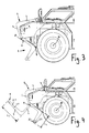
- Fig. 3 shows the ram protection element 1 in the ramming protection position shown above, the front contour of the vehicle periphery, so that in the event of a collision, the colliding with the vehicle obstacle first hits the Rammschutzelement 1.
- the ram protection element 1 is formed as a stable metal part, so that the lying in the direction behind the Rammtikelement 1 body parts are protected in the event of a collision against the obstacle, such as the winch 8, the headlight 9, etc.
- the pivoting takes place by folding down the Rammschutzelements 1 by slightly more than 180 ° in the direction of the road.
- the first leg 2 of the crash protection element 1, which is connected to the pivot axis A abuts against an inclined surface 4 of the vehicle which is inclined relative to the roadway.
- the Rammschutzelement 1 in the Rammschutz ein on the so-called.
- Lifting eyelets 7 of the vehicle which are arranged in the embodiment in the region in front of the windshield of the vehicle and used for air loading of the vehicle attached. Since these have a comparatively large distance relative to the first leg 2 of the crash protection element 1, the length of the second leg 3 is adjustable. While namely in the Rammtik ein the second leg 3 has a predetermined by the distance of the lifting lugs length L 1 , it is necessary in the support position to adapt the length of the second leg 3 by telescoping according to the soil conditions, see. the length L 2 in Fig. 4 ,
Landscapes
- Engineering & Computer Science (AREA)
- Mechanical Engineering (AREA)
- Body Structure For Vehicles (AREA)
- Superstructure Of Vehicle (AREA)
- Automatic Cycles, And Cycles In General (AREA)
Abstract
Description
- Die Erfindung betrifft ein Fahrzeug, insbesondere ein militärisches Fahrzeug, mit einem im Bereich der Fahrzeugfront angeordneten Rammschutzelement.
- Insbesondere bei geländegängigen Fahrzeugen ist es bekannt, diese im Bereich der Fahrzeugfront mit einem zum Schutz des Fahrzeugs im Falle von Kollisionen mit beispielsweise Wildtieren dienenden Rammschutzelement zu versehen. Bei bekannten Rammschutzelementen handelt es sich üblicherweise um starre Bügelelemente, die vor der eigentlichen Stoßstange des Fahrzeugs montiert werden, um die Fahrzeugfront im Falle eines Aufpralls vor Beschädigungen zu schützen.
- Darüber hinaus ist es ebenfalls vor allem von Geländefahrzeugen bekannt, diese im Bereich der Fahrzeugfront mit einer oftmals elektrisch betriebenen Seilwinde zu versehen. In diesem Zusammenhang hat es sich als nachteilig erwiesen, dass die Winde vorne im Bereich der Fahrzeugfront noch vor der Vorderachse des Fahrzeugs angeordnet ist, was in bestimmten Belastungssituationen zu einem instabilen Stand des Fahrzeugs führen kann.
- Aufgabe der Erfindung ist es, ein Fahrzeug der Eingangs genannten Art anzugeben, dessen Standeigenschaften bei Bedarf verbessert werden können.
- Diese Aufgabe wird bei einem Fahrzeug der eingangs genannten Art dadurch gelöst, dass das Rammschutzelement von einer Rammschutzstellung, in welcher das Rammschutzelement die Fahrzeugfront schützt, in eine Abstützstellung überführbar ist, in welcher das Rammschutzelement eine Abstützung gegenüber der Fahrbahn bildet.
- Durch Überführung des Rammschutzelements von der im Fahrbetrieb dem Fahrzeugschutz dienenden Rammschutzstellung in eine Abstützstellung ergeben sich günstigere Standeigenschaften des Fahrzeugs durch einen zusätzlichen, noch vor der Vorderachse liegenden Abstützpunkt. Insbesondere beim Betrieb einer elektrischen Winde verbessert die zusätzliche Abstützung den Stand des Fahrzeugs.
- Von konstruktivem Vorteil ist eine Ausgestaltung, nach welcher das Rammschutzelement durch Verschwenken um eine sich im Wesentlichen in horizontaler Richtung erstreckende Schwenkachse von der Rammschutzstellung in die Abstützstellung überführbar ist. Das Verschwenken kann von Hand durch manuelles Herunterklappen erfolgen.
- In weiterer Ausgestaltung wird vorgeschlagen, dass das Rammschutzelement zwei gegeneinander abgewinkelt verlaufende Schenkel aufweist. Die beiden Schenkel können in der Rammschutzstellung die Frontpartie des Fahrzeugs, beispielsweise dessen Motorhaube, nach Art eines Winkels umgreifen und auf diese Weise einen effektiven Rammschutz bereitstellen. In der Abstützstellung bilden die Schenkel Abstützarme, über welche sich das Fahrzeug über eine vor dessen Vorderachse liegenden Abstützpunkt gegenüber der Fahrbahn abstützt.
- Ferner ist konstruktiver Ausgestaltung vorgesehen, dass der erste Schenkel an seinem einen Ende an die Schwenkachse angebunden ist.
- Weiter wird vorgeschlagen, dass die Länge des zweiten Schenkels einstellbar ist. Durch Einstellen der Länge des zweiten, der Schwenkachse abgewandten Schenkels kann zum einen eine Arretierung in der Rammschutzstellung erfolgen. Zum anderen kann durch Einstellung der Schenkellänge und anschließende Arretierung eine den jeweiligen Bodengegebenheiten Rechnung tragende Abstützung in der Abstützstellung erfolgen.
- Weiterhin wird vorgeschlagen, dass eine geneigt gegenüber der Fahrbahn verlaufende Abstützfläche des Fahrzeugs vorgesehen ist, gegen welche der erste Schenkel des Rammschutzelements in der Abstützstellung anliegt. Auf diese Weise wird das Abstützelement in der Abstützstellung gehalten.
- In weiterer Ausgestaltung wird vorgeschlagen, dass der zweite Schenkel an seinem freien Ende ein eine flächige Auflage bereitstellendes Abstützelement aufweist.
- Weiter wird vorgeschlagen, dass das Rammschutzelement schwenkbeweglich an im Frontbereich des Fahrzeugs vorgesehenen Zurrösen befestigt ist. Derartige Zurrösen werden vor allem im militärischen Bereich weit verbreitet und in in ihren Abmaßen teilweise genormten Größen verwendet, weshalb die Anbindung des Rammschutzelements an die ohnehin vorgesehenen Zurrösen eine im Hinblick auf die Nachrüstung bereits im Betrieb befindlicher Fahrzeuge mit einem Rammschutzelement günstige Ausgestaltung bildet.
- Ebenso ist es von Vorteil, wenn das Rammschutzelement in der Rammschutzstellung an Hebeösen des Fahrzeugs oder an Flanschflächen der Hebeösen befestigt ist.
- Weitere Einzelheiten und Vorteile der Erfindung werden nachfolgend unter Zuhilfenahme der beigefügten Zeichnungen erläutert. Darin zeigen
- Fig. 1:
- eine perspektivische Ansicht auf den Frontbereich eines Fahr- zeugs mit einem Rammschutzelement,
- Fig. 2:
- eine weitere perspektivische Ansicht auf den Frontbereich eines Fahrzeugs mit einem Rammschutzelement, das sowohl in Rammschutzstellung wie auch in Abstützstellung darge- stellt ist,
- Fig. 3:
- eine der Darstellung in
Fig. 2 entsprechende seitliche Ansicht und - Fig. 4:
- eine der
Fig. 3 entsprechende Ansicht mit einer der Veran- schaulichung dienenden Zwischenstellung. -
Fig. 1 zeigt den Frontbereich eines geländegängigen Fahrzeugs, welcher über ein Rammschutzelement 1 vor Beschädigungen infolge von Kollisionen geschützt ist. Bei dem Fahrzeug handelt es sich um ein gepanzertes, militärisches Fahrzeug, welches mit einer elektrisch betriebenen Seilwinde 8 versehen ist. - Der Rammschutzbügel 1 ist in der Darstellung der
Fig. 1 in seiner Rammschutzstellung dargestellt, in welcher ein erster Schenkel 2 des Rammschutzelements 1 in im Wesentlichen vertikaler Richtung verläuft und der gegenüber dem ersten Schenkel 2 abgewinkelt verlaufende Schenkel 3 des Rammschutzelements 1 sich oberhalb der Motorhaube des militärischen Fahrzeugs in einer nahezu waagerechten Richtung erstreckt. - Das Rammschutzelement 1 ist insgesamt nach Art eines Winkels gestaltet, dessen Schenkel 2, 3 aus jeweils zwei Holmen 2.1, 2.2. und 3.1, 3.2 gebildet werden, die über Querverstrebungen 11, 12 miteinander verbunden sind, wobei der zweite Schenkel 3 zusätzlich ein mit zwei Einschubelementen 5.1, 5.2 versehenes Abstützelement 5 aufweist, über welches die Länge des zweiten Schenkels 3 einstellbar ist, vgl. auch
Fig. 2 . Die Einschubelemente 5.1, 5.2 sind nach Art von Teleskopschienen in die Holme 3.1, 3.2 einsteckbar, wodurch die Länge des zweiten Schenkels bei Bedarf einstellbar ist, was nachfolgend noch näher anhand der Darstellung inFig. 4 erörtert werden wird. - Weitere Elemente des Abstützelements 5 sind eine sich quer zur Fahrzeuglängsrichtung erstreckende Abstützstange 5.3 und ein die Abstützfläche vergrößerndes, sich parallel zur Abstützstange 5.3 erstreckendes Abstützblech 5.4.
- Das Rammschutzelement 1 ist schwenkbar um eine fahrzeugfesten Achse A gelagert, die durch an der Fahrzeugfront vorgesehene Zurrösen 6 hindurch verläuft. Aufgrund der Schwenklagerung an den Zurrösen 6 eignet sich das Rammschutzelement 1 auch zur Nachrüstung an bereits im Betrieb befindlichen Fahrzeugen, die ohne größere Umbaumaßnahmen nachträglich mit einem solchen Rammschutzelement 1 versehen werden können.
- Durch manuelles Schwenken um die Achse A lässt sich das Rammschutzelement 1 von der in
Fig. 1 dargestellten Rammschutzstellung in die inFig. 2 zusätzlich eingezeichnete Abstützstellung überführen, was nachfolgend anhand der Darstellungen inFig. 3 und Fig. 4 im Einzelnen erläutert werden wird. - Wie die Darstellung in
Fig. 3 zeigt, bildet das Rammschutzelement 1 in der oben dargestellten Rammschutzstellung die vordere Kontur der Fahrzeugperipherie, so dass im Falle einer Kollision das mit dem Fahrzeug kollidierende Hindernis zunächst auf das Rammschutzelement 1 trifft. Das Rammschutzelement 1 ist als stabiles Metallteil ausgebildet, so dass die in Fahrtrichtung hinter dem Rammschutzelement 1 liegenden Karosserieteile im Falle einer Kollision vor dem Hindernis geschützt werden, so beispielsweise die Winde 8, die Scheinwerfer 9 usw. - Im Falle eines Betriebs der Winde 8 ist es für die Standsicherheit des Fahrzeugs von Vorteil, wenn ein zusätzlicher Abstützpunkt im vorderen Bereich des Fahrzeugs, noch vor der Vorderachse 10 des Fahrzeugs, vorgesehen ist. Hierzu ist das Rammschutzelement 1 gemäß der Darstellung in
Fig. 3 von der oben eingezeichneten Rammschutzstellung in die weiter unten dargestellte Abstützstellung um die sich im Wesentlichen in horizontaler Richtung quer zum Fahrzeug erstreckende Achse A verschwenkbar. Die Verschwenkung erfolgt durch ein Herunterklappen des Rammschutzelements 1 um etwas mehr als 180° in Richtung der Fahrbahn. Nach einem gewissen Schwenkwinkel liegt der erste, an die Schwenkachse A angebundene Schenkel 2 des Rammschutzelements 1 an einer Schrägfläche 4 des Fahrzeugs, die gegenüber der Fahrbahn geneigt verläuft, an. Sobald das Fahrzeug unter dem Einfluss einer Last zu einer Kippbewegung um die Vorderachse 10 des Fahrzeugs neigt, erfolgt über den Rammschutzbügel 1 und die Fläche 4 eine zusätzliche, sich dieser Kippbewegung entgegen stellende Abstützung. - Wie die Darstellung insbesondere in
Fig. 4 erkennen lässt, ist das Rammschutzelement 1 in der Rammschutzstellung über die sog. Hebeösen 7 des Fahrzeugs, die beim Ausführungsbeispiel im Bereich vor der Frontscheibe des Fahrzeugs angeordnet und zur Luftverladung des Fahrzeugs dienen, befestigt. Da diese einen vergleichsweise großen Abstand gegenüber dem ersten Schenkel 2 des Rammschutzelements 1 aufweisen, ist die Länge des zweiten Schenkels 3 einstellbar. Während nämlich in der Rammschutzstellung der zweite Schenkel 3 eine durch den Abstand der Hebeösen vorgegebene Länge L1 aufweist, ist es in der Abstützstellung erforderlich, den die Länge des zweiten Schenkels 3 durch Teleskopieren entsprechend den Bodengegebenheiten anzupassen, vgl. die Länge L2 inFig. 4 . -
- 1
- Rammschutzelement
- 2
- Schenkel
- 2.1
- Holm
- 2.2
- Holm
- 3
- Schenkel
- 3.1
- Holm
- 3.2
- Holm
- 4
- Abstützfläche
- 5
- Abstützelement
- 5.1
- Einsteckelement
- 5.2
- Einsteckelement#
- 5.3
- Abstützstange
- 5.4
- Abstützblech
- 6
- Zurröse
- 7
- Hebeöse
- 8
- Winde
- 9
- Scheinwerfer
- 10
- Vorderachse
- 11
- Querverstrebung
- 12
- Querverstrebung
- A
- Achse
- L1
- Länge
- L2
- Länge
Claims (9)
- Fahrzeug, insbesondere militärisches Fahrzeug, mit einem im Bereich der Fahrzeugfront angeordneten Rammschutzelement (1),
dadurch gekennzeichnet,
dass das Rammschutzelement (1) von einer Rammschutzstellung, in welcher das Rammschutzelement (1) die Fahrzeugfront schützt, in eine Abstützstellung überführbar ist, in welcher das Rammschutzelement (1) eine Abstützung gegenüber der Fahrbahn bildet. - Fahrzeug nach Anspruch 1, dadurch gekennzeichnet, dass das Rammschutzelement (1) durch Verschwenken um eine sich im Wesentlichen in horizontaler Richtung erstreckende Schwenkachse (A) von der Rammschutzstellung in die Abstützstellung überführbar ist.
- Fahrzeug nach Anspruch 1 oder Anspruch 2, dadurch gekennzeichnet, dass das Rammschutzelement (1) zwei gegeneinander abgewinkelt verlaufende Schenkel (2, 3) aufweist.
- Fahrzeug nach Anspruch 3, dadurch gekennzeichnet, dass der erste Schenkel (2) an seinem einen Ende an die Schwenkachse (A) angebunden ist.
- Fahrzeug nach Anspruch 3 oder 4, dadurch gekennzeichnet, dass die Länge des zweiten Schenkels (3) einstellbar ist.
- Fahrzeug nach einem der vorhergehenden Ansprüche, gekennzeichnet durch eine geneigt gegenüber der Fahrbahn verlaufende Abstützfläche (4), gegen welche der erste Schenkel (2) des Rammschutzelements (1) in der Abstützstellung anliegt.
- Fahrzeug nach einem der vorhergehenden Ansprüche, dadurch gekennzeichnet, dass der zweite Schenkel (3) an seinem freien Ende ein Abstützelement (5) aufweist.
- Fahrzeug nach einem der vorhergehenden Ansprüche, dadurch gekennzeichnet, dass das Rammschutzelement (1) schwenkbeweglich an im Frontbereich des Fahrzeugs vorgesehenen Zurrösen (6) befestigt ist.
- Fahrzeug nach einem der vorhergehenden Ansprüche, dadurch gekennzeichnet, dass das Rammschutzelement (1) in der Rammschutzstellung an Hebeösen (7) des Fahrzeugs befestigt ist.
Applications Claiming Priority (1)
| Application Number | Priority Date | Filing Date | Title |
|---|---|---|---|
| DE102009031708A DE102009031708A1 (de) | 2009-07-04 | 2009-07-04 | Fahrzeug, insbesondere militärisches Fahrzeug |
Publications (3)
| Publication Number | Publication Date |
|---|---|
| EP2269876A2 true EP2269876A2 (de) | 2011-01-05 |
| EP2269876A3 EP2269876A3 (de) | 2011-03-02 |
| EP2269876B1 EP2269876B1 (de) | 2013-04-17 |
Family
ID=42752339
Family Applications (1)
| Application Number | Title | Priority Date | Filing Date |
|---|---|---|---|
| EP20100166617 Not-in-force EP2269876B1 (de) | 2009-07-04 | 2010-06-21 | Fahrzeug, insbesondere militärisches Fahrzeug, mit Rammschutz |
Country Status (3)
| Country | Link |
|---|---|
| EP (1) | EP2269876B1 (de) |
| DE (1) | DE102009031708A1 (de) |
| ES (1) | ES2415981T3 (de) |
Family Cites Families (5)
| Publication number | Priority date | Publication date | Assignee | Title |
|---|---|---|---|---|
| US1871331A (en) * | 1931-04-04 | 1932-08-09 | Int Motor Co | Bumper |
| DE2309554A1 (de) * | 1973-02-26 | 1974-09-05 | Kockums Ind Ab | Anordnung an fahrzeugen |
| GB2090204A (en) * | 1980-12-15 | 1982-07-07 | Metalair Ltd | Rear bumper assembly for tipping-body vehicles |
| JP2003054389A (ja) * | 2001-08-09 | 2003-02-26 | Kubota Corp | トラクタのリフト装置 |
| US20090074548A1 (en) * | 2004-11-26 | 2009-03-19 | Volvo Lastvagnar Ab | device for mounting on a vehicle comprising such a device |
-
2009
- 2009-07-04 DE DE102009031708A patent/DE102009031708A1/de not_active Withdrawn
-
2010
- 2010-06-21 ES ES10166617T patent/ES2415981T3/es active Active
- 2010-06-21 EP EP20100166617 patent/EP2269876B1/de not_active Not-in-force
Non-Patent Citations (1)
| Title |
|---|
| None |
Also Published As
| Publication number | Publication date |
|---|---|
| DE102009031708A1 (de) | 2011-01-05 |
| ES2415981T3 (es) | 2013-07-29 |
| EP2269876B1 (de) | 2013-04-17 |
| EP2269876A3 (de) | 2011-03-02 |
Similar Documents
| Publication | Publication Date | Title |
|---|---|---|
| EP1520939A2 (de) | Ladegerät | |
| DE102011055350B4 (de) | Unterfahrschutz zur Anbringung am Heck eines Lastkraftwagens | |
| EP3172091A1 (de) | Fahrzeug mit einer fussgängerschutzvorrichtung | |
| DE202018101373U1 (de) | Heckaufprallschutz für ein Fahrzeug | |
| DE102016010353A1 (de) | Schutzeinrichtung für eine Personenkraftwagenkarosserie | |
| DE69105201T2 (de) | Fahrzeuganhängerkupplung. | |
| EP2042410B1 (de) | Landwirtschaftliches Fahrzeug | |
| EP3459900B1 (de) | Fahrzeugstütze mit klappteil | |
| DE102013015615B4 (de) | Frontstruktur für ein Kraftfahrzeug | |
| DE202011101120U1 (de) | Stützrad für Fahrzeuganhänger | |
| EP2269876B1 (de) | Fahrzeug, insbesondere militärisches Fahrzeug, mit Rammschutz | |
| DE102015113283A1 (de) | Baukasten zum Erstellen verschiedener Wechselrahmen für Nutzfahrzeuge sowie daraus hergestellter Wechselrahmen | |
| EP3650615B1 (de) | Autobetonpumpe | |
| DE102004064293A1 (de) | Klappbare Unterfahrschutzeinrichtung | |
| EP2219904B1 (de) | Unterfahrschutzeinrichtung für einen lastkraftwagen | |
| EP3663173B1 (de) | Vorrichtung zum lagern eines hinteren bereichs eines fahrerhauses eines nutzfahrzeugs | |
| DE102013101966A1 (de) | Anordnung zum hydraulischen Stabilisieren eines Klappelements | |
| EP3560883B1 (de) | Fahrzeug | |
| EP4046866A1 (de) | Ladebordwandsystem mit beweglichem unterfahrschutz | |
| EP3909814A1 (de) | Unterfahrschutz für ein nutzfahrzeug | |
| DE102007035655B4 (de) | Abstützvorrichtung für Außenbordmotor | |
| DE102015008083A1 (de) | Abschleppvorrichtung | |
| DE102023103079B3 (de) | Innenlader mit variablem Unterfahrschutz | |
| EP3495174A1 (de) | Höhenverstellbare zugdeichsel | |
| DE202019101978U1 (de) | Trageinrichtung |
Legal Events
| Date | Code | Title | Description |
|---|---|---|---|
| PUAI | Public reference made under article 153(3) epc to a published international application that has entered the european phase |
Free format text: ORIGINAL CODE: 0009012 |
|
| AK | Designated contracting states |
Kind code of ref document: A2 Designated state(s): AL AT BE BG CH CY CZ DE DK EE ES FI FR GB GR HR HU IE IS IT LI LT LU LV MC MK MT NL NO PL PT RO SE SI SK SM TR |
|
| AX | Request for extension of the european patent |
Extension state: BA ME RS |
|
| PUAL | Search report despatched |
Free format text: ORIGINAL CODE: 0009013 |
|
| AK | Designated contracting states |
Kind code of ref document: A3 Designated state(s): AL AT BE BG CH CY CZ DE DK EE ES FI FR GB GR HR HU IE IS IT LI LT LU LV MC MK MT NL NO PL PT RO SE SI SK SM TR |
|
| AX | Request for extension of the european patent |
Extension state: BA ME RS |
|
| 17P | Request for examination filed |
Effective date: 20110902 |
|
| 17Q | First examination report despatched |
Effective date: 20111229 |
|
| GRAP | Despatch of communication of intention to grant a patent |
Free format text: ORIGINAL CODE: EPIDOSNIGR1 |
|
| GRAS | Grant fee paid |
Free format text: ORIGINAL CODE: EPIDOSNIGR3 |
|
| GRAA | (expected) grant |
Free format text: ORIGINAL CODE: 0009210 |
|
| RIN1 | Information on inventor provided before grant (corrected) |
Inventor name: DIELING, FRANK Inventor name: SCHEIBEL, AXEL DR. Inventor name: PRUMMENBAUM, ERIC |
|
| AK | Designated contracting states |
Kind code of ref document: B1 Designated state(s): AL AT BE BG CH CY CZ DE DK EE ES FI FR GB GR HR HU IE IS IT LI LT LU LV MC MK MT NL NO PL PT RO SE SI SK SM TR |
|
| REG | Reference to a national code |
Ref country code: GB Ref legal event code: FG4D Free format text: NOT ENGLISH |
|
| REG | Reference to a national code |
Ref country code: CH Ref legal event code: EP |
|
| REG | Reference to a national code |
Ref country code: IE Ref legal event code: FG4D Free format text: LANGUAGE OF EP DOCUMENT: GERMAN |
|
| REG | Reference to a national code |
Ref country code: AT Ref legal event code: REF Ref document number: 607060 Country of ref document: AT Kind code of ref document: T Effective date: 20130515 Ref country code: CH Ref legal event code: NV Representative=s name: BOHEST AG, CH |
|
| REG | Reference to a national code |
Ref country code: DE Ref legal event code: R096 Ref document number: 502010002936 Country of ref document: DE Effective date: 20130613 |
|
| REG | Reference to a national code |
Ref country code: ES Ref legal event code: FG2A Ref document number: 2415981 Country of ref document: ES Kind code of ref document: T3 Effective date: 20130729 |
|
| REG | Reference to a national code |
Ref country code: NL Ref legal event code: T3 |
|
| REG | Reference to a national code |
Ref country code: LT Ref legal event code: MG4D |
|
| PG25 | Lapsed in a contracting state [announced via postgrant information from national office to epo] |
Ref country code: NO Free format text: LAPSE BECAUSE OF FAILURE TO SUBMIT A TRANSLATION OF THE DESCRIPTION OR TO PAY THE FEE WITHIN THE PRESCRIBED TIME-LIMIT Effective date: 20130717 Ref country code: SE Free format text: LAPSE BECAUSE OF FAILURE TO SUBMIT A TRANSLATION OF THE DESCRIPTION OR TO PAY THE FEE WITHIN THE PRESCRIBED TIME-LIMIT Effective date: 20130417 Ref country code: FI Free format text: LAPSE BECAUSE OF FAILURE TO SUBMIT A TRANSLATION OF THE DESCRIPTION OR TO PAY THE FEE WITHIN THE PRESCRIBED TIME-LIMIT Effective date: 20130417 Ref country code: GR Free format text: LAPSE BECAUSE OF FAILURE TO SUBMIT A TRANSLATION OF THE DESCRIPTION OR TO PAY THE FEE WITHIN THE PRESCRIBED TIME-LIMIT Effective date: 20130718 Ref country code: IS Free format text: LAPSE BECAUSE OF FAILURE TO SUBMIT A TRANSLATION OF THE DESCRIPTION OR TO PAY THE FEE WITHIN THE PRESCRIBED TIME-LIMIT Effective date: 20130817 Ref country code: SI Free format text: LAPSE BECAUSE OF FAILURE TO SUBMIT A TRANSLATION OF THE DESCRIPTION OR TO PAY THE FEE WITHIN THE PRESCRIBED TIME-LIMIT Effective date: 20130417 Ref country code: PT Free format text: LAPSE BECAUSE OF FAILURE TO SUBMIT A TRANSLATION OF THE DESCRIPTION OR TO PAY THE FEE WITHIN THE PRESCRIBED TIME-LIMIT Effective date: 20130819 Ref country code: LT Free format text: LAPSE BECAUSE OF FAILURE TO SUBMIT A TRANSLATION OF THE DESCRIPTION OR TO PAY THE FEE WITHIN THE PRESCRIBED TIME-LIMIT Effective date: 20130417 |
|
| PG25 | Lapsed in a contracting state [announced via postgrant information from national office to epo] |
Ref country code: CY Free format text: LAPSE BECAUSE OF FAILURE TO SUBMIT A TRANSLATION OF THE DESCRIPTION OR TO PAY THE FEE WITHIN THE PRESCRIBED TIME-LIMIT Effective date: 20130417 Ref country code: HR Free format text: LAPSE BECAUSE OF FAILURE TO SUBMIT A TRANSLATION OF THE DESCRIPTION OR TO PAY THE FEE WITHIN THE PRESCRIBED TIME-LIMIT Effective date: 20130417 Ref country code: LV Free format text: LAPSE BECAUSE OF FAILURE TO SUBMIT A TRANSLATION OF THE DESCRIPTION OR TO PAY THE FEE WITHIN THE PRESCRIBED TIME-LIMIT Effective date: 20130417 Ref country code: PL Free format text: LAPSE BECAUSE OF FAILURE TO SUBMIT A TRANSLATION OF THE DESCRIPTION OR TO PAY THE FEE WITHIN THE PRESCRIBED TIME-LIMIT Effective date: 20130417 Ref country code: BG Free format text: LAPSE BECAUSE OF FAILURE TO SUBMIT A TRANSLATION OF THE DESCRIPTION OR TO PAY THE FEE WITHIN THE PRESCRIBED TIME-LIMIT Effective date: 20130717 |
|
| BERE | Be: lapsed |
Owner name: KRAUSS-MAFFEI WEGMANN G.M.B.H. & CO. KG Effective date: 20130630 |
|
| PG25 | Lapsed in a contracting state [announced via postgrant information from national office to epo] |
Ref country code: DK Free format text: LAPSE BECAUSE OF FAILURE TO SUBMIT A TRANSLATION OF THE DESCRIPTION OR TO PAY THE FEE WITHIN THE PRESCRIBED TIME-LIMIT Effective date: 20130417 Ref country code: CZ Free format text: LAPSE BECAUSE OF FAILURE TO SUBMIT A TRANSLATION OF THE DESCRIPTION OR TO PAY THE FEE WITHIN THE PRESCRIBED TIME-LIMIT Effective date: 20130417 Ref country code: MC Free format text: LAPSE BECAUSE OF FAILURE TO SUBMIT A TRANSLATION OF THE DESCRIPTION OR TO PAY THE FEE WITHIN THE PRESCRIBED TIME-LIMIT Effective date: 20130417 Ref country code: EE Free format text: LAPSE BECAUSE OF FAILURE TO SUBMIT A TRANSLATION OF THE DESCRIPTION OR TO PAY THE FEE WITHIN THE PRESCRIBED TIME-LIMIT Effective date: 20130417 Ref country code: SK Free format text: LAPSE BECAUSE OF FAILURE TO SUBMIT A TRANSLATION OF THE DESCRIPTION OR TO PAY THE FEE WITHIN THE PRESCRIBED TIME-LIMIT Effective date: 20130417 |
|
| PLBE | No opposition filed within time limit |
Free format text: ORIGINAL CODE: 0009261 |
|
| STAA | Information on the status of an ep patent application or granted ep patent |
Free format text: STATUS: NO OPPOSITION FILED WITHIN TIME LIMIT |
|
| PG25 | Lapsed in a contracting state [announced via postgrant information from national office to epo] |
Ref country code: RO Free format text: LAPSE BECAUSE OF FAILURE TO SUBMIT A TRANSLATION OF THE DESCRIPTION OR TO PAY THE FEE WITHIN THE PRESCRIBED TIME-LIMIT Effective date: 20130417 |
|
| 26N | No opposition filed |
Effective date: 20140120 |
|
| REG | Reference to a national code |
Ref country code: IE Ref legal event code: MM4A |
|
| PG25 | Lapsed in a contracting state [announced via postgrant information from national office to epo] |
Ref country code: BE Free format text: LAPSE BECAUSE OF NON-PAYMENT OF DUE FEES Effective date: 20130630 |
|
| PG25 | Lapsed in a contracting state [announced via postgrant information from national office to epo] |
Ref country code: IE Free format text: LAPSE BECAUSE OF NON-PAYMENT OF DUE FEES Effective date: 20130621 |
|
| REG | Reference to a national code |
Ref country code: DE Ref legal event code: R097 Ref document number: 502010002936 Country of ref document: DE Effective date: 20140120 |
|
| REG | Reference to a national code |
Ref country code: CH Ref legal event code: PCAR Free format text: NEW ADDRESS: HOLBEINSTRASSE 36-38, 4051 BASEL (CH) |
|
| PG25 | Lapsed in a contracting state [announced via postgrant information from national office to epo] |
Ref country code: MT Free format text: LAPSE BECAUSE OF FAILURE TO SUBMIT A TRANSLATION OF THE DESCRIPTION OR TO PAY THE FEE WITHIN THE PRESCRIBED TIME-LIMIT Effective date: 20130417 |
|
| PG25 | Lapsed in a contracting state [announced via postgrant information from national office to epo] |
Ref country code: SM Free format text: LAPSE BECAUSE OF FAILURE TO SUBMIT A TRANSLATION OF THE DESCRIPTION OR TO PAY THE FEE WITHIN THE PRESCRIBED TIME-LIMIT Effective date: 20130417 |
|
| PG25 | Lapsed in a contracting state [announced via postgrant information from national office to epo] |
Ref country code: TR Free format text: LAPSE BECAUSE OF FAILURE TO SUBMIT A TRANSLATION OF THE DESCRIPTION OR TO PAY THE FEE WITHIN THE PRESCRIBED TIME-LIMIT Effective date: 20130417 |
|
| PG25 | Lapsed in a contracting state [announced via postgrant information from national office to epo] |
Ref country code: LU Free format text: LAPSE BECAUSE OF NON-PAYMENT OF DUE FEES Effective date: 20130621 Ref country code: HU Free format text: LAPSE BECAUSE OF FAILURE TO SUBMIT A TRANSLATION OF THE DESCRIPTION OR TO PAY THE FEE WITHIN THE PRESCRIBED TIME-LIMIT; INVALID AB INITIO Effective date: 20100621 Ref country code: MK Free format text: LAPSE BECAUSE OF FAILURE TO SUBMIT A TRANSLATION OF THE DESCRIPTION OR TO PAY THE FEE WITHIN THE PRESCRIBED TIME-LIMIT Effective date: 20130417 |
|
| REG | Reference to a national code |
Ref country code: FR Ref legal event code: PLFP Year of fee payment: 7 |
|
| REG | Reference to a national code |
Ref country code: FR Ref legal event code: PLFP Year of fee payment: 8 |
|
| REG | Reference to a national code |
Ref country code: FR Ref legal event code: PLFP Year of fee payment: 9 |
|
| PGFP | Annual fee paid to national office [announced via postgrant information from national office to epo] |
Ref country code: DE Payment date: 20180630 Year of fee payment: 9 Ref country code: NL Payment date: 20180625 Year of fee payment: 9 Ref country code: CH Payment date: 20180626 Year of fee payment: 9 |
|
| PGFP | Annual fee paid to national office [announced via postgrant information from national office to epo] |
Ref country code: FR Payment date: 20180625 Year of fee payment: 9 Ref country code: AT Payment date: 20180620 Year of fee payment: 9 |
|
| PG25 | Lapsed in a contracting state [announced via postgrant information from national office to epo] |
Ref country code: AL Free format text: LAPSE BECAUSE OF FAILURE TO SUBMIT A TRANSLATION OF THE DESCRIPTION OR TO PAY THE FEE WITHIN THE PRESCRIBED TIME-LIMIT Effective date: 20130417 |
|
| PGFP | Annual fee paid to national office [announced via postgrant information from national office to epo] |
Ref country code: GB Payment date: 20180626 Year of fee payment: 9 Ref country code: ES Payment date: 20180723 Year of fee payment: 9 Ref country code: IT Payment date: 20180622 Year of fee payment: 9 |
|
| REG | Reference to a national code |
Ref country code: DE Ref legal event code: R119 Ref document number: 502010002936 Country of ref document: DE |
|
| REG | Reference to a national code |
Ref country code: CH Ref legal event code: PL |
|
| REG | Reference to a national code |
Ref country code: NL Ref legal event code: MM Effective date: 20190701 |
|
| REG | Reference to a national code |
Ref country code: AT Ref legal event code: MM01 Ref document number: 607060 Country of ref document: AT Kind code of ref document: T Effective date: 20190621 |
|
| GBPC | Gb: european patent ceased through non-payment of renewal fee |
Effective date: 20190621 |
|
| PG25 | Lapsed in a contracting state [announced via postgrant information from national office to epo] |
Ref country code: DE Free format text: LAPSE BECAUSE OF NON-PAYMENT OF DUE FEES Effective date: 20200101 Ref country code: AT Free format text: LAPSE BECAUSE OF NON-PAYMENT OF DUE FEES Effective date: 20190621 Ref country code: IT Free format text: LAPSE BECAUSE OF NON-PAYMENT OF DUE FEES Effective date: 20190621 Ref country code: GB Free format text: LAPSE BECAUSE OF NON-PAYMENT OF DUE FEES Effective date: 20190621 Ref country code: NL Free format text: LAPSE BECAUSE OF NON-PAYMENT OF DUE FEES Effective date: 20190701 |
|
| PG25 | Lapsed in a contracting state [announced via postgrant information from national office to epo] |
Ref country code: CH Free format text: LAPSE BECAUSE OF NON-PAYMENT OF DUE FEES Effective date: 20190630 Ref country code: LI Free format text: LAPSE BECAUSE OF NON-PAYMENT OF DUE FEES Effective date: 20190630 |
|
| PG25 | Lapsed in a contracting state [announced via postgrant information from national office to epo] |
Ref country code: FR Free format text: LAPSE BECAUSE OF NON-PAYMENT OF DUE FEES Effective date: 20190630 |
|
| REG | Reference to a national code |
Ref country code: ES Ref legal event code: FD2A Effective date: 20201029 |
|
| PG25 | Lapsed in a contracting state [announced via postgrant information from national office to epo] |
Ref country code: ES Free format text: LAPSE BECAUSE OF NON-PAYMENT OF DUE FEES Effective date: 20190622 |