EP2269481A2 - Haareisen - Google Patents
Haareisen Download PDFInfo
- Publication number
- EP2269481A2 EP2269481A2 EP10166158A EP10166158A EP2269481A2 EP 2269481 A2 EP2269481 A2 EP 2269481A2 EP 10166158 A EP10166158 A EP 10166158A EP 10166158 A EP10166158 A EP 10166158A EP 2269481 A2 EP2269481 A2 EP 2269481A2
- Authority
- EP
- European Patent Office
- Prior art keywords
- hair
- potential
- clip portion
- ions
- hair clip
- Prior art date
- Legal status (The legal status is an assumption and is not a legal conclusion. Google has not performed a legal analysis and makes no representation as to the accuracy of the status listed.)
- Withdrawn
Links
- XEEYBQQBJWHFJM-UHFFFAOYSA-N Iron Chemical compound [Fe] XEEYBQQBJWHFJM-UHFFFAOYSA-N 0.000 title claims abstract description 88
- 229910052742 iron Inorganic materials 0.000 title claims abstract description 44
- 150000002500 ions Chemical class 0.000 claims abstract description 146
- 239000004020 conductor Substances 0.000 claims description 6
- 230000008878 coupling Effects 0.000 claims 1
- 238000010168 coupling process Methods 0.000 claims 1
- 238000005859 coupling reaction Methods 0.000 claims 1
- 229910001111 Fine metal Inorganic materials 0.000 description 29
- 239000002923 metal particle Substances 0.000 description 29
- 239000003595 mist Substances 0.000 description 18
- 238000003825 pressing Methods 0.000 description 16
- 229910052751 metal Inorganic materials 0.000 description 9
- 239000002184 metal Substances 0.000 description 9
- BASFCYQUMIYNBI-UHFFFAOYSA-N platinum Chemical compound [Pt] BASFCYQUMIYNBI-UHFFFAOYSA-N 0.000 description 6
- XLYOFNOQVPJJNP-UHFFFAOYSA-N water Substances O XLYOFNOQVPJJNP-UHFFFAOYSA-N 0.000 description 6
- 238000001816 cooling Methods 0.000 description 4
- RYGMFSIKBFXOCR-UHFFFAOYSA-N Copper Chemical compound [Cu] RYGMFSIKBFXOCR-UHFFFAOYSA-N 0.000 description 3
- HCHKCACWOHOZIP-UHFFFAOYSA-N Zinc Chemical compound [Zn] HCHKCACWOHOZIP-UHFFFAOYSA-N 0.000 description 3
- 239000003963 antioxidant agent Substances 0.000 description 3
- 230000003078 antioxidant effect Effects 0.000 description 3
- 229910052802 copper Inorganic materials 0.000 description 3
- 239000010949 copper Substances 0.000 description 3
- 238000010438 heat treatment Methods 0.000 description 3
- WABPQHHGFIMREM-UHFFFAOYSA-N lead(0) Chemical compound [Pb] WABPQHHGFIMREM-UHFFFAOYSA-N 0.000 description 3
- 229910052697 platinum Inorganic materials 0.000 description 3
- 230000008961 swelling Effects 0.000 description 3
- 229910052723 transition metal Inorganic materials 0.000 description 3
- 150000003624 transition metals Chemical class 0.000 description 3
- 229910052725 zinc Inorganic materials 0.000 description 3
- 239000011701 zinc Substances 0.000 description 3
- KDLHZDBZIXYQEI-UHFFFAOYSA-N Palladium Chemical compound [Pd] KDLHZDBZIXYQEI-UHFFFAOYSA-N 0.000 description 2
- BQCADISMDOOEFD-UHFFFAOYSA-N Silver Chemical compound [Ag] BQCADISMDOOEFD-UHFFFAOYSA-N 0.000 description 2
- RTAQQCXQSZGOHL-UHFFFAOYSA-N Titanium Chemical compound [Ti] RTAQQCXQSZGOHL-UHFFFAOYSA-N 0.000 description 2
- 230000000844 anti-bacterial effect Effects 0.000 description 2
- 239000003990 capacitor Substances 0.000 description 2
- 239000000470 constituent Substances 0.000 description 2
- 239000010419 fine particle Substances 0.000 description 2
- PCHJSUWPFVWCPO-UHFFFAOYSA-N gold Chemical compound [Au] PCHJSUWPFVWCPO-UHFFFAOYSA-N 0.000 description 2
- 229910052737 gold Inorganic materials 0.000 description 2
- 239000010931 gold Substances 0.000 description 2
- 239000000463 material Substances 0.000 description 2
- 229910052709 silver Inorganic materials 0.000 description 2
- 239000004332 silver Substances 0.000 description 2
- 229920003002 synthetic resin Polymers 0.000 description 2
- 239000000057 synthetic resin Substances 0.000 description 2
- 229910052719 titanium Inorganic materials 0.000 description 2
- 239000010936 titanium Substances 0.000 description 2
- -1 NO2 - Chemical class 0.000 description 1
- KJTLSVCANCCWHF-UHFFFAOYSA-N Ruthenium Chemical compound [Ru] KJTLSVCANCCWHF-UHFFFAOYSA-N 0.000 description 1
- 229910045601 alloy Inorganic materials 0.000 description 1
- 239000000956 alloy Substances 0.000 description 1
- 238000000889 atomisation Methods 0.000 description 1
- 230000010485 coping Effects 0.000 description 1
- 230000000694 effects Effects 0.000 description 1
- 239000000945 filler Substances 0.000 description 1
- 230000020169 heat generation Effects 0.000 description 1
- 239000008236 heating water Substances 0.000 description 1
- 229910052741 iridium Inorganic materials 0.000 description 1
- GKOZUEZYRPOHIO-UHFFFAOYSA-N iridium atom Chemical compound [Ir] GKOZUEZYRPOHIO-UHFFFAOYSA-N 0.000 description 1
- 235000000396 iron Nutrition 0.000 description 1
- 239000007769 metal material Substances 0.000 description 1
- 238000000034 method Methods 0.000 description 1
- 229910052762 osmium Inorganic materials 0.000 description 1
- SYQBFIAQOQZEGI-UHFFFAOYSA-N osmium atom Chemical compound [Os] SYQBFIAQOQZEGI-UHFFFAOYSA-N 0.000 description 1
- 229910052763 palladium Inorganic materials 0.000 description 1
- 230000002093 peripheral effect Effects 0.000 description 1
- 238000007747 plating Methods 0.000 description 1
- 229910052703 rhodium Inorganic materials 0.000 description 1
- 239000010948 rhodium Substances 0.000 description 1
- MHOVAHRLVXNVSD-UHFFFAOYSA-N rhodium atom Chemical compound [Rh] MHOVAHRLVXNVSD-UHFFFAOYSA-N 0.000 description 1
- 229910052707 ruthenium Inorganic materials 0.000 description 1
- 229920006395 saturated elastomer Polymers 0.000 description 1
- 229910001220 stainless steel Inorganic materials 0.000 description 1
- 239000010935 stainless steel Substances 0.000 description 1
- 239000000126 substance Substances 0.000 description 1
- WFKWXMTUELFFGS-UHFFFAOYSA-N tungsten Chemical compound [W] WFKWXMTUELFFGS-UHFFFAOYSA-N 0.000 description 1
- 229910052721 tungsten Inorganic materials 0.000 description 1
- 239000010937 tungsten Substances 0.000 description 1
Images


Classifications
-
- A—HUMAN NECESSITIES
- A45—HAND OR TRAVELLING ARTICLES
- A45D—HAIRDRESSING OR SHAVING EQUIPMENT; EQUIPMENT FOR COSMETICS OR COSMETIC TREATMENTS, e.g. FOR MANICURING OR PEDICURING
- A45D1/00—Curling-tongs, i.e. tongs for use when hot; Curling-irons, i.e. irons for use when hot; Accessories therefor
- A45D1/06—Curling-tongs, i.e. tongs for use when hot; Curling-irons, i.e. irons for use when hot; Accessories therefor with two or more jaws
-
- A—HUMAN NECESSITIES
- A45—HAND OR TRAVELLING ARTICLES
- A45D—HAIRDRESSING OR SHAVING EQUIPMENT; EQUIPMENT FOR COSMETICS OR COSMETIC TREATMENTS, e.g. FOR MANICURING OR PEDICURING
- A45D2/00—Hair-curling or hair-waving appliances ; Appliances for hair dressing treatment not otherwise provided for
- A45D2/001—Hair straightening appliances
-
- A—HUMAN NECESSITIES
- A45—HAND OR TRAVELLING ARTICLES
- A45D—HAIRDRESSING OR SHAVING EQUIPMENT; EQUIPMENT FOR COSMETICS OR COSMETIC TREATMENTS, e.g. FOR MANICURING OR PEDICURING
- A45D2200/00—Details not otherwise provided for in A45D
- A45D2200/20—Additional enhancing means
- A45D2200/202—Ionisation
Definitions
- the present invention relates to a hair iron.
- a hair iron as a type of hair care apparatuses includes: a clip portion that clips hair; and a heating unit that is provided in the clip portion and heats the hair thus clipped, and is configured to be capable of giving desired styling such as curling and straightening the hair clipped in the clip portion.
- Patent Literature 1 As disclosed in Japanese Patent Laid-Open Publication No. 2003-059622 (hereinafter, referred to as Patent Literature 1), as the hair care apparatus as described above, one is known, which has an ion generation portion provided therein and is configured to be capable of adhering, onto an object such as hair, ions generated by the ion generation portion, and in addition, has potential holding means provided therein, the potential holding means being for holding a potential of the object concerned at a predetermined potential, and is configured to be capable of continuously adhering the ions onto the object.
- Patent Literature 1 Japanese Patent Laid-Open Publication No. 2003-059622
- Patent Literature 1 described above, though the potential holding means for holding the potential of the object so as to continuously adhere the ions onto the object (hair) is provided, any coping method with electrostatic charge of a member existing on a periphery of the object is not mentioned at all. Therefore, in the case where a hair iron is used as the hair care apparatus, at the time when the member existing on the periphery of the object, for example, a hair clip portion is electrically charged at the same polarity as that of the ions thus emitted, the electrostatic charge of the hair clip portion has not been able to be removed effectively. Therefore, it has been apprehended that the ions emitted from the ion generation portion may repel electric charges of the same polarity, which are charged to such a peripheral member of the object, resulting in insufficient distribution of the ions to the object.
- a hair iron which includes: a grip portion; a hair clip portion that is provided continuously with one end of the grip portion and clips hair; and an ion generation portion that generate ions, wherein a potential holding unit that holds a potential of the hair clip portion is connected to the hair clip portion.
- the potential holding unit is provided in the hair clip portion, whereby the hair clip portion can be held at a potential that facilitates the ions emitted from the ion generation portion to be adhered onto the hair with respect to electric charges of the ions. Accordingly, it becomes possible to efficiently adhere the ions onto the hair.
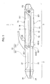
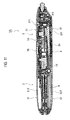
- a case is illustrated, where the present invention is applied to a hair iron 1 capable of giving straight styling to hair and capable of giving curl styling to the hair.
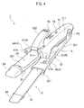
- the hair iron 1 includes: a hair clip portion 2 that gives the styling to the hair by clipping the hair; and a grip portion that holds the hair clip portion 2 by being gripped by a user. Then, in the hair iron 1 according to this embodiment, ion generation portions 4 (refer to FIG. 4 ) are provided, which generate ions, and in addition, emit the generated ions toward a bundle of the hair clipped into the hair clip portion 2.
- the hair clip portion 2 is composed of: a pair of semicylindrical split clip portions 21 and 22, which has opposed and outer circumferential surfaces serving as heating surfaces, and clip the hair by freely approaching and departing from each other; and a pressing plate 23 that clips the hair by freely approaching and departing from the outer circumferential surface of the split clip portion 21 as one (upside in FIG. 1 ) of these split clip portions 21 and 22.
- the split clip portions 21 and 22 are individually formed of metal (for example, copper) into a semicircular shape in cross section.
- the metal is a conductive material having high thermal conductivity.
- heaters 6 (refer to FIG. 5 ) which heat the opposed and outer circumferential surfaces of these split clip portions 21 and 22 are built.
- the bundle of the hair is clipped between the opposed surfaces of the pair of split clip portions 21 and 22, whereby the hair thus clipped is heated and warmed by the opposed surfaces, and it becomes possible to give the straight styling to the hair.
- water tanks 24 are provided, and water reserved in the water tanks 24 is supplied to the heaters 6 and is evaporated thereby, whereby the water can be jetted as steam outward from the circumferential surfaces of the split clip portions 21 and 22.
- the pressing plate 23 is formed into a circular arc shape in cross section, which goes along the outer circumferential surface of the split clip portion 21, and is then pivotally attached thereto so as to be capable of moving rotationally about a pivot point P1 taken as an axis.
- the pressing plate 23 includes: a pressing surface portion 231 extending in a spatula shape in the tip end direction; and an operation portion 232 extended from a base end portion of the pressing surface portion 231 in a direction of the grip portion 3. Then, as shown in FIG. 1 , a tip end side of the extended operation portion 232 is lifted obliquely upward so as to depart from the grip portion 3, and a base portion thereof is attached to the tip end portion of the grip portion 3 while interposing a spring 25 therebetween.
- the pressing surface portion 231 thereof is brought into elastic contact with the outer circumferential surface of the split clip portion 21 by urging force of the spring 25.
- the operation portion 232 is operated against the urging force of the spring 25 in a direction of pressing the operation portion 232 concerned in a direction of the split clip portion 21, whereby the pressing surface portion 231 is opened and departs from the split clip portion 21 about the pivot point P1 taken as a center.
- the bundle of the hair is inserted between the pressing surface portion 231 and the split clip portion 21, and the pressing force for the operation portion 232 is thereafter released.
- the hair can be clipped between the pressing surface portion 231 and the outer circumferential surface of the split clip portion 21.
- the hair clipped between the pressing surface portion 231 and the split clip portion 21 is heated and warmed from the outer circumferential surface of the split clip portion 21 that has become the heating surface, and curl styling can be given to the hair.
- the grip portion 3 is composed of split grip portions 31 and 32 split so as to continue with the respective split clip portions 21 and 22, in which the split clip portion 21 as one of the pair is integrally protruded from a tip end of the split grip portion 31 as one of the pair, and the other split clip portion 22 is integrally protruded from a tip end of the other split grip portion 32.
- holding members 211 and 221 are coupled to base portions of the respective split clip portions 21 and 22. Then, the holding member 211 of the split clip portion 21 as one of the pair is detachably attached by a screw (not shown) to a tip end portion of the split grip portion 31 as one of the pair, and in detail, to a tip end portion of a housing 311 to be described later, and in a similar way, the holding member 221 of the other split clip portion 22 is detachably attached by a screw (not shown) to a tip end portion of the other split grip portion 32, and in detail, to a tip end portion of a housing 321 to be described later.
- the hair clip portion 2 can be detached from the grip portion 3 by detaching the screws, and it is made possible to replace the hair clip portion 2.
- the split grip portion 31 and the split clip portion 21, which are integrated with each other, and the split grip portion 32 and the split clip portion 22, which are integrated with each other, are configured to be capable of mutually opening and closing (approaching and departing from each other).
- a base portion of the split grip portion 31 and a base portion of the split grip portion 32 are pivotally attached to each other while interposing a spring (not shown) therebetween so as to be capable of moving rotationally about a pivot point P2 taken as an axis.
- the spring is urged in a direction of opening the split grip portions 31 and 32 by predetermined amounts, and both of the split grip portions 31 and 32 are tightly gripped, whereby the split body portions 21 and 22 are closed, whereby the hair can be clipped therebetween.
- the respective split grip portions 31 and 32 are covered with synthetic resin-made housings 311 and 321 which form contours thereof, and as shown in FIG. 5 , lead wires which connect to the respective heaters 6 are housed in insides of the housings 311 and 321.
- a power supply switch 7A and a temperature switching switch 7B are provided on the housing 311 as one of the pair, and a lock switch 7C and a conductive member 51 of an electric charge unit 5 are provided on the other housing 321.
- the power supply switch 7A is a switch that turns on/off energization to all of electrical components, that is, the heaters 6, the ion generation portions 4, the electric charge unit 5, and further, potential holding means 10 to be described later, and the like.
- the temperature switching switch 7B is a switch that switches heat generation amounts of the heaters 6, and the lock switch 7C is a switch that locks a closed state of the split clip portions 21 and 22 and releasing such locking. Note that, though not shown, a power supply cord is connected to a terminal end portion (right end portion in FIG. 1 ) of the grip portion 3.
- the two ion generation portions 4 which generate the ions are provided in swelling portions 312A and 312B formed by swelling, to both sides, the tip end portion of the housing 311 that covers the split grip portion 31 as one of the pair. Then, one of the two ion generation portions 4 is formed as a mist generation portion 4A that generates mist, and the other thereof is formed as a fine metal particle generation portion 4B that generates fine metal particles. Then, the ions (mist and fine metal particles) generated in the mist generation portion 4A and the fine metal particle generation portion 4B are emitted from emission ports 41A and 41B, respectively.
- mist generation portion 4A a device is used, which, by taking a ground electrode as a reference, applies a high voltage from a high voltage generation circuit to an electric discharge electrode to cause an electric discharge (corona discharge or the like), and turns condensed water into fine particles by a function of the electric discharge, thereby generates extremely fine mist of a nanometer size (mist that contains negative ions and is negatively charged).
- this mist generation portion 4A a publicly known one can be used, which includes: a cooling plate composed of a Peltier device and a member having thermal conductivity (for example, metal member or the like); and radiator fins which radiate an amount of heat generated at the time of cooling the cooling plate, in which moisture in the air is condensed onto a surface of the cooling plate cooled by the Peltier device, and the condensed water is generated thereon.
- a cooling plate composed of a Peltier device and a member having thermal conductivity (for example, metal member or the like); and radiator fins which radiate an amount of heat generated at the time of cooling the cooling plate, in which moisture in the air is condensed onto a surface of the cooling plate cooled by the Peltier device, and the condensed water is generated thereon.
- the fine metal particle generation portion 4B a device is used, which, by taking a ground electrode as a reference, applies a high voltage from a high voltage generation circuit to an electric discharge electrode to cause an electric discharge (corona discharge or the like), and by a function of the electric discharge, emits the fine metal particles (molecules, ions and the like of metal) from the electric discharge electrode, the ground electrode and the like.
- this fine metal particle generation portion 4B a publicly known one can be used, and it is possible to compose the electric discharge electrode of the fine metal particle generation portion 48, for example, from a simple substance of transition metal (for example, gold, silver, copper, platinum, zinc, titanium, rhodium, palladium, iridium, ruthenium, osmium or the like), an alloy thereof, a member formed by plating the transition metal, or the like.
- transition metal for example, gold, silver, copper, platinum, zinc, titanium, rhodium, palladium, iridium, ruthenium, osmium or the like
- an antibacterial function can be generated by the fine metal particles concerned.
- platinum, zinc, titanium or the like is contained in the fine metal particles, an antioxidant function can be generated by the fine metal particles concerned. Note that it has turned out that the fine particles of platinum have an extremely high antioxidant function.
- a portion of the electric discharge unit (for example, ground electrode and the like), from which the emission of the fine metal particles is not allowed, can be composed by using stainless steel, tungsten or the like.
- the electric discharge unit may generate the fine metal particles in such a manner that ions (for example, negative ions such as NO 2 - , NO 3 - or the like) are generated by the electric discharge function, and that the ions are allowed to collide with the electric discharge electrode, the ground electrode, other members containing a metal material or a metal component, and the like.
- the ground electrode and the other members described above may be composed of a material containing the above-described transition metal, and the fine metal particles may be emitted therefrom.
- the hair iron 1 according to this embodiment emits the ions and the fine metal particles.
- the electric charge unit 5 is provided, which charges the user at an opposite polarity to that of the electric charges of the ions generated in the ion generation portions 4.
- the electric charge unit 5 includes: a circuit (not shown) ; and the conductive member 51 that is connected to the circuit concerned through lead wires and is exposed to an outer surface of the grip portion 3. Then, for example, in the case where the ions generated in the ion generation portions 4 are negative, a voltage source (for example, battery, capacitor or the like) that raises a potential more than a ground level of the ion generation portions 4 is provided in the circuit, the conductive member 51 is connected to a positive electrode of the voltage source through the lead wire, and the conductive member 51 concerned is set at a potential higher by a predetermined voltage than the ground level of the ion generation portions 4. Note that, in the case where the ions generated in the ion generation portions 4 are positive, the conductive member 51 just needs to be set at a potential lower by the predetermined voltage than the ground level of the ion generation portions 4.
- a voltage source for example, battery, capacitor or the like
- the conductive member 51 is molded from a conductive material (for example, synthetic resin material containing conductor filler, or the like) into a predetermined shape, and is fixed to the outer surface of the grip portion 3.
- a conductive material for example, synthetic resin material containing conductor filler, or the like
- the electric charge unit 5 is provided, and the user is charged at the opposite polarity to that of the electric charges of the ions generated in the ion generation portions 4. In such a way, it becomes possible to suppress a phenomenon that the electric charges of the ions generated in the ion generation portions 4 are accumulated in the user, resulting in that the ions become less likely to reach the user.
- the potential holding means 10 for holding a potential of the hair clip portion 2 concerned so that the potential can facilitate the ions emitted from the ion generation portions 4 to be adhered onto the hair with respect to the electric charges of the ions concerned.
- the potential holding means 10 is provided, whereby the potential of the hair clip portion 2 is set at a potential of an opposite polarity to that of the electric charges of the ions emitted from the ion generation portions 4.
- the potential holding means 10 by the potential holding means 10, the potential of the hair clip portion 2 is held so as to be the same potential as the potential of the electric charge unit 5.
- the potential holding means 10 is housed in the housing 311 of the split grip portion 31 as one of the pair, and as shown in FIG. 6 , a connection member 101 such as a lead wire and bus bar of the potential holding means 10 and the split grip portion 21 as one of the pair in the hair clip portion 2 are fixed to each other by a screw 8 as a fastening member that couples the split clip portion 21 and the holding member 211 of the split grip portion 31 to each other.
- a slit (or step difference surface) 211b into which the connection member 101 is inserted is formed. Then, the connection member 101 is inserted into the slit 211b in a state of being brought into contact with the split clip portion 21, and these split clip portion 201 and connection member 101 are fastened to each other by the screw 8, whereby the potential holding means 10 and the hair clip portion 2 are connected to each other.
- A. circuit unit (not shown) is formed in the potential holding means 10, and a voltage source (for example, battery, capacitor, diode or the like) is provided in this circuit unit, whereby the potential of the hair clip portion 2 is set at a predetermined value.
- a voltage source for example, battery, capacitor, diode or the like
- the hair clip portion 2 is connected to a positive electrode of the voltage source through the lead wire, and the hair clip portion 2 concerned is set at a potential higher by a predetermined voltage than the ground level of the ion generation portions 4.
- the diode is attached to the voltage source so as to be reversed in polarity, whereby the hair clip portion 2 just needs to be set at a potential lower by the predetermined voltage than the ground level.
- the potential holding means 10 for holding the potential of the hair clip portion 2 so that the potential can be of the opposite polarity to that of the electric charges of the ions emitted from the ion generation portions 4. Accordingly, the hair clip portion 2 can be charged with the electric charges of the opposite polarity to that of the electric charges of the ions emitted from the ion generation portions 4. As a result, the ions emitted from the ion generation portions 4 can be attracted toward the hair clip portion 2.
- the potential holding means 10 is provided to hold the potential of the hair clip portion 2 at the predetermined value, whereby the ions adhered to the hair clip portion 2 and the electric charges of the hair clip portion 2 can be neutralized at the time when the hair iron 1 is used.
- the potential holding means 10 the potential of the hair clip portion 2 is held so as to be the opposite potential to that of the electric charges of the ions emitted from the ion generation portions 4. Accordingly, even if the hair iron 1 is continuously used, the hair clip portion 2 can be suppressed from being electrically charged at the same polarity as that of the ions emitted from the ion generation portions 4. As a result, the ions emitted from the ion generation portions 4 can be suppressed from being repelled, and the ions can be continuously adhered onto the hair.
- the ions can be adhered onto the hair far more efficiently.
- the electric charge unit 5 is provided, and the user is electrically charged at the opposite polarity to that of the electric charges of the ions generated in the ion generation portions 4. Accordingly, it becomes possible to further suppress the phenomenon that the electric charges of the ions generated in the ion generation portions 4 are accumulated in the user, resulting in that the ions become less likely to reach the user.
- the potential holding means 10 holds the potential of the hair clip portion 2 so that the potential can be the same potential as the potential of the electric charge unit 5. Accordingly, the potential of the hair clip portion 2 becomes the same potential as that of the user who has contacted the electric charge unit 5, that is, of the hair of the user, and it becomes possible to suppress a potential difference from occurring between the hair and the hair clip portion 2, and to continuously irradiate the ions, which are emitted from the ion generation portions, onto the hair more stably. In such a way, the ions emitted from the ion generation portions can be adhered onto the hair more efficiently.
- the hair clip portion 2 is composed of: the pair of semicylindrical split clip portions 21 and 22, which clips the hair by freely approaching and departing from each other; and the pressing plate 23 that clips the hair by freely approaching and departing from the outer circumferential surface of one of the split clip portions 21 and 22. Accordingly, the hair is heated while being clipped by the pair of split clip portions 21 and 22, whereby the straight styling can be given to the hair, and in addition, the hair is clipped between the split clip portion 21 as one of the pair and the pressing plate 23, whereby the curl styling can be given to the hair. As described above, in accordance with this embodiment, both of the straight styling and the curl styling can be achieved by the one hair iron 1.
- the mist and the fine metal particles which are generated in the mist generation portion 4A and the fine metal particle generation portion 4B as the ion generation portions 4, are adhered onto the hair styled by the hair clip portion 2. Accordingly, it becomes possible to finish portions of the hair, which include tip portions thereof, in a moist manner. Moreover, the antibacterial function and the antioxidant function can be obtained by the fine metal particles.
- the pair of split clip portions 21 and 22 is formed of the metal as a conductive material. Accordingly, it can be facilitated to remove the ions adhered onto the hair clip portion 2. In such a way, the mist and the fine metal particles, which are generated in the mist generation portion 4A and the fine metal particle generation portion 4B, can be efficiently adhered onto the hair. Note that, in this case, either one of the pair of split clip portions 21 and 22 just needs to be formed of the conductive material.
- the potential holding means 10 is housed in the housing 311 of the split grip portion 31 as one of the pair, and the connection member 101 of the potential holding means 10 and the split grip portion 21 as one of the pair are fixed to each other by the screw 8 that couples the split clip portion 21 and the holding member 211 of the split grip portion 31 to each other. Accordingly, connection work and assembly work for the potential holding means 10 and the hair clip portion 2 can be simplified more.
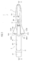
- a hair iron 1A according to this embodiment basically has a similar configuration to that of the hair iron 1 according to the above-mentioned first embodiment.
- the hair iron 1A includes the hair clip portion 2 and the grip portion 3, and in the hair iron 1A, the ion generation portions 4 and the electric charge unit 5 are provided.
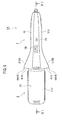
- a large different point of the hair iron 1A according to this embodiment from the hair iron 1 according to the above-mentioned first embodiment is that the pressing plate 23 shown in the above-mentioned first embodiment is not provided, and the hair clip portion 2 is solely composed of the split clip portions 21 and 22.
- the hair iron 1A according to this embodiment is provided only with a function to give the straight styling to the hair.
- the split clip portions 21 and 22 which compose the hair clip portion 2 have a flat cross-sectional shape in order to widely ensure clipping surfaces for the hair.
- the mist generation portion 4A and the fine metal particle generation potion 4B are provided in the swelling portions 312A and 312B provided on both sides of the tip end portion of the housing 311 that covers the split grip portion 31 as one of the pair, and the ions (mist and fine metal particles) generated in the mist generation portion 4A and the fine metal particle generation portion 4B are emitted from the emission ports 41A and 41B, respectively.
- the power supply switch 7A and the temperature switching switch 7B are provided; however, on the other housing 321, only the conductive member 51 is provided, and the lock switch 7C shown in the above-mentioned first embodiment is not provided. Note that it is possible to provide the lock switch 7C also in this embodiment.
- the split clip portions 21 and 22 according to this embodiment, only the opposed surfaces thereof which clip the hair just need to be heated, and only the opposed surfaces which are flattened are formed of metal having high thermal conductivity, and outsides of the split clip portions 21 and 22 are covered with covers 212 and 222 made of synthetic resin. Then, these covers 212 and 222 are attached to the housings 311 and 312 so as to continue therewith.
- the potential holding means 10 for holding the potential of the hair clip portion 2 concerned so that the potential can facilitate the ions emitted from the ion generation portions 4 to be adhered onto the hair with respect to the electric charges of the ions concerned (refer to FIG. 11 ) .
- the potential holding means 10 is provided, whereby the potential of the hair clip portion 2 is set at the potential of the opposite polarity to that of the electric charges of the ions emitted from the ion generation portions 4, and in addition, by the potential holding means 10, the potential of the hair clip portion 2 is held so as to be the same potential as the potential of the electric charge unit 5.
- the potential holding means 10 is connected to the hair clip portion 2 so that the potential of the hair clip portion 2 can be the potential of the opposite polarity to that of the electric charges of the ions emitted from the ion generations portions 4; however, it is also possible to adopt means as will be described below in order to hold the potential of the hair clip portion 2 so that the potential can facilitate the ions emitted from the ion generation portions 4 to be adhered onto the hair with respect to the electric charges of the ions concerned.
- the potential holding means 10 may be provided so as to hold the potential of the hair clip portion 2 at a level lower than the potential of the ions emitted from the ion generation portions 4. At this time, it is suitable to lower the potential of the hair clip portion 2 to an extent where the hair clip portion 2 and the ions are attracted to each other without being repelled.
- the potential holding means 10 may be provided so as to hold the potential of the hair clip portion 2 at the same potential as that of the ground. Specifically, the potential holding means 10 may be provided so that the potential of the hair clip portion 2 can be 0V by connecting the hair clip portion 2 to a ground wire.
- the ions adhered onto the hair flow outward through the ground wire. Accordingly, the potential of the hair clip portion 2 remains to be held at 0V. Then, the ions emitted from the ion generation portions 4 can be suppressed from being repelled by the hair clip portion 2, and it becomes possible to efficiently adhere the ions onto the hair.
- the potential of the hair clip portion 2 may be held at the same potential as the potential of the grip portion 3.
- the potential of the hair clip portion 2 can be held at the same potential as the potential of the grip portion 3. Accordingly, the potential of the hair clip portion 2 becomes the same potential of the user who has gripped the grip portion 3, that is, of the hair of the user, and the ions emitted from the ion generation portions 4 can be continuously irradiated onto the hair more stably. In such a way, the ions emitted from the ion generation portions can be adhered onto the hair more efficiently.
- the present invention can be embodied even in the case of using a hair iron such as a hair iron for use mainly in the case of curling the hair, which includes a hair clip portion that gives such styling to the hair, and is capable of providing the ion generation portions therein.
- a hair iron such as a hair iron for use mainly in the case of curling the hair
- a hair clip portion that gives such styling to the hair
- mist generation portion and the fine metal particle generation portion which generate the mist and the fine metal particles by the electric discharge, are illustrated in each of the above-mentioned embodiments, a steam generation mechanism that generates steam by heating water may be mounted as the mist generation portion, and a metal solution atomization mechanism that generates fine metal particles by atomizing a solution of metal may be mounted as the fine metal particle generation portion.
- specifications shapes, sizes, layout and the like
- the voltage source and other details are also be appropriately changeable.
Landscapes
- Brushes (AREA)
- Cleaning And Drying Hair (AREA)
Applications Claiming Priority (1)
| Application Number | Priority Date | Filing Date | Title |
|---|---|---|---|
| JP2009153498A JP2011005145A (ja) | 2009-06-29 | 2009-06-29 | ヘアーアイロン |
Publications (2)
| Publication Number | Publication Date |
|---|---|
| EP2269481A2 true EP2269481A2 (de) | 2011-01-05 |
| EP2269481A3 EP2269481A3 (de) | 2011-02-23 |
Family
ID=42752433
Family Applications (1)
| Application Number | Title | Priority Date | Filing Date |
|---|---|---|---|
| EP10166158A Withdrawn EP2269481A3 (de) | 2009-06-29 | 2010-06-16 | Haareisen |
Country Status (4)
| Country | Link |
|---|---|
| EP (1) | EP2269481A3 (de) |
| JP (1) | JP2011005145A (de) |
| CN (1) | CN101933703B (de) |
| RU (1) | RU2010126457A (de) |
Cited By (3)
| Publication number | Priority date | Publication date | Assignee | Title |
|---|---|---|---|---|
| WO2014095095A1 (en) * | 2012-12-18 | 2014-06-26 | Koninklijke Philips N.V. | Hair straightener |
| WO2018031605A1 (en) * | 2016-08-10 | 2018-02-15 | Spectrum Brands, Inc. | Hair styling apparatus having dual switch and lock actuator |
| WO2025236462A1 (zh) * | 2024-05-13 | 2025-11-20 | 东莞市比迪电器有限公司 | 一种直发、卷发功能的头发定型器 |
Families Citing this family (9)
| Publication number | Priority date | Publication date | Assignee | Title |
|---|---|---|---|---|
| JP5066284B1 (ja) * | 2011-05-12 | 2012-11-07 | シャープ株式会社 | 毛髪の加湿及び損傷軽減方法並びに毛髪の加湿及び損傷軽減装置 |
| JP6508624B2 (ja) * | 2014-04-11 | 2019-05-08 | パナソニックIpマネジメント株式会社 | 加熱送風装置 |
| CN104643504B (zh) * | 2015-01-26 | 2019-03-29 | 浙江百特电器有限公司 | 浮动烫发器 |
| JP6447869B2 (ja) * | 2015-03-13 | 2019-01-09 | パナソニックIpマネジメント株式会社 | 髪ケア装置 |
| GB201801605D0 (en) * | 2018-01-31 | 2018-03-14 | Paradoxx Ltd | A hair styling apparatus |
| CN111035136B (zh) * | 2020-01-15 | 2025-07-11 | 深圳市奋达科技股份有限公司 | 一种热定型器具 |
| USD999982S1 (en) | 2020-08-18 | 2023-09-26 | Conair Llc | Hair styler having a straightening iron and a curling iron |
| US11779091B2 (en) | 2020-08-18 | 2023-10-10 | Conair Llc | Hair styling apparatus with ion emitter |
| US11350720B2 (en) * | 2020-08-18 | 2022-06-07 | Conair Llc | Curling iron with ion emitter |
Citations (1)
| Publication number | Priority date | Publication date | Assignee | Title |
|---|---|---|---|---|
| JP2003059622A (ja) | 2001-08-10 | 2003-02-28 | Matsushita Electric Works Ltd | イオン供給装置及びイオン供給方法 |
Family Cites Families (6)
| Publication number | Priority date | Publication date | Assignee | Title |
|---|---|---|---|---|
| JP2003093132A (ja) * | 2001-09-25 | 2003-04-02 | Ohm Denki Kk | ヘアアイロン |
| JP4240291B2 (ja) * | 2003-05-21 | 2009-03-18 | 九州日立マクセル株式会社 | ヘアードライヤー |
| DE202004019334U1 (de) * | 2004-12-15 | 2006-04-20 | Wik Far East Ltd. | Haarpflegegerät |
| JP2006204369A (ja) * | 2005-01-25 | 2006-08-10 | Yodogawa Denki Seisakusho:Kk | ヘアーアイロン |
| JP4293211B2 (ja) * | 2006-08-31 | 2009-07-08 | パナソニック電工株式会社 | ヘアーアイロン |
| DE102007035247A1 (de) * | 2007-07-27 | 2009-02-19 | Braun Gmbh | Haarpflegegerät |
-
2009
- 2009-06-29 JP JP2009153498A patent/JP2011005145A/ja active Pending
-
2010
- 2010-06-16 EP EP10166158A patent/EP2269481A3/de not_active Withdrawn
- 2010-06-28 CN CN2010102184779A patent/CN101933703B/zh not_active Expired - Fee Related
- 2010-06-28 RU RU2010126457/12A patent/RU2010126457A/ru unknown
Patent Citations (1)
| Publication number | Priority date | Publication date | Assignee | Title |
|---|---|---|---|---|
| JP2003059622A (ja) | 2001-08-10 | 2003-02-28 | Matsushita Electric Works Ltd | イオン供給装置及びイオン供給方法 |
Cited By (4)
| Publication number | Priority date | Publication date | Assignee | Title |
|---|---|---|---|---|
| WO2014095095A1 (en) * | 2012-12-18 | 2014-06-26 | Koninklijke Philips N.V. | Hair straightener |
| RU2641873C2 (ru) * | 2012-12-18 | 2018-01-22 | Конинклейке Филипс Н.В. | Выпрямитель волос |
| WO2018031605A1 (en) * | 2016-08-10 | 2018-02-15 | Spectrum Brands, Inc. | Hair styling apparatus having dual switch and lock actuator |
| WO2025236462A1 (zh) * | 2024-05-13 | 2025-11-20 | 东莞市比迪电器有限公司 | 一种直发、卷发功能的头发定型器 |
Also Published As
| Publication number | Publication date |
|---|---|
| RU2010126457A (ru) | 2012-01-10 |
| CN101933703B (zh) | 2012-09-05 |
| EP2269481A3 (de) | 2011-02-23 |
| CN101933703A (zh) | 2011-01-05 |
| JP2011005145A (ja) | 2011-01-13 |
Similar Documents
| Publication | Publication Date | Title |
|---|---|---|
| EP2269481A2 (de) | Haareisen | |
| EP2308337A1 (de) | Haarpflegevorrichtung | |
| CN101765386B (zh) | 具有最优化离子释放的毛发护理装置 | |
| RU2354271C1 (ru) | Утюжок для волос | |
| CN108236190B (zh) | 烫发器 | |
| EP2294938B1 (de) | Haareisen, das ein Generator metallischer Teilchen umfasst | |
| WO2003061431A1 (en) | Hair setting device | |
| JP3594961B2 (ja) | 髪処理装置 | |
| JP5513080B2 (ja) | 髪ケア装置 | |
| CN102123628A (zh) | 头发护理装置 | |
| US6895686B1 (en) | Hairdryer including a ionizing device | |
| CN111298295B (zh) | 空气等离子体发生装置及具有其的医疗设备 | |
| JP4652427B2 (ja) | ヘアアイロン | |
| CN109123981B (zh) | 带电粒子发生装置和头发护理装置 | |
| JP2014212871A (ja) | ヘアケア装置 | |
| JP4678340B2 (ja) | 荷電粒子供給装置 | |
| HK1148919A (en) | Hair iron | |
| JP7616556B2 (ja) | 毛髪トリートメント装置 | |
| CN112438475A (zh) | 烫发器 | |
| CN218278922U (zh) | 一种具有离子棒的吹风机 | |
| JP2009160176A (ja) | 髪ケア装置 | |
| JP2012066217A (ja) | 静電霧化装置 |
Legal Events
| Date | Code | Title | Description |
|---|---|---|---|
| PUAI | Public reference made under article 153(3) epc to a published international application that has entered the european phase |
Free format text: ORIGINAL CODE: 0009012 |
|
| 17P | Request for examination filed |
Effective date: 20100616 |
|
| AK | Designated contracting states |
Kind code of ref document: A2 Designated state(s): AL AT BE BG CH CY CZ DE DK EE ES FI FR GB GR HR HU IE IS IT LI LT LU LV MC MK MT NL NO PL PT RO SE SI SK SM TR |
|
| AX | Request for extension of the european patent |
Extension state: BA ME RS |
|
| PUAL | Search report despatched |
Free format text: ORIGINAL CODE: 0009013 |
|
| AK | Designated contracting states |
Kind code of ref document: A3 Designated state(s): AL AT BE BG CH CY CZ DE DK EE ES FI FR GB GR HR HU IE IS IT LI LT LU LV MC MK MT NL NO PL PT RO SE SI SK SM TR |
|
| AX | Request for extension of the european patent |
Extension state: BA ME RS |
|
| RAP1 | Party data changed (applicant data changed or rights of an application transferred) |
Owner name: PANASONIC CORPORATION |
|
| STAA | Information on the status of an ep patent application or granted ep patent |
Free format text: STATUS: THE APPLICATION HAS BEEN WITHDRAWN |
|
| 18W | Application withdrawn |
Effective date: 20140612 |