EP2268527B1 - Modulare nasszelle für schienenfahrzeuge - Google Patents
Modulare nasszelle für schienenfahrzeuge Download PDFInfo
- Publication number
- EP2268527B1 EP2268527B1 EP08874029.5A EP08874029A EP2268527B1 EP 2268527 B1 EP2268527 B1 EP 2268527B1 EP 08874029 A EP08874029 A EP 08874029A EP 2268527 B1 EP2268527 B1 EP 2268527B1
- Authority
- EP
- European Patent Office
- Prior art keywords
- panels
- panel
- rail vehicle
- wet
- wet cell
- Prior art date
- Legal status (The legal status is an assumption and is not a legal conclusion. Google has not performed a legal analysis and makes no representation as to the accuracy of the status listed.)
- Active
Links
Images

Classifications
-
- B—PERFORMING OPERATIONS; TRANSPORTING
- B61—RAILWAYS
- B61D—BODY DETAILS OR KINDS OF RAILWAY VEHICLES
- B61D35/00—Sanitation
- B61D35/005—Toilet facilities
-
- Y—GENERAL TAGGING OF NEW TECHNOLOGICAL DEVELOPMENTS; GENERAL TAGGING OF CROSS-SECTIONAL TECHNOLOGIES SPANNING OVER SEVERAL SECTIONS OF THE IPC; TECHNICAL SUBJECTS COVERED BY FORMER USPC CROSS-REFERENCE ART COLLECTIONS [XRACs] AND DIGESTS
- Y10—TECHNICAL SUBJECTS COVERED BY FORMER USPC
- Y10T—TECHNICAL SUBJECTS COVERED BY FORMER US CLASSIFICATION
- Y10T428/00—Stock material or miscellaneous articles
- Y10T428/12—All metal or with adjacent metals
- Y10T428/1241—Nonplanar uniform thickness or nonlinear uniform diameter [e.g., L-shape]
-
- Y—GENERAL TAGGING OF NEW TECHNOLOGICAL DEVELOPMENTS; GENERAL TAGGING OF CROSS-SECTIONAL TECHNOLOGIES SPANNING OVER SEVERAL SECTIONS OF THE IPC; TECHNICAL SUBJECTS COVERED BY FORMER USPC CROSS-REFERENCE ART COLLECTIONS [XRACs] AND DIGESTS
- Y10—TECHNICAL SUBJECTS COVERED BY FORMER USPC
- Y10T—TECHNICAL SUBJECTS COVERED BY FORMER US CLASSIFICATION
- Y10T428/00—Stock material or miscellaneous articles
- Y10T428/24—Structurally defined web or sheet [e.g., overall dimension, etc.]
- Y10T428/24008—Structurally defined web or sheet [e.g., overall dimension, etc.] including fastener for attaching to external surface
-
- Y—GENERAL TAGGING OF NEW TECHNOLOGICAL DEVELOPMENTS; GENERAL TAGGING OF CROSS-SECTIONAL TECHNOLOGIES SPANNING OVER SEVERAL SECTIONS OF THE IPC; TECHNICAL SUBJECTS COVERED BY FORMER USPC CROSS-REFERENCE ART COLLECTIONS [XRACs] AND DIGESTS
- Y10—TECHNICAL SUBJECTS COVERED BY FORMER USPC
- Y10T—TECHNICAL SUBJECTS COVERED BY FORMER US CLASSIFICATION
- Y10T428/00—Stock material or miscellaneous articles
- Y10T428/24—Structurally defined web or sheet [e.g., overall dimension, etc.]
- Y10T428/24479—Structurally defined web or sheet [e.g., overall dimension, etc.] including variation in thickness
Definitions
- the invention relates to a modular rail vehicle wet cell.
- Wet cells in rail vehicles usually comprise a washbasin, a toilet, a shower and various accessories such as mirrors, holders for toilet paper and paper towel dispensers, holders for a toilet brush, electric hot air dryers, soap dispensers and the like.
- these wet cells are supplied by suppliers as a prefabricated unit to the rail vehicle manufacturer and installed by the latter when assembling the rail vehicle in one piece.
- Such wet cells are for example from the document FR-A1-2 800 108 known.
- the most common embodiment of wet cells for rail vehicles is the construction of the glass fiber reinforced plastic (GRP) wet cell, typically with metallic reinforcement framework.
- GRP glass fiber reinforced plastic
- the construction takes place in the usual manner for constructions made of GRP by means of a form in which layers of glass fiber fabric are inserted and impregnated with liquid, hardening plastic (epoxy or polyester resin) and removed after curing from this form.
- An optionally provided metallic reinforcing skeleton can be integrated in the construction of GFK in this manufacturing process become.
- This manufacturing method is generally used for the production of large-volume or plastic components, for example for boat hulls and superstructures, vehicles and small aircraft. The same manufacturing process also produces integrated wet rooms for hotels.
- the specific approval requirements for rolling stock mean that every material used in rail vehicles is subject to specific tests, with specific requirements being placed on the fire behavior of the materials. It is necessary to repeat these testing and approval processes each time a material used in these wet cells is changed. This makes it very difficult, for example, to replace the manufacturer of a wet cell, since the manufacturers usually each use different starting materials (glass fiber mats, resins and hardeners). Thus, even without changing the mechanical design, the production of a wet cell type is practically tied to a manufacturer, since the time and financial expenses for repeated implementation of the approval investigations make this project uneconomical.
- a major disadvantage of these wet cells produced by the construction described is that adaptations and changes (for example, integration in another vehicle type or a change in the equipment) in addition to the effort to change the design for each variant is to make their own form. As a result, a quick adaptation to customer requirements is much more difficult and associated with high costs.
- the weight of fiberglass wet cells is very high, which is particularly disadvantageous that the GFRP manufacturing process, also due to the high proportion of manual labor, produces components with unsatisfactory constant properties. Especially by varying from copy to copy wall thicknesses, it comes to significant weight differences of individual wet cells.
- the high weight has an adverse effect on further processing, in particular during transport from the manufacturer of wet cells to the manufacturer of rail vehicles and when installed in rail vehicles.
- the different wall thicknesses naturally also require different mechanical strengths of individual specimens of wet cells, or it must be prevented for this variability of strength by constructive increase in wall thicknesses.
- wet cells produced by the process described can be repaired in the event of damage only with great effort. Damage of a small scale, which is common in cases of vandalism, can be remedied with a wet cell installed in the rail vehicle. Major damage, such as after fires or massive vandalism damage cause the replacement of the wet cell. This is only possible by dismantling all the disabling parts of the rail vehicle and removing a component (typically an end wall, or parts of the outer wall or roof) of the rail vehicle. Even if it is possible by disassembling a badly damaged wet cell inside the car to expand the pieces of parts, the re-installation of a new wet cell without the removal of a component of the rail vehicle is not possible.
- the invention is therefore based on the object to provide a modular wet cell for rail vehicles, which does not have the disadvantages of the solutions according to the prior art and in particular causes no disassembly work on the affected rail vehicle in case of repair.
- the object is achieved by a wet cell with the features of claim 1.
- Advantageous embodiments are the subject of dependent claims.
- a rail vehicle wet cell is described from individual panels which form the floor, walls and ceiling of the wet cell. Any type of support structure is not required to construct a wet cell according to the invention.
- the panels consist of lightweight material approved for use in rail vehicles (e.g., so-called core composite or sandwich material, for example consisting of a high pressure laminate planked aluminum honeycomb structure) and are joined together and to the rail vehicle itself by metal profiles (typically aluminum profiles).
- core composite or sandwich material for example consisting of a high pressure laminate planked aluminum honeycomb structure
- the sandwich material to be used is any core composite material approved for use in rail vehicles.
- sandwich material from a high pressure laminate planked aluminum honeycomb structure can For example, be used with high-pressure laminate planked Polyproplylen füren or polystyrene foams.
- the use of a planking of the sandwich material made of GRP is possible.
- the panels include, in addition to the inner (honeycomb) structure and the two-sided planking edge strips of metal profiles, by means of which the connection of the panels with each other and with the rail vehicle.
- connection of the panels with each other by means of the usual, known from the general use of core composites means.
- tongue and groove joints are used in combination with a screw connection.
- connection of the panels to the rail vehicle is typically by means of vibration damping rubber / metal elements.
- Metal profiles can be used to cover the edges of the individual panels.
- the dimensions of the panels can be chosen freely, with only the dimensions of the raw material and manufacturing aspects have a limiting effect. It is advantageous to make the size of the panels so that a transport through the openings of the rail vehicle (doors, windows) is feasible.
- the necessary lines for example, electrical lines, water and sewers, hot air lines, pneumatic lines, etc.
- the necessary lines are integrated in the manufacture of the panels in these panels, wherein the line in recesses of the inner Part (eg aluminum honeycomb structure) of the sandwich material to be installed.
- the installation of cables is also possible on this (not visible) surface of the panel. This raises the advantage of having to make no installations of lines for such panels.
- wet cells for rail vehicles which can be adapted to a wide variety of installation situations without changing tools for their production (typically forms for fiberglass manufacture). Only the modification effort is required to construct another variant.
- tools for their production typically forms for fiberglass manufacture.
- exclusively conventional tools and devices for the production and processing of core composite materials are required and no forms for the production of GRP.
- panels are advantageous because the customer requirements can be better met by varying the surface design in terms of color and surface texture and yet a variety of variants can be efficiently produced.
- a wet cell constructed according to the system according to the invention comprises a panel which combines all the connections of the wet cell (typically water, sewage and electricity) at one point and at which point the connection to the rail system of the rail vehicle takes place.
- the wet cell typically water, sewage and electricity
- the assembly of the wet cell can be done (typically in the construction of rail vehicles) already outside of the rail vehicle and the wet cell can thus be installed as a whole unit, which is advantageous in new construction, since in this case the shell (end walls, roof, etc.) of the Rail vehicle is not yet closed.
- the advantage of being able to remove and repair the wet cell (eg in the case of major damage) in the installed state, that is without, for example, the end walls of the rail vehicle, is a significant advantage of the system according to the invention. Damaged panels are degradable and feasible due to their dimensions through the openings of the rail vehicle (doors, windows), so that a repair of a wet cell with much less time, and thus can be carried out cheaper.
- the production process can be designed so that all other work, especially the closing of the shell of the rail vehicle can be performed before and the installation work of the wet cell done, for example, in another manufacturing plant can.
- a wet cell according to the invention is that, even in the case that according to the intended manufacturing process of the rail vehicle, the wet cell is to be installed in one piece, an optionally not provided for the intended installation time wet cell, the further assembly work of the rail vehicle is not hindered because the wet room at any time , Can be retrofitted even with already closed shell of the rail vehicle.
- An embodiment of the panels provides to connect the panels with each other by means of a tongue and groove connection. Furthermore, the panels can also be connected by an adhesive connection, the advantage of the dismantling is eliminated.
- the most significant advantage of the system according to the invention is the significant reduction in the weight of the wet cell.
- the sandwich panels used have a significantly lower specific gravity than conventional constructions with equal mechanical strength.
- a weight saving of 30% over conventional design can be achieved. This weight saving is on the one hand during operation of the rail vehicle of advantage, since lower masses accelerated and decelerated, on the other hand affects the lower weight in the entire manufacturing process (especially during transport and installation of the wet cell).
- the panels especially panels with metallic honeycomb or foam structure
- the wet cell according to the invention is not limited to applications in which water or sewage pipes are used, as are applications that require, for example, only electrical lines, such. in the construction of baby changing rooms, Switzerlands Hughesabmaschine, luggage spaces and the like.
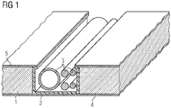
- Fig.1 shows by way of example and schematically the basic structure of a panel made of core composite material with integrated lines.
- the panel consists of a three-ply layer structure of an upper cover layer 5, a core material 1 and a lower cover layer 4.
- the upper and lower cover layers 5 and 4 may have different colors and surface structures to adapt to the particular application or the design of the other vehicle environment .
- the core material 1 consists, for example, of aluminum honeycomb material, the upper and lower cover layers 5 and 4, for example, of high-pressure laminate.
- a closed reinforcing profile 2 flat tube
- the reinforcing profile 2 is made of aluminum.
- Fig.1 the position of the reinforcing profile is shown cut in the panel.
- Leads 3 are guided in the reinforcement profile 2, in Fig.1 schematically a pipeline and three electrical lines are shown. These lines are at the required locations of the panel through openings in the reinforcing profile 2 and either the upper cover layer 5 or the lower cover layer 4 to the required position (for example, an electric lamp) out.
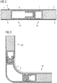
- Fig.2 shows by way of example and schematically the basic structure of a joint of two panels, typically two wall panels.
- a first panel PA which consists of a layer structure of a core material 1 and in each case an upper and lower cover layer 4, 5, is at the connection point to a second panel PB equipped with a connection profile A.
- the second panel PB has the same layer structure consisting of a core material 1 and an upper and a lower cover layer 4, 5 and is provided with a connection profile B at the connection point to the panel PB.
- the connecting profiles A, B have the same thickness as the core material 1, whereby at the edges of the panel also hardly a reduction of the mechanical strength can occur but even a support of the strength values by a possibly resulting frame construction of connecting profiles occurs.
- the connecting profiles A, B are like the reinforcing profiles 2 in the manufacture of the panel with the upper and lower cover layers 4, 5 and the core material 1 connected.
- the connection profiles A, B have a tongue and groove connection and by means of a screw (in Fig. 2 not shown) detachably connected to each other.
- the screw can be made perpendicular to the panel level or provided in the panel level.
- the connecting profile of one of the panels is provided with a threaded hole and the other panel with a recess in at least one of the cover layers 4, 5 and the connection profile of this panel through which a screw performed or the screw head is reached.
- a cover of the butt joint of two panels is provided by means of a cover profile made of metal (in Fig. 2 not shown), which cover profile may be designed in such a way that it also covers the openings for actuating the screw head.
- Figure 3 shows by way of example and schematically the basic structure of a joint between a floor and a wall panel. Junctions between wall and ceiling panels and all edges of a wet cell are realized by the same method.
- a corner profile EP typically made of aluminum, has receiving points, in which the corresponding Connecting profiles of the wall panel WP and the bottom panel BP introduced and releasably connected to each other with a screw (tongue and groove connection).
- a screw is shown perpendicular to the respective panel level.
- a floor covering 8 is applied to the floor panel BP and is guided on the wall panel to the upper edge of the corner profile EP and typically glued to the corner profile EP.
- FIG. 4 shows by way of example and schematically the basic installation of a wet cell in a rail vehicle.
- a wet cell of wall panels WP, floor panels BP and ceiling panels (not shown) is suitably attached to the structure of the rail vehicle SFZ.
- the joints between individual wall panels WP are ind Fig. 4 not shown.
- the wet cell comprises as internals a toilet T, a sink WB, a faucet WH, a handle GR and a drain AB.
- the entrance to the wet cell is covered on the bottom side with a threshold SW, typically made of metal.
- a sliding door ST is mounted in a double-walled construction of wall panels WP.
- typical fixtures such as lighting, electrical switches, outlets of hot air ducts of hand dryers are not shown.
- Figure 5 shows by way of example and schematically the basic structure of a panel.
- the panel consists of a three-layered layer structure of an upper cover layer 5, a core material 1 and a lower cover layer 4.
- a closed reinforcing profile 2 flat tube
- a closed reinforcing profile 2 flat tube
Landscapes
- Health & Medical Sciences (AREA)
- Epidemiology (AREA)
- General Health & Medical Sciences (AREA)
- Public Health (AREA)
- Engineering & Computer Science (AREA)
- Mechanical Engineering (AREA)
- Body Structure For Vehicles (AREA)
- Laminated Bodies (AREA)
- Residential Or Office Buildings (AREA)
- Floor Finish (AREA)
Description
- Die Erfindung betrifft eine modulare Schienenfahrzeugnasszelle.
- Nasszellen in Schienenfahrzeugen umfassen üblicherweise ein Waschbecken, eine Toilette, Dusche und diverses Zubehör wie Spiegel, Halterungen für Toilettenpapier und Papierhandtuchspender, Halterungen für eine Toilettenbürste, elektrische Warmlufthändetrockner, Seifenspender und ähnliches. Typischerweise werden diese Nasszellen von Zulieferfirmen als vorgefertigte Einheit an den Schienenfahrzeughersteller geliefert und von diesem bei der Montage des Schienenfahrzeugs in einem Stück eingebaut. Solche Nasszellen sind zum Beispiel aus dem Dokument
FR-A1-2 800 108 - Die spezifischen Zulassungsanforderungen für Schienenfahrzeuge bedingen es, das jedes in Schienenfahrzeugen eingesetzte Material spezifischen Untersuchungen unterworfen werden, wobei besonders an das Brandverhalten der Materialien bestimmte Anforderungen gestellt werden. Es ist erforderlich, bei jeder Änderung eines in diesen Nasszellen eingesetzten Materials diese Prüf- und Zulassungsprozesse zu wiederholen. Dadurch wird es beispielsweise sehr erschwert den Hersteller einer Nasszelle zu ersetzen, da die Hersteller üblicherweise jeweils andere Ausgangsmaterialien (Glasfasermatten, Harze und Härter) verwenden. Somit ist auch ohne Änderung der mechanischen Konstruktion die Fertigung eines Nasszellentyps praktisch an einen Hersteller gebunden, da die zeitlichen und finanziellen Aufwände zur wiederholten Durchführung der Zulassungsuntersuchungen dieses Vorhaben unwirtschaftlich machen.
- Ein wesentlicher Nachteil dieser nach der beschriebenen Bauweise hergestellten Nasszellen ist es, dass Adaptionen und Änderungen (beispielsweise die Integration in einen anderen Fahrzeugtyp oder eine Änderung der Ausstattung) neben dem Aufwand zur Änderung der Konstruktion auch für jede Variante eine eigene Form anzufertigen ist. Dadurch ist ein rasches Anpassen an Kundenwünsche wesentlich erschwert und mit hohem Aufwand verbunden.
- Ebenso ist das Gewicht von GFK Nasszellen sehr hoch, wobei sich besonders nachteilig auswirkt, dass der GFK-Fertigungsprozess, auch durch den hohen Anteil an manueller Arbeit, Bauteile mit nicht zufriedenstellend konstanten Eigenschaften erzeugt. Besonders durch von Exemplar zu Exemplar abweichende Wandstärken kommt es zu wesentlichen Gewichtsunterschieden einzelner Nasszellen. Das hohe Gewicht wirkt sich bei der weiteren Verarbeitung, insbesondere beim Transport vom Hersteller der Nasszellen zum Hersteller der Schienenfahrzeuge sowie beim Einbau in die Schienenfahrzeuge nachteilig aus. Die unterschiedlichen Wandstärken bedingen naturgemäß auch unterschiedliche mechanische Festigkeiten einzelner Exemplare von Nasszellen, bzw. es muß für diese Variabilität der Festigkeit mittels konstruktiver Erhöhung der Wandstärken vorgebeugt werden.
- Weiters sind nach dem beschriebenen Verfahren hergestellte Nasszellen im Beschädigungsfall nur mit hohem Aufwand zu reparieren. Beschädigungen kleinen Ausmaßes, wie sie in Fällen von Vandalismus häufig sind, können bei im Schienenfahrzeug eingebauter Nasszelle behoben werden. Größere Beschädigungen, etwa nach Bränden oder massive Vandalismusschäden bedingen den Austausch der Nasszelle. Dies ist nur durch den Abbau aller den Ausbau behindernden Teile des Schienenfahrzeugs und dem Entfernen einer Komponente (typischerweise einer Stirnwand, oder Teile der Außenwand oder des Daches) des Schienenfahrzeugs möglich. Selbst wenn es durch Zerkleinern einer stark beschädigten Nasszelle im Wageninneren gelingt die Teilestücke auszubauen, so ist der Wiedereinbau einer neuen Nasszelle ohne dem Entfernen einer Komponente des Schienenfahrzeugs nicht möglich.
- Der Erfindung liegt daher die Aufgabe zugrunde, eine modulare Nasszelle für Schienenfahrzeuge anzugeben, welches die Nachteile der Lösungen gemäß dem Stand der Technik nicht aufweist und insbesondere im Reparaturfall keine Zerlegungsarbeiten am betroffenen Schienenfahrzeug hervorruft.
Die Aufgabe wird durch eine Nasszelle mit den Merkmalen des Anspruchs 1 gelöst. Vorteilhafte Ausgestaltungen sind Gegenstand von abhängigen Ansprüchen. - Dem Grundgedanken der Erfindung nach wird eine Schienenfahrzeugnasszelle aus einzelnen Paneelen beschrieben, welche Boden, Wände und Decke der Nasszelle bilden.
Eine wie auch immer geartete Stützkonstruktion ist zum Aufbau einer erfindungsgemäßen Nasszelle nicht erforderlich. - Die Paneele bestehen aus leichtem, für die Verwendung in Schienenfahrzeugen zugelassenem Material (z.B. sogenanntes Kernverbund- oder Sandwichmaterial, beispielsweise bestehend aus einer mit Hochdrucklaminat beplankten Aluminiumwabenstruktur) und werden untereinander und am Schienenfahrzeug selbst mittels Metallprofilen (typischerweise Aluminiumprofile) verbunden.
- Als einzusetzendes Sandwichmaterial eignet sich jedes für den Einsatz in Schienenfahrzeugen zugelassene Kernverbundmaterial. Neben Sandwichmaterial aus einer mit Hochdrucklaminat beplankten Aluminiumwabenstruktur können beispielsweise mit Hochdrucklaminat beplankte Polyproplylenstrukturen oder Polystyrolschäume eingesetzt werden. Ebenso ist die Verwendung einer Beplankung des Sandwichmaterials aus GFK möglich.
Die Paneele umfassen neben der inneren (Waben)Struktur und der beidseitigen Beplankung Randleisten aus Metallprofilen, mittels welcher die Verbindung der Paneele untereinander und mit dem Schienenfahrzeug erfolgt. - Die Verbindung der Paneele untereinander erfolgt mittels der üblichen, aus der allgemeinen Verwendung von Kernverbundwerkstoffen bekannten Mittel. Typischerweise werden dazu Nut- Feder Verbindungen in Kombination mit einer Schraubverbindung eingesetzt.
- Die Verbindung der Paneele mit dem Schienenfahrzeug erfolgt typischerweise mittels schwingungsdämpfenden Gummi/Metallelementen.
- Zur Abdeckung der Stoßkanten der einzelnen Paneele könnenMetallprofile eingesetzt werden. Die Abmessungen der Paneele können frei gewählt werden, wobei nur die Abmessungen des Rohmaterials und fertigungstechnische Gesichtspunkte limitierend wirken. Es ist vorteilhaft, die Größe der Paneele so zu gestalten, dass ein Transport durch die Öffnungen des Schienenfahrzeugs (Türen, Fenster) durchführbar ist.
- Erfindungsgemäß werden die erforderlichen Leitungen (beispielsweise elektrische Leitungen, Wasser- und Abwasserleitungen, Warmluftleitungen, pneumatische Leitungen, etc.) bei der Fertigung der Paneele in diese Paneele integriert, wobei die Leitung in Ausnehmungen des inneren Teils (z.B. Aluminiumwabenstruktur) des Sandwichmaterials eingebaut werden.
In bestimmten Anwendungsfällen, besonders wenn ein konkretes Paneel keine sogenannten Sichtflächen (im Einsatz freiliegende Flächen, an welche ästhetische Anforderungen gestellt werden) aufweist, ist die Montage von Leitungen auch an dieser (nicht sichtbaren) Oberfläche des Paneels möglich. Dabei stellt sich der Vorteil ein, für solche Paneele keine Einbauten von Leitungen vornehmen zu müssen. - Mittels der erfindungsgemäßen Lösung ist es möglich, Nasszellen für Schienenfahrzeuge aufzubauen, welche ohne Änderung von Werkzeugen zu deren Herstellung (typischerweise Formen für die GFK-Herstellung) an verschiedenste Einbausituationen angepasst werden können. Dabei ist nur der Änderungsaufwand zur Konstruktion einer weiteren Variante erforderlich. Zur Herstellung erfindungsgemäßer Nasszellen sind ausschließlich herkömmliche Werkzeuge und Vorrichtungen zur Herstellung und Verarbeitung von Kernverbundmaterialien erforderlich und keinerlei Formen zur GFK-Herstellung.
- Durch die Verwendung von für Schienenfahrzeuge zugelassenen Materialen kann eine Vielzahl an Varianten der Nasszellen hergestellt werden, ohne die aufwendigen Zulassungsprüfungen wiederholen zu müssen. Dabei ist es besonders vorteilhaft nicht brennbare Materialien einzusetzen.
- Der Einsatz von Paneelen (aus Sandwichelementen) ist vorteilhaft, da durch Variation der Oberflächengestaltung in Hinsicht auf Farbgebung und Oberflächenstruktur die Kundenanforderungen besser erfüllbar sind und trotzdem eine Vielzahl von Varianten effizient hergestellt werden können.
- Es ist vorgesehen, die Paneele mit den für die Nasszellen notwendigen Einbauten (Wasser-, Abwasser-, Luft-, Hydraulik- oder Elektroleitungen) und Zubehörteilen (z.B. Spiegel) auszustatten. Dadurch wird die Montage dieser Einbauten und Zubehörteile wesentlich erleichtert, da sie bereits außerhalb des Schienenfahrzeugs erfolgen kann. Ebenso werden die Verrohrung von Wasser- und Abwasserleitungen sowie die elektrischen Leitungen und alle anderen Leitungen bereits während der Fertigung der Paneele in diese Paneele eingebaut.
- Vorteilhafterweise umfasst eine nach dem erfindungsgemäßen System aufgebaute Nasszelle ein Paneel, welches alle Anschlüsse der Nasszelle (typischerweise Wasser, Abwasser und Elektrizität) an einer Stelle zusammenfasst und wobei an dieser Stelle der Zusammenschluß mit dem Leitungssystem des Schienenfahrzeugs erfolgt.
- Der Zusammenbau der Nasszelle kann (typischerweise beim Neubau von Schienenfahrzeugen) bereits außerhalb des Schienenfahrzeugs erfolgen und die Nasszelle kann somit als ganze Einheit eingebaut werden, was bei Neubau von Vorteil ist, da in diesem Fall die Hülle (Stirnwände, Dach, etc.) des Schienenfahrzeugs noch nicht geschlossen ist. Der Vorteil, die Nasszelle (etwa im Falle einer größeren Beschädigung) in eingebautem Zustand, also ohne z.B. die Stirnwände des Schienenfahrzeugs zu entfernen und reparieren zu können ist ein wesentlicher Vorteil des erfindungsgemäßen Systems. Beschädigte Paneele sind abbaubar und aufgrund ihrer Abmessungen durch die Öffnungen des Schienenfahrzeugs (Türen, Fenster) durchführbar, sodass eine Reparatur einer Nasszelle mit wesentlich geringerem Zeitaufwand, und somit billiger durchgeführt werden kann.
- Ebenso ist es vorteilhaft, die Nasszelle erst im Schienenfahrzeug aufzubauen, da in diesem Fall der Produktionsablauf so gestaltet werden kann, das alle anderen Arbeiten, besonders das Verschließen der Hülle des Schienenfahrzeugs vorher durchgeführt werden können und die Einbauarbeiten der Nasszelle beispielsweise in einem anderen Fertigungsbetrieb erfolgen können.
- Ein weiterer wesentlicher Vorteil einer erfindungsgemäßen Nasszelle ist es, das auch im Fall, dass gemäß dem vorgesehenen Fertigungsablauf des Schienenfahrzeugs die Nasszelle in einem Stück einzubauen ist, eine gegebenenfalls zum vorgesehenen Einbauzeitpunkt nicht vorhandene Nasszelle die weiteren Montagearbeiten des Schienenfahrzeugs nicht behindert, da die Nasszelle jederzeit, auch bei bereits geschlossener Hülle des Schienenfahrzeugs nachträglich einbaubar ist.
- Eine Ausführungsform der Paneele sieht vor, die Paneele untereinander mittels einer Nut-Feder Verbindung zu verbinden. Weiters können die Paneele auch durch eine Klebeverbindung verbunden werden, wobei der Vorteil der Zerlegbarkeit entfällt.
- Der wesentlichste Vorteil des erfindungsgemäßen Systems ist die deutliche Reduktion des Gewichts der Nasszelle. Die verwendeten Paneele in Sandwichbauart besitzen ein deutlich geringeres spezifischeres Gewicht als konventionelle Konstruktionen mit gleicher mechanischer Festigkeit. Typischerweise kann eine Gewichtseinsparung von 30% gegenüber konventioneller Bauart erzielt werden. Diese Gewichtseinsparung ist einerseits beim Betrieb des Schienenfahrzeugs von Vorteil, da geringere Massen beschleunigt und verzögert werden müssen, andererseits wirkt sich das geringere Gewicht im kompletten Fertigungssprozeß (besonders beim Transport und Einbau der Nasszelle) aus.
- Vorteilhaft ist auch, das Paneele (besonders Paneele mit metallischer Waben- oder Schaumstruktur) wiederverwertet (recyled) werden können.
- Weiters ist vorteilhaft, das unter Einsatz dieser Erfindung die nachträgliche Ausstattung von Schienenfahrzeugen (ohne Nasszellen) mit Nasszellen oder der einfache Austausch von (konventionellen) Nasszellen in bereits im Einsatz befindlichen Schienenfahrzeugen möglich ist.
- Die erfindungsgemäße Nasszelle ist nicht auf Anwendungsfälle beschränkt, in welchen Wasser- oder Abwasserleitungen zum Einsatz kommen, ebenso sind Anwendungsfälle umfasst, die beispielsweise nur elektrische Leitungen benötigen, wie z.B. beim Aufbau von Babywickelräumen, Zugsführerabteile, Gepäckräume und ähnliches.
- Es zeigen beispielhaft:
-
Fig. 1 die Darstellung des prinzipiellen Aufbaus eines Paneels aus Kernverbundwerkstoff mit integrierten Leitungen. -
Fig. 2 die Darstellung des prinzipiellen Aufbaus einer Verbindungsstelle zweier Paneele. -
Fig. 3 die Darstellung des prinzipiellen Aufbaus einer Verbindungsstelle zwischen Wand- und Bodenpaneelen. -
Fig. 4 die Darstellung des prinzipiellen Aufbaus einer erfindungsgemäßen Nasszelle in einem Schienenfahrzeug. -
Fig. 5 die Darstellung des prinzipiellen Aufbaus eines Paneels aus Kernverbundwerkstoff. -
Fig.1 zeigt beispielhaft und schematisch den prinzipiellen Aufbau eines Paneels aus Kernverbundwerkstoff mit integrierten Leitungen. Das Paneel besteht aus einem dreilagigen Schichtaufbau aus einer oberen Decklage 5, einem Kernmaterial 1 und einer unteren Decklage 4. Die oberen und unteren Decklagen 5 und 4 können unterschiedliche Farbgebungen und Oberflächenstrukturen aufweisen um sie an den jeweiligen Einsatzzweck bzw. das Design der weiteren Fahrzeugumgebung anzupassen. Das Kernmaterial 1 besteht beispielsweise aus Aluminiumwabenmaterial die oberen und unteren Decklagen 5 und 4 beispielsweise aus Hochdrucklaminat. In eine Ausnehmung des Kernmaterials 1 ist ein geschlossenes Verstärkungsprofil 2 (Flachrohr) eingelegt, welches die gleiche Dicke wie das Kernmaterial 1 aufweist, womit an der Position des Verstärkungsprofils kaum eine Reduktion der mechanischen Festigkeit des Paneels auftreten kann. Typischerweise ist das Verstärkungsprofil 2 aus Aluminium gefertigt. InFig.1 ist die Position des Verstärkungsprofils im Paneel geschnitten dargestellt. Leitungen 3 werden im Verstärkungsprofil 2 geführt, inFig.1 sind schematisch eine Rohrleitung und drei elektrische Leitungen dargestellt. Diese Leitungen werden an den erforderlichen Stellen des Paneels durch Öffnungen im Verstärkungsprofil 2 und entweder der oberen Decklage 5 oder der unteren Decklage 4 an die benötigte Position (beispielsweise eine elektrische Lampe) geführt. -
Fig.2 zeigt beispielhaft und schematisch den prinzipiellen Aufbau einer Verbindungsstelle zweier Paneele, typischerweise zweier Wandpaneele. Ein erstes Paneel PA, welches aus einem Schichtaufbau aus einem Kernmaterial 1 und jeweils einer oberen und unteren Decklage 4, 5 besteht, ist an der Verbindungsstelle zu einem zweiten Paneel PB mit einem Verbindungsprofil A ausgestattet. Das zweite Paneel PB weist den gleichen Schichtaufbau, bestehend aus einem Kernmaterial 1 und jeweils einer oberen und unteren Decklage 4, 5 auf und ist an der Verbindungsstelle zu Paneel PB mit einem Verbindungsprofil B ausgestattet. Die Verbindungsprofile A, B weisen dieselbe Dicke wie das Kernmaterial 1 auf, womit an den Rändern des Paneels ebenfalls kaum eine Reduktion der mechanischen Festigkeit auftreten kann sondern sogar eine Unterstützung der Festigkeitswerte durch eine gegebenenfalls entstehende Rahmenkonstruktion aus Verbindungsprofilen auftritt. Die Verbindungsprofile A, B werden wie die Verstärkungsprofile 2 bei der Herstellung des Paneels mit den oberen und unteren Decklagen 4, 5 und dem Kernmaterial 1 verbunden. Die Verbindungsprofile A, B weisen eine Nut- Federverbindung auf und werden mittels einer Schraubverbindung (inFig. 2 nicht dargestellt) lösbar miteinander verbunden. Die Schraubverbindung kann senkrecht zur Paneelebene erfolgen oder in der Paneelebene vorgesehen sein. Für eine Schraubverbindung in der Paneelebene wird das Verbindungsprofil eines der Paneele mit einer Gewindebohrung versehen und das andere Paneel mit einer Ausnehmung in mindestens einer der Decklagen 4, 5 und dem Verbindungsprofil dieses Paneels, durch welche eine Schraube durchgeführt bzw. der Schraubenkopf erreichbar ist. Optional ist eine Abdeckung der Stoßfuge zweier Paneele mittels eines Abdeckprofils aus Metall vorgesehen (inFig. 2 nicht dargestellt), wobei dieses Abdeckprofil in einer Weise gestaltet sein kann, das es die Öffnungen zur Betätigung des Schraubenkopfes ebenfalls überdeckt. -
Fig.3 zeigt beispielhaft und schematisch den prinzipiellen Aufbau einer Verbindungsstelle zwischen einem Boden- und einem Wandpaneel. Verbindungsstellen zwischen Wand- und Deckenpaneelen und alle Kanten einer Nasszelle werden nach der gleichen Methode realisiert.
Ein Eckprofil EP, typischerweise aus Aluminium gefertigt, weist Aufnahmestellen auf, in welche die entsprechenden Verbindungsprofile des Wandpaneels WP und des Bodenpaneels BP eingeführt und mit einer Schraubverbindung lösbar miteinander verbunden werden (Nut- Feder Verbindung). InFig. 3 ist beispielhaft eine Schraubverbindung senkrecht zu der jeweiligen Paneelebene dargestellt. Ein Bodenbelag 8 ist auf das Bodenpaneel BP aufgebracht und wird am Wandpaneel bis zur Oberkante des Eckprofils EP geführt und typischerweise mit dem Eckprofil EP verklebt. Durch geeignete Wahl der Dicken der Wandprofils WP und des Bodenbelags 8 kann an der Nahtstelle zwischen dem Bodenbelag 8 und dem Wandprofil ein ebener Übergang erreicht werden. -
Fig.4 zeigt beispielhaft und schematisch den prinzipiellen Einbau einer Nasszelle in ein Schienenfahrzeug. An die Struktur des Schienenfahrzeugs SFZ ist an geeigneter Stelle eine Nasszelle aus Wandpaneelen WP, Bodenpaneelen BP und Deckenpaneelen (nicht dargestellt) befestigt. Die Verbindungsstellen zwischen einzelnen Wandpaneelen WP (sieheFig. 2 ) sind indFig. 4 nicht dargestellt. Die Nasszelle umfasst als Einbauten eine Toilette T, ein Waschbecken WB, einen Wasserhahn WH, eine Griffstange GR und einen Abfluß AB. Der Eingang in die Nasszelle ist bodenseitig mit einer Schwelle SW, typischerweise aus Metall gefertigt abgedeckt. Eine Schiebetür ST ist in einer Doppelwandigen Konstruktion aus Wandpaneelen WP gelagert. Weiter für Nasszellen typische Einbauten, wie Beleuchtungen, Elektrische Schalter, Außlässe von Warmluftleitungen von Händetrocknern sind nicht dargestellt. -
Fig.5 zeigt beispielhaft und schematisch den prinzipiellen Aufbau eines Paneels. Das Paneel besteht aus einem dreilagigen Schichtaufbau aus einer oberen Decklage 5, einem Kernmaterial 1 und einer unteren Decklage 4. In eine Ausnehmung des Kernmaterials 1 ist ein geschlossenes Verstärkungsprofil 2 (Flachrohr) eingelegt, welches die gleiche Dicke wie das Kernmaterial 1 aufweist. Durch das Verstärkungsprofil 2 geführte Leitungen sind inFig. 5 nicht dargestellt. -
- 1
- Kernmaterial
- 2
- Verstärkungsprofil
- 3
- Leitungen
- 4
- Untere Decklage
- 5
- Obere Decklage
- 6
- Verbindungsprofil A
- 7
- Verbindungsprofil B
- 8
- Bodenbelag
- PA
- Paneel A
- PB
- Paneel B
- EP
- Eckpaneel
- WP
- Wandpaneel
- BP
- Bodenpaneel
- SFZ
- Struktur des Schienenfahrzeugs
- ST
- Schiebetür
- T
- Toilette
- SW
- Schwelle
- WB
- Waschbecken
- WH
- Wasserhahn
- AB
- Abfluß
- GR
- Griffstange
Claims (1)
- Modulare Schienenfahrzeugnasszelle, bestehend aus Wand-, Boden- und Deckenelementen aus Kernverbundwerkstoffen, wobei der Kernverbundwerkstoff eine obere und eine untere Decklage (4, 5) mit dazwischen angeordnetem Kernmaterial (1) aufweist und Ver- und Entsorgungsleitungen (3) vorgesehen sind, dadurch gekennzeichnet, dass in Ausnehmungen des Kernmaterials (1) der Wand-, Boden- und Deckenelemente jeweils Verstärkungsprofile (2) angeordnet sind, in denen die Ver- und Entsorgungsleitungen (3) geführt sind.
Applications Claiming Priority (2)
| Application Number | Priority Date | Filing Date | Title |
|---|---|---|---|
| AT0064208A AT506765B1 (de) | 2008-04-23 | 2008-04-23 | Modulare nasszelle für ein schienenfahrzeug |
| PCT/EP2008/065653 WO2009129869A1 (de) | 2008-04-23 | 2008-11-17 | Modulare nasszelle für schienenfahrzeuge |
Publications (2)
| Publication Number | Publication Date |
|---|---|
| EP2268527A1 EP2268527A1 (de) | 2011-01-05 |
| EP2268527B1 true EP2268527B1 (de) | 2018-01-03 |
Family
ID=40456308
Family Applications (1)
| Application Number | Title | Priority Date | Filing Date |
|---|---|---|---|
| EP08874029.5A Active EP2268527B1 (de) | 2008-04-23 | 2008-11-17 | Modulare nasszelle für schienenfahrzeuge |
Country Status (10)
| Country | Link |
|---|---|
| US (1) | US20110030576A1 (de) |
| EP (1) | EP2268527B1 (de) |
| CN (1) | CN102119098A (de) |
| AT (1) | AT506765B1 (de) |
| CA (1) | CA2722206C (de) |
| ES (1) | ES2664242T3 (de) |
| HU (1) | HUE036738T2 (de) |
| RU (1) | RU2524493C2 (de) |
| UA (1) | UA99855C2 (de) |
| WO (1) | WO2009129869A1 (de) |
Families Citing this family (10)
| Publication number | Priority date | Publication date | Assignee | Title |
|---|---|---|---|---|
| DE102011005965A1 (de) * | 2011-03-23 | 2012-09-27 | Siemens Aktiengesellschaft | Nasszelle für ein Schienenfahrzeug |
| CN102513774B (zh) * | 2011-12-07 | 2014-03-05 | 青岛四方车辆研究所有限公司 | 给排水系统检修线 |
| DE102012107730B3 (de) | 2012-08-22 | 2014-05-22 | Bombardier Transportation Gmbh | Sanitärzelle sowie Schienenfahrzeug mit Sanitärzelle |
| ES2590756T3 (es) * | 2012-10-12 | 2016-11-23 | Kärcher Futuretech GmbH | Edificio de contenedores |
| FR3025453B1 (fr) | 2014-09-04 | 2019-05-31 | Alstom Transport Technologies | Panneau en materiau composite pour un vehicule ferroviaire et procede pour fabriquer un panneau en materiau composite d'un vehicule ferroviaire |
| CN105694795B (zh) * | 2016-01-28 | 2020-04-07 | 苏州科逸住宅设备股份有限公司 | 整体浴室用墙板及其制备方法 |
| FR3063704B1 (fr) * | 2017-03-07 | 2019-04-12 | Alstom Transport Technologies | Dispositif de chauffage pour un vehicule ferroviaire, permettant le chauffage d'une cabine de toilettes en preconditionnement |
| DE102018008854B4 (de) * | 2018-11-12 | 2020-08-27 | WOLFSBERG PIONIER Söllner GmbH | Modulares Verbindungssystem |
| US11492792B2 (en) | 2020-02-03 | 2022-11-08 | Wish for WASH, LLC | Modular toilet systems and methods |
| FI20236055A1 (fi) * | 2023-09-22 | 2025-03-23 | Polarteknik Oy | Palokasettirakenne ja menetelmä sen muodostamiseksi |
Family Cites Families (55)
| Publication number | Priority date | Publication date | Assignee | Title |
|---|---|---|---|---|
| US2447272A (en) * | 1945-08-09 | 1948-08-17 | Ralph C Parkes | Insulated panel |
| US2793972A (en) * | 1954-05-24 | 1957-05-28 | Goodyear Aircraft Corp | Method of making metal-faced laminates |
| US3192671A (en) * | 1961-04-10 | 1965-07-06 | Us Stoneware Co | Panel structures |
| US3529389A (en) * | 1968-09-30 | 1970-09-22 | Comstruct Inc | Modular building wall structure with electrical raceway means |
| US3602110A (en) * | 1968-10-31 | 1971-08-31 | Republic Steel Corp | Lightweight steel land mat |
| US3712005A (en) * | 1969-12-15 | 1973-01-23 | Aztec Mfg Co | Extrusions for partitions, walls and enclosures |
| US3766574A (en) * | 1970-10-22 | 1973-10-23 | Smid H Plumbing & Heating Co I | Prefabricated plumbing partition |
| US3733102A (en) * | 1971-01-15 | 1973-05-15 | A Serino | Automobile campers |
| US3859000A (en) * | 1972-03-30 | 1975-01-07 | Reynolds Metals Co | Road construction and panel for making same |
| US3978529A (en) * | 1974-10-15 | 1976-09-07 | Systems Design & Development | Powder room and bathroom system |
| US4078348A (en) * | 1976-10-18 | 1978-03-14 | Michael Rothman | Construction panels for structural support systems |
| US4373313A (en) * | 1980-07-22 | 1983-02-15 | Nash Jr Edgar M | Water-tight rigid structural panel |
| US4557091A (en) * | 1982-02-10 | 1985-12-10 | Corflex International, Inc. | Extruded structural system |
| US4621467A (en) * | 1983-02-24 | 1986-11-11 | Eric B. Lipson | Vertical-walled edge-connected panelized connectable rhombic triacontahedral buildings |
| US4575981A (en) * | 1984-02-13 | 1986-03-18 | Porter William H | Roof panel construction |
| US4777774A (en) * | 1987-06-09 | 1988-10-18 | Smalley Iii Arthur L | Building construction utilizing plastic components |
| US4862660A (en) * | 1987-07-13 | 1989-09-05 | Raymond Harry W | Foamed panel including an internally mounted stud |
| US5076310A (en) * | 1989-02-23 | 1991-12-31 | Alexander Barenburg | Framed wall with a prefabricated underfloor drain line and method of manufacture |
| US4919164A (en) * | 1989-02-23 | 1990-04-24 | Alexander Barenburg | Method of installing piping, ducts and conduits in a prefabricated framed wall for a building structure and partition made thereby |
| US5014476A (en) * | 1989-04-07 | 1991-05-14 | Bellcomb Technologies Incorporated | Multicomponent panel system and method as assembly |
| US5228257A (en) * | 1991-03-04 | 1993-07-20 | Awh Corporation | Modular wall system |
| CA2070079C (en) * | 1992-05-29 | 1997-06-10 | Vittorio De Zen | Thermoplastic structural system and components therefor and method of making same |
| DE4301763C2 (de) * | 1993-01-23 | 1996-10-17 | Vaw Ver Aluminium Werke Ag | Wagenkastenaufbau, insbesondere für Eisenbahnwagen zur Personenbeförderung |
| US5347778A (en) * | 1993-04-07 | 1994-09-20 | Globe Business Furniture, Inc. | Partition joining system |
| US5373678A (en) * | 1994-02-22 | 1994-12-20 | Hesser; Francis J. | Structural panel system |
| US5459966A (en) * | 1994-06-17 | 1995-10-24 | Suarez; Miguel A. | Prefabricated bathroom walls |
| CA2134959C (en) * | 1994-11-02 | 2002-06-11 | Vittorio De Zen | Fire rate modular building system |
| US5600930A (en) * | 1995-04-10 | 1997-02-11 | Drucker; Ernest R. | Construction system using lightweight fire-resistant panels |
| US5724773A (en) * | 1995-09-25 | 1998-03-10 | Hall; Gerald W. | Building module providing readily accessible utility connections |
| DK171589B1 (da) * | 1996-01-19 | 1997-02-10 | Abb Daimler Benz Transp | Sanitetscelle |
| DE19619212A1 (de) * | 1996-05-13 | 1997-11-20 | Duewag Ag | Wagenkasten eines Schienenfahrzeuges |
| US5921046A (en) * | 1997-04-04 | 1999-07-13 | Recobond, Inc. | Prefabricated building system for walls, roofs, and floors using a foam core building panel and connectors |
| US6418686B1 (en) * | 1997-04-25 | 2002-07-16 | Leading Edge Earth Products, Inc. | Insulated asymmetrical directional force resistant building panel with symmetrical joinery, integral shear resistance connector and thermal break |
| CA2245624C (en) * | 1998-08-20 | 2008-01-08 | Vic De Zen | Prefabricated plastic shed and components therefor |
| US6243993B1 (en) * | 1999-03-11 | 2001-06-12 | Wellness, Llc | Modular healthcare room interior |
| US6308465B1 (en) * | 1999-06-21 | 2001-10-30 | Equitech, Inc. | Systems and utility modules for buildings |
| CN1158439C (zh) * | 1999-07-23 | 2004-07-21 | 格兰特·C·雷科德 | 无框架建筑系统及建筑物 |
| FR2800108B1 (fr) * | 1999-10-26 | 2002-01-11 | Rb Concept | Procede de fabrication de parois et cellules de batiments et les parois et cellules de batiment obtenues par sa mise en oeuvre |
| US6564521B1 (en) * | 2000-05-12 | 2003-05-20 | Brown Paul A | Structural sandwich panels and method of manufacture of structural sandwich panels |
| RU15580U1 (ru) * | 2000-07-05 | 2000-10-27 | Общество с ограниченной ответственностью "Строймода" | Сборно-разборная конструкция |
| CA2331800A1 (en) * | 2001-01-22 | 2002-07-22 | Moritz F. Gruber | Portable graphic floor system |
| GB2374038B (en) * | 2001-04-02 | 2005-03-09 | Intelligent Engineering | Improved structural sandwich plate members |
| IL148400A (en) * | 2002-02-26 | 2007-06-17 | Dynamic Shells Ltd | Modular construction and method for its construction |
| CA2501869C (en) * | 2002-10-11 | 2010-08-17 | Robert B. Douglas | Modular structure for building panels and methods of making and using same |
| US6860073B2 (en) * | 2003-01-31 | 2005-03-01 | Yaw-Jiun Chien | Structure of a combinative interlocking board enclosing vertical and horizontal pipes |
| RU43519U1 (ru) * | 2003-05-15 | 2005-01-27 | Закрытое акционерное общество "ХИУС" | Санитарно-технический комплекс транспортного средства |
| RU35999U1 (ru) * | 2003-10-20 | 2004-02-20 | Общество с ограниченной ответственностью Научно-производственное предприятие "Циркон-Сервис" | Туалетный модуль |
| JP4531671B2 (ja) * | 2005-10-12 | 2010-08-25 | 株式会社神戸製鋼所 | 中空パネル及びその製造方法 |
| US20070125042A1 (en) * | 2005-11-22 | 2007-06-07 | John Hughes | Structural insulated panel construction for building structures |
| GB0526312D0 (en) * | 2005-12-23 | 2006-02-01 | Britax Premium Aircraft Interi | Composite panel |
| RU60554U1 (ru) * | 2006-02-06 | 2007-01-27 | Максим Валерьевич Слышков | Строительное сооружение |
| US7900411B2 (en) * | 2006-02-17 | 2011-03-08 | Antonic James P | Shear wall building assemblies |
| ES2611928T3 (es) * | 2006-05-15 | 2017-05-11 | Chen-Yin Lu | Estructura de pared de tipo ensamblaje |
| US7743565B2 (en) * | 2006-11-08 | 2010-06-29 | Pyo John M | Modular building block system and method of manufacture |
| US20090293395A1 (en) * | 2008-05-30 | 2009-12-03 | Porter William H | Structural insulated panel system including junctures |
-
2008
- 2008-04-23 AT AT0064208A patent/AT506765B1/de not_active IP Right Cessation
- 2008-11-17 RU RU2010143414/11A patent/RU2524493C2/ru active
- 2008-11-17 US US12/936,400 patent/US20110030576A1/en not_active Abandoned
- 2008-11-17 EP EP08874029.5A patent/EP2268527B1/de active Active
- 2008-11-17 CA CA2722206A patent/CA2722206C/en active Active
- 2008-11-17 CN CN2008801287764A patent/CN102119098A/zh active Pending
- 2008-11-17 UA UAA201012518A patent/UA99855C2/uk unknown
- 2008-11-17 HU HUE08874029A patent/HUE036738T2/hu unknown
- 2008-11-17 ES ES08874029.5T patent/ES2664242T3/es active Active
- 2008-11-17 WO PCT/EP2008/065653 patent/WO2009129869A1/de not_active Ceased
Also Published As
| Publication number | Publication date |
|---|---|
| US20110030576A1 (en) | 2011-02-10 |
| HUE036738T2 (hu) | 2018-07-30 |
| RU2524493C2 (ru) | 2014-07-27 |
| AT506765B1 (de) | 2010-02-15 |
| EP2268527A1 (de) | 2011-01-05 |
| AT506765A1 (de) | 2009-11-15 |
| CA2722206C (en) | 2016-11-01 |
| CN102119098A (zh) | 2011-07-06 |
| UA99855C2 (uk) | 2012-10-10 |
| WO2009129869A1 (de) | 2009-10-29 |
| ES2664242T3 (es) | 2018-04-18 |
| CA2722206A1 (en) | 2009-10-29 |
| RU2010143414A (ru) | 2012-04-27 |
Similar Documents
| Publication | Publication Date | Title |
|---|---|---|
| AT506765B1 (de) | Modulare nasszelle für ein schienenfahrzeug | |
| EP0898535B2 (de) | Wagenkasten eines schienenfahrzeuges | |
| DE69700805T2 (de) | Sanitärzelle | |
| EP0577940B1 (de) | Verfahren zur integralen Herstellung eines Innenausbaus für Wagenkasten | |
| DE102007008988A1 (de) | Rumpf eines Luft-oder Raumfahrzeugs und ein entsprechendes Luft-oder Raumfahrzeug | |
| DE102012023653A1 (de) | Kraftfahrzeugkarosserie mit Leichtbauteil | |
| DE102007003277A1 (de) | Rumpf eines Luft- oder Raumfahrzeuges in CFK-Metall Hybridbauweise mit einem Metallrahmen | |
| DE102017220378A1 (de) | Bodenbaugruppe mit monolithischem Bodenelement sowie Luftfahrzeugbereich und Luftfahrzeug mit einer Bodenbaugruppe | |
| DE102010011568A1 (de) | Wagenkasten eines Schienenfahrzeugs und Verfahren zu seiner Herstellung | |
| DE102008016422B3 (de) | Anordnung in Rahmenbauweise zum Aufnehmen eines Vorhangs in einer Kabine eines Fahrzeugs | |
| DE102007061423A1 (de) | Sicherheitskabine | |
| DE102015206707A1 (de) | Monument für eine Kabine eines Fahrzeugs und Befestigungsanordnung | |
| DE102007061429B4 (de) | Rumpfstruktur | |
| WO2017050578A1 (de) | Flächiges fahrkorbelement für eine aufzugsanlage | |
| DE202007001538U1 (de) | Revisionsvorrichtung, insbesondere Revisionsabdeckung | |
| DE102011117185B4 (de) | Haltevorrichtung zur Anbringung mindestens eines Anbauteils an eine Rumpfzellenstruktur eines Luftfahrzeuges | |
| DE102007008986A1 (de) | Rumpf eines Luft-oder Raumfahrzeugs, und ein entsprechendes Luft-oder Raumfahrzeug | |
| DE29909388U1 (de) | Mehrschichtige Schnellbau-Trockenbauplatte | |
| DE102019114656A1 (de) | Abdeckungselement für eine Vorwandinstallation | |
| DE29608643U1 (de) | Wagenkasten eines Schienenfahrzeuges | |
| EP2072705A1 (de) | Holz-Beton-Verbundelement | |
| DE102004020023B4 (de) | Holzgebäude und Verfahren zu dessen Montage | |
| EP1903162B1 (de) | Revisionsvorrichtung mit einem Revisionsrahmen und einem Revisionsdeckel | |
| DE202012104085U1 (de) | Vorsatzfassade | |
| DE102019108584A1 (de) | Fertiggebäudesystem |
Legal Events
| Date | Code | Title | Description |
|---|---|---|---|
| PUAI | Public reference made under article 153(3) epc to a published international application that has entered the european phase |
Free format text: ORIGINAL CODE: 0009012 |
|
| 17P | Request for examination filed |
Effective date: 20100713 |
|
| AK | Designated contracting states |
Kind code of ref document: A1 Designated state(s): AT BE BG CH CY CZ DE DK EE ES FI FR GB GR HR HU IE IS IT LI LT LU LV MC MT NL NO PL PT RO SE SI SK TR |
|
| AX | Request for extension of the european patent |
Extension state: AL BA MK RS |
|
| DAX | Request for extension of the european patent (deleted) | ||
| GRAP | Despatch of communication of intention to grant a patent |
Free format text: ORIGINAL CODE: EPIDOSNIGR1 |
|
| STAA | Information on the status of an ep patent application or granted ep patent |
Free format text: STATUS: GRANT OF PATENT IS INTENDED |
|
| INTG | Intention to grant announced |
Effective date: 20170802 |
|
| GRAS | Grant fee paid |
Free format text: ORIGINAL CODE: EPIDOSNIGR3 |
|
| GRAA | (expected) grant |
Free format text: ORIGINAL CODE: 0009210 |
|
| STAA | Information on the status of an ep patent application or granted ep patent |
Free format text: STATUS: THE PATENT HAS BEEN GRANTED |
|
| AK | Designated contracting states |
Kind code of ref document: B1 Designated state(s): AT BE BG CH CY CZ DE DK EE ES FI FR GB GR HR HU IE IS IT LI LT LU LV MC MT NL NO PL PT RO SE SI SK TR |
|
| REG | Reference to a national code |
Ref country code: GB Ref legal event code: FG4D Free format text: NOT ENGLISH |
|
| REG | Reference to a national code |
Ref country code: CH Ref legal event code: EP Ref country code: AT Ref legal event code: REF Ref document number: 959958 Country of ref document: AT Kind code of ref document: T Effective date: 20180115 |
|
| REG | Reference to a national code |
Ref country code: IE Ref legal event code: FG4D Free format text: LANGUAGE OF EP DOCUMENT: GERMAN |
|
| REG | Reference to a national code |
Ref country code: DE Ref legal event code: R096 Ref document number: 502008015838 Country of ref document: DE |
|
| REG | Reference to a national code |
Ref country code: CH Ref legal event code: NV Representative=s name: SIEMENS SCHWEIZ AG, CH |
|
| REG | Reference to a national code |
Ref country code: ES Ref legal event code: FG2A Ref document number: 2664242 Country of ref document: ES Kind code of ref document: T3 Effective date: 20180418 |
|
| REG | Reference to a national code |
Ref country code: NL Ref legal event code: MP Effective date: 20180103 |
|
| REG | Reference to a national code |
Ref country code: LT Ref legal event code: MG4D |
|
| PG25 | Lapsed in a contracting state [announced via postgrant information from national office to epo] |
Ref country code: NL Free format text: LAPSE BECAUSE OF FAILURE TO SUBMIT A TRANSLATION OF THE DESCRIPTION OR TO PAY THE FEE WITHIN THE PRESCRIBED TIME-LIMIT Effective date: 20180103 |
|
| REG | Reference to a national code |
Ref country code: HU Ref legal event code: AG4A Ref document number: E036738 Country of ref document: HU |
|
| PG25 | Lapsed in a contracting state [announced via postgrant information from national office to epo] |
Ref country code: FI Free format text: LAPSE BECAUSE OF FAILURE TO SUBMIT A TRANSLATION OF THE DESCRIPTION OR TO PAY THE FEE WITHIN THE PRESCRIBED TIME-LIMIT Effective date: 20180103 Ref country code: CY Free format text: LAPSE BECAUSE OF FAILURE TO SUBMIT A TRANSLATION OF THE DESCRIPTION OR TO PAY THE FEE WITHIN THE PRESCRIBED TIME-LIMIT Effective date: 20180103 Ref country code: NO Free format text: LAPSE BECAUSE OF FAILURE TO SUBMIT A TRANSLATION OF THE DESCRIPTION OR TO PAY THE FEE WITHIN THE PRESCRIBED TIME-LIMIT Effective date: 20180403 Ref country code: LT Free format text: LAPSE BECAUSE OF FAILURE TO SUBMIT A TRANSLATION OF THE DESCRIPTION OR TO PAY THE FEE WITHIN THE PRESCRIBED TIME-LIMIT Effective date: 20180103 Ref country code: HR Free format text: LAPSE BECAUSE OF FAILURE TO SUBMIT A TRANSLATION OF THE DESCRIPTION OR TO PAY THE FEE WITHIN THE PRESCRIBED TIME-LIMIT Effective date: 20180103 |
|
| PG25 | Lapsed in a contracting state [announced via postgrant information from national office to epo] |
Ref country code: SE Free format text: LAPSE BECAUSE OF FAILURE TO SUBMIT A TRANSLATION OF THE DESCRIPTION OR TO PAY THE FEE WITHIN THE PRESCRIBED TIME-LIMIT Effective date: 20180103 Ref country code: BG Free format text: LAPSE BECAUSE OF FAILURE TO SUBMIT A TRANSLATION OF THE DESCRIPTION OR TO PAY THE FEE WITHIN THE PRESCRIBED TIME-LIMIT Effective date: 20180403 Ref country code: IS Free format text: LAPSE BECAUSE OF FAILURE TO SUBMIT A TRANSLATION OF THE DESCRIPTION OR TO PAY THE FEE WITHIN THE PRESCRIBED TIME-LIMIT Effective date: 20180503 Ref country code: LV Free format text: LAPSE BECAUSE OF FAILURE TO SUBMIT A TRANSLATION OF THE DESCRIPTION OR TO PAY THE FEE WITHIN THE PRESCRIBED TIME-LIMIT Effective date: 20180103 Ref country code: GR Free format text: LAPSE BECAUSE OF FAILURE TO SUBMIT A TRANSLATION OF THE DESCRIPTION OR TO PAY THE FEE WITHIN THE PRESCRIBED TIME-LIMIT Effective date: 20180404 Ref country code: PL Free format text: LAPSE BECAUSE OF FAILURE TO SUBMIT A TRANSLATION OF THE DESCRIPTION OR TO PAY THE FEE WITHIN THE PRESCRIBED TIME-LIMIT Effective date: 20180103 |
|
| PG25 | Lapsed in a contracting state [announced via postgrant information from national office to epo] |
Ref country code: MT Free format text: LAPSE BECAUSE OF FAILURE TO SUBMIT A TRANSLATION OF THE DESCRIPTION OR TO PAY THE FEE WITHIN THE PRESCRIBED TIME-LIMIT Effective date: 20180103 |
|
| REG | Reference to a national code |
Ref country code: DE Ref legal event code: R097 Ref document number: 502008015838 Country of ref document: DE |
|
| PG25 | Lapsed in a contracting state [announced via postgrant information from national office to epo] |
Ref country code: EE Free format text: LAPSE BECAUSE OF FAILURE TO SUBMIT A TRANSLATION OF THE DESCRIPTION OR TO PAY THE FEE WITHIN THE PRESCRIBED TIME-LIMIT Effective date: 20180103 Ref country code: RO Free format text: LAPSE BECAUSE OF FAILURE TO SUBMIT A TRANSLATION OF THE DESCRIPTION OR TO PAY THE FEE WITHIN THE PRESCRIBED TIME-LIMIT Effective date: 20180103 |
|
| PLBE | No opposition filed within time limit |
Free format text: ORIGINAL CODE: 0009261 |
|
| STAA | Information on the status of an ep patent application or granted ep patent |
Free format text: STATUS: NO OPPOSITION FILED WITHIN TIME LIMIT |
|
| PG25 | Lapsed in a contracting state [announced via postgrant information from national office to epo] |
Ref country code: SK Free format text: LAPSE BECAUSE OF FAILURE TO SUBMIT A TRANSLATION OF THE DESCRIPTION OR TO PAY THE FEE WITHIN THE PRESCRIBED TIME-LIMIT Effective date: 20180103 Ref country code: DK Free format text: LAPSE BECAUSE OF FAILURE TO SUBMIT A TRANSLATION OF THE DESCRIPTION OR TO PAY THE FEE WITHIN THE PRESCRIBED TIME-LIMIT Effective date: 20180103 |
|
| 26N | No opposition filed |
Effective date: 20181005 |
|
| PG25 | Lapsed in a contracting state [announced via postgrant information from national office to epo] |
Ref country code: SI Free format text: LAPSE BECAUSE OF FAILURE TO SUBMIT A TRANSLATION OF THE DESCRIPTION OR TO PAY THE FEE WITHIN THE PRESCRIBED TIME-LIMIT Effective date: 20180103 |
|
| REG | Reference to a national code |
Ref country code: CH Ref legal event code: PUE Owner name: SIEMENS MOBILITY GMBH, AT Free format text: FORMER OWNER: SIEMENS AG OESTERREICH, AT |
|
| REG | Reference to a national code |
Ref country code: DE Ref legal event code: R082 Ref document number: 502008015838 Country of ref document: DE Representative=s name: DEFFNER, ROLF, DR., DE Ref country code: DE Ref legal event code: R081 Ref document number: 502008015838 Country of ref document: DE Owner name: SIEMENS MOBILITY GMBH, AT Free format text: FORMER OWNER: SIEMENS AG OESTERREICH, WIEN, AT Ref country code: DE Ref legal event code: R081 Ref document number: 502008015838 Country of ref document: DE Owner name: SIEMENS MOBILITY AUSTRIA GMBH, AT Free format text: FORMER OWNER: SIEMENS AG OESTERREICH, WIEN, AT |
|
| GBPC | Gb: european patent ceased through non-payment of renewal fee |
Effective date: 20181117 |
|
| PG25 | Lapsed in a contracting state [announced via postgrant information from national office to epo] |
Ref country code: LU Free format text: LAPSE BECAUSE OF NON-PAYMENT OF DUE FEES Effective date: 20181117 Ref country code: MC Free format text: LAPSE BECAUSE OF FAILURE TO SUBMIT A TRANSLATION OF THE DESCRIPTION OR TO PAY THE FEE WITHIN THE PRESCRIBED TIME-LIMIT Effective date: 20180103 |
|
| REG | Reference to a national code |
Ref country code: BE Ref legal event code: MM Effective date: 20181130 |
|
| REG | Reference to a national code |
Ref country code: IE Ref legal event code: MM4A |
|
| REG | Reference to a national code |
Ref country code: AT Ref legal event code: PC Ref document number: 959958 Country of ref document: AT Kind code of ref document: T Owner name: SIEMENS MOBILITY GMBH, AT Effective date: 20190814 |
|
| PG25 | Lapsed in a contracting state [announced via postgrant information from national office to epo] |
Ref country code: IE Free format text: LAPSE BECAUSE OF NON-PAYMENT OF DUE FEES Effective date: 20181117 |
|
| PG25 | Lapsed in a contracting state [announced via postgrant information from national office to epo] |
Ref country code: BE Free format text: LAPSE BECAUSE OF NON-PAYMENT OF DUE FEES Effective date: 20181130 |
|
| REG | Reference to a national code |
Ref country code: DE Ref legal event code: R082 Ref document number: 502008015838 Country of ref document: DE Representative=s name: DEFFNER, ROLF, DR., DE Ref country code: DE Ref legal event code: R081 Ref document number: 502008015838 Country of ref document: DE Owner name: SIEMENS MOBILITY AUSTRIA GMBH, AT Free format text: FORMER OWNER: SIEMENS MOBILITY GMBH, WIEN, AT |
|
| REG | Reference to a national code |
Ref country code: CH Ref legal event code: PFA Owner name: SIEMENS MOBILITY AUSTRIA GMBH, AT Free format text: FORMER OWNER: SIEMENS MOBILITY GMBH, AT |
|
| PG25 | Lapsed in a contracting state [announced via postgrant information from national office to epo] |
Ref country code: GB Free format text: LAPSE BECAUSE OF NON-PAYMENT OF DUE FEES Effective date: 20181117 |
|
| PG25 | Lapsed in a contracting state [announced via postgrant information from national office to epo] |
Ref country code: TR Free format text: LAPSE BECAUSE OF FAILURE TO SUBMIT A TRANSLATION OF THE DESCRIPTION OR TO PAY THE FEE WITHIN THE PRESCRIBED TIME-LIMIT Effective date: 20180103 |
|
| REG | Reference to a national code |
Ref country code: ES Ref legal event code: PC2A Owner name: SIEMENS MOBILITY AUSTRIA GMBH Effective date: 20200414 |
|
| REG | Reference to a national code |
Ref country code: HU Ref legal event code: FH1C Free format text: FORMER REPRESENTATIVE(S): SBGK SZABADALMI UEGYVIVOEI IRODA, HU Representative=s name: SBGK SZABADALMI UEGYVIVOEI IRODA, HU Ref country code: HU Ref legal event code: GB9C Owner name: SIEMENS MOBILITY AUSTRIA GMBH, AT Free format text: FORMER OWNER(S): SIEMENS AG OESTERREICH, AT |
|
| PG25 | Lapsed in a contracting state [announced via postgrant information from national office to epo] |
Ref country code: PT Free format text: LAPSE BECAUSE OF FAILURE TO SUBMIT A TRANSLATION OF THE DESCRIPTION OR TO PAY THE FEE WITHIN THE PRESCRIBED TIME-LIMIT Effective date: 20180103 |
|
| REG | Reference to a national code |
Ref country code: AT Ref legal event code: HC Ref document number: 959958 Country of ref document: AT Kind code of ref document: T Owner name: SIEMENS MOBILITY AUSTRIA GMBH, AT Effective date: 20211108 |
|
| PGFP | Annual fee paid to national office [announced via postgrant information from national office to epo] |
Ref country code: HU Payment date: 20240123 Year of fee payment: 16 |
|
| PG25 | Lapsed in a contracting state [announced via postgrant information from national office to epo] |
Ref country code: HU Free format text: LAPSE BECAUSE OF NON-PAYMENT OF DUE FEES Effective date: 20241118 |
|
| PGFP | Annual fee paid to national office [announced via postgrant information from national office to epo] |
Ref country code: AT Payment date: 20251014 Year of fee payment: 18 |
|
| PGFP | Annual fee paid to national office [announced via postgrant information from national office to epo] |
Ref country code: IT Payment date: 20251125 Year of fee payment: 18 |
|
| PGFP | Annual fee paid to national office [announced via postgrant information from national office to epo] |
Ref country code: FR Payment date: 20251114 Year of fee payment: 18 |
|
| PGFP | Annual fee paid to national office [announced via postgrant information from national office to epo] |
Ref country code: CZ Payment date: 20251111 Year of fee payment: 18 |
|
| REG | Reference to a national code |
Ref country code: CH Ref legal event code: U11 Free format text: ST27 STATUS EVENT CODE: U-0-0-U10-U11 (AS PROVIDED BY THE NATIONAL OFFICE) Effective date: 20260209 |
|
| PGFP | Annual fee paid to national office [announced via postgrant information from national office to epo] |
Ref country code: ES Payment date: 20260220 Year of fee payment: 18 |
|
| PGFP | Annual fee paid to national office [announced via postgrant information from national office to epo] |
Ref country code: DE Payment date: 20260119 Year of fee payment: 18 |
|
| PGFP | Annual fee paid to national office [announced via postgrant information from national office to epo] |
Ref country code: CH Payment date: 20260209 Year of fee payment: 18 |