EP2267668B1 - Bill depositing/withdrawing apparatus - Google Patents
Bill depositing/withdrawing apparatus Download PDFInfo
- Publication number
- EP2267668B1 EP2267668B1 EP10010106A EP10010106A EP2267668B1 EP 2267668 B1 EP2267668 B1 EP 2267668B1 EP 10010106 A EP10010106 A EP 10010106A EP 10010106 A EP10010106 A EP 10010106A EP 2267668 B1 EP2267668 B1 EP 2267668B1
- Authority
- EP
- European Patent Office
- Prior art keywords
- bill
- bills
- cash slot
- user
- depositing
- Prior art date
- Legal status (The legal status is an assumption and is not a legal conclusion. Google has not performed a legal analysis and makes no representation as to the accuracy of the status listed.)
- Not-in-force
Links
Images


Classifications
-
- G—PHYSICS
- G07—CHECKING-DEVICES
- G07F—COIN-FREED OR LIKE APPARATUS
- G07F19/00—Complete banking systems; Coded card-freed arrangements adapted for dispensing or receiving monies or the like and posting such transactions to existing accounts, e.g. automatic teller machines
-
- G—PHYSICS
- G07—CHECKING-DEVICES
- G07F—COIN-FREED OR LIKE APPARATUS
- G07F19/00—Complete banking systems; Coded card-freed arrangements adapted for dispensing or receiving monies or the like and posting such transactions to existing accounts, e.g. automatic teller machines
- G07F19/20—Automatic teller machines [ATMs]
- G07F19/203—Dispensing operations within ATMs
-
- B—PERFORMING OPERATIONS; TRANSPORTING
- B65—CONVEYING; PACKING; STORING; HANDLING THIN OR FILAMENTARY MATERIAL
- B65H—HANDLING THIN OR FILAMENTARY MATERIAL, e.g. SHEETS, WEBS, CABLES
- B65H31/00—Pile receivers
- B65H31/30—Arrangements for removing completed piles
- B65H31/3027—Arrangements for removing completed piles by the nip between moving belts or rollers
-
- G—PHYSICS
- G07—CHECKING-DEVICES
- G07D—HANDLING OF COINS OR VALUABLE PAPERS, e.g. TESTING, SORTING BY DENOMINATIONS, COUNTING, DISPENSING, CHANGING OR DEPOSITING
- G07D11/00—Devices accepting coins; Devices accepting, dispensing, sorting or counting valuable papers
- G07D11/10—Mechanical details
- G07D11/14—Inlet or outlet ports
-
- G—PHYSICS
- G07—CHECKING-DEVICES
- G07D—HANDLING OF COINS OR VALUABLE PAPERS, e.g. TESTING, SORTING BY DENOMINATIONS, COUNTING, DISPENSING, CHANGING OR DEPOSITING
- G07D9/00—Counting coins; Handling of coins not provided for in the other groups of this subclass
-
- G—PHYSICS
- G07—CHECKING-DEVICES
- G07F—COIN-FREED OR LIKE APPARATUS
- G07F19/00—Complete banking systems; Coded card-freed arrangements adapted for dispensing or receiving monies or the like and posting such transactions to existing accounts, e.g. automatic teller machines
- G07F19/20—Automatic teller machines [ATMs]
- G07F19/202—Depositing operations within ATMs
-
- B—PERFORMING OPERATIONS; TRANSPORTING
- B65—CONVEYING; PACKING; STORING; HANDLING THIN OR FILAMENTARY MATERIAL
- B65H—HANDLING THIN OR FILAMENTARY MATERIAL, e.g. SHEETS, WEBS, CABLES
- B65H2408/00—Specific machines
- B65H2408/10—Specific machines for handling sheet(s)
- B65H2408/13—Wall or kiosk dispenser, i.e. for positively handling or holding material until withdrawal by user
Abstract
Description
- The present invention relates to a bill depositing/withdrawing apparatus, which handles, for example, a bill or bills.
- Conventionally, a bill depositing/withdrawing apparatus is mounted in an automated transaction machine used in financial institutions, and the like. The bill depositing/ withdrawing apparatus comprises a cash slot for allowing a user to deposit/withdraw a bill or bills, a bill discriminator for discrimination of a bill, and a bill conveyance path, which passes the bill discriminator and conveys a bill or bills. Also, the bill depositing/withdrawing apparatus comprises a combination of respective units, such as a temporary stacker for temporarily storing a deposited bill or bills, a deposit box for storing a deposited bill or bills, a withdrawal box, from which a bill or bills for withdrawal are fed, a recycle box for storing and feeding a bill or bills for deposits and withdrawals, a reject box for storing a bill or bills, which are not to be stored in the deposit box and the recycle box, and a bill or bills, which are not to be withdrawn, out of a bill or bills fed from the withdrawal box, and a load/collect box for feeding a bill or bills being supplied to the recycle box and storing a bill or bills collected from the recycle box.
- Along with the popularization of automatic transaction machines, there is heightened a need of making such bill depositing/withdrawing apparatus small in size, inexpensive, and convenient in use while ensuring conventional functions and performances.
- Also, along with increase in handling foreign bills in the country and in needs for bill depositing/withdrawing apparatus in the foreign countries, there are demanded for bill depositing/withdrawing apparatus capable of handling not only Japanese Yen bills but also foreign bills.
- Also, there are demanded bill depositing/withdrawing apparatus highly adapted to general purpose and capable of meeting various needs such as kinds of bills as handled, an arrangement of a cash slot related to an operation by a user, front and rear surface operations related to an operation by a person in charge, etc.
- Various constructions have been proposed for, in particular, the cash slot of a bill depositing/withdrawing apparatus, which involves the above-mentioned needs.
- For example, there is proposed a bill processing machine, in which a cash slot is arranged on a vertical surface on the front thereof and a storage unit is arranged so that a bill or bills are charged/discharged horizontally from the cash slot (see
JP-A-10-181928 - Also, there is proposed a bill processing device, in which a cash slot is arranged on a horizontal surface on the front of the device and a storage unit is arranged so that a bill or bills are charged/discharged vertically from the cash slot (see
JP-A-9-208134 - Also, there is proposed a bill handling device, in which a bill storage unit in a cash slot is constructed to be capable of rotate, thus enabling accommodating to a money deposit position being either a substantially horizontal position or a substantially vertical position (see
JP-A-2000-331214 - On the other hand, since these types of devices operate all day in an unmanned state in an automatic machine corner of a financial institution, a high reliability is demanded of cash depositing/withdrawing transaction by a user. For example, in a deposit transaction, a user charges a bill or bills, which are folded or tom, into a cash slot, in some cases. When fed into the device, such bill or bills are sometimes skewed much or tom to cause jam generated on a bill conveyance path according to a state of conveyance.
- Further, with a device, which can also handle foreign bills, kinds of bills are not only increased as compared with Japanese Yen bills but also bills are frequently and greatly different in size in longitudinal and transverse directions according to kinds of bills. Therefore, there is a possibility that a large number of bills charged into a cash slot are aligned very randomly. Also, in terms of situations of bill circulation in respective countries, some foreign bills are sometimes in a worse state than that of Japanese Yen bills with respect to degree of fold and tear.
- With the cash slot, which affords depositing/withdrawing of a bill or bills horizontally, as in the
JP-A-10-181928 - Also, the cash slot, through which a bill or bills are permitted to be charged in a vertical direction, as in
JP-A-9-208134 - Also, with a pocket type cash slot, through which a bill or bills are permitted to be charged, as in
JP-A-2000-331214 -
GB 2 219 120 A claim 1. The apparatus includes a bill storage section which can assume three positions in which its opening faces either a bill dispensation passage or a bill dispensing opening for access by a user or a bill collecting section. In the position facing the dispensing opening, the bills are loosely contained in the storage section. - The same is true for another prior-art bill processing apparatus known from
EP 0 471 300 A2 . - The invention has been thought of in view of the problems described above and has its object to provide a bill depositing/withdrawing device, in which it is possible to change the posture of a bill storage section at the time of money depositing/withdrawing and at the time of feeding and stacking and a user does not feel a fear when withdrawing or charging bills.
- This object is met by the apparatus of the invention defined in
claim 1. - Other objects, features and advantages of the invention will become apparent from the following description of the embodiments of the invention taken in conjunction with the accompanying drawings.
-
-
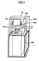
Fig. 1 is a perspective view showing an appearance of an automated transaction machine; -
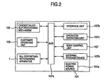
Fig. 2 is a block diagram illustrating control relationship in the automated transaction machine; -
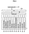
Fig. 3 is a block diagram illustrating control relationship in a bill depositing/withdrawing apparatus; -
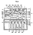
Fig. 4 is a schematic view of construction of a bill conveyance path; -
Fig. 5 is a side view of a cash slot mechanism at the time of feeding/stacking; -
Fig. 6 is a side view of the cash slot mechanism at the time of depositing/withdrawing; -
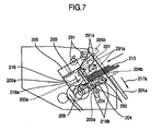
Fig. 7 is a side view of the cash slot mechanism at the time of depositing; -
Fig. 8 is a side view of the cash slot mechanism at the time of feeding; -
Fig. 9 is a side view of the cash slot mechanism at the time of stacking; -
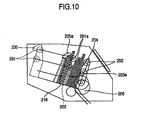
Fig. 10 is a side view of the cash slot mechanism at the time of discharging; -
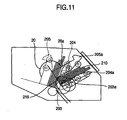
Fig. 11 is a side view of the cash slot mechanism at the time of discharging; -
Fig. 12 is a side view showing the cash slot mechanism at the time of discharging; -
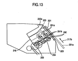
Fig. 13 is a side view of the cash slot mechanism at the time of recovery of a bill or bills as left; -
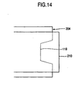
Fig. 14 is a plan view of a front plate of the cash slot mechanism; -
Fig. 15 is a flowchart at the time of selection of transaction; -
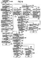
Fig. 16 is a flowchart of deposit transaction; -
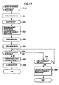
Fig. 17 is a flowchart of withdrawal transaction; -
Fig. 18 is a flowchart of recovery of a bill or bills as left; -
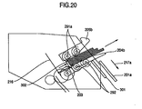
Fig. 19 is a side view of a cash slot mechanism according to another embodiment of the invention; and -
Fig. 20 is a side view of a cash slot mechanism according to another embodiment. - An embodiment of the invention will be described hereinafter with reference to the drawings.
-
Fig. 1 is a perspective view showing an appearance of anautomated transaction machine 101. - The
automated transaction machine 101 comprises ahousing 101b. Acustomer operating unit 105 is provided in an upper portion of thehousing 101b and a card/ detailedslip processing mechanism 102 is provided on the left. Thecustomer operating unit 105 displays and inputs contents of transaction. The card/detailedslip processing mechanism 102 is communicated with acard slot 102a provided on an upper,front plate 101 a to process a transaction card of a customer to print a detailed slip of transaction to discharge the same. - The upper,
front plate 101a of the automated transaction machine 101A is provided with a cash slot (bill slot) 21. A bill depositing/withdrawingapparatus 1 for processing bills is provided in theautomated transaction machine 101. - A bill storage section disposed below the bill depositing/withdrawing
apparatus 1 is enclosed by acashbox housing 106, which is separate from thehousing 101b and formed from an iron sheet having a thickness of several tens mm. While thehousing 101 b is also of a rigid housing structure, thecashbox housing 106 is further rigid in structure to increase security. Theautomated transaction machine 101 can process such transaction as depositing/withdrawing, transfer, etc. by a user with cards, bills, and detailed slips as media. -
Fig. 2 is a control block diagram showing control relationship in theautomated transaction machine 101. - The card/detailed
slip processing mechanism 102, the bill depositing/withdrawingapparatus 1, and thecustomer operating unit 105, which are accommodated in theautomated transaction machine 101, are connected to abody control unit 107 via abus 107a to perform necessary actions under the control of thebody control unit 107. Thebody control unit 107 is also connected to aninterface unit 107b, anoperator operating unit 107c, and an external storage device 107d as well as the elements described above via thebus 107a to give and take data as required, details of which are omitted because of not being directly related to a feature of the invention. In addition, thereference numeral 101 a shown inFig. 2 denotes an electric power source, which supplies electric power to the respective mechanisms and constituents described above. -
Fig. 3 is a control block diagram showing control relationship mainly in the bill depositing/withdrawingapparatus 1. - A
control unit 35 provided in the bill depositing/withdrawingapparatus 1 is connected to thebody control unit 107 of the machine through thebus 107a, and controls the bill depositing/withdrawingapparatus 1 in accordance with a command from thebody control unit 107 and detection of a state of the bill depositing/withdrawingapparatus 1, and transmits a state of the bill depositing/withdrawingapparatus 1 to thebody control unit 107 at need. The control unit is connected to drive motors, electromagnetic solenoids, and sensors for respective units (acash slot mechanism 20 as a bill storage section, abill discriminator 30, atemporary stacker 40, abill conveyance path 50, adeposit box 60, a retractbox 61, a non-genuinebill storing box 62, areject box 63, awithdrawal box 70, arecycle box 80, a load/collect box 81), and drives and controls actuators according to a transaction while monitoring a state thereof by means of sensors. -
Fig. 4 is a view of the construction of the bill depositing/withdrawingapparatus 1. - The bill depositing/withdrawing apparatus 1 comprises the cash slot mechanism 20, through which a user put-in/takes-out a bill or bills, the bill discriminator 30 for discrimination of a bill, the temporary stacker 40 for temporarily storing a bill or bills as put-in until the transaction is approved, one deposit box 60 for storing a bill or bills, for which transaction is approved, one retract box 61 for recovery of a bill or bills left by a user at the time of deposit and/or at the time of withdrawal, one non-genuine bill storing box 62 for storing a bill or bills as discriminated to be non-genuine, one reject box 63 for storing a bill or bills, which are inappropriate for withdrawal, one withdrawal box 70 for storing a bill or bills for withdrawal, two recycle boxes 80 serving as deposit and withdrawal, the load/collect box 81 for storing a bill or bills supplied to the recycle boxes 80 and a bill or bills recovered from the recycle boxes, the bill conveyance path 50, through which a bill or bills are conveyed via the bill discriminator 30 to the cash slot mechanism 20, the temporary stacker 40, the deposit box 60, the retract box 61, the non-genuine bill storing box 62, the reject box 63, the withdrawal box 70, the recycle boxes 80 and the load/collect box 81, and a control unit (not shown).
- Also, the bill depositing/withdrawing
apparatus 1 is composed of anupper conveyance mechanism 1a, which comprises thecash slot mechanism 20, thebill discriminator 30, thetemporary stacker 40, the retractbox 61, the non-genuinebill storing box 62, the load/collectbox 81 and thebill conveyance path 50, and alower conveyance mechanism 1b, which comprises thedeposit box 60, thereject box 63, thewithdrawal box 70, therecycle boxes 80, and a conveyance path 90 arranged on upper surfaces of the respective storage boxes to enable opening and closing. Further, thelower conveyance mechanism 1b is mounted in thecashbox housing 106, which is formed from an iron sheet having a thickness of about 50 mm, and a conveyance path between theupper conveyance mechanism 1 a and thelower conveyance mechanism 1b is interconnected by connectingconveyance paths - The connecting
conveyance path 501 h is provided in a position to be connected to aconveyance path 501 g of theupper conveyance mechanism 1 a on the upper surface of thecashbox housing 106, which encloses thelower conveyance mechanism 1b, and the connectingconveyance path 501i is provided in a position to be connected to aconveyance path 901 a of thelower conveyance mechanism 1b, and the connectingconveyance path 501h and the connectingconveyance path 501i are provided in a position to be connected to each other. A slit formed on the upper surface iron sheet of thecashbox housing 106 has a length for passage of a bill and a width corresponding to a width of rollers mounted so as to interpose a bill conveyed to the slit to discharge the same. In case of adopting a construction, in which thelower conveyance mechanism 1b is not enclosed by thecashbox housing 106, the slit is not necessarily needed provided that theupper conveyance mechanism 1a is placed directly on thelower conveyance mechanism 1b. While drive sources (motors) for the conveyance paths may be provided separately for the conveyance path of theupper conveyance mechanism 1a and for the conveyance path of thelower conveyance mechanism 1b, a single drive source may be used to transmit a driving force with gears provided among theconveyance paths 501 g-501h-501i-901a. - Also, the
bill conveyance path 50 passes through thebill discriminator 30 in dual directions to connect thecash slot mechanism 20, thetemporary stacker 40, thedeposit box 60, the retractbox 61, the non-genuinebill storing box 62, thereject box 63, thewithdrawal box 70, therecycle boxes 80 and the load/collectbox 81 via the conveyance paths indicated byarrows 501a to 501q and 901a to 901e. One-direction arrows out of the respective arrows denote one-direction bill conveyance paths, through which a bill or bills are conveyed in directions of associated arrows, and dual-direction arrows denote dual-direction conveyance paths, through which a bill or bills are switched over to either of associated dual directions every action of transaction. - The
bill conveyance path 50 is driven by drive motors (not shown) to switch a direction of rotation of an associated motor every action of transaction. Further,switchover gates switchover gates 902 are provided at branch points of thebill conveyance path 50 to switch bill conveyance directions as indicated by characters a, b every action of transaction. - The bill depositing/withdrawing
apparatus 1 constructed in the manner described above permits actions of deposit and withdrawal by a user, load/collect actions by a person in charge, and an action of automatic recovery of a bill or bills left by a user. - In an operation of deposit, the bill depositing/withdrawing
apparatus 1 separates bills put into thecash slot mechanism 20 one by one, and a kind of and truth or falsehood of a bill is discriminated in thebill discriminator 30. When discrimination is enabled, theswitchover gate 503 is switched over to aposition 503a and a bill is once stored in thetemporary stacker 40. When discrimination is not enabled in thebill discriminator 30 and when inclination is abnormal and an interval between bills is abnormal, an associated bill is not taken as a bill, deposit of which is rejected, into thetemporary stacker 40 but is stored in thecash slot mechanism 20 with theswitchover gate 503 switched over to anotherposition 503b and returned to a user. - When transaction is settled, the bill or bills stored in the
temporary stacker 40 are forwarded in a reverse order to that at the time of storage and caused to pass thebill discriminator 30 to be stored in an appointed storage box in a state, in which theswitchover gate 502 is switched over to a direction indicated by 502b and the switchover gate 903 for one of thedeposit box 60, therecycle boxes 80 and thereject box 63 is switched over to a direction indicated by 903b, thus terminating an action of deposit. - At the time of withdrawal transaction, the bill depositing/withdrawing
apparatus 1 discharges a predetermined number of bills from respective ones of thewithdrawal boxes 70 and therecycle boxes 80 every kind of bill and causes thebill discriminator 30 to discriminate a kind of each bill to branch the bills at theswitchover gate 503 to store the same in thecash slot mechanism 20 to pay the same to a user. At the time of the withdrawal, it is possible to bring about a state, in which a bill or bills project toward a user from the upper,front plate 101 a of theautomated transaction machine 101 as described later. - Also, the bill depositing/withdrawing
apparatus 1 enables loading and collecting actions between the load/collectbox 81 and therecycle boxes 80 via thebill discriminator 30. The loading action is one, in which a bill or bills being desired to be set every kind are not individually set in therecycle boxes 80 but are set in a lump in the load/collectbox 81 by a person in charge and automatically stored in therecycle boxes 80 within the apparatus. The recovering action is one, in which a person in charge does not individually draw out a bill or bills from the respective recycle boxes when therecycle boxes 80 become full, or the like but a predetermined number of bills are automatically collected and stored in the load/collectbox 81 from therecycle boxes 80. The collecting action is one, in which a bill or bills are moved in a reverse route to that in the loading action and so details thereof are omitted. - Also, in the case where a user leaves a bill or bills in the
cash slot mechanism 20 at the time of deposit transaction and/or at the time of withdrawal transaction, the bill depositing/withdrawingapparatus 1 enables automatically collecting the bill or bills as left. The left bill collecting action is one, in which a bill or bills left in thecash slot mechanism 20 are stored in a lump in the retractbox 61. - Subsequently, the construction of the
cash slot mechanism 20, which constitutes a main part of the invention, will be described with reference to a configuration of thecash slot mechanism 20 shown inFigs. 5 to 14 . - As shown in
Fig. 5 , thecash slot mechanism 20 is provided inside thecash slot 21 on the upper,front plate 101 a provided obliquely on an upper portion of theautomated transaction machine 101. Thecash slot 21 is provided with anopening 20a. Thecash slot mechanism 20 is constructed so that a user can charge or take a bill or bills through theopening 20a in a depositing/withdrawingdirection 202. Ahousing shutter 201 is provided on theopening 20a to slide in an opening andclosing direction 217 perpendicular to the depositing/withdrawingdirection 202 to provide for opening and closing. - In addition, the
housing shutter 201 serves to prevent rain, dust, foreign matters, etc. from entering the machine but is dispensed with in the case where the machine is mounted indoor to be hard to be subjected to environmental influences. Also, when the machine is mounted in a location, which is considerably liable to be subjected to external, environmental influences, a double shutter structure will do, in which shutters are provided respectively on thehousing 101 b of theautomated transaction machine 101 and the bill depositing/withdrawingapparatus 1. - As shown in
Fig. 5 , with thecash slot mechanism 20, afront plate 204 arranged toward a user to constitute the front of theautomated transaction machine 101 when being in the feeding/stacking posture (the posture, in which bills 210 in a storage space A are inclined at around 75° ± 10° to the horizontal), a rear plate (moving plate) 205 arranged on an opposite side to the user, and anintermediate plate 203 arranged between thefront plate 204 and therear plate 205 are arranged in parallel to one another, and abill hopper 216 is provided to constitute a bottom plate perpendicular to these plates. A space surrounded by these plates forms the storage space A forbills 210. Thefront plate 204, therear plate 205 and theintermediate plate 203 are controlled by a drive motor (not shown) in moving in a mutually approaching direction and in a mutually distant direction (referred below to as direction of interposing movement). Also, a length of thefront plate 204 from a base thereof (a side, on which the front plate abuts against the bill hopper 216) to a tip end thereof and a length of therear plate 205 from a base thereof (a side, on which the rear plate abuts against the bill hopper 216) to a tip end thereof are substantially the same as each other, and a length of theintermediate plate 203 from a base thereof (a side, on which the intermediate plate abuts against the bill hopper 216) to a tip end thereof is half the former length. In addition, a length of theintermediate plate 203 is not limited to this but may be set to an appropriate length. - Further, as shown in
Fig. 5 , a separation mechanism composed of afeed roller 206 and agate roller 207, which serve as bill feeding means, is arranged below the storage space A toward a user. Therefore, abill 210 charged into the storage space A is fed into the apparatus owing to a rotary action of thefeed roller 206, and thegate roller 207, which does not rotate in a direction of discharge, prevents two bills from being fed at a time. Thus, thebills 210 in thecash slot mechanism 20 are fed in a direction indicated by anarrow 208 to merge into a main bill conveyance path 501 (Fig. 4 ) via a depositunit conveyance path 251 a to be taken into the apparatus. In addition, thefeed roller 206 comprises a plurality of rollers having a considerably smaller width than that of thefront plate 204 and arranged so as to partially project into the storage space A from slits of thefront plate 204, which are provided in a comb-shaped manner. - Also, a cash slot
mechanism rotating motor 222 serving as posture changing means rotates thecash slot mechanism 20 to a position, in which respective tip ends of therear plate 205 and thefront plate 204 approach upper and lower ends of theopening 20a, with a center of rotation of thefeed roller 206 as a point of rotation as shown inFig. 6. Fig. 6 shows a state, in which the depositing/withdrawing posture (the posture, in which thebills 210 in the storage space A are inclined at around 25° ± 10° to the horizontal) is assumed upon rotation, and in this state, theopening 20a and the storage space A are communicated to each other. Accordingly, it is possible to discharge a bill or bills in the storage space A to a user and to allow a user to charge a bill or bills into the storage space A. Here, bills are inclined at around 25° ± 10° to the horizontal in the depositing/ withdrawing posture whereby bills are heightened in visibility for a user and bills as charged are heightened in quality of alignment. - A bill discharge mechanism discharges a bill or bills to a user. The bill discharge mechanism comprises a bundle conveyance mechanism (clamping means), which conveys bills in a bundle, and a pressure applying mechanism, which applies pressure to bills appropriately according to the number of bills.
- The bundle conveyance mechanism comprises
upper rollers 291 andlower rollers 292, which serve as drive rollers, and a drive unit (not shown). Theupper rollers 291 are arranged in a manner to overlap therear plate 205, slidingly move independently of therear plate 205 relative to thecash slot mechanism 20 in the same direction as a clamping movement direction of therear plate 205, and rotate in any position, to which the upper rollers slidingly moved. Thelower rollers 292 are arranged in a manner to overlap thefront plate 204, are fixed to thecash slot mechanism 20 and rotate at there. - The pressure applying mechanism comprises the
upper rollers 291 and thelower rollers 292, which constitute the bundle conveyance mechanism, thefront plate 204, therear plate 205, and a drive unit (not shown). - When a bill or bills are to be discharged to a user, the drive unit (not shown) of the pressure applying mechanism moves the
upper rollers 291 in the clamping movement direction to shift the same to a position, in which the upper rollers push down a surface of a bill, that is, a position indicated by 291a inFig. 6 . Thereby, theupper rollers 291 and thelower rollers 292 opposed to theupper rollers 291 cramps bills to apply pressure to the same appropriately according to the number of bills. In a state, in which pressure is applied on the bills in this manner, theupper rollers 291 and thelower rollers 292 are rotated by the drive unit (not shown) of the bundle conveyance mechanism to convey bills in bundle toward a user. At this time, bills are fed so that tip ends of a bundle of the bills project toward a user beyond the upper,front plate 101a. - That is, the
cash slot mechanism 20 permits a user to operate at a rotating angle of the depositing/withdrawing posture shown inFig. 6 , and discharges bills in the storage space A into the apparatus in the feeding/stacking posture shown inFig. 7 and performs operation to stack bills in the storage space A from within the apparatus. An explanation will be given according to transaction of deposit, withdrawal, and retract with reference toFigs. 7 to 13 . - At the time of deposit transaction, when a user charges a bill or bills as shown in
Fig. 7 , thehousing shutter 201 is moved to aposition 201a in a direction of anarrow 217a to provide for full opening so thatbills 210 are charged between thefront plate 204 and the intermediate plate 203 (theintermediate plate 203 is close to the rear plate 205), which are supported in thebill hopper 216. At this time, thefront plate 204 and therear plate 205 are caused to project toward a user beyond the upper,front plate 101 a and moved to positions indicated by 204b and 205b in the drawing in a direction of projection in parallel to a depositing/withdrawingdirection 202. - In addition, a
support plate 209 serving as a stopper is preferably provided around an intermediate position between a bottom of thebill hopper 216 and tip ends of thefront plate 204 and therear plate 205. Thesupport plate 209 can bear end surfaces of bills as charged. Preferably, thesupport plate 209 is structured to slidingly move as indicated by 209a inFig. 7 in the clamping movement direction or to slidingly move in the depositing/withdrawing direction 202 (seeFig. 5 ). - Thereby, it is possible to bear end surfaces of bills when bills are charged and to retreat the
support plate 209 on other occasions. In particular, thesupport plate 209 bears end surfaces of bills when the bills are charged whereby a user does not need to insert a hand to within the apparatus but can charge bills outside the apparatus. - Also, with a construction, in which sliding movement is made in the depositing/ withdrawing
direction 202, thesupport plate 209 can push out bills in the depositing/ withdrawingdirection 202 when the bills are to be fed. Preferably, thesupport plate 209 is mounted not to thecash slot mechanism 20 but to the housing of the bill depositing/ withdrawingapparatus 1, or a non-moving part except thecash slot mechanism 20 of the bill depositing/withdrawingapparatus 1. Thereby, it is possible to make use of thesupport plate 209 independently of the rotating action of thecash slot mechanism 20, thus enabling making the apparatus simple in construction. - When bills are charged as shown in
Fig. 7 , therear plate 205, theintermediate plate 203 and theupper rollers 291 are moved topositions arrow 218a to clamp the bills, and thesupport plate 209 is moved to aposition 209a shown in the drawing and outside the cash slot mechanism to rotate theupper rollers 291 and thelower rollers 292, respectively, in directions (opposite directions to directions of projection) of taking-in indicated by 219a, 219b. Also, thefront plate 204 and therear plate 205 are slidingly moved in the directions of taking-in to be stored in the apparatus. - In addition, a charging detection sensor 224 (
Fig. 7 ) may be provided in the vicinity of thesupport plate 209 in the storage space A so that operation, in which therear plate 205, theintermediate plate 203 and theupper rollers 291 are moved in the clamping direction, is performed after the chargingdetection sensor 224 detects charging of a bill or bills. In this case, since the clamping operation can be performed after it is confirmed that a bill or bills are surely charged to a position of thesupport plate 209, it is possible to prevent jam in conveyance from being caused due to incomplete charging and the bill depositing/withdrawingapparatus 1 from becoming down correspondingly. - Also, when clamping a bill or bills, pulse counts of motors (excess charging detection means) for moving the
rear plate 205, theintermediate plate 203, theupper rollers 291, etc. may be acquired and when the pulse counts are less than a reference value, bills may be determined to be packed excessively and an error message may be displayed on thecustomer operating unit 105 to provide for returning bills. Thereby, it is possible to prevent jam in conveyance from being caused due to excessive packing of bills. - Subsequently, as shown in
Fig. 8 , at the time of feeding operation of the charged bill or bills, thehousing shutter 201 is moved in a direction of anarrow 217b to provide for closing. Here, an inlet sensor 223 (seeFig. 13 ) functioning as a hand detection sensor for detecting a user's hand may be provided so that thehousing shutter 201 is closed after it is confirmed that a user separates a hand from the bill or bills. Thereby, it is possible to prevent thehousing shutter 201 from being closed in a state, in which a user's hand is present. Also, in order to urge a user to separate a hand from a bill or bills, an operation, in which the bundle conveyance mechanism takes in a bill or bills a little in a direction of retreat to stop, may be repeated after therear plate 205, theintermediate plate 203 and theupper rollers 291 are moved in the clamping direction to clamp a bill or bills, whereby a bill or bills are intermittently taken in. At this time, the bundle conveyance mechanism functions as an intermittent moving means. Thereby, a user enables use in a psychological sense of security without being given a fear that a bill or bills are suddenly taken in and a hand carrying the bill or bills is pulled into the apparatus. - After the
cash slot mechanism 20 is turned and moved at an angle of the feeding/ stacking posture shown inFig. 8 , theintermediate plate 203 is moved toward thefeed roller 206 to push a bill or bills to turn thefront plate 204a a little so that a base side of thefront plate 204a is moved toward thefeed roller 206. Also, thelower rollers 292 are moved so that thelower rollers 292 are positioned as a whole on a side over the surface of thefront plate 204 as viewed from a bill or bills. Thereby, theintermediate plate 203a can push a bill or bills toward thefeed roller 206, the rotating action of thefeed roller 206 feeds the bill or bills, and thegate roller 207, which does not rotate in the feeding direction, prevents two bills from being fed at a time. Thus, abill 210 in thecash slot mechanism 20 is fed in the direction indicated by anarrow 208 to merge into thebill conveyance path 50 to be taken into the apparatus. - Also, the
rear plate 205 is retreated to theposition 205a and a bill or bills, which thebill discriminator 30 cannot discriminate at the time of deposit operation, and a bill or bills, of which deposit is rejected due to inclination and an abnormal interval between bills, are conveyed from within the apparatus to be collected between therear plate 205a and theintermediate plate 203a. The bill or bills, of which deposit is rejected, are clamped between therear plate 205 and thefront plate 204 in the same manner as at the time of charging, thecash slot mechanism 20 is turned to the depositing/withdrawing posture, and theupper rollers 291 and thelower rollers 292, respectively, shown inFig. 7 are rotated in reverse directions to directions of thearrows 219a, 219b to return the bill or bills in a bundle to a user. At this time, therear plate 205 and thefront plate 204 may be pushed outside the upper,front plate 101 a through thecash slot 21 in the same manner as a bill or bills. As shown in a plan view ofFig. 14 , thefront plate 204 is formed centrally of a tip end thereof with arecess 119 as viewed from above, therecess 119 enabling a user to grasp a bill or bills directly. Also, therear plate 205 and thefront plate 204 clamp a returning bill or bills from above and under whereby a user is liable to pull out the bill or bills. - As shown in
Fig. 9 , at the time of money withdrawal transaction, a bill or bills being paid are conveyed in a direction of an arrow 5011 (seeFigs. 4 and9 ) to pass between guides (not shown) while being exerted by a force of frictional resistance and stacked in a space between theintermediate plate 203a and therear plate 205a. - Subsequently, as shown in
Fig. 10 , a drive unit (not shown) moves theintermediate plate 203 and therear plate 205, respectively, to thepositions Fig. 9 to cause theintermediate plate 203a, thefront plate 204, and therear plate 205a to clamp a bill or bills stored in thecash slot mechanism 20. After the bill or bills are clamped, thecash slot mechanism 20 is turned and moved to the money depositing/withdrawing posture as shown inFig. 11 . - After the
cash slot mechanism 20 is turned, the drive unit (not shown) of the pressure applying mechanism moves theupper rollers 291 to a position, in which a bill or bills are pushed down, that is, theposition 291 a shown inFig. 12 to cause thelower rollers 292 and theupper rollers 291 a to clamp the bill or bills. In addition, theupper rollers 291 may be moved to clamp a bill or bills before the cash slot mechanism is turned and moved. - After the bill or bills are clamped, the
housing shutter 201 is moved in the direction of thearrow 217a as shown inFig. 12 to open the shutter. After the shutter is opened, the drive unit (not shown) of the bundle conveyance mechanism rotates theupper rollers 291 a and thelower rollers 292 to discharge the bill or bills to a user through thecash slot 21. At this time, the bill or bills are conveyed to a position, in which the bill or bills project toward a user from the upper,front plate 101 a. - Also, the
rear plate 205 and thefront plate 204 are moved toward a user from the upper,front plate 101a, that is, to thepositions Fig. 12 through thecash slot 21. Thereby, a user can take out a bill or bills easily without looking into thecash slot 21. - Also, after the
rear plate 205 and thefront plate 204 are caused to project, thesupport plate 209 supports an end of a bill or ends of bills inside the apparatus as shown inFig. 7 . Thereby, a bill or bills are prevented from being erroneously pushed deep into the storage space A. Also, since a user cannot pull out a bill or bills while the bill or bills are pushed by therear plate 205 and thefront plate 204, thesupport plate 209 supports the bill or bills and then therear plate 205 is moved upward to release the push. While the rollers are not moved but remain in the position of clamping, excitation of the drive unit (not shown) is cancelled. Thereby, a bill or bills are clamped with an appropriate force whereby a user is made liable to pull out the bill or bills. - Further, after the
inlet sensor 223 functioning as a pulling-out detection sensor detects that a user has pulled out the bill or bills, therear plate 205 is moved to theposition 205a to enlarge a space in thecash slot mechanism 20 to facilitate visual confirmation by a user even if conveyance in a bundle is not successfully made and a bill or bills, conveyance of which fails, remain in the cash slot. - In addition, a discharge position, to which a bill or bills are fed, may be fixed irrespective of sizes of a bill or bills as fed, or may be regulated according to a length or lengths of a bill or bills measured by a sensor, which is provided in the bill depositing/ withdrawing apparatus to measure a length of a bill. Also, the discharge position may be regulated according to results of discrimination by the
bill discriminator 30 at the time of money withdrawal. - If a user leaves a bill or bills at the time of money deposit or at the time of money withdrawal, the bill or bills as left are automatically recovered. At the time of recovery of a left bill or bills, in the case where a left bill or bills remain on the
inlet sensor 223 as shown inFig. 13 , theupper rollers 291 are moved from theposition 291 a to a position on abill surface 291 b to clamp the bill or bills between it and thelower rollers 292, and theupper rollers 291 and thelower rollers 292 are rotated in reverse directions to directions at the time of discharge to store the bill or bills in thecash slot mechanism 20. After it is confirmed that any bill does not remain on theinlet sensor 223, thehousing shutter 201 is moved in the direction of thearrow 217b and the shutter is closed. Also, a sensor (not shown) in the cash slot mechanism can readily detect a bill or bills possibly remaining on other parts. - After the
housing shutter 201 is closed, thecash slot mechanism 20 is turned and moved from a position for the money depositing/withdrawing posture shown inFig. 11 to a position for the feeding/stacking posture shown inFig. 13 . After the cash slot mechanism is turned and moved, a bill is fed by the rotating action of thefeed roller 206 in the same manner as at the time of money deposit transaction and thegate roller 207, which does not rotate in the direction of discharge, prevents two bills from being fed at a time. Thus, a bill orbills 210 in thecash slot mechanism 20 are fed in the direction of thearrow 208 to merge into thebill conveyance path 50 to be taken into the apparatus to be stored in the retractbox 61. - Subsequently, details of operation of the
cash slot mechanism 20 in the money depositing/withdrawing transaction and in recovery of a bill or bills as left in the automated transaction machine will be described in order according to control flowcharts inFigs. 15 to 18 . -
Fig. 15 shows a flowchart when a user begins transaction and selects transaction. - The
automated transaction machine 101 permits thecustomer operating unit 105 to display contents of transaction by way of guidance display (STEP S101). - When a user selects transaction (STEP S102), the
automated transaction machine 101 carries out a money deposit transaction when a money deposit transaction is selected (STEP S103) and carries out a money withdrawal transaction when a money withdrawal transaction is selected (STEP S104). -
Fig. 16 shows a flowchart for the money deposit transaction andFig. 17 shows a flowchart for the money withdrawal transaction. Processing in thick frames inFigs. 16 and17 are ones accompanied by moving action of thecash slot mechanism 20.Fig. 18 shows a flowchart for recovering or retracting a bill or bills as left. - As shown in
Fig. 16 , the bill depositing/withdrawingapparatus 1 for carrying out money deposit transaction displays guidance to show a limit of the number of received bills, etc. on the customer operating unit 105 (STEP S1). Subsequently, after thecash slot mechanism 20 is moved to the money depositing/withdrawing posture as shown inFig. 6 , a shutter opening processing is performed to open the housing shutter 201 (STEP S2), and a money deposit preparing processing is performed to cause thefront plate 204 and therear plate 205 to project toward a user through theopening 20a from the upper,front plate 101a (STEP S3) as shown inFig. 7 . The procedure is standby until a bill or bills being received are set in the cash slot mechanism 20 (STEP S4). - When a bill or bills are charged into the
cash slot mechanism 20, thefront plate 204 and therear plate 205 are taken inside theopening 20a (STEP S5) and thehousing shutter 201 is closed in the shutter closing processing (STEP S6). - In a received money counting processing, in which a bill or bills as received are counted, the
cash slot mechanism 20 is moved to the feeding/stacking posture shown inFig. 8 to perform actions of feeding and separating a bill or bills as received (STEP S7). - In the STEP S7, a bill or bills charged into the
cash slot mechanism 20 are separated one by one and conveyed to thebill discriminator 30 to be subjected to discrimination of truth or falsehood of a bill, and a bill or bills, which are discriminated in thebill discriminator 30 to afford deposit, are once stored in thetemporary stacker 40. - At this time, except a normal action, in which a bill or bills as received are all discriminated to afford deposit and are once stored in the
temporary stacker 40, there are a case where discrimination is not possible in thebill discriminator 30 or inclination and an abnormal interval between bills causes rejection of deposit, and a bill or bills, deposit of which is rejected, are stored in thecash slot mechanism 20, and a case where detection of an abnormal bill or bills in separation of a bill or bills as received leads to abnormal stoppage in the course of counting of a bill or bills as received while a bill or bills as received are left in thecash slot mechanism 20. - When abnormal stoppage is caused in the course of counting of a bill or bills as received, presence of rejection of money deposit is discriminated and when rejection of money deposit is present (STEP S14: Y), a guidance is displayed (STEP S19) and a bill or bills, deposit of which is rejected, and an abnormal bill or bills are returned from the cash slot mechanism 20 (STEP S20). At this time, the
cash slot mechanism 20 is changed to the money depositing/withdrawing posture from the feeding/stacking posture under a state, in which a bill or bills, deposit of which is rejected, and an abnormal bill or bills are stored in the storage space A of thecash slot mechanism 20. - When rejection of money deposit is absent in the STEP S14 (STEP S14: N), a guidance is displayed (STEP S17) and an abnormal bill or bills are returned from the cash slot mechanism 20 (STEP S18). At this time, the
cash slot mechanism 20 is changed to the money depositing/withdrawing posture from the feeding/stacking posture under a state, in which an abnormal bill or bills are stored in the storage space A of thecash slot mechanism 20. - In the case where abnormal stoppage is not caused in the course of counting of a bill or bills as received in the STEP S8 (STEP S8: N) and rejection of money deposit is present (STEP S9: Y), a guidance is displayed (STEP S15) and a bill or bills, deposit of which is rejected, are returned from the cash slot mechanism 20 (STEP S16). At this time, the
cash slot mechanism 20 is changed to the money depositing/withdrawing posture from the feeding/stacking posture under a state, in which a bill or bills, deposit of which is rejected, are stored in the storage space A of thecash slot mechanism 20. - In this manner, after the
cash slot mechanism 20 is changed to the money depositing/withdrawing posture, thehousing shutter 201 is opened in the shutter opening processing (STEP S21), thefront plate 204 and therear plate 205 are caused to project toward a user through theopening 20a from the upper,front plate 101 a (STEP S22), and it is confirmed that a bill or bills are pulled out (STEP S23). - After it is confirmed that a bill or bills are pulled out (STEP S23: Y), the bill depositing/withdrawing
apparatus 1 takes thefront plate 204 and therear plate 205 into the apparatus (STEP S24) and performs the shutter closing processing (STEP S25) to return a bill or bills, deposit of which is rejected, to a user. - After a bill or bills, deposit of which is rejected, and the like are returned, the procedure returns to a guidance processing in STEP S1 in case of accepting the received money counting processing again (STEP S26: Y), and the procedure proceeds to the guidance processing in STEP S10 in case of not accepting the received money counting processing (STEP S26: N).
- In the case where pulling-out is not detected in the STEP S23 (STEP S23: N) and a predetermined period of time elapses (STEP S27: Y), it is determined that a bill or bills are left and a retracting processing is performed in order to continue a subsequent transaction (STEP S28).
- In the case where an abnormal stoppage is not caused in the course of received money counting in the received money counting processing in STEP S7 (STEP S8: N) and rejection of money deposit is not generated (STEP S9: N), a guidance for the number of bills counted in the received money counting processing in STEP S7 is displayed on the customer operating unit 105 (STEP S10). When a user confirms (depress a confirmation button) an amount of money as received (STEP S11: Y), center communication is performed (STEP S12) and a money deposit transaction is settled to perform a received money storage processing (STEP S13), thus terminating the money deposit transaction. In the received money storage processing (STEP S13), the
bill discriminator 30 again discriminates information of a kind of a bill for a bill or bills in thetemporary stacker 40 and a processing is performed to store the bill or bills in either of themoney deposit box 60 and therecycle boxes 80. - In the case where a user does not confirm acknowledgement of an amount of money as received (STEP S11: N) but selects cancellation of money deposit (STEP S29: Y), a cancellation return processing, in which a bill or bills in the
temporary stacker 40 are stored in thecash slot mechanism 20, is performed (STEP S30). Thereafter, the shutter opening processing is performed (STEP S31) and the bill discharge processing is performed projecting thefront plate 204 and therear plate 205 toward a user through theopening 20a from the upper,front plate 101a (STEP S32). When it is confirmed that a bill or bills are pulled out (STEP S33: Y), thefront plate 204 and therear plate 205 are taken into the apparatus (STEP S34) and the shutter closing processing is performed (STEP S35) to complete returning a bill or bills as received to a user. - In the case where recharging is permitted (STEP S36: Y), the procedure returns to the guidance processing in STEP S1, and in the case where recharging is not permitted (STEP S36: N), the money deposit transaction is terminated.
- In the case where a user does not pull out a bill or bills for a predetermined period of time or longer in the STEP S33 (STEP S37: Y), it is determined that a bill or bills are left and the retract processing (STEP S38) is performed in order to continue a subsequent transaction.
-
Fig. 17 is a flowchart illustrating a money withdrawal transaction processing. The bill depositing/withdrawingapparatus 1, which carries out a money withdrawal transaction, instructs a user to input a password, an amount of money being paid, etc. by way of guidance display (STEP S51) and receives, through center communication, instructions to carry out a transaction of contents as input (STEP S52), thus starting the money withdrawal processing (STEP S53).
In the money withdrawal processing, a kind of a bill for a bill or bills fed a predetermined number by a predetermined number from themoney withdrawal boxes 70 and therecycle boxes 80 is discriminated every kind of bill by thebill discriminator 30 and the bill or bills are stored in a bundle in the storage space A, which assumes the feeding/stacking posture (Fig. 9 ). Under a state, in which a bill or bills as paid are stored in the storage space A, the bill depositing/withdrawingapparatus 1 changes thecash slot mechanism 20 to the money depositing/withdrawing posture from the feeding/stacking posture (Figs. 10 and11 ). - The bill depositing/withdrawing
apparatus 1 performs the shutter opening processing (STEP S54) and has the bundle conveyance mechanism feed a bill or bills to a user (STEP S55) as shown inFig. 12 . At this time, thefront plate 204 and therear plate 205 are caused to project toward a user through theopening 20a from the upper,front plate 101 a and excitation of driving means (for example, a solenoid) is made OFF to facilitate pulling out a bill or bills. - When pulling out a bill or bills is detected (STEP S56: Y), the bill depositing/withdrawing
apparatus 1 takes thefront plate 204 and therear plate 205 into the upper,front plate 101 a (STEP S57) and performs the shutter closing processing (STEP S58). - In the case where a user does not pull out a bill or bills for a predetermined period of time or longer (STEP S56: N, STEP S59: Y), it is determined that a bill or bills are left and the retract processing (STEP S60) described with reference to
Fig. 18 is performed in order to store the left bill or bills in a bundle in the retractbox 61 and continue a subsequent transaction. -
Fig. 18 is a flowchart illustrating the retract processing. - In the case where a user does not pull out a bill or bills for a predetermined period of time or longer in returning a bill or bills, deposit of which is rejected, canceling and returning, leaving a bill or bills being paid, or the like, it is determined that a bill or bills are left and the retract processing is performed in order to continue a subsequent transaction.
- Here, when it is detected that a bill or bills are left, the
front plate 204 is vibrated and moved a little. - Since a bill or bills as left move a little due to the vibration of the
front plate 204, detection by the sensor can be made sure. Thereby, an erroneous detection is prevented, in which a bill or bills are not detected by the sensor although a bill or bills are left. - The bill depositing/withdrawing
apparatus 1 takes thefront plate 204 and therear plate 205 into the apparatus whereby a bill or bills, which are fed but not pulled out, are stored in the cash slot mechanism 20 (STEP S61). When taking-in of a bill or bills is completed (STEP S62: Y), the bill depositing/withdrawingapparatus 1 performs the shutter closing processing (STEP S63). After the shutter closing processing, the bill depositing/withdrawingapparatus 1 changes the posture of thecash slot mechanism 20 to the feeding/stacking posture (STEP S64) to discharge a bill or bills from thecash slot mechanism 20 to store the same in the retractbox 61. - According to the embodiment described above, when a bill or bills are charged, a user can perform an operation of money deposit without feeling a fear in inserting a hand into the
cash slot 21 having a drive unit. That is, since it suffices to charge a bill or bills between thefront plate 204 and therear plate 205, which project toward a user from thecash slot 21, a user's psychological sense is not a sense of inserting a hand into the apparatus but a sense of charging a bill or bills into a slot outside the apparatus. Therefore, a user can perform an operation of charging a bill or bills feeling psychologically at rest without a psychological feeling of fear. - Also, a user making use of a wheelchair does not need inserting a hand deep into the cash slot but suffices to charge a bill or bills between the
front plate 204 and therear plate 205, which project, so that a distance to a position of money deposit becomes small, thus enabling an improvement in operability. - Also, in case of foreign bills, which are considerably different in size every kind of bill, bills are unevenly aligned in some cases when they are charged in a laid posture, the invention enables a change of posture to the feeding/stacking posture to turn and move a bill or bills, which are charged in a laid posture into the
cash slot mechanism 20 in a money depositing/withdrawing posture, thus enabling the bill or bills to be changed to an upright posture. Thereby, uneven alignment of ends of bills is corrected owing to the effect of gravity, thus enabling decreasing an abnormality in conveyance, such as jam of bills, etc. Besides, a simple construction can be realized at low cost by making use of gravity in correction of uneven alignment. - Also, when a bill or bills are to be fed, it is possible to clamp the bill or bills to discharge the same in a bundle to a user. At this time, the bill or bills are pushed out toward a user from the front of the
housing 101b. Thereby, in that operation, in which a user receives a bill or bills, there is produced the same effect as at the time of charging that a psychological feeling of fear is absent and even a user making use of a wheelchair can receive a bill or bills easily. - Also, since a bill or bills are clamped between the
front plate 204 and therear plate 205 at the time of bill discharge, a bill or bills are not scattered even in the case where the apparatus is mounted outdoor and a strong wind blows, thus enabling surely delivering a bill or bills to a user. - Also, since the
front plate 204 supports a bottom of a bill or bottoms of bills at the time of bill discharge, thefront plate 204 serves as a saucer to make a user liable to receive a bill or bills. - Also, even if conveyance in a bundle is not successful and a bill or bills, conveyance of which fails, remain in the
cash slot 21, therear plate 205 as a push plate, which constitutes thecash slot mechanism 20, is moved to enlarge an interior of thecash slot mechanism 20 to make the storage space A easy to see, thus making a user liable to make visual confirmation to enable preventing a bill or bills from being left. - Also, in the case where a bill or bills as left are present, the sensor in the
cash slot 21 can readily detect the bill or bills as left, which can be retracted intact by the bundle conveyance mechanism. Thereby, it is possible for the apparatus to continue a subsequent transaction without becoming down. - In this manner, the bill depositing/withdrawing
apparatus 1 described above can realize a bill depositing/withdrawing apparatus, in which jam in conveyance and leaving a bill or bills are decreased and which has a user friendly money depositing/withdrawing interface and is high in reliability. - In addition, according to another embodiment, an
inner shutter 301 as an opening and closing shutter may be provided on thecash slot mechanism 20 as in a configuration of thecash slot mechanism 20 shown inFigs. 19 and20 . Theinner shutter 301 has a length from the tip end of thefront plate 204 to the tip end of therear plate 205, and slidingly moves in parallel to thehousing shutter 201 from a position, in which the opening of the storage space A is covered as shown inFig. 19 , to a position, in which the opening of the storage space A is opened as shown inFig. 20 . Also, theinner shutter 301 is mounted to thecash slot mechanism 20 to turn and move with thecash slot mechanism 20 when thecash slot mechanism 20 turns and moves changing in posture between the money depositing/withdrawing posture and the feeding/stacking posture. Theinner shutter 301 is structured to make an opening and closing action simultaneously with an opening and closing action of thehousing shutter 201. - Thereby, when the
cash slot mechanism 20 is changed in posture for the money deposit processing and the money withdrawal processing, theinner shutter 301 is put in a closed state, thus enabling preventing a centrifugal force in turning at the time of change in posture from causing a bill orbills 210 to spring from the storage space A and from unbalancing bills, which are unevenly set about the opening, to make the same scatter in the apparatus. - Also, when the
inner shutter 301 is not closed after a bill or bills are charged in the money deposit processing, it is preferable to open theinner shutter 301 and thehousing shutter 201 to return a bill or bills 210. At this time, preferably, thecustomer operating unit 105 or the like invites a user to align and recharge a bill or bills. Thereby, it is possible to prevent the money deposit processing from being carried out in a state, in which theinner shutter 301 is not fully closed. - Also, a
stopper 302 shown inFigs. 19 and20 may be provided on thecash slot mechanism 20 in place of the support plate 209 (seeFig. 7 ). Preferably, thestopper 302 is mounted to thecash slot mechanism 20 to function as a bottom plate in the innermost of the storage space A and to slidingly move toward this side (tip ends of thefront plate 204 and the rear plate 205) from the innermost of the storage space A (bases of thefront plate 204 and the rear plate 205). Preferably, the stopper slidingly moves interlocking with thefront plate 204 and therear plate 205 over the same distance as that of the latter. - Thereby, it is possible to surely push a bill or
bills 210 toward a user when the bill orbills 210 are to be fed in the money deposit processing, so that a user can take out the bill orbills 210 easily. Also, when charging of a bill or bills is permitted in the money deposit processing, thestopper 302 can prevent a bill orbills 210 from entering the innermost of the storage space A, so that a user enables use psychologically at rest without the need of inserting a hand into the apparatus. - Also, a structure may be employed that when the
inner shutter 301 is not closed at the time of bill charging, the closing action of theinner shutter 301 is retried performing an action, in which theinner shutter 301 is caused to swingably act to knock off a bill or bills inside and thestopper 302 and thefront plate 204 are moved to vibrate a bill or bills to make the same slide inside. Thereby, it is possible to restrict times of urging recharging in a state, in which theinner shutter 301 is not fully closed. - The invention is not limited to the construction of the embodiment described above but many embodiments are obtainable.
Claims (4)
- A bill depositing/withdrawing apparatus having a cash slot (21) for charging/ discharging a bill or bills, comprising:a bill storage section (20) provided inwardly of the cash slot (21) in the apparatus to store a bill or bills, andconveyance means (291, 292) for clamping the bill or bills stored or to be stored in the bill storage section (20) in a bill overlapping direction to convey the same,characterized in thatthe conveyance means (291, 292) is adapted to clamp the bill or bills at a position where the bill or bills project from the cash slot (21) to a user side, anda retreatable support plate (209) is provided for supporting end surfaces of the bill or bills located at said position.
- The apparatus of claim 1, wherein the conveyance means (291, 292) is adapted to convey a bill or bills between the position where the bill or bills project from the cash slot (21) to a user side and the bill storage section (20).
- The apparatus of claim 2, wherein the conveyance means (291, 292) is adapted to take in a bill or bills intermittently when conveying the bill or bills from the position where the bill or bills project from the cash slot (21) to a user side to the bill storage section (20).
- The apparatus of claim 1, further comprising a front plate (204) and a rear plate (205) for clamping a bill or bills together with the conveyance means (291, 292), the front plate (204) and the rear plate (205) being projectable from the cash slot (21) toward a user side.
Applications Claiming Priority (3)
| Application Number | Priority Date | Filing Date | Title |
|---|---|---|---|
| JP2006316748A JP4889456B2 (en) | 2006-11-24 | 2006-11-24 | Bill deposit / withdrawal apparatus and bill deposit / withdrawal apparatus control method |
| EP09009841A EP2116980B1 (en) | 2006-11-24 | 2007-11-20 | Method of controlling a bill depositing/ withdrawing apparatus |
| EP07022493A EP1926057B1 (en) | 2006-11-24 | 2007-11-20 | Bill depositing/withdrawing apparatus and method of controlling the same |
Related Parent Applications (3)
| Application Number | Title | Priority Date | Filing Date |
|---|---|---|---|
| EP09009841 Previously-Filed-Application | 2007-11-20 | ||
| EP07022493.6 Division | 2007-11-20 | ||
| EP09009841.9 Division | 2009-07-29 |
Publications (2)
| Publication Number | Publication Date |
|---|---|
| EP2267668A1 EP2267668A1 (en) | 2010-12-29 |
| EP2267668B1 true EP2267668B1 (en) | 2012-02-01 |
Family
ID=39226801
Family Applications (5)
| Application Number | Title | Priority Date | Filing Date |
|---|---|---|---|
| EP10010105A Not-in-force EP2267667B1 (en) | 2006-11-24 | 2007-11-20 | Bill depositing/withdrawing apparatus |
| EP07022493A Not-in-force EP1926057B1 (en) | 2006-11-24 | 2007-11-20 | Bill depositing/withdrawing apparatus and method of controlling the same |
| EP10010106A Not-in-force EP2267668B1 (en) | 2006-11-24 | 2007-11-20 | Bill depositing/withdrawing apparatus |
| EP09009841A Not-in-force EP2116980B1 (en) | 2006-11-24 | 2007-11-20 | Method of controlling a bill depositing/ withdrawing apparatus |
| EP08014396A Active EP2017799B1 (en) | 2006-11-24 | 2007-11-20 | Bill depositing/withdrawing apparatus and automated transaction machine |
Family Applications Before (2)
| Application Number | Title | Priority Date | Filing Date |
|---|---|---|---|
| EP10010105A Not-in-force EP2267667B1 (en) | 2006-11-24 | 2007-11-20 | Bill depositing/withdrawing apparatus |
| EP07022493A Not-in-force EP1926057B1 (en) | 2006-11-24 | 2007-11-20 | Bill depositing/withdrawing apparatus and method of controlling the same |
Family Applications After (2)
| Application Number | Title | Priority Date | Filing Date |
|---|---|---|---|
| EP09009841A Not-in-force EP2116980B1 (en) | 2006-11-24 | 2007-11-20 | Method of controlling a bill depositing/ withdrawing apparatus |
| EP08014396A Active EP2017799B1 (en) | 2006-11-24 | 2007-11-20 | Bill depositing/withdrawing apparatus and automated transaction machine |
Country Status (8)
| Country | Link |
|---|---|
| US (1) | US7708192B2 (en) |
| EP (5) | EP2267667B1 (en) |
| JP (1) | JP4889456B2 (en) |
| KR (1) | KR20080047278A (en) |
| CN (2) | CN101916469B (en) |
| AT (5) | ATE544137T1 (en) |
| DE (3) | DE602007012150D1 (en) |
| TW (1) | TW200839655A (en) |
Families Citing this family (87)
| Publication number | Priority date | Publication date | Assignee | Title |
|---|---|---|---|---|
| JP4920697B2 (en) * | 2006-11-13 | 2012-04-18 | グローリー株式会社 | Banknote handling equipment |
| DE102007056998A1 (en) * | 2007-11-27 | 2009-05-28 | Giesecke & Devrient Gmbh | Device for accepting and dispensing banknotes |
| DE102008030878A1 (en) * | 2008-06-30 | 2009-12-31 | Giesecke & Devrient Gmbh | Apparatus and method for accepting or dispensing banknotes |
| DE102008052694A1 (en) * | 2008-10-22 | 2010-04-29 | Wincor Nixdorf International Gmbh | Device and method for separating banknotes of a value note stack |
| US8371451B2 (en) * | 2008-11-06 | 2013-02-12 | Glory Ltd. | Banknote handling apparatus |
| CN103646460A (en) * | 2008-12-09 | 2014-03-19 | 光荣株式会社 | Banknote depositing apparatus and banknote processing apparatus |
| JP5291723B2 (en) | 2008-12-09 | 2013-09-18 | グローリー株式会社 | Bill deposit processing apparatus and bill deposit processing method |
| JP5277018B2 (en) | 2009-02-17 | 2013-08-28 | ローレル精機株式会社 | Banknote handling machine |
| JP5274303B2 (en) * | 2009-02-25 | 2013-08-28 | 日立オムロンターミナルソリューションズ株式会社 | Paper sheet handling equipment |
| JP5329259B2 (en) * | 2009-02-25 | 2013-10-30 | 日立オムロンターミナルソリューションズ株式会社 | Paper sheet handling equipment |
| KR101095407B1 (en) * | 2009-02-25 | 2011-12-16 | 히타치 오므론 터미널 솔루션즈 가부시키가이샤 | Paper handling device, paper receiving method and paper discharging method |
| JP5308216B2 (en) * | 2009-04-06 | 2013-10-09 | 日立オムロンターミナルソリューションズ株式会社 | Paper sheet handling equipment |
| CN102396007A (en) * | 2009-04-16 | 2012-03-28 | 卡纳安·拉卡斯密纳拉扬 | Multi-functional integrated cam -gear- encoder |
| JP5274355B2 (en) * | 2009-04-23 | 2013-08-28 | 日立オムロンターミナルソリューションズ株式会社 | Paper sheet handling equipment |
| JP5286178B2 (en) * | 2009-07-10 | 2013-09-11 | 日立オムロンターミナルソリューションズ株式会社 | Paper sheet handling equipment, automatic transaction equipment |
| US20110016046A1 (en) * | 2009-07-17 | 2011-01-20 | Doug Lindstrom | Cash-deposit Device, Method, and System |
| JP5474492B2 (en) * | 2009-11-05 | 2014-04-16 | グローリー株式会社 | Banknote deposit device |
| JP5410932B2 (en) * | 2009-11-25 | 2014-02-05 | 日立オムロンターミナルソリューションズ株式会社 | Banknote handling equipment |
| JP5471366B2 (en) | 2009-11-30 | 2014-04-16 | 沖電気工業株式会社 | Media processing device |
| JP5462637B2 (en) * | 2010-01-05 | 2014-04-02 | 日立オムロンターミナルソリューションズ株式会社 | Paper sheet handling equipment |
| JP5377357B2 (en) * | 2010-02-19 | 2013-12-25 | 日立オムロンターミナルソリューションズ株式会社 | Paper sheet handling equipment |
| JP5518552B2 (en) * | 2010-04-13 | 2014-06-11 | ローレル精機株式会社 | Banknote handling equipment |
| US8262076B2 (en) * | 2010-07-08 | 2012-09-11 | Ncr Corporation | Media depository |
| JP5664355B2 (en) * | 2011-03-09 | 2015-02-04 | 沖電気工業株式会社 | Paper sheet processing apparatus and transaction apparatus |
| JP5457397B2 (en) * | 2011-05-26 | 2014-04-02 | 富士通フロンテック株式会社 | Banknote deposit and withdrawal device |
| JP5779433B2 (en) * | 2011-07-15 | 2015-09-16 | 日立オムロンターミナルソリューションズ株式会社 | Bill handling apparatus and bill deposit method using the same |
| CN102324138B (en) * | 2011-09-08 | 2013-11-06 | 广州广电运通金融电子股份有限公司 | Paper sheet stacking and recycling device and paper sheet processing equipment with same |
| CN104205177B (en) * | 2012-01-23 | 2017-04-12 | 日本金钱机械株式会社 | Document recycle box |
| JP5518923B2 (en) * | 2012-03-06 | 2014-06-11 | 東芝テック株式会社 | Banknote dispensing device |
| CN103310531B (en) * | 2012-03-13 | 2017-07-25 | 上海古鳌电子科技股份有限公司 | Cleaning-sorting machine automatic binding press-note mechanism |
| CN102682517B (en) * | 2012-05-10 | 2014-04-16 | 广州广电运通金融电子股份有限公司 | Device and method for ensuring safety of self-service end-user funds |
| JP5954037B2 (en) * | 2012-08-09 | 2016-07-20 | 沖電気工業株式会社 | Bill processing apparatus and bill processing method |
| JP5859945B2 (en) * | 2012-10-26 | 2016-02-16 | 日立オムロンターミナルソリューションズ株式会社 | Bill handling apparatus and bill detection method |
| KR101591826B1 (en) * | 2012-12-14 | 2016-02-18 | 노틸러스효성 주식회사 | Apparatus for receiving and dispensing bill and method for receiving and dispensing bill |
| KR101405082B1 (en) * | 2012-11-15 | 2014-06-10 | 노틸러스효성 주식회사 | Apparatus for receiving and dispensing bill and method for receiving and dispensing bill |
| US9240107B2 (en) | 2012-11-15 | 2016-01-19 | Nautilus Hyosung Inc. | Apparatus for receiving and dispensing bill and method for receiving and dispensing bill |
| US8899570B2 (en) * | 2012-12-27 | 2014-12-02 | Nautilus Hyosung Inc. | Moving rail assembly and apparatus for receiving and dispensing bill |
| KR102030513B1 (en) * | 2012-12-27 | 2019-11-18 | 효성티앤에스 주식회사 | Apparatus for receiving and dispensing |
| KR101405080B1 (en) | 2012-12-27 | 2014-06-13 | 노틸러스효성 주식회사 | Assembly for moving rail |
| US9643785B2 (en) * | 2013-01-29 | 2017-05-09 | Ncr Corporation | Bunch presentation |
| WO2014155645A1 (en) * | 2013-03-29 | 2014-10-02 | 日立オムロンターミナルソリューションズ株式会社 | Paper-handling device and automatic transaction device |
| CN103268666B (en) * | 2013-05-23 | 2015-07-22 | 广州广电运通金融电子股份有限公司 | Cash process equipment and cash temporary storage device thereof |
| CN103413376A (en) * | 2013-07-17 | 2013-11-27 | 深圳市怡化电脑有限公司 | ATM access unit and control method |
| US10504315B2 (en) | 2013-08-05 | 2019-12-10 | Ncr Corporation | Clamping of media items |
| GB2517983B (en) * | 2013-09-09 | 2016-03-16 | Ibm | Security apparatus for an automated teller machine |
| US9472041B2 (en) * | 2013-10-31 | 2016-10-18 | Ncr Corporation | Clamping of media items |
| JP6030537B2 (en) * | 2013-11-29 | 2016-11-24 | 日立オムロンターミナルソリューションズ株式会社 | Paper sheet handling equipment |
| KR101534412B1 (en) * | 2013-11-29 | 2015-07-07 | 노틸러스효성 주식회사 | Medium processing apparatus |
| JP6225770B2 (en) * | 2014-03-14 | 2017-11-08 | 沖電気工業株式会社 | Cash processing equipment |
| CN104008598A (en) * | 2014-05-04 | 2014-08-27 | 昆山古鳌电子机械有限公司 | Paper money inlet and outlet device and control method of paper money inlet and outlet device |
| CN103971466A (en) * | 2014-05-23 | 2014-08-06 | 昆山古鳌电子机械有限公司 | Paper money depositing and withdrawing mechanism and automatic cash transaction device |
| CN103971467A (en) * | 2014-05-23 | 2014-08-06 | 昆山古鳌电子机械有限公司 | Paper money inlet/outlet device and control method |
| CN104157074B (en) * | 2014-08-20 | 2016-09-28 | 广州广电运通金融电子股份有限公司 | Rotary banknote feeding apparatus |
| JP2016045593A (en) * | 2014-08-20 | 2016-04-04 | グローリー株式会社 | Paper processing apparatus |
| US9934642B2 (en) * | 2014-12-18 | 2018-04-03 | Crane Payment Innovations, Inc. | Multiclass logical document recycler management |
| JP6430301B2 (en) * | 2015-03-13 | 2018-11-28 | 日立オムロンターミナルソリューションズ株式会社 | Banknote handling equipment |
| CN105139512A (en) * | 2015-07-30 | 2015-12-09 | 恒银金融科技股份有限公司 | ATM pressure detection device and method |
| CN105118149A (en) * | 2015-08-19 | 2015-12-02 | 上海古鳌电子科技股份有限公司 | Sheet processing device and automated teller machine |
| JP2017058845A (en) * | 2015-09-15 | 2017-03-23 | グローリー株式会社 | Currency processing device and currency processing method |
| US9905084B2 (en) | 2015-10-12 | 2018-02-27 | Diebold Nixdorf, Incorporated | Automated transaction machine with articulated note acceptor-presenter |
| US9646465B2 (en) * | 2015-10-12 | 2017-05-09 | Diebold Self-Service Systems, Division Of Diebold, Incorporated | Automated teller machine with escrow |
| CN105502062B (en) * | 2016-01-06 | 2017-07-25 | 上海古鳌电子科技股份有限公司 | One kind presss from both sides paper money, deposits paper money device |
| GB2552026B (en) | 2016-07-08 | 2020-06-10 | Ibm | Shutter assembly for an automated teller machine |
| CN106251475B (en) * | 2016-07-27 | 2022-05-31 | 深圳怡化电脑股份有限公司 | Coin pressing device, paper money input and output device and automatic storage money machine |
| JP2018132872A (en) * | 2017-02-14 | 2018-08-23 | 沖電気工業株式会社 | Cash processing device |
| CN108537947B (en) * | 2017-03-02 | 2021-04-13 | 山东新北洋信息技术股份有限公司 | Access port device and teller machine |
| CN107424295A (en) * | 2017-08-22 | 2017-12-01 | 昆山古鳌电子机械有限公司 | A kind of bank note treatment device |
| CN107657716A (en) * | 2017-08-22 | 2018-02-02 | 昆山古鳌电子机械有限公司 | A kind of bank note treatment device |
| CN107424296A (en) * | 2017-08-22 | 2017-12-01 | 昆山古鳌电子机械有限公司 | A kind of bank note treatment device |
| US10249150B1 (en) | 2017-10-03 | 2019-04-02 | International Business Machines Corporation | Security apparatus for an automated teller machine |
| US10109160B1 (en) | 2017-10-03 | 2018-10-23 | International Business Machines Corporation | Shutter assembly for an automated teller machine |
| JP6978936B2 (en) * | 2017-12-28 | 2021-12-08 | 日立チャネルソリューションズ株式会社 | Banknote processing device |
| CN108334911A (en) * | 2018-03-01 | 2018-07-27 | 深圳怡化电脑股份有限公司 | Gate mechanism |
| CN108442843A (en) * | 2018-03-01 | 2018-08-24 | 深圳怡化电脑股份有限公司 | Gate finger pinch device and its gate finger method |
| KR102102278B1 (en) * | 2018-10-29 | 2020-04-21 | 효성티앤에스 주식회사 | A doposit/withdrawal apparatus of ATM and the control method thereof |
| CN109448223A (en) * | 2019-01-11 | 2019-03-08 | 上海古鳌电子科技股份有限公司 | A kind of the returned ticket channel design and its working method of billing machine |
| KR102165719B1 (en) * | 2019-04-10 | 2020-10-15 | 효성티앤에스 주식회사 | Automatic teller machine and method for separation of paper money thereof |
| RU2706955C1 (en) * | 2019-04-24 | 2019-11-21 | Общество С Ограниченной Ответственностью "Конструкторское Бюро "Дорс" (Ооо "Кб "Дорс") | Temporary accumulator and system for receiving banknotes |
| KR102214054B1 (en) * | 2019-09-11 | 2021-02-08 | 효성티앤에스 주식회사 | Device to prevent bills from flying for automated teller machine |
| DE102019125993A1 (en) * | 2019-09-26 | 2021-04-01 | Wincor Nixdorf International Gmbh | Device for handling notes of value |
| DE102019125995A1 (en) * | 2019-09-26 | 2021-04-01 | Wincor Nixdorf International Gmbh | Device for handling notes of value |
| JP7368183B2 (en) * | 2019-10-30 | 2023-10-24 | グローリー株式会社 | Money deposit/withdrawal device, money processing system, and money processing method |
| EP4109426A4 (en) * | 2020-02-21 | 2023-11-22 | Fujitsu Frontech Limited | Paper sheet handling device |
| KR102305823B1 (en) * | 2020-04-02 | 2021-09-30 | 주식회사 메카트로 | Banknote deposit apparatus and control method thereof |
| CN111710092B (en) * | 2020-08-18 | 2020-11-17 | 恒银金融科技股份有限公司 | Abnormal paper money transmission device |
| EP4296206A4 (en) | 2021-02-17 | 2024-04-03 | Fujitsu Frontech Ltd | Paper sheet handling device |
| AU2022320805A1 (en) * | 2021-07-28 | 2024-02-01 | Crane Payment Innovations, Inc. | Multi-mode bulk banknote feeder |
Family Cites Families (19)
| Publication number | Priority date | Publication date | Assignee | Title |
|---|---|---|---|---|
| JPS56136736A (en) * | 1980-03-28 | 1981-10-26 | Fujitsu Ltd | Feeder for paper or the like |
| JPS5714969A (en) * | 1980-06-30 | 1982-01-26 | Fujitsu Ltd | Bank note processor |
| JPS5960594A (en) * | 1982-09-29 | 1984-04-06 | 富士通株式会社 | Paper money handler |
| US4980543A (en) * | 1983-01-26 | 1990-12-25 | Tokyo Shibaura Denki Kabushiki Kaisha | Multiple denominator bank note depositor/dispenser with automatic loading to and from storage section |
| US5020787A (en) | 1988-05-06 | 1991-06-04 | Laurel Bank Machines Co., Ltd. | Bill processing apparatus |
| JP2667739B2 (en) * | 1990-08-16 | 1997-10-27 | 沖電気工業株式会社 | Banknote automatic deposit and withdrawal device |
| JPH09208134A (en) | 1996-02-01 | 1997-08-12 | Omron Corp | Bill processing device and transaction processing device |
| JP3286545B2 (en) | 1996-12-20 | 2002-05-27 | ローレルバンクマシン株式会社 | Banknote handling machine |
| US6398108B1 (en) * | 1997-12-20 | 2002-06-04 | Ncr Corporation | Machine for dispensing media |
| JP4135238B2 (en) * | 1998-12-08 | 2008-08-20 | 日立オムロンターミナルソリューションズ株式会社 | Banknote deposit and withdrawal machine |
| JP2000331214A (en) * | 1999-05-21 | 2000-11-30 | Hitachi Ltd | Paper sheet handling device and automatic transaction device |
| JP4815064B2 (en) * | 2001-05-07 | 2011-11-16 | マミヤ・オーピー株式会社 | Banknote deposit and withdrawal device |
| JP2003044897A (en) * | 2001-08-01 | 2003-02-14 | Hitachi Ltd | State detector for paper sheets and paper money handling device using this detector |
| JP4559697B2 (en) * | 2002-10-24 | 2010-10-13 | グローリー株式会社 | Circulating banknote deposit and withdrawal machine |
| WO2004059419A2 (en) * | 2002-12-16 | 2004-07-15 | Diebold, Incorporated | Automated banking machine currency dispenser modules |
| JP4408373B2 (en) * | 2004-01-23 | 2010-02-03 | 日立オムロンターミナルソリューションズ株式会社 | Banknote deposit and withdrawal device |
| JP4730946B2 (en) * | 2005-06-17 | 2011-07-20 | 株式会社ユニバーサルエンターテインメント | Banknote processing apparatus and control system for banknote processing apparatus |
| US7870997B2 (en) * | 2005-07-01 | 2011-01-18 | Diebold Self-Service Systems Division Of Diebold Incorporated | ATM that can center different sized cash stacks in a cash outlet opening |
| US7240829B2 (en) * | 2005-07-01 | 2007-07-10 | Diebold Self-Service Systems, A Division Of Diebold, Incorporated | ATM with stack transporter for bulk note deposit |
-
2006
- 2006-11-24 JP JP2006316748A patent/JP4889456B2/en not_active Expired - Fee Related
-
2007
- 2007-11-13 TW TW096142851A patent/TW200839655A/en not_active IP Right Cessation
- 2007-11-20 EP EP10010105A patent/EP2267667B1/en not_active Not-in-force
- 2007-11-20 DE DE602007012150T patent/DE602007012150D1/en active Active
- 2007-11-20 AT AT10010106T patent/ATE544137T1/en active
- 2007-11-20 AT AT10010105T patent/ATE544136T1/en active
- 2007-11-20 DE DE602007005905T patent/DE602007005905D1/en active Active
- 2007-11-20 EP EP07022493A patent/EP1926057B1/en not_active Not-in-force
- 2007-11-20 EP EP10010106A patent/EP2267668B1/en not_active Not-in-force
- 2007-11-20 EP EP09009841A patent/EP2116980B1/en not_active Not-in-force
- 2007-11-20 AT AT08014396T patent/ATE472146T1/en not_active IP Right Cessation
- 2007-11-20 DE DE602007007316T patent/DE602007007316D1/en active Active
- 2007-11-20 AT AT09009841T patent/ATE496355T1/en not_active IP Right Cessation
- 2007-11-20 AT AT07022493T patent/ATE464627T1/en not_active IP Right Cessation
- 2007-11-20 EP EP08014396A patent/EP2017799B1/en active Active
- 2007-11-21 US US11/943,642 patent/US7708192B2/en not_active Expired - Fee Related
- 2007-11-21 KR KR1020070119067A patent/KR20080047278A/en not_active Application Discontinuation
- 2007-11-22 CN CN201010271742.XA patent/CN101916469B/en active Active
- 2007-11-22 CN CN2007101864773A patent/CN101188029B/en active Active
Also Published As
| Publication number | Publication date |
|---|---|
| ATE544136T1 (en) | 2012-02-15 |
| CN101188029B (en) | 2011-04-20 |
| JP4889456B2 (en) | 2012-03-07 |
| EP2267668A1 (en) | 2010-12-29 |
| EP2116980B1 (en) | 2011-01-19 |
| US7708192B2 (en) | 2010-05-04 |
| EP2267667B1 (en) | 2012-02-01 |
| US20080142583A1 (en) | 2008-06-19 |
| DE602007012150D1 (en) | 2011-03-03 |
| CN101916469A (en) | 2010-12-15 |
| DE602007005905D1 (en) | 2010-05-27 |
| ATE544137T1 (en) | 2012-02-15 |
| DE602007007316D1 (en) | 2010-08-05 |
| EP2017799B1 (en) | 2010-06-23 |
| TWI354949B (en) | 2011-12-21 |
| ATE496355T1 (en) | 2011-02-15 |
| ATE472146T1 (en) | 2010-07-15 |
| CN101916469B (en) | 2014-10-22 |
| EP1926057B1 (en) | 2010-04-14 |
| KR20080047278A (en) | 2008-05-28 |
| EP2116980A1 (en) | 2009-11-11 |
| EP2267667A1 (en) | 2010-12-29 |
| TW200839655A (en) | 2008-10-01 |
| JP2008129987A (en) | 2008-06-05 |
| EP1926057A1 (en) | 2008-05-28 |
| EP2017799A1 (en) | 2009-01-21 |
| CN101188029A (en) | 2008-05-28 |
| ATE464627T1 (en) | 2010-04-15 |
Similar Documents
| Publication | Publication Date | Title |
|---|---|---|
| EP2267668B1 (en) | Bill depositing/withdrawing apparatus | |
| EP1783701B1 (en) | Bill deposit/withdrawal machine for depositing/withdrawing bills | |
| KR20030060756A (en) | Bill receiving/paying device and automated cash transaction apparatus | |
| US8556251B2 (en) | Paper sheet handling machine with moving plates and conveyor assemblies | |
| EP3188140A1 (en) | Medium processing apparatus | |
| JP5349569B2 (en) | Bill deposit / withdrawal apparatus and bill deposit / withdrawal apparatus control method | |
| JP5335877B2 (en) | Banknote deposit and withdrawal device control method | |
| JP4292180B2 (en) | Automatic transaction equipment | |
| JP4838998B2 (en) | Banknote deposit and withdrawal machine | |
| JP5335878B2 (en) | Banknote deposit and withdrawal device | |
| JP4292232B2 (en) | Banknote deposit and withdrawal machine | |
| JP5442698B2 (en) | Banknote deposit and withdrawal device | |
| KR20170033018A (en) | Paper money processing device | |
| KR20210104237A (en) | An apparatus of storing banknotes temporarily and a banknote processing apparatus including the same | |
| JP4310304B2 (en) | Automatic transaction equipment | |
| KR20160053039A (en) | Medium storage |
Legal Events
| Date | Code | Title | Description |
|---|---|---|---|
| PUAI | Public reference made under article 153(3) epc to a published international application that has entered the european phase |
Free format text: ORIGINAL CODE: 0009012 |
|
| AC | Divisional application: reference to earlier application |
Ref document number: 1926057 Country of ref document: EP Kind code of ref document: P Ref document number: 2116980 Country of ref document: EP Kind code of ref document: P |
|
| AK | Designated contracting states |
Kind code of ref document: A1 Designated state(s): AT BE BG CH CY CZ DE DK EE ES FI FR GB GR HU IE IS IT LI LT LU LV MC MT NL PL PT RO SE SI SK TR |
|
| 17P | Request for examination filed |
Effective date: 20110114 |
|
| GRAP | Despatch of communication of intention to grant a patent |
Free format text: ORIGINAL CODE: EPIDOSNIGR1 |
|
| RIC1 | Information provided on ipc code assigned before grant |
Ipc: G07F 19/00 20060101ALI20110531BHEP Ipc: G07D 11/00 20060101AFI20110531BHEP |
|
| GRAS | Grant fee paid |
Free format text: ORIGINAL CODE: EPIDOSNIGR3 |
|
| GRAA | (expected) grant |
Free format text: ORIGINAL CODE: 0009210 |
|
| AC | Divisional application: reference to earlier application |
Ref document number: 1926057 Country of ref document: EP Kind code of ref document: P Ref document number: 2116980 Country of ref document: EP Kind code of ref document: P |
|
| AK | Designated contracting states |
Kind code of ref document: B1 Designated state(s): AT BE BG CH CY CZ DE DK EE ES FI FR GB GR HU IE IS IT LI LT LU LV MC MT NL PL PT RO SE SI SK TR |
|
| REG | Reference to a national code |
Ref country code: GB Ref legal event code: FG4D |
|
| REG | Reference to a national code |
Ref country code: AT Ref legal event code: REF Ref document number: 544137 Country of ref document: AT Kind code of ref document: T Effective date: 20120215 Ref country code: CH Ref legal event code: EP |
|
| REG | Reference to a national code |
Ref country code: DE Ref legal event code: R096 Ref document number: 602007020539 Country of ref document: DE Effective date: 20120329 |
|
| REG | Reference to a national code |
Ref country code: NL Ref legal event code: VDEP Effective date: 20120201 |
|
| LTIE | Lt: invalidation of european patent or patent extension |
Effective date: 20120201 |
|
| PG25 | Lapsed in a contracting state [announced via postgrant information from national office to epo] |
Ref country code: NL Free format text: LAPSE BECAUSE OF FAILURE TO SUBMIT A TRANSLATION OF THE DESCRIPTION OR TO PAY THE FEE WITHIN THE PRESCRIBED TIME-LIMIT Effective date: 20120201 Ref country code: IS Free format text: LAPSE BECAUSE OF FAILURE TO SUBMIT A TRANSLATION OF THE DESCRIPTION OR TO PAY THE FEE WITHIN THE PRESCRIBED TIME-LIMIT Effective date: 20120601 Ref country code: LT Free format text: LAPSE BECAUSE OF FAILURE TO SUBMIT A TRANSLATION OF THE DESCRIPTION OR TO PAY THE FEE WITHIN THE PRESCRIBED TIME-LIMIT Effective date: 20120201 |
|
| PG25 | Lapsed in a contracting state [announced via postgrant information from national office to epo] |
Ref country code: GR Free format text: LAPSE BECAUSE OF FAILURE TO SUBMIT A TRANSLATION OF THE DESCRIPTION OR TO PAY THE FEE WITHIN THE PRESCRIBED TIME-LIMIT Effective date: 20120502 Ref country code: PT Free format text: LAPSE BECAUSE OF FAILURE TO SUBMIT A TRANSLATION OF THE DESCRIPTION OR TO PAY THE FEE WITHIN THE PRESCRIBED TIME-LIMIT Effective date: 20120601 Ref country code: LV Free format text: LAPSE BECAUSE OF FAILURE TO SUBMIT A TRANSLATION OF THE DESCRIPTION OR TO PAY THE FEE WITHIN THE PRESCRIBED TIME-LIMIT Effective date: 20120201 Ref country code: PL Free format text: LAPSE BECAUSE OF FAILURE TO SUBMIT A TRANSLATION OF THE DESCRIPTION OR TO PAY THE FEE WITHIN THE PRESCRIBED TIME-LIMIT Effective date: 20120201 Ref country code: FI Free format text: LAPSE BECAUSE OF FAILURE TO SUBMIT A TRANSLATION OF THE DESCRIPTION OR TO PAY THE FEE WITHIN THE PRESCRIBED TIME-LIMIT Effective date: 20120201 Ref country code: BE Free format text: LAPSE BECAUSE OF FAILURE TO SUBMIT A TRANSLATION OF THE DESCRIPTION OR TO PAY THE FEE WITHIN THE PRESCRIBED TIME-LIMIT Effective date: 20120201 |
|
| REG | Reference to a national code |
Ref country code: AT Ref legal event code: MK05 Ref document number: 544137 Country of ref document: AT Kind code of ref document: T Effective date: 20120201 |
|
| PG25 | Lapsed in a contracting state [announced via postgrant information from national office to epo] |
Ref country code: CY Free format text: LAPSE BECAUSE OF FAILURE TO SUBMIT A TRANSLATION OF THE DESCRIPTION OR TO PAY THE FEE WITHIN THE PRESCRIBED TIME-LIMIT Effective date: 20120201 |
|
| PG25 | Lapsed in a contracting state [announced via postgrant information from national office to epo] |
Ref country code: SE Free format text: LAPSE BECAUSE OF FAILURE TO SUBMIT A TRANSLATION OF THE DESCRIPTION OR TO PAY THE FEE WITHIN THE PRESCRIBED TIME-LIMIT Effective date: 20120201 Ref country code: RO Free format text: LAPSE BECAUSE OF FAILURE TO SUBMIT A TRANSLATION OF THE DESCRIPTION OR TO PAY THE FEE WITHIN THE PRESCRIBED TIME-LIMIT Effective date: 20120201 Ref country code: EE Free format text: LAPSE BECAUSE OF FAILURE TO SUBMIT A TRANSLATION OF THE DESCRIPTION OR TO PAY THE FEE WITHIN THE PRESCRIBED TIME-LIMIT Effective date: 20120201 Ref country code: DK Free format text: LAPSE BECAUSE OF FAILURE TO SUBMIT A TRANSLATION OF THE DESCRIPTION OR TO PAY THE FEE WITHIN THE PRESCRIBED TIME-LIMIT Effective date: 20120201 Ref country code: CZ Free format text: LAPSE BECAUSE OF FAILURE TO SUBMIT A TRANSLATION OF THE DESCRIPTION OR TO PAY THE FEE WITHIN THE PRESCRIBED TIME-LIMIT Effective date: 20120201 Ref country code: SI Free format text: LAPSE BECAUSE OF FAILURE TO SUBMIT A TRANSLATION OF THE DESCRIPTION OR TO PAY THE FEE WITHIN THE PRESCRIBED TIME-LIMIT Effective date: 20120201 |
|
| PG25 | Lapsed in a contracting state [announced via postgrant information from national office to epo] |
Ref country code: SK Free format text: LAPSE BECAUSE OF FAILURE TO SUBMIT A TRANSLATION OF THE DESCRIPTION OR TO PAY THE FEE WITHIN THE PRESCRIBED TIME-LIMIT Effective date: 20120201 Ref country code: IT Free format text: LAPSE BECAUSE OF FAILURE TO SUBMIT A TRANSLATION OF THE DESCRIPTION OR TO PAY THE FEE WITHIN THE PRESCRIBED TIME-LIMIT Effective date: 20120201 |
|
| PLBE | No opposition filed within time limit |
Free format text: ORIGINAL CODE: 0009261 |
|
| STAA | Information on the status of an ep patent application or granted ep patent |
Free format text: STATUS: NO OPPOSITION FILED WITHIN TIME LIMIT |
|
| 26N | No opposition filed |
Effective date: 20121105 |
|
| PG25 | Lapsed in a contracting state [announced via postgrant information from national office to epo] |
Ref country code: AT Free format text: LAPSE BECAUSE OF FAILURE TO SUBMIT A TRANSLATION OF THE DESCRIPTION OR TO PAY THE FEE WITHIN THE PRESCRIBED TIME-LIMIT Effective date: 20120201 |
|
| REG | Reference to a national code |
Ref country code: DE Ref legal event code: R097 Ref document number: 602007020539 Country of ref document: DE Effective date: 20121105 |
|
| PG25 | Lapsed in a contracting state [announced via postgrant information from national office to epo] |
Ref country code: ES Free format text: LAPSE BECAUSE OF FAILURE TO SUBMIT A TRANSLATION OF THE DESCRIPTION OR TO PAY THE FEE WITHIN THE PRESCRIBED TIME-LIMIT Effective date: 20120512 |
|
| REG | Reference to a national code |
Ref country code: CH Ref legal event code: PL |
|
| PG25 | Lapsed in a contracting state [announced via postgrant information from national office to epo] |
Ref country code: BG Free format text: LAPSE BECAUSE OF FAILURE TO SUBMIT A TRANSLATION OF THE DESCRIPTION OR TO PAY THE FEE WITHIN THE PRESCRIBED TIME-LIMIT Effective date: 20120501 Ref country code: LI Free format text: LAPSE BECAUSE OF NON-PAYMENT OF DUE FEES Effective date: 20121130 Ref country code: CH Free format text: LAPSE BECAUSE OF NON-PAYMENT OF DUE FEES Effective date: 20121130 |
|
| REG | Reference to a national code |
Ref country code: IE Ref legal event code: MM4A |
|
| REG | Reference to a national code |
Ref country code: FR Ref legal event code: ST Effective date: 20130731 |
|
| PG25 | Lapsed in a contracting state [announced via postgrant information from national office to epo] |
Ref country code: IE Free format text: LAPSE BECAUSE OF NON-PAYMENT OF DUE FEES Effective date: 20121120 |
|
| PG25 | Lapsed in a contracting state [announced via postgrant information from national office to epo] |
Ref country code: MT Free format text: LAPSE BECAUSE OF FAILURE TO SUBMIT A TRANSLATION OF THE DESCRIPTION OR TO PAY THE FEE WITHIN THE PRESCRIBED TIME-LIMIT Effective date: 20120201 Ref country code: FR Free format text: LAPSE BECAUSE OF NON-PAYMENT OF DUE FEES Effective date: 20121130 |
|
| PG25 | Lapsed in a contracting state [announced via postgrant information from national office to epo] |
Ref country code: MC Free format text: LAPSE BECAUSE OF NON-PAYMENT OF DUE FEES Effective date: 20121130 Ref country code: TR Free format text: LAPSE BECAUSE OF FAILURE TO SUBMIT A TRANSLATION OF THE DESCRIPTION OR TO PAY THE FEE WITHIN THE PRESCRIBED TIME-LIMIT Effective date: 20120201 |
|
| PG25 | Lapsed in a contracting state [announced via postgrant information from national office to epo] |
Ref country code: LU Free format text: LAPSE BECAUSE OF NON-PAYMENT OF DUE FEES Effective date: 20121120 |
|
| PG25 | Lapsed in a contracting state [announced via postgrant information from national office to epo] |
Ref country code: HU Free format text: LAPSE BECAUSE OF FAILURE TO SUBMIT A TRANSLATION OF THE DESCRIPTION OR TO PAY THE FEE WITHIN THE PRESCRIBED TIME-LIMIT Effective date: 20071120 |
|
| PGFP | Annual fee paid to national office [announced via postgrant information from national office to epo] |
Ref country code: GB Payment date: 20161116 Year of fee payment: 10 Ref country code: DE Payment date: 20161116 Year of fee payment: 10 |
|
| REG | Reference to a national code |
Ref country code: DE Ref legal event code: R119 Ref document number: 602007020539 Country of ref document: DE |
|
| GBPC | Gb: european patent ceased through non-payment of renewal fee |
Effective date: 20171120 |
|
| PG25 | Lapsed in a contracting state [announced via postgrant information from national office to epo] |
Ref country code: DE Free format text: LAPSE BECAUSE OF NON-PAYMENT OF DUE FEES Effective date: 20180602 |
|
| PG25 | Lapsed in a contracting state [announced via postgrant information from national office to epo] |
Ref country code: GB Free format text: LAPSE BECAUSE OF NON-PAYMENT OF DUE FEES Effective date: 20171120 |