EP2267494B1 - Retroreflektoren mit würfeleckigen hohlräumen gefüllt mit lichtdurchlässigem material - Google Patents
Retroreflektoren mit würfeleckigen hohlräumen gefüllt mit lichtdurchlässigem material Download PDFInfo
- Publication number
- EP2267494B1 EP2267494B1 EP10179858.5A EP10179858A EP2267494B1 EP 2267494 B1 EP2267494 B1 EP 2267494B1 EP 10179858 A EP10179858 A EP 10179858A EP 2267494 B1 EP2267494 B1 EP 2267494B1
- Authority
- EP
- European Patent Office
- Prior art keywords
- composition
- layer
- cube corner
- fill material
- sheeting
- Prior art date
- Legal status (The legal status is an assumption and is not a legal conclusion. Google has not performed a legal analysis and makes no representation as to the accuracy of the status listed.)
- Expired - Lifetime
Links
- 239000000463 material Substances 0.000 title description 125
- 239000000203 mixture Substances 0.000 claims description 84
- 239000004820 Pressure-sensitive adhesive Substances 0.000 claims description 11
- 230000009969 flowable effect Effects 0.000 claims description 7
- 239000010410 layer Substances 0.000 description 165
- 230000005855 radiation Effects 0.000 description 25
- 238000000034 method Methods 0.000 description 21
- 238000010276 construction Methods 0.000 description 19
- 229920000642 polymer Polymers 0.000 description 16
- 230000001070 adhesive effect Effects 0.000 description 15
- 238000011049 filling Methods 0.000 description 15
- 239000000853 adhesive Substances 0.000 description 14
- 238000004132 cross linking Methods 0.000 description 13
- 230000008569 process Effects 0.000 description 13
- 239000000178 monomer Substances 0.000 description 11
- 239000003431 cross linking reagent Substances 0.000 description 10
- BQCADISMDOOEFD-UHFFFAOYSA-N Silver Chemical compound [Ag] BQCADISMDOOEFD-UHFFFAOYSA-N 0.000 description 9
- 229910052709 silver Inorganic materials 0.000 description 9
- 239000004332 silver Substances 0.000 description 9
- GWEVSGVZZGPLCZ-UHFFFAOYSA-N Titan oxide Chemical compound O=[Ti]=O GWEVSGVZZGPLCZ-UHFFFAOYSA-N 0.000 description 8
- 229910052782 aluminium Inorganic materials 0.000 description 8
- XAGFODPZIPBFFR-UHFFFAOYSA-N aluminium Chemical compound [Al] XAGFODPZIPBFFR-UHFFFAOYSA-N 0.000 description 8
- 230000008901 benefit Effects 0.000 description 8
- 230000010076 replication Effects 0.000 description 8
- 239000002904 solvent Substances 0.000 description 8
- 238000003860 storage Methods 0.000 description 8
- 239000004793 Polystyrene Substances 0.000 description 7
- 229920003229 poly(methyl methacrylate) Polymers 0.000 description 7
- 229920002223 polystyrene Polymers 0.000 description 7
- 239000000758 substrate Substances 0.000 description 7
- NIXOWILDQLNWCW-UHFFFAOYSA-N acrylic acid group Chemical group C(C=C)(=O)O NIXOWILDQLNWCW-UHFFFAOYSA-N 0.000 description 6
- 239000011248 coating agent Substances 0.000 description 6
- 238000000576 coating method Methods 0.000 description 6
- 239000003086 colorant Substances 0.000 description 6
- 239000007789 gas Substances 0.000 description 6
- 229920000515 polycarbonate Polymers 0.000 description 6
- 238000006116 polymerization reaction Methods 0.000 description 6
- 239000004926 polymethyl methacrylate Substances 0.000 description 6
- 206010073306 Exposure to radiation Diseases 0.000 description 5
- 238000010521 absorption reaction Methods 0.000 description 5
- 229920006226 ethylene-acrylic acid Polymers 0.000 description 5
- 238000004519 manufacturing process Methods 0.000 description 5
- 239000004417 polycarbonate Substances 0.000 description 5
- 238000002310 reflectometry Methods 0.000 description 5
- 239000007787 solid Substances 0.000 description 5
- -1 tackifiers Substances 0.000 description 5
- NIXOWILDQLNWCW-UHFFFAOYSA-M Acrylate Chemical compound [O-]C(=O)C=C NIXOWILDQLNWCW-UHFFFAOYSA-M 0.000 description 4
- 238000006243 chemical reaction Methods 0.000 description 4
- 238000013461 design Methods 0.000 description 4
- 238000010030 laminating Methods 0.000 description 4
- 238000003475 lamination Methods 0.000 description 4
- 230000003287 optical effect Effects 0.000 description 4
- 229920000058 polyacrylate Polymers 0.000 description 4
- 239000000126 substance Substances 0.000 description 4
- LTYBJDPMCPTGEE-UHFFFAOYSA-N (4-benzoylphenyl) prop-2-enoate Chemical compound C1=CC(OC(=O)C=C)=CC=C1C(=O)C1=CC=CC=C1 LTYBJDPMCPTGEE-UHFFFAOYSA-N 0.000 description 3
- JWYVGKFDLWWQJX-UHFFFAOYSA-N 1-ethenylazepan-2-one Chemical compound C=CN1CCCCCC1=O JWYVGKFDLWWQJX-UHFFFAOYSA-N 0.000 description 3
- DXPPIEDUBFUSEZ-UHFFFAOYSA-N 6-methylheptyl prop-2-enoate Chemical compound CC(C)CCCCCOC(=O)C=C DXPPIEDUBFUSEZ-UHFFFAOYSA-N 0.000 description 3
- XEKOWRVHYACXOJ-UHFFFAOYSA-N Ethyl acetate Chemical compound CCOC(C)=O XEKOWRVHYACXOJ-UHFFFAOYSA-N 0.000 description 3
- 239000004698 Polyethylene Substances 0.000 description 3
- 150000001252 acrylic acid derivatives Chemical class 0.000 description 3
- 230000015556 catabolic process Effects 0.000 description 3
- 238000005520 cutting process Methods 0.000 description 3
- 238000006731 degradation reaction Methods 0.000 description 3
- 239000000975 dye Substances 0.000 description 3
- 238000010894 electron beam technology Methods 0.000 description 3
- 239000000945 filler Substances 0.000 description 3
- 239000012530 fluid Substances 0.000 description 3
- 230000009477 glass transition Effects 0.000 description 3
- 238000011065 in-situ storage Methods 0.000 description 3
- 229920000728 polyester Polymers 0.000 description 3
- 229920000573 polyethylene Polymers 0.000 description 3
- 239000004800 polyvinyl chloride Substances 0.000 description 3
- 229920001169 thermoplastic Polymers 0.000 description 3
- 239000012815 thermoplastic material Substances 0.000 description 3
- 239000004408 titanium dioxide Substances 0.000 description 3
- SMZOUWXMTYCWNB-UHFFFAOYSA-N 2-(2-methoxy-5-methylphenyl)ethanamine Chemical compound COC1=CC=C(C)C=C1CCN SMZOUWXMTYCWNB-UHFFFAOYSA-N 0.000 description 2
- FIHBHSQYSYVZQE-UHFFFAOYSA-N 6-prop-2-enoyloxyhexyl prop-2-enoate Chemical compound C=CC(=O)OCCCCCCOC(=O)C=C FIHBHSQYSYVZQE-UHFFFAOYSA-N 0.000 description 2
- NLHHRLWOUZZQLW-UHFFFAOYSA-N Acrylonitrile Chemical compound C=CC#N NLHHRLWOUZZQLW-UHFFFAOYSA-N 0.000 description 2
- IJGRMHOSHXDMSA-UHFFFAOYSA-N Atomic nitrogen Chemical compound N#N IJGRMHOSHXDMSA-UHFFFAOYSA-N 0.000 description 2
- 229920002943 EPDM rubber Polymers 0.000 description 2
- WHNWPMSKXPGLAX-UHFFFAOYSA-N N-Vinyl-2-pyrrolidone Chemical compound C=CN1CCCC1=O WHNWPMSKXPGLAX-UHFFFAOYSA-N 0.000 description 2
- PXHVJJICTQNCMI-UHFFFAOYSA-N Nickel Chemical compound [Ni] PXHVJJICTQNCMI-UHFFFAOYSA-N 0.000 description 2
- 239000006096 absorbing agent Substances 0.000 description 2
- 229920006397 acrylic thermoplastic Polymers 0.000 description 2
- 239000012790 adhesive layer Substances 0.000 description 2
- 239000003963 antioxidant agent Substances 0.000 description 2
- 230000004888 barrier function Effects 0.000 description 2
- 230000005540 biological transmission Effects 0.000 description 2
- 238000005266 casting Methods 0.000 description 2
- 238000001816 cooling Methods 0.000 description 2
- 230000001419 dependent effect Effects 0.000 description 2
- 238000001035 drying Methods 0.000 description 2
- 230000000694 effects Effects 0.000 description 2
- 238000004049 embossing Methods 0.000 description 2
- 230000007613 environmental effect Effects 0.000 description 2
- 239000005357 flat glass Substances 0.000 description 2
- 239000007850 fluorescent dye Substances 0.000 description 2
- 238000007757 hot melt coating Methods 0.000 description 2
- 239000012943 hotmelt Substances 0.000 description 2
- 229920000554 ionomer Polymers 0.000 description 2
- 238000005259 measurement Methods 0.000 description 2
- 229910052751 metal Inorganic materials 0.000 description 2
- 239000002184 metal Substances 0.000 description 2
- 125000005395 methacrylic acid group Chemical group 0.000 description 2
- VNWKTOKETHGBQD-UHFFFAOYSA-N methane Chemical compound C VNWKTOKETHGBQD-UHFFFAOYSA-N 0.000 description 2
- 239000000049 pigment Substances 0.000 description 2
- 229920001296 polysiloxane Polymers 0.000 description 2
- 229920000915 polyvinyl chloride Polymers 0.000 description 2
- 239000010453 quartz Substances 0.000 description 2
- 229920005989 resin Polymers 0.000 description 2
- 239000011347 resin Substances 0.000 description 2
- VYPSYNLAJGMNEJ-UHFFFAOYSA-N silicon dioxide Inorganic materials O=[Si]=O VYPSYNLAJGMNEJ-UHFFFAOYSA-N 0.000 description 2
- 230000003595 spectral effect Effects 0.000 description 2
- 238000004544 sputter deposition Methods 0.000 description 2
- ISXSCDLOGDJUNJ-UHFFFAOYSA-N tert-butyl prop-2-enoate Chemical compound CC(C)(C)OC(=O)C=C ISXSCDLOGDJUNJ-UHFFFAOYSA-N 0.000 description 2
- 229920001187 thermosetting polymer Polymers 0.000 description 2
- 239000004416 thermosoftening plastic Substances 0.000 description 2
- 230000000007 visual effect Effects 0.000 description 2
- XLYOFNOQVPJJNP-UHFFFAOYSA-N water Substances O XLYOFNOQVPJJNP-UHFFFAOYSA-N 0.000 description 2
- PSGCQDPCAWOCSH-UHFFFAOYSA-N (4,7,7-trimethyl-3-bicyclo[2.2.1]heptanyl) prop-2-enoate Chemical compound C1CC2(C)C(OC(=O)C=C)CC1C2(C)C PSGCQDPCAWOCSH-UHFFFAOYSA-N 0.000 description 1
- JAHNSTQSQJOJLO-UHFFFAOYSA-N 2-(3-fluorophenyl)-1h-imidazole Chemical compound FC1=CC=CC(C=2NC=CN=2)=C1 JAHNSTQSQJOJLO-UHFFFAOYSA-N 0.000 description 1
- GOXQRTZXKQZDDN-UHFFFAOYSA-N 2-Ethylhexyl acrylate Chemical compound CCCCC(CC)COC(=O)C=C GOXQRTZXKQZDDN-UHFFFAOYSA-N 0.000 description 1
- WYGWHHGCAGTUCH-UHFFFAOYSA-N 2-[(2-cyano-4-methylpentan-2-yl)diazenyl]-2,4-dimethylpentanenitrile Chemical compound CC(C)CC(C)(C#N)N=NC(C)(C#N)CC(C)C WYGWHHGCAGTUCH-UHFFFAOYSA-N 0.000 description 1
- MZHBJMCGUSCOJN-UHFFFAOYSA-N 2-[(2-cyanocyclohexyl)diazenyl]cyclohexane-1-carbonitrile Chemical compound N#CC1CCCCC1N=NC1C(C#N)CCCC1 MZHBJMCGUSCOJN-UHFFFAOYSA-N 0.000 description 1
- MXALMAQOPWXPPY-UHFFFAOYSA-N 2-[(3,5-ditert-butyl-4-hydroxyphenyl)methyl]prop-2-enoic acid Chemical compound CC(C)(C)C1=CC(CC(=C)C(O)=O)=CC(C(C)(C)C)=C1O MXALMAQOPWXPPY-UHFFFAOYSA-N 0.000 description 1
- RZVINYQDSSQUKO-UHFFFAOYSA-N 2-phenoxyethyl prop-2-enoate Chemical compound C=CC(=O)OCCOC1=CC=CC=C1 RZVINYQDSSQUKO-UHFFFAOYSA-N 0.000 description 1
- CUXGDKOCSSIRKK-UHFFFAOYSA-N 7-methyloctyl prop-2-enoate Chemical compound CC(C)CCCCCCOC(=O)C=C CUXGDKOCSSIRKK-UHFFFAOYSA-N 0.000 description 1
- LVGFPWDANALGOY-UHFFFAOYSA-N 8-methylnonyl prop-2-enoate Chemical compound CC(C)CCCCCCCOC(=O)C=C LVGFPWDANALGOY-UHFFFAOYSA-N 0.000 description 1
- 241000217377 Amblema plicata Species 0.000 description 1
- RYGMFSIKBFXOCR-UHFFFAOYSA-N Copper Chemical compound [Cu] RYGMFSIKBFXOCR-UHFFFAOYSA-N 0.000 description 1
- 239000004593 Epoxy Substances 0.000 description 1
- VGGSQFUCUMXWEO-UHFFFAOYSA-N Ethene Chemical compound C=C VGGSQFUCUMXWEO-UHFFFAOYSA-N 0.000 description 1
- 239000005977 Ethylene Substances 0.000 description 1
- 239000004425 Makrolon Substances 0.000 description 1
- CERQOIWHTDAKMF-UHFFFAOYSA-N Methacrylic acid Chemical compound CC(=C)C(O)=O CERQOIWHTDAKMF-UHFFFAOYSA-N 0.000 description 1
- GYCMBHHDWRMZGG-UHFFFAOYSA-N Methylacrylonitrile Chemical compound CC(=C)C#N GYCMBHHDWRMZGG-UHFFFAOYSA-N 0.000 description 1
- 229920003298 Nucrel® Polymers 0.000 description 1
- 239000002033 PVDF binder Substances 0.000 description 1
- 229920012485 Plasticized Polyvinyl chloride Polymers 0.000 description 1
- 229920001944 Plastisol Polymers 0.000 description 1
- 229920005372 Plexiglas® Polymers 0.000 description 1
- 239000004743 Polypropylene Substances 0.000 description 1
- PPBRXRYQALVLMV-UHFFFAOYSA-N Styrene Chemical compound C=CC1=CC=CC=C1 PPBRXRYQALVLMV-UHFFFAOYSA-N 0.000 description 1
- 229920003182 Surlyn® Polymers 0.000 description 1
- ATJFFYVFTNAWJD-UHFFFAOYSA-N Tin Chemical compound [Sn] ATJFFYVFTNAWJD-UHFFFAOYSA-N 0.000 description 1
- RTAQQCXQSZGOHL-UHFFFAOYSA-N Titanium Chemical compound [Ti] RTAQQCXQSZGOHL-UHFFFAOYSA-N 0.000 description 1
- DAKWPKUUDNSNPN-UHFFFAOYSA-N Trimethylolpropane triacrylate Chemical compound C=CC(=O)OCC(CC)(COC(=O)C=C)COC(=O)C=C DAKWPKUUDNSNPN-UHFFFAOYSA-N 0.000 description 1
- 239000012963 UV stabilizer Substances 0.000 description 1
- BZHJMEDXRYGGRV-UHFFFAOYSA-N Vinyl chloride Chemical compound ClC=C BZHJMEDXRYGGRV-UHFFFAOYSA-N 0.000 description 1
- 238000005299 abrasion Methods 0.000 description 1
- 239000002253 acid Substances 0.000 description 1
- 150000003926 acrylamides Chemical class 0.000 description 1
- 229920006243 acrylic copolymer Polymers 0.000 description 1
- 230000009471 action Effects 0.000 description 1
- 239000000654 additive Substances 0.000 description 1
- 239000002318 adhesion promoter Substances 0.000 description 1
- 229920006223 adhesive resin Polymers 0.000 description 1
- 125000005233 alkylalcohol group Chemical group 0.000 description 1
- 230000003078 antioxidant effect Effects 0.000 description 1
- 238000013459 approach Methods 0.000 description 1
- QVGXLLKOCUKJST-UHFFFAOYSA-N atomic oxygen Chemical compound [O] QVGXLLKOCUKJST-UHFFFAOYSA-N 0.000 description 1
- 230000009286 beneficial effect Effects 0.000 description 1
- GCTPMLUUWLLESL-UHFFFAOYSA-N benzyl prop-2-enoate Chemical compound C=CC(=O)OCC1=CC=CC=C1 GCTPMLUUWLLESL-UHFFFAOYSA-N 0.000 description 1
- 230000015572 biosynthetic process Effects 0.000 description 1
- 239000007767 bonding agent Substances 0.000 description 1
- 238000012662 bulk polymerization Methods 0.000 description 1
- CQEYYJKEWSMYFG-UHFFFAOYSA-N butyl acrylate Chemical compound CCCCOC(=O)C=C CQEYYJKEWSMYFG-UHFFFAOYSA-N 0.000 description 1
- 239000003054 catalyst Substances 0.000 description 1
- 229920006217 cellulose acetate butyrate Polymers 0.000 description 1
- 238000010382 chemical cross-linking Methods 0.000 description 1
- 238000005234 chemical deposition Methods 0.000 description 1
- 239000003795 chemical substances by application Substances 0.000 description 1
- 238000005229 chemical vapour deposition Methods 0.000 description 1
- 229920006026 co-polymeric resin Polymers 0.000 description 1
- 239000012141 concentrate Substances 0.000 description 1
- 235000008504 concentrate Nutrition 0.000 description 1
- 238000011109 contamination Methods 0.000 description 1
- 238000007796 conventional method Methods 0.000 description 1
- 229920001577 copolymer Polymers 0.000 description 1
- 229910052802 copper Inorganic materials 0.000 description 1
- 239000010949 copper Substances 0.000 description 1
- 238000005260 corrosion Methods 0.000 description 1
- 230000007797 corrosion Effects 0.000 description 1
- FWLDHHJLVGRRHD-UHFFFAOYSA-N decyl prop-2-enoate Chemical compound CCCCCCCCCCOC(=O)C=C FWLDHHJLVGRRHD-UHFFFAOYSA-N 0.000 description 1
- 230000003111 delayed effect Effects 0.000 description 1
- 238000000151 deposition Methods 0.000 description 1
- 230000008021 deposition Effects 0.000 description 1
- LSXWFXONGKSEMY-UHFFFAOYSA-N di-tert-butyl peroxide Chemical compound CC(C)(C)OOC(C)(C)C LSXWFXONGKSEMY-UHFFFAOYSA-N 0.000 description 1
- DKKXSNXGIOPYGQ-UHFFFAOYSA-N diphenylphosphanyl-(2,4,6-trimethylphenyl)methanone Chemical compound CC1=CC(C)=CC(C)=C1C(=O)P(C=1C=CC=CC=1)C1=CC=CC=C1 DKKXSNXGIOPYGQ-UHFFFAOYSA-N 0.000 description 1
- 229920001971 elastomer Polymers 0.000 description 1
- 239000000839 emulsion Substances 0.000 description 1
- 238000007720 emulsion polymerization reaction Methods 0.000 description 1
- QHZOMAXECYYXGP-UHFFFAOYSA-N ethene;prop-2-enoic acid Chemical compound C=C.OC(=O)C=C QHZOMAXECYYXGP-UHFFFAOYSA-N 0.000 description 1
- UHESRSKEBRADOO-UHFFFAOYSA-N ethyl carbamate;prop-2-enoic acid Chemical compound OC(=O)C=C.CCOC(N)=O UHESRSKEBRADOO-UHFFFAOYSA-N 0.000 description 1
- LYCAIKOWRPUZTN-UHFFFAOYSA-N ethylene glycol Natural products OCCO LYCAIKOWRPUZTN-UHFFFAOYSA-N 0.000 description 1
- 238000001125 extrusion Methods 0.000 description 1
- 229920002313 fluoropolymer Polymers 0.000 description 1
- 239000004811 fluoropolymer Substances 0.000 description 1
- PCHJSUWPFVWCPO-UHFFFAOYSA-N gold Chemical compound [Au] PCHJSUWPFVWCPO-UHFFFAOYSA-N 0.000 description 1
- 229910052737 gold Inorganic materials 0.000 description 1
- 239000010931 gold Substances 0.000 description 1
- 238000010438 heat treatment Methods 0.000 description 1
- LNMQRPPRQDGUDR-UHFFFAOYSA-N hexyl prop-2-enoate Chemical compound CCCCCCOC(=O)C=C LNMQRPPRQDGUDR-UHFFFAOYSA-N 0.000 description 1
- WGCNASOHLSPBMP-UHFFFAOYSA-N hydroxyacetaldehyde Natural products OCC=O WGCNASOHLSPBMP-UHFFFAOYSA-N 0.000 description 1
- 230000006872 improvement Effects 0.000 description 1
- 239000011261 inert gas Substances 0.000 description 1
- 239000003112 inhibitor Substances 0.000 description 1
- 239000003999 initiator Substances 0.000 description 1
- PBOSTUDLECTMNL-UHFFFAOYSA-N lauryl acrylate Chemical compound CCCCCCCCCCCCOC(=O)C=C PBOSTUDLECTMNL-UHFFFAOYSA-N 0.000 description 1
- 230000000873 masking effect Effects 0.000 description 1
- 239000000155 melt Substances 0.000 description 1
- QSHDDOUJBYECFT-UHFFFAOYSA-N mercury Chemical compound [Hg] QSHDDOUJBYECFT-UHFFFAOYSA-N 0.000 description 1
- 229910052753 mercury Inorganic materials 0.000 description 1
- 150000002739 metals Chemical class 0.000 description 1
- 125000005397 methacrylic acid ester group Chemical group 0.000 description 1
- LVHBHZANLOWSRM-UHFFFAOYSA-N methylenebutanedioic acid Natural products OC(=O)CC(=C)C(O)=O LVHBHZANLOWSRM-UHFFFAOYSA-N 0.000 description 1
- 238000002156 mixing Methods 0.000 description 1
- 229940088644 n,n-dimethylacrylamide Drugs 0.000 description 1
- YLGYACDQVQQZSW-UHFFFAOYSA-N n,n-dimethylprop-2-enamide Chemical compound CN(C)C(=O)C=C YLGYACDQVQQZSW-UHFFFAOYSA-N 0.000 description 1
- 229910052759 nickel Inorganic materials 0.000 description 1
- 229910052757 nitrogen Inorganic materials 0.000 description 1
- 239000012299 nitrogen atmosphere Substances 0.000 description 1
- 229910052755 nonmetal Inorganic materials 0.000 description 1
- 150000002843 nonmetals Chemical class 0.000 description 1
- FSAJWMJJORKPKS-UHFFFAOYSA-N octadecyl prop-2-enoate Chemical compound CCCCCCCCCCCCCCCCCCOC(=O)C=C FSAJWMJJORKPKS-UHFFFAOYSA-N 0.000 description 1
- RPQRDASANLAFCM-UHFFFAOYSA-N oxiran-2-ylmethyl prop-2-enoate Chemical compound C=CC(=O)OCC1CO1 RPQRDASANLAFCM-UHFFFAOYSA-N 0.000 description 1
- 229910052760 oxygen Inorganic materials 0.000 description 1
- 239000001301 oxygen Substances 0.000 description 1
- NFHFRUOZVGFOOS-UHFFFAOYSA-N palladium;triphenylphosphane Chemical compound [Pd].C1=CC=CC=C1P(C=1C=CC=CC=1)C1=CC=CC=C1.C1=CC=CC=C1P(C=1C=CC=CC=1)C1=CC=CC=C1.C1=CC=CC=C1P(C=1C=CC=CC=1)C1=CC=CC=C1.C1=CC=CC=C1P(C=1C=CC=CC=1)C1=CC=CC=C1 NFHFRUOZVGFOOS-UHFFFAOYSA-N 0.000 description 1
- 238000005289 physical deposition Methods 0.000 description 1
- 238000000623 plasma-assisted chemical vapour deposition Methods 0.000 description 1
- 229920003023 plastic Polymers 0.000 description 1
- 239000004033 plastic Substances 0.000 description 1
- 239000004014 plasticizer Substances 0.000 description 1
- 239000004999 plastisol Substances 0.000 description 1
- 239000003505 polymerization initiator Substances 0.000 description 1
- 230000000379 polymerizing effect Effects 0.000 description 1
- 229920000098 polyolefin Polymers 0.000 description 1
- 229920001155 polypropylene Polymers 0.000 description 1
- 229920002981 polyvinylidene fluoride Polymers 0.000 description 1
- 239000002243 precursor Substances 0.000 description 1
- 238000012545 processing Methods 0.000 description 1
- 230000001681 protective effect Effects 0.000 description 1
- 238000010926 purge Methods 0.000 description 1
- 239000011541 reaction mixture Substances 0.000 description 1
- 239000001044 red dye Substances 0.000 description 1
- 239000011342 resin composition Substances 0.000 description 1
- 238000000926 separation method Methods 0.000 description 1
- 238000007711 solidification Methods 0.000 description 1
- 230000008023 solidification Effects 0.000 description 1
- 239000003381 stabilizer Substances 0.000 description 1
- 229910001220 stainless steel Inorganic materials 0.000 description 1
- 239000010935 stainless steel Substances 0.000 description 1
- 238000007655 standard test method Methods 0.000 description 1
- 235000020357 syrup Nutrition 0.000 description 1
- 239000006188 syrup Substances 0.000 description 1
- MUTNCGKQJGXKEM-UHFFFAOYSA-N tamibarotene Chemical compound C=1C=C2C(C)(C)CCC(C)(C)C2=CC=1NC(=O)C1=CC=C(C(O)=O)C=C1 MUTNCGKQJGXKEM-UHFFFAOYSA-N 0.000 description 1
- GJBRNHKUVLOCEB-UHFFFAOYSA-N tert-butyl benzenecarboperoxoate Chemical compound CC(C)(C)OOC(=O)C1=CC=CC=C1 GJBRNHKUVLOCEB-UHFFFAOYSA-N 0.000 description 1
- 238000010998 test method Methods 0.000 description 1
- 239000003017 thermal stabilizer Substances 0.000 description 1
- 229910052718 tin Inorganic materials 0.000 description 1
- 239000011135 tin Substances 0.000 description 1
- 239000010936 titanium Substances 0.000 description 1
- 229910052719 titanium Inorganic materials 0.000 description 1
- 238000012546 transfer Methods 0.000 description 1
- 150000003918 triazines Chemical class 0.000 description 1
- 229940096522 trimethylolpropane triacrylate Drugs 0.000 description 1
- 150000003673 urethanes Chemical class 0.000 description 1
- 238000007738 vacuum evaporation Methods 0.000 description 1
- 125000000391 vinyl group Chemical group [H]C([*])=C([H])[H] 0.000 description 1
- 229920002554 vinyl polymer Polymers 0.000 description 1
- 239000011800 void material Substances 0.000 description 1
- 238000009736 wetting Methods 0.000 description 1
Images


Classifications
-
- B—PERFORMING OPERATIONS; TRANSPORTING
- B29—WORKING OF PLASTICS; WORKING OF SUBSTANCES IN A PLASTIC STATE IN GENERAL
- B29D—PRODUCING PARTICULAR ARTICLES FROM PLASTICS OR FROM SUBSTANCES IN A PLASTIC STATE
- B29D11/00—Producing optical elements, e.g. lenses or prisms
- B29D11/00605—Production of reflex reflectors
-
- G—PHYSICS
- G02—OPTICS
- G02B—OPTICAL ELEMENTS, SYSTEMS OR APPARATUS
- G02B5/00—Optical elements other than lenses
- G02B5/12—Reflex reflectors
- G02B5/122—Reflex reflectors cube corner, trihedral or triple reflector type
- G02B5/124—Reflex reflectors cube corner, trihedral or triple reflector type plural reflecting elements forming part of a unitary plate or sheet
-
- Y—GENERAL TAGGING OF NEW TECHNOLOGICAL DEVELOPMENTS; GENERAL TAGGING OF CROSS-SECTIONAL TECHNOLOGIES SPANNING OVER SEVERAL SECTIONS OF THE IPC; TECHNICAL SUBJECTS COVERED BY FORMER USPC CROSS-REFERENCE ART COLLECTIONS [XRACs] AND DIGESTS
- Y10—TECHNICAL SUBJECTS COVERED BY FORMER USPC
- Y10S—TECHNICAL SUBJECTS COVERED BY FORMER USPC CROSS-REFERENCE ART COLLECTIONS [XRACs] AND DIGESTS
- Y10S428/00—Stock material or miscellaneous articles
- Y10S428/913—Material designed to be responsive to temperature, light, moisture
-
- Y—GENERAL TAGGING OF NEW TECHNOLOGICAL DEVELOPMENTS; GENERAL TAGGING OF CROSS-SECTIONAL TECHNOLOGIES SPANNING OVER SEVERAL SECTIONS OF THE IPC; TECHNICAL SUBJECTS COVERED BY FORMER USPC CROSS-REFERENCE ART COLLECTIONS [XRACs] AND DIGESTS
- Y10—TECHNICAL SUBJECTS COVERED BY FORMER USPC
- Y10T—TECHNICAL SUBJECTS COVERED BY FORMER US CLASSIFICATION
- Y10T428/00—Stock material or miscellaneous articles
- Y10T428/14—Layer or component removable to expose adhesive
- Y10T428/1471—Protective layer
-
- Y—GENERAL TAGGING OF NEW TECHNOLOGICAL DEVELOPMENTS; GENERAL TAGGING OF CROSS-SECTIONAL TECHNOLOGIES SPANNING OVER SEVERAL SECTIONS OF THE IPC; TECHNICAL SUBJECTS COVERED BY FORMER USPC CROSS-REFERENCE ART COLLECTIONS [XRACs] AND DIGESTS
- Y10—TECHNICAL SUBJECTS COVERED BY FORMER USPC
- Y10T—TECHNICAL SUBJECTS COVERED BY FORMER US CLASSIFICATION
- Y10T428/00—Stock material or miscellaneous articles
- Y10T428/14—Layer or component removable to expose adhesive
- Y10T428/1476—Release layer
-
- Y—GENERAL TAGGING OF NEW TECHNOLOGICAL DEVELOPMENTS; GENERAL TAGGING OF CROSS-SECTIONAL TECHNOLOGIES SPANNING OVER SEVERAL SECTIONS OF THE IPC; TECHNICAL SUBJECTS COVERED BY FORMER USPC CROSS-REFERENCE ART COLLECTIONS [XRACs] AND DIGESTS
- Y10—TECHNICAL SUBJECTS COVERED BY FORMER USPC
- Y10T—TECHNICAL SUBJECTS COVERED BY FORMER US CLASSIFICATION
- Y10T428/00—Stock material or miscellaneous articles
- Y10T428/24—Structurally defined web or sheet [e.g., overall dimension, etc.]
- Y10T428/24479—Structurally defined web or sheet [e.g., overall dimension, etc.] including variation in thickness
- Y10T428/24521—Structurally defined web or sheet [e.g., overall dimension, etc.] including variation in thickness with component conforming to contour of nonplanar surface
- Y10T428/24545—Containing metal or metal compound
-
- Y—GENERAL TAGGING OF NEW TECHNOLOGICAL DEVELOPMENTS; GENERAL TAGGING OF CROSS-SECTIONAL TECHNOLOGIES SPANNING OVER SEVERAL SECTIONS OF THE IPC; TECHNICAL SUBJECTS COVERED BY FORMER USPC CROSS-REFERENCE ART COLLECTIONS [XRACs] AND DIGESTS
- Y10—TECHNICAL SUBJECTS COVERED BY FORMER USPC
- Y10T—TECHNICAL SUBJECTS COVERED BY FORMER US CLASSIFICATION
- Y10T428/00—Stock material or miscellaneous articles
- Y10T428/24—Structurally defined web or sheet [e.g., overall dimension, etc.]
- Y10T428/24479—Structurally defined web or sheet [e.g., overall dimension, etc.] including variation in thickness
- Y10T428/24612—Composite web or sheet
Definitions
- the present invention relates generally to retroreflective articles such as sheeting. More particularly, the invention relates to such articles or sheetings in which retroreflective elements comprise reflective faces arranged to form a cavity.
- Cube corner retroreflective sheetings can generally be categorized as those that use a rear-surface body layer and those that use a front-surface body layer.
- Commercially available cube corner retroreflective sheetings are of the former type, in which a thin transparent body layer has a substantially planar front surface and a rear structured surface comprising a plurality of geometric structures of pyramidal shape, some or all of which include three reflective faces configured as a cube corner element.
- Light is incident on the planar front surface, passes through the thickness of the body layer, and is retroreflected by the cube corner elements back through the front surface.
- a reflective coating such as aluminum is applied to the rear structured surface, followed by an adhesive layer that covers and conforms to some extent to the shape of the structured surface.
- no reflective coating is required so long as a clean air interface can be maintained at the structured surface, in which case reflections occur by total internal reflection.
- Some known cube corner retroreflective sheeting constructions use a front-surface body layer, in which the body layer has a front structured surface. See, e.g., U.S. Pat. Nos. 3,712,706 (Stamm ), 4,127,693 (Lemelson ), and 4,656,072 (Coburn, Jr. et al. ), and PCT Publication WO 89/06811 (Johnson et al. ). See also the document DE-A-1646235 .
- the front structured surface comprises a plurality of reflective faces arranged to form cube corner cavities. For this reason such retroreflective sheeting is referred to herein as cube corner cavity based retroreflective sheeting.
- a thin metal film can be applied to the structured surface to enhance reflectivity of the faces. Incident light does not penetrate through the body layer but rather is reflected by the faces forming the cube corner cavities.
- a cover layer that does transmit incident light is provided on top of the structured surface to protect the cavities from dirt or other degradation, with portions of the cover layer extending into and filling in the cube corner cavities of the structured surface.
- a cover layer is sealed or adhered to the structured surface by a colored pressure- or heat-sensitive adhesive that cancels, removes, or obliterates retroreflectivity of the structured surface.
- cube corner cavity-based retroreflective sheeting is the ability to use a much wider variety of material compositions for the body layer than is otherwise possible, since it need not be optically clear.
- Another advantage is the ability to form certain types of structured surfaces in the body layer more rapidly than it takes to form a negative copy of such structured surfaces in rear-surface body layer constructions. This is because molds used to form the structured surface of a front-surface body layer can have grooves that are essentially unbounded in the direction of the groove. In contrast, molds used to form the structured surface of a rear-surface body layer typically have an array of closed (cube corner) cavities bounded by a plurality of inverted grooves, i.e., ridges. The unbounded grooves of the former molds are easier to fill with body layer material than the array of closed cavities provided on the latter molds.
- Constructions of the type described would benefit from fill materials having properties that make them easy to fill into the cube corner cavities of the body layer, preferably with minimal risk of damaging the fidelity of the structured surface.
- Preferred fill materials should be compatible with relatively low cost, high flexibility, and high visibility sheeting constructions.
- Certain radiation-curable materials particularly radiation-curable pressure-sensitive adhesives, have been found to exhibit significant manufacturing and/or construction advantages when used as fill materials for cube corner cavity based retroreflective sheeting.
- Retroreflective articles having a body layer with a structured surface in which recessed faces define cube corner cavities.
- a transparent adhesive material fills the cube corner cavities.
- the adhesive material is preferably a pressure-sensitive adhesive.
- a release liner covers the fill material.
- a transparent cover layer takes the place of the release liner. The cover layer adds durability to the article, and can also incorporate dyes, colorants, or the like to affect the appearance of the sheeting or to convey information.
- a film of reflective material is applied at least to recessed faces of a body layer structured surface, such recessed faces forming cube corner cavities.
- a flowable composition such as a resin is applied to the structured surface.
- the composition is one suitable for forming a transparent PSA, or one that is radiation curable and suitable for bonding to the film of reflective material, or, preferably, both.
- the composition is crosslinked or otherwise cured by exposure to radiation such as UV light. After the exposure step, the crosslinked composition bonds to the reflective film and preferably also to a transparent cover layer.
- the constructions preferably utilize thermoplastic materials for the body layer and the cover layer.
- Good flexibility of sheeting articles can be aided by the use of fill materials whose elastic modulus after crosslinking is less than about 50,000 psi (345 ⁇ 10 6 Pascals), and preferably less than about 25,000 psi (172 MPa).
- the invention is defined in claim 1. Additional embodiments are defined in the dependent claims.
- Sheeting 10 comprises a body layer 12 having a structured surface 14, and a transparent cover layer 16.
- Structured surface 14 includes recessed faces 18 and top surfaces 20, the recessed faces 18 forming cube corner cavities 22.
- the recessed faces 18 are shown shaded for visual effect.
- a vapor-coated film of reflective material such as aluminum, silver, or the like is exposed on the recessed faces but masked on top surfaces 20, whether by the absence of such reflective material or the presence of a masking material on the top surfaces.
- the film of reflective material can be exposed on both faces 18 and surfaces 20, but the surfaces 20 are physically roughened to impart a diffuse reflectivity to the film.
- top surfaces 20 can be eliminated by allowing the recessed faces to converge or intersect along sharp edges.
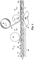
- FIG. 2 shows a sectional view of a portion of the sheeting 10, additionally showing a discontinuous film 24 of reflective material on the recessed faces 18, and a fill material 26 that fills cube corner cavities 22.
- Fill material 26 is preferably sufficiently transparent to allow light rays to propagate through it with minimal degradation of retroreflective efficiency.
- fill material 26 forms a strong bond not only with transparent cover layer 16 but also with film 24 and with any exposed portions of body layer 12.
- fill material 26 is preferably coextensive with the structured surface 14 and, for ease of construction, forms a substantially continuous layer that covers both the recessed faces and the top surfaces of the structured surface.
- the fill material can be coextensive with structured surface 14 but discontinuous, encapsulated by a network of bonds directly between cover layer 16 and top surfaces 20.
- a direct bond between the cover layer and the body layer can be made stronger than one in which the fill material and/or the reflective material are interposed.
- embodiments having a continuous fill material layer are preferred in part because the construction process is more robust by avoiding the stringent requirement of having to apply a precise amount of fill material to the structured surface-just enough to substantially fill the cavities, but not so much that the fill material covers the upper portions of the structured surface in a way that interferes with the network of bonds between the cover layer and upper portions of the body layer.
- the continuous fill material layer embodiments also allow the fill material to flow from one cube corner cavity to another before the fill material is solidified by cross-linking.
- a continuous fill material layer improves bond strength by increasing the surface area of the bond.
- Heat-activated adhesives can be used as the fill material with similar beneficial results.
- Examples of such adhesives are Nucrel brand ethylene acid copolymer resins, sold by E. I. du Pont de Nemours and Company.
- An advantage of heat-activated adhesives is that the release liner can in some cases be eliminated from the construction.
- the intermediate sheeting, without the cover layer and without a release liner, can be stored in a roll under standard storage conditions without adhering to itself.
- a disadvantage is that the sheeting must be heated to activate the adhesive properties when the cover layer is applied.
- a PSA or heat-activated adhesive can also be used as the fill material in applications where no cover layer is required.
- the sheeting thus retroreflects light incident from the opposite side of the window glass.
- a sheeting with a transparent PSA fill material and a release liner is particularly well suited.
- sheeting 10 preferably includes another thin adhesive layer 28 on the back side of body layer 12 so the sheeting can be applied to a substrate of interest.
- layer 28 is a PSA
- another release liner 28a is also included.
- Layer 28 need not be transparent and thus it can comprise a wider variety of PSAs than layer 26. However, if the same composition is used for layer 26 and 28, manufacturing inventory can be reduced.
- Radiation-curable materials that are not PSAs or PSA precursors can also be used to advantage. See, e.g., Examples 1-4 below. Such materials should have sufficient clarity to promote good retroreflectivity, have relatively low viscosity during application to the structured surface, and also have a sufficiently low shrinkage so that it maintains intimate contact with the structured surface after curing.
- Transparent PSA fill materials tend to be relatively expensive compared to fill materials disclosed in the prior art. Therefore, to keep production costs down it is advantageous when using the disclosed fill materials to use relatively inexpensive thermoplastic materials for body layer and cover layer compositions.
- other materials such as radiation-curable materials are also contemplated.
- FIG. 3 depicts a process for making cube corner cavity-based sheeting with the preferred fill materials.
- body layer 12 described above is provided the structured surface 14 by embossing, or by other processes used to make conventional rear-surface body layers.
- a film of reflective material 24 is then applied either discontinuously as shown in FIG. 2 , or continuously on both the recessed faces and the top surfaces 20. It is not necessary that the structured surface 14 have top surfaces 20, although such surfaces are useful for controlling daytime appearance and, in some instances, for improved bonding. In the absence of top surfaces 20, recessed faces 18 of adjacent cube corner elements intersect to form sharp edges.
- Film 24 can comprise metals such as aluminum, silver, nickel, tin, copper, or gold, or combinations thereof, or can comprise non-metals such as a multilayer dielectric stack. Such films can be applied by known physical or chemical deposition techniques, such as vacuum evaporation, sputtering, chemical vapor deposition ("CVD") or plasma-enhanced CVD, electroless deposition, and the like, depending upon the type of film desired.
- a given film can include multiple layers, including layers that promote adhesion to the body layer, barrier layers, and protective overcoat layers.
- a suitable film for polycarbonate-based body layers comprises about 1 nm thick titanium dioxide layer formed by sputtering titanium onto the body layer, followed by a 100 nm thick layer of evaporated aluminum. The titanium dioxide layer acts both as an adhesion promoter and a barrier layer to counteract pinholes typically present in the aluminum vapor coat.
- the body layer 12 so prepared is then sent through a fill material application station 30.
- a fill material application station 30 Generally, the more easily the fill material fills the cavities, the faster (and hence cheaper) the process can be run.
- Preferred fill materials have properties that permit rapid filling of the cube corner cavities. The fill material should adhere to the reflective film-covered recessed cube corner cavity faces without damaging the reflective film or other parts of the structured surface.
- a flowable fill material composition 32 is applied to the structured surface 14 ahead of a knife coater 34 whose position relative to a base plate 36 is adjusted to form a layer of composition 32 on the structured surface.
- vacuum assistance or inert gas purging can be used at the point of filling to further facilitate the operation.
- Some compositions 32 discussed in more detail below, have a relatively low viscosity at station 30 to permit rapid filling of the closed cube corner cavities. In contrast to prior art thermoplastic fill materials such compositions can exhibit these low viscosities at relatively low process temperatures, well below the glass transition temperature of typical body layer materials. For some fill materials, process temperatures at or around ambient room temperature are achievable.
- Composition 32 is suitable for forming a fill material that bonds well to all other parts of the sheeting that it contacts, including the reflective film 24, exposed portions of the body layer 12, and any cover layer (with the exception of a release liner that may be used as a temporary cover layer).
- fill material and body layer material can be used to produce a covalent bond therebetween for added robustness and durability.
- the covalent bond between the fill material and body layer can be formed during exposure to radiation.
- a fill material composition comprised of 25 wt. % tetrahydofurfuralacrylate (THF acrylate), 50 wt. % Ebecryl 8402 (available from Radcure), and 25 wt.
- a suitable body layer can comprise an ethylenepropylenedienemonomer (EPDM) based material, such as acrylic-EPDM-styrene (AES) polymers sold under the tradename Centrex (available from Bayer), Luran (available from BASF), or other polymers that crosslink upon exposure to radiation.
- EPDM ethylenepropylenedienemonomer
- AES acrylic-EPDM-styrene
- BASF BASF
- fill material reacts with these body layer materials at the top surfaces 20 upon exposure to crosslinking radiation to produce covalent bonds along the top surfaces.
- composition 32 is applied to the structured surface at fill material application station 30, the filled body layer is conveyed to a cover layer laminating station 38.
- radiation such as with a source of radiation 40
- some compositions 32 are composed of highly monomerized syrups which can chemically attack certain reflective films 24 or migrate through pinholes in the reflective film to attack the underlying body layer material. In such cases, it is preferable to polymerize and crosslink the compositions in situ shortly after application to the body layer so that damage to the sheeting can be minimized.
- the composition 32 remain flowable at least up to the laminating station 38.
- filled body layer 12 is conveyed between pressure rollers 42a,42b rotating oppositely as shown.
- a cover layer 44 unwound from a roll 46, passes through the nip between the rollers and is laminated to body layer 12.
- the fill material though preferably still not fully cross-linked, exhibits sufficient adhesion to hold cover layer 44 in place.
- the stippled appearance of composition 32 in FIGS. 3 and 4A-C indicates that it is not fully crosslinked and exhibits cold flow.
- composition 32 can be applied to the structured surface 14 by first being applied to the underside of the cover layer 44. Then, filling of the cube corner cavities and lamination of the cover layer can take place simultaneously at the lamination station 38.
- Cover layer 44 can comprise a transparent cover layer such as layer 16, to be used in the final sheeting product, or it can comprise a temporary layer such as a release liner. In either event another source of radiation 48 can be used to crosslink composition 32 to increase its shear and adhesive strength. Such crosslinked fill material is labeled 32a and depicted as cross-hatched rather than stippled. The fill material 32a does not exhibit significant cold-flow.
- cover layer 44 is a transparent cover layer such as layer 16.
- Source 48 is sufficiently intense, and layer 44 has a low enough absorption for at least some UV wavelengths, or for e-beam radiation, so that crosslinking can be effected through the cover layer as shown.
- the crosslinked composition 32a aggressively bonds to reflective film 24, body layer 12, and cover layer 44.
- the cover layer 44 has a higher UV absorption to better protect the remainder of the sheeting from degradation due to sunlight.
- Body layer 12 and reflective film 24 are then composed of materials having a lower absorption at the relevant UV wavelengths, and source 48 is disposed underneath instead of above the sheeting so as to expose the composition 32 to crosslinking radiation through body layer 12 and film 24.
- Silver used as reflective film 24 can be made sufficiently thin to allow adequate transmission in a UV spectral band located at about 360 nm.
- multilayer dielectric films can be easily tailored to have a high specular reflectance at the design wavelength and a transmission band in the UV.
- cover layer 44 is a release liner.
- the release liner is of conventional design, for example silicone-coated paper.
- the release liner may or may not be transparent at the design wavelength for the sheeting, and it may or may not have a low absorption of UV radiation. If absorption in the UV is low enough, source 48 can crosslink composition 32 through layer 44 as shown in FIG. 3 . Otherwise, the release liner can be removed just prior to crosslinking, or source 48 can be positioned to crosslink composition 32 from below the sheeting as discussed above.
- Sources 40, 48 can be adapted to emit UV light or other forms of radiation capable of carrying out the prescribed functions, for example, infrared radiation or electron beam radiation.
- a temporary sheeting comprising body layer 12, cover layer 44, and fill material 32 can be manufactured as shown in FIG. 3 except that source 48 is eliminated and the temporary sheeting is wound up in a roll and placed in storage.
- imperfections in the fill material layer tend to disappear due to flow of the uncured composition 32 from forces such as surface tension or other forces incident to the storage environment.
- the temporary sheeting can then be further processed by rapidly passing it near source 48 to expose composition 32 to radiation sufficient to produce crosslinked composition 32a, preferably a PSA. In some cases a relatively short delay may suffice, so that the temporary sheeting need not be wound up and stored.
- FIGS. 4A-C depict the sheeting 10 at different times after applying fill material to the structured surface 14 and after laminating cover layer 44 thereto, but before crosslinking the fill material.
- the production line speed of the body layer 12 has been increased to the point where complete filling of the cavities has not occurred, leaving a void 50 at the apex of each cavity.
- the cold flow properties of the composition 32 advantageously allow the fill material to advance into the cavities without the application of external forces and, typically, at standard process or storage temperatures, typically about 10 to about 40 degrees C. This behavior is referred to as self replication.
- voids 50 shrink ( FIG. 4B ), eventually disappearing altogether ( FIG. 4C ).
- Self replication via shrinkage of the voids is presumed to occur as gas in the voids diffuses into the fill material.
- the rate at which self replication occurs is dependent on the type of composition 32 used, the cover layer 44 properties (if a cover layer is used), the size of the cube corner cavities and the initial size of gaps 50, and on environmental factors such as temperature.
- Suitable fill materials include viscoelastic polymers which can attain the requisite transparency. Preferred materials exhibit cold flow at room temperature which allows the fill material to flow into the cavities of the body layer and also allows any entrapped gas to diffuse out, thus maintaining the optical performance of the sheeting. It is desirable further that the fill material exhibit little or no shrinkage upon curing such that it maintains intimate contact with the reflective recessed faces of the structured surface.
- a preferred class of materials includes acrylic polymers which may be pressure-sensitive adhesives at room temperature, or heat-activated adhesives which are substantially non-tacky at room temperature but become tacky at higher temperatures.
- the preferred acrylic polymers and copolymers are formed from acrylic or methacrylic acid esters of non-tertiary alkyl alcohols.
- the acrylic and methacrylic esters typically have a glass transition temperature below about 0°C.
- Examples of such monomers include n-butyl acrylate, isooctyl acrylate, 2-ethylhexyl acrylate, isononyl acrylate, isodecyl acrylate, decyl acrylate, lauryl acrylate, hexyl acrylate, and octadecyl acrylate, or combinations thereof and the like.
- Such monomeric acrylic or methacrylic esters are known and many are commercially available.
- the acrylic polymers typically include a copolymerizable monomer having a glass transition temperature above 0°C to enhance shear strength.
- Suitable copolymerizable monomers include acrylic acid, methacrylic acid, itaconic acid, n-vinyl pyrrolidone, n-vinyl caprolactam, substituted acrylamides such as N,N dimethylacrylamide, N-vinyl-2-pyrrolidone, N-vinyl caprolactam, acrylonitrile, isobornyl acrylate, tetrahydrofurfuryl acrylate, glycidyl acrylate, 2-phenoxyethylacrylate, benzylacrylate, acrylonitrile and methacrylonitrile or combinations thereof.
- the amounts of acrylate monomer to copolymerizable monomer can vary from 100 to about 30 parts of acrylate and correspondingly, 0 to 70 parts of copolymerizable monomer.
- the specific amounts of monomers are selected for the desired end use properties.
- the acrylic polymers may be prepared by emulsion polymerization, bulk polymerization, solvent polymerization, and the like, using appropriate polymerization initiators.
- Suitable pressure-sensitive adhesives for the invention are described in, for example, U.S. Patent Nos. 5,637,646 (Ellis ), 4,181,752 (Martens et al. ), and Re. 24,906 (Ulrich ), all incorporated herein by reference.
- Such materials include colorants, fluorescent dyes or pigments, chain transfer agents, plasticizers, tackifiers, antioxidants, stabilizers, cross-linking agents, and solvent.
- the fill material is preferably crosslinked to provide higher shear strength. In order to maintain optical performance, it is preferred that any entrapped gas or voids be allowed to escape or collapse before the fill material is crosslinked.
- Suitable cross-linking agents include those that are free radically copolymerizable with the acrylate monomers, and may be activated by radiation such as ultraviolet light. Additionally, crosslinking may be effected in the absence of cross-linking agents by means such as electron beam.
- crosslinking agents suitable for this application include free-radically copolymerizable crosslinking agents such as, for example, 4-acryloxybenzophenone, para-acryloxyethoxybenophenone, and para-N-(methacryloxyethyl)-carbamoylethoxybenophenone.
- Copolymerizable chemical cross linking agents are typically included in the amount of about 0% to about 2%, and preferred in the amount of about 0.025% to about 0.5%, based on the total weight of monomer(s).
- Other useful copolymerizable crosslinking agents are described in U.S. Pat. No. 4,737,559 (Kellen et al. ). The crosslinking is effected by ultraviolet light.
- a fill material composition may be polymerized in situ in the cavities of the sheeting by coating a monomeric or oligomeric composition onto the sheeting and polymerizing the compositions with heat or radiation.
- the composition has a viscosity that is sufficiently low prior to polymerization that any gas such as air diffuse out of the composition quickly prior, and the composition flows rapidly and easily to fill the cavities of the sheeting.
- Suitable crosslinking agents include those mentioned above as well as materials that crosslink during the polymerization process. Examples of this type of crosslinking agent include multifunctional acrylates such as 1,6 hexanedioldiacrylate and trimethylolpropanetriacrylate and substituted triazines described in U.S. Patent Nos.
- crosslinking agents may be used in amounts of from about 0.0001% to about 0.005% based on the weight of the monomers.
- the fill material may be applied to the sheeting by any suitable method.
- the polymers can be dispersed in a solvent or an emulsion, coated onto the sheeting, and drying off the solvent or water to leave the polymer in the cavities of the sheeting.
- the polymers may be hot melt coated onto the sheeting using known equipment such as extrusion coaters, rotary rod die coaters, and the like.
- the polymers may also be formed in the cavities of the sheeting as described above. Solvent-free processes are preferred because they eliminate environmental concerns associated with solvents and avoid formation of bubbles which may occur during drying of a solvent-containing composition.
- the body layer for retroreflective sheeting as described herein can be manufactured as a unitary material, e.g. by embossing a preformed sheet with an array of cube corner elements as described above or by casting a fluid material into a mold.
- the body layer can be manufactured as a layered product by casting a layer defining the structured surface against a preformed flat film analogous to the teachings of PCT Publication No. WO 95/11464 (Benson, Jr. et al. ) and U.S. Pat. No. 3,684,348 (Rowland ), or by laminating a preformed film to a preformed layer having cube corner cavities.
- Useful body layer materials are those that are dimensionally stable, durable, weatherable, and readily formable into the desired configuration.
- Examples include acrylics such as Plexiglas brand resin from Rohm and Haas, thermoset acrylates and epoxy acrylates, preferably radiation cured; polycarbonates; polyolefins; polyethylene-based ionomers (marketed under the name 'SURLYN'); polyesters; cellulose acetate butyrates; and polystyrenes.
- any material that is formable, typically under heat and pressure can be used.
- the sheeting can also include colorants, dyes, UV absorbers, or other additives as desired.
- Suitable transparent cover layer materials can also be of single or multilayer construction and can comprise materials that are optically transparent at least at a design wavelength and that are durable and weatherable.
- Thermoplastic or thermoset polymers, or combinations thereof, are generally acceptable.
- Acrylics, vinyl chloride, urethanes, ethylene acrylic acid (EAA) copolymers, polyesters, and fluoropolymers including polyvinylidene fluoride are preferred for weatherability.
- Corrosion inhibitors, UV stabilizers (absorbers), colorants including fluorescent dyes and pigments, abrasion resistant fillers, solvent resistant fillers, and the like can be included to provide desired optical or mechanical properties.
- the cover layer can have graphics, symbols, or other indicia so that the sheeting formed by the combination of the body layer and cover layer conveys useful information.
- thermoplastic polymers such as EAA, polyvinyl chloride, polystyrene, polyethylene-based ionomers, polymethylmethacrylate, polyester, and polycarbonate are as a whole relatively inexpensive and for that reason, to help offset the higher expense of typical radiation cured fill materials disclosed herein, they are desirable for use in the body layer and cover layer.
- the body layer also preferably has an elastic modulus greater than that of the fill material in order to maintain cube stability during deformation.
- the body layer elastic modulus is preferably greater than about 100,000 psi (690 MPa), measured in accordance with ASTM D882-97 "Standard Test Method for Tensile Properties of Thin Plastic Sheeting".
- the mold had a structured surface consisting of three sets of flat-bottomed grooves, and was the negative replica of a prior mold whose upper portions had been ground down flat with an abrasive.
- the embossed body layers were made of polycarbonate.
- the body layers for Examples 1 and 2 had a thickness of about 43 mils (1.1 mm) and included sufficient TiO 2 filler to make them opaque with a diffuse white surface appearance.
- Those for Examples 3 and 4 had a thickness of about 18 mils (0.46 mm) and included instead a red dye to give a diffuse red surface appearance.
- the structured surface of each body layer consisted essentially of three intersecting sets of parallel ridges.
- Two of the sets referred to as "secondary" ridge sets, had uniform ridge spacings of about 16 mils (408 ⁇ m) and intersected each other at an included angle of about 70 degrees.
- the other set of parallel ridges referred to as the "primary” ridge set, had a uniform spacing of about 14 mils (356 ⁇ m) and intersected each of the secondary ridge sets at an included angle of about 55 degrees. This produced cube corner cavity matched pairs canted at an angle of about 9.18 degrees. All of the ridges had substantially flat top surfaces whose transverse dimension was about 3.5 mils (89 ⁇ m) for the primary grooves and about 2.2 mils (56 ⁇ m) for the secondary grooves.
- the top surfaces were all non-smooth as a result of the abrasive action on the original mold discussed above, transferred to the body layers via the replication steps.
- the cube corner elements had a cube depth below the top surfaces of about 5.17 mils (131 ⁇ m).
- a silver film was vacuum deposited onto the structured surface of each sample to a thickness sufficient to render the film opaque yet highly reflective.
- the portion of the silver film disposed on the top surfaces was removed by lightly sanding with an abrasive.
- the silver film for Examples 1 and 3 was left undisturbed and continuous.
- a radiation-curable composition was prepared by combining (by weight) 74% Ebecryl 270 (a urethane acrylate available from Radcure), 25% Photomer 4127 (propoxylated neopently glycol diacrylate available from Henkel), and 1% Daracure 1173 (a photoinitiator available from Ciba-Geigy). This composition was then flow coated on the structured surface of all samples at room temperature to a thickness sufficient to fill the cube corner cavities and cover the top surfaces. The composition was flowable and had a viscosity of about 2000 centipoise (2 Pa-s) during filling. The samples were degassed at room temperature in a small vacuum chamber.
- the samples were removed from the chamber and covered with a 7 mil (178 ⁇ m) thick sheet of photo-grade PET sheeting to eliminate oxygen during subsequent curing.
- a heavy quartz plate having good transparency in the UV was placed on the PET sheeting and curing was then performed through the quartz plate and PET sheeting with UV light from a mercury lamp for about two minutes.
- the fill material composition had a sufficiently low shrinkage so that it hardened and bonded to the vapor-coated body layer.
- the composition did not bond to the PET sheeting, which was then removed.
- the cured composition was substantially clear and smooth but not permanently tacky. The sheetings so constructed all exhibited retroreflectivity.
- Examples 5-10) were natural, clear polystyrene and the remaining six (Examples 11-16) used polystyrene compounded with a titanium dioxide concentrate to impart diffuse whiteness.
- the body layers were each about 9 mils (230 ⁇ m) thick.
- the other set of parallel ridges referred to as the "primary" ridge set, had a uniform ridge spacing of about 5 mils (127 ⁇ m) and intersected each of the secondary ridge sets at an included angle of about 55 degrees.
- the ridges in each of the three ridge sets did not have top surfaces as defined herein but rather terminated at sharp upper portions whose transverse dimension was less than 0.0001 inches (2.5 ⁇ m).
- a continuous aluminum film about 100 nm thick was vacuum deposited onto the entire structured surface.
- a transparent hot melt PSA composition was prepared according to the procedure of Example 1 of U.S. Patent No. 5,753,768 (Ellis ) except as indicated below.
- a 200-gallon (757 liter) stainless steel batch reactor was charged with: 441.3 kilograms of isooctyl acrylate ("IOA”); 54.4 kg of acrylic acid ("AA”); 0.0017 parts of VazoTM 52 (2,2'-azobis(2,4-dimethylpentanenitrile)) per 100 parts of IOA and AA ("pph”); 0.0084 pph isooctylthioglycoate; 0.5 pph of a 25 weight % solids mixture of 4-acryloxy benzophenone in IOA; and 0.1 pph of IrganoxTM 1010 thermal stabilizer/antioxidant (tetrakis(methylene(3,5-di-tert-butyl-4-hydroxyhydrocinnamate))methane), manufactured by Ciba-Geigy Corporation
- the composition was then heated to 60 degrees C, held until polymerization began, and then reacted adiabatically. After the second adiabatic reaction cycle was completed, the resulting polymer composition had a 93% solids content.
- the batch of adhesive thus produced was then vacuum stripped to provide a pressure-sensitive adhesive polymer having an inherent viscosity of 0.44 dl/g and 0.1% or less residuals.
- the inherent viscosity was measured by conventional methods using a Cannon-Fenske #50 viscometer in a water bath controlled at 25°C, using the flow time of 10 ml of a polymer solution (0.2 g per deciliter polymer in ethyl acetate). The test procedure followed and the apparatus used are described in Textbook of Polymer Science, F.W. Billmeyer, Wiley-Interscience (Second Edition, 1971), pp. 84-85 .
- the prepared PSA composition was substantially completely polymerized and was permanently tacky at room temperature.
- the composition exhibited cold flow, yet strips of it could be cut from a bulk slab with a knife.
- the prepared PSA composition was then fed via a Haake 18 mm twin screw extruder into a 5 inch wide rotary rod die coater which applied the composition to the structured surface of the twelve body layers by hot melt coating.
- a rubber coated backup roll with a temperature varying between about 90 and 180 degrees F (32 and 82 degrees C) was used during this application step.
- the composition temperature as applied was determined by the extruder and die coater temperatures, ranging from about 325 to 375 degrees F (163 to 191 degrees C).
- Line speed of the body layer during fill material application was between about 10 and 20 ft/min (51 to 102 mm/sec).
- the applied composition coating was continuous and had a thickness of about 1-1.5 mils (25 to 38 ⁇ m) measured from the uppermost portions of the ridges on the structured surface.
- voids between the composition and the reflective film were observed at the cavity apices indicating poor replication-the composition had not fully filled the cube corner cavities (see FIG. 4A ).
- the voids appeared to occupy approximately 10-40% of the cube corner cavity volume.
- the observed retroreflectivity was poor.
- the PSA composition was left as coated and for the other samples the composition was crosslinked by exposure to a dosage of about 440 mJ/cm 2 of UV light as measured with an EIT UVIMAP, NIST units calibrated in the UVA spectral range.
- the crosslinked composition formed a PSA with high shear and cohesive strength with little or no cold flow.
- Three different transparent cover layers, each about 2 mils (50 ⁇ m) thick were then laminated to the PSA composition layer of the samples at ambient room temperature-an extruded impact-modified polymethylmethacrylate (PMMA) film was laminated to Examples 5, 8, 11, and 14, a plastisol-coated plasticized polyvinyl chloride (PVC) film was laminated to Examples 6, 9, 12, and 15, and an extruded polyethylene co-acrylic acid (EAA) film was laminated to Examples 7, 10, 13, and 16.
- PMMA polymethylmethacrylate
- PVC plastisol-coated plasticized polyvinyl chloride
- EAA extruded polyethylene co-acrylic acid
- the samples were wound up in rolls and maintained at ambient room temperature. Within several hours after lamination, the non-crosslinked samples (Examples 5-7 and 11-13) began to show significantly improved retroreflective performance indicative of the fill material flowing to more completely fill the cube corner cavities. After about 24 to 72 hours the fill material layer for those samples was substantially free of any voids. Apparently, the matter filling the voids diffused out of the sheeting during this time.
- the samples with the acrylic (PMMA) cover layer appeared to allow the most rapid rate of self replication; those with the EAA cover layer were somewhat slower; and those with the vinyl (PVC) cover layer yielded the slowest self replication rates of the samples tested.
- the crosslinked samples showed no visible improvement in replication fidelity of the fill material layer even after several months of storage at ambient room temperature.
- the non-crosslinked samples after complete replication of the fill material into the cube corner cavities of the structured surface, were thus ready for subsequent exposure to radiation sufficient to crosslink the fill material composition to increase its shear strength by solidification, while still maintaining its PSA characteristics.
- the coefficient of retroreflection was measured for all the non-crosslinked samples for -4 degree entrance angle and 0.2 degree observation angle, with values ranging from about 589 to about 982 cd/lx/m 2 .
- a roll of body layer retroreflective sheeting substantially the same as those of Examples 5-16 was prepared. The same structured surface geometry and reflective aluminum film was used.
- a pressure-sensitive adhesive resin composition was prepared by mixing 75 parts of isooctyl acrylate and 25 parts of N-vinylcaprolactam to yield about 2000 grams. Then 0.05 pph of a photoinitiator (2,4,6-trimethylbenzoyldiphenylphosphine available as LucirinTM TPO from BASF Corp.) was added. Nitrogen was bubbled through the composition and the composition was exposed to Sylvania black lights to partially polymerize it to a viscosity of about 1700 centipoise (1.7 Pa-s). The composition viscosity was measured using a model LVF Brookfield Viscometer equipped with a number 4 spindle at 60 rpm at room temperature.
- a photoinitiator 2,4,6-trimethylbenzoyldiphenylphosphine available as LucirinTM TPO from BASF Corp.
- the temperature of the composition increased from 23 °C to about 38°C.
- the composition was then sparged with air and cooled to room temperature.
- An additional 0.15 pph of photoinitiator (LucirinTM TPO) and 0.15 pph 1,6-hexanedioldiacrylate were added to it.
- the partially polymerized composition still substantially monomeric ( ⁇ 10% polymerized), was knife coated onto the body layer sheeting to a thickness of about 2 mils (50 ⁇ m) measured from the uppermost portions of the ridges on the structured surface, and then exposed to ultraviolet radiation in a nitrogen atmosphere to cure (polymerize and crosslink) the adhesive in situ.
- the ultraviolet radiation was provided by ultraviolet black lamps having most of the light emission between 300 and 400 nanometers, and a peak emission at about 350 nanometers.
- the light intensity averaged about 4.9 mW/cm 2 , and the total energy was about 498 mJ/cm 2 .
- the UV light was measured with an EIT UVMAP in NIST units. Due to the low viscosity and the wetting characteristics of the composition to the aluminum vapor coat, no voids were seen in the fill material within seconds of coating at the coating speed of 20 feet per minute. After curing, the adhesive was covered with a silicone-coated polypropylene release liner.
- Example 17 exhibited a good coefficient of retroreflectivity: the average value of measurements taken at 0 and 90 degree orientation angles, at a -4 degree entrance angle and 0.2 degree observation angle, was 1002 cd/lx/m 2 .
- Adhesive means a substance suitable for bonding two substrates together by surface attachment.
- the "body layer” of a retroreflective sheet or article that uses a structured surface for retroreflection is the layer (or layers) possessing the structured surface and chiefly responsible for maintaining the integrity of such structured surface.
- Cold flow refers to the ability of a material to flow under its own weight at ambient room temperature, about 20 degrees C.
- Cube corner cavity means a cavity bounded at least in part by three faces arranged as a cube corner element.
- “Cube corner element” means a set of three faces that cooperate to retroreflect light or to otherwise direct light to a desired location. "Cube corner element” also includes a set of three faces that itself does not retroreflect light or otherwise direct light to a desired location, but that if copied (in either a positive or negative sense) in a suitable substrate forms a set of three faces that does retroreflect light or otherwise direct light to a desired location.
- Cube corner pyramid means a mass of material having at least three side faces arranged as a cube corner element.
- Cube height or "cube depth” means, with respect to a cube corner element formed on or formable on a substrate, the maximum separation along an axis perpendicular to the substrate between portions of the cube corner element.
- Diffusely reflective means the property of reflecting a collimated incident light beam into a plurality of reflected light beams.
- Surfaces that are diffusely reflective also have a low specular reflectivity.
- Flowable refers to the ability of a material to flow under its own weight at a given temperature.
- “Geometric structure” means a protrusion or cavity having a plurality of faces.
- “Groove” means a cavity elongated along a groove axis and bounded at least in part by two opposed groove side surfaces.
- “Groove side surface” means a surface or series of surfaces capable of being formed by drawing one or more cutting tools across a substrate in a substantially continuous linear motion. Such motion includes fly-cutting techniques where the cutting tool has a rotary motion as it advances along a substantially linear path.
- Heat-activated adhesive means a solid thermoplastic material that melts upon heating and then sets to a firm bond upon cooling.
- X% polymerized means 100% minus the weight % of unreacted monomer in a composition.
- PSA Pressure-sensitive adhesive
- Randomness curable means the capacity of a composition to undergo polymerization and/or crosslinking upon exposure to ultraviolet radiation, visible radiation, electron beam radiation, or the like, or combinations thereof, optionally with an appropriate catalyst or initiator.
- “Retroreflective” means having the characteristic that obliquely incident incoming light is reflected in a direction antiparallel to the incident direction, or nearly so, such that an observer at or near the source of light can detect the reflected light.
- Structured when used in connection with a surface means a surface composed of a plurality of distinct faces arranged at various orientations.
- Symmetry axis when used in connection with a cube corner element refers to the axis that extends through the cube corner apex and forms an equal angle with the three faces of the cube corner element. It is also sometimes referred to as the optical axis of the cube corner element.
- Transparent with regard to a layer or substance for use in a retroreflective sheeting, means able to transmit light of a desired wavelength to a degree that does not prevent retroreflection.
- Top surfaces of a structured surface that also contains recessed faces refers to surfaces that are distinct from the recessed faces and that have a minimum width in plan view of at least about 0.0001 inches (2.5 ⁇ m).
- Viscosity means the internal resistance to flow exhibited by a fluid at a given temperature. Low to moderate viscosities are typically measured using a rotating spindle in contact with the fluid and expressed in SI units of Pascal-seconds (Pa-s). The viscosity of highly viscous polymers can be measured by dissolving the polymer in a solvent and comparing the efflux times, as described in Textbook of Polymer Science, F. W. Billmeyer, Wiley-Interscience (Second Edition, 1971), pp. 84-85 . A viscosity measured by the latter approach is referred to as "inherent viscosity" and expressed in units of inverse concentration, such as deciliters per gram (dl/g).
Landscapes
- Physics & Mathematics (AREA)
- Engineering & Computer Science (AREA)
- General Physics & Mathematics (AREA)
- Optics & Photonics (AREA)
- Health & Medical Sciences (AREA)
- Manufacturing & Machinery (AREA)
- Ophthalmology & Optometry (AREA)
- Mechanical Engineering (AREA)
- Optical Elements Other Than Lenses (AREA)
- Laminated Bodies (AREA)
Claims (7)
- Retroreflektierender Artikel, umfassend:eine Körperschicht (12) mit einer strukturierten Oberfläche (14), umfassend vertiefte Flächen (18), die Würfeleckenhohlräume (22) definieren;eine reflektierende Folie (24), die zumindest auf den vertieften Flächen angeordnet ist; undeine Schicht aus fließfähiger strahlungshärtbarer Zusammensetzung (26), die die Würfeleckenhohlräume ausfüllt.
- Artikel nach Anspruch 1, wobei die Zusammensetzungsschicht im Wesentlichen flächengleich mit der strukturierten Oberfläche ist.
- Artikel nach Anspruch 2, wobei die Zusammensetzungsschicht im Wesentlichen die gesamte strukturierte Oberfläche bedeckt.
- Artikel nach Anspruch 1, wobei die Zusammensetzung im Wesentlichen polymer ist.
- Artikel nach Anspruch 1, wobei die Zusammensetzung zum Bilden eines transparenten druckempfindlichen Klebstoffs geeignet ist.
- Artikel nach Anspruch 1, wobei die Zusammensetzung eine ausreichend geringe Schrumpfung aufweist; sodass sie nach dem Härten einen engen Kontakt mit den vertieften Flächen aufrechterhält.
- Artikel nach Anspruch 1, wobei die reflektierende Folie diskontinuierlich ist und die Zusammensetzung geeignet ist, um mit freiliegenden Abschnitten der Körperschicht eine kovalente Bindung zu bilden.
Applications Claiming Priority (2)
| Application Number | Priority Date | Filing Date | Title |
|---|---|---|---|
| US09/228,367 US6280822B1 (en) | 1999-01-11 | 1999-01-11 | Cube corner cavity based retroeflectors with transparent fill material |
| EP99921897A EP1145050B1 (de) | 1999-01-11 | 1999-05-12 | Retroreflektoren mit würfeleckigen hohlräumen gefüllt mit lichtdurchlässigem material |
Related Parent Applications (2)
| Application Number | Title | Priority Date | Filing Date |
|---|---|---|---|
| EP99921897A Division EP1145050B1 (de) | 1999-01-11 | 1999-05-12 | Retroreflektoren mit würfeleckigen hohlräumen gefüllt mit lichtdurchlässigem material |
| EP99921897.7 Division | 1999-05-12 |
Publications (3)
| Publication Number | Publication Date |
|---|---|
| EP2267494A2 EP2267494A2 (de) | 2010-12-29 |
| EP2267494A3 EP2267494A3 (de) | 2011-04-20 |
| EP2267494B1 true EP2267494B1 (de) | 2016-06-22 |
Family
ID=22856896
Family Applications (4)
| Application Number | Title | Priority Date | Filing Date |
|---|---|---|---|
| EP99921897A Expired - Lifetime EP1145050B1 (de) | 1999-01-11 | 1999-05-12 | Retroreflektoren mit würfeleckigen hohlräumen gefüllt mit lichtdurchlässigem material |
| EP10179858.5A Expired - Lifetime EP2267494B1 (de) | 1999-01-11 | 1999-05-12 | Retroreflektoren mit würfeleckigen hohlräumen gefüllt mit lichtdurchlässigem material |
| EP10179862.7A Expired - Lifetime EP2261700B1 (de) | 1999-01-11 | 1999-05-12 | Retroreflektoren mit würfeleckigen hohlräumen gefüllt mit lichtdurchlässigem material |
| EP10179861.9A Expired - Lifetime EP2267495B1 (de) | 1999-01-11 | 1999-05-12 | Retroreflektoren mit würfeleckigen hohlräumen gefüllt mit lichtdurchlässigem material |
Family Applications Before (1)
| Application Number | Title | Priority Date | Filing Date |
|---|---|---|---|
| EP99921897A Expired - Lifetime EP1145050B1 (de) | 1999-01-11 | 1999-05-12 | Retroreflektoren mit würfeleckigen hohlräumen gefüllt mit lichtdurchlässigem material |
Family Applications After (2)
| Application Number | Title | Priority Date | Filing Date |
|---|---|---|---|
| EP10179862.7A Expired - Lifetime EP2261700B1 (de) | 1999-01-11 | 1999-05-12 | Retroreflektoren mit würfeleckigen hohlräumen gefüllt mit lichtdurchlässigem material |
| EP10179861.9A Expired - Lifetime EP2267495B1 (de) | 1999-01-11 | 1999-05-12 | Retroreflektoren mit würfeleckigen hohlräumen gefüllt mit lichtdurchlässigem material |
Country Status (8)
| Country | Link |
|---|---|
| US (6) | US6280822B1 (de) |
| EP (4) | EP1145050B1 (de) |
| JP (2) | JP2002535691A (de) |
| KR (1) | KR100638688B1 (de) |
| CN (1) | CN1334927B (de) |
| AU (1) | AU761278B2 (de) |
| CA (1) | CA2357420A1 (de) |
| WO (1) | WO2000042453A1 (de) |
Families Citing this family (64)
| Publication number | Priority date | Publication date | Assignee | Title |
|---|---|---|---|---|
| US6280822B1 (en) * | 1999-01-11 | 2001-08-28 | 3M Innovative Properties Company | Cube corner cavity based retroeflectors with transparent fill material |
| WO2000043813A1 (en) * | 1999-01-21 | 2000-07-27 | Reflexite Corporation | Durable, open-faced retroreflective prismatic construction |
| US6967053B1 (en) * | 1999-01-21 | 2005-11-22 | Reflexite Corporation | Durable, open-faced retroreflective prismatic construction |
| US20050185279A1 (en) * | 1999-01-21 | 2005-08-25 | Reflexite Corporation | Durable, open-faced retroreflective prismatic construction |
| JP3971529B2 (ja) * | 1999-03-03 | 2007-09-05 | 日本カーバイド工業株式会社 | 再帰反射シート |
| US6884371B2 (en) * | 2003-03-06 | 2005-04-26 | 3M Innovative Properties Company | Method of making retroreflective sheeting and articles |
| CA2603382A1 (en) * | 2005-03-12 | 2006-09-21 | 3M Innovative Properties Company | Illumination devices and methods for making the same |
| JP4890800B2 (ja) * | 2005-06-29 | 2012-03-07 | スリーエム イノベイティブ プロパティズ カンパニー | 透明波長選択性再帰反射体 |
| US7294861B2 (en) * | 2005-06-30 | 2007-11-13 | 3M Innovative Properties Company | Phosphor tape article |
| US20070001182A1 (en) * | 2005-06-30 | 2007-01-04 | 3M Innovative Properties Company | Structured phosphor tape article |
| US7815355B2 (en) * | 2005-08-27 | 2010-10-19 | 3M Innovative Properties Company | Direct-lit backlight having light recycling cavity with concave transflector |
| TWI464494B (zh) * | 2005-08-27 | 2014-12-11 | 3M新設資產公司 | 照明組件及系統 |
| US20070047228A1 (en) * | 2005-08-27 | 2007-03-01 | 3M Innovative Properties Company | Methods of forming direct-lit backlights having light recycling cavity with concave transflector |
| US7537374B2 (en) * | 2005-08-27 | 2009-05-26 | 3M Innovative Properties Company | Edge-lit backlight having light recycling cavity with concave transflector |
| US7611251B2 (en) | 2006-04-18 | 2009-11-03 | 3M Innovative Properties Company | Retroreflective articles comprising olefinic seal films |
| US8525402B2 (en) | 2006-09-11 | 2013-09-03 | 3M Innovative Properties Company | Illumination devices and methods for making the same |
| US8581393B2 (en) * | 2006-09-21 | 2013-11-12 | 3M Innovative Properties Company | Thermally conductive LED assembly |
| US7481563B2 (en) * | 2006-09-21 | 2009-01-27 | 3M Innovative Properties Company | LED backlight |
| EP2106339B1 (de) * | 2007-01-19 | 2012-08-29 | Koninklijke Philips Electronics N.V. | Optisches element mit mindestens einem eingebetteten reflektor und verfahren der herstellung |
| US8224189B1 (en) * | 2007-02-02 | 2012-07-17 | Sunlight Photonics Inc. | Retro-directive target for free-space optical communication and method of producing the same |
| US7976741B2 (en) * | 2007-02-12 | 2011-07-12 | Ichia Technologies, Inc. | Method of manufacturing light guide plate of keypad |
| WO2008109420A2 (en) | 2007-03-02 | 2008-09-12 | Technology Solutions & Invention Llc | Two-sided corner-cube retroreflectors and methods of manufacturing the same |
| US20080295327A1 (en) * | 2007-06-01 | 2008-12-04 | 3M Innovative Properties Company | Flexible circuit |
| WO2009002225A2 (ru) * | 2007-06-25 | 2008-12-31 | Closed Company 'molecular-Medicine Technologies' | Многофункциональное устройство для диагностики и способ тестирования биологических объектов |
| CN101344674B (zh) * | 2007-07-12 | 2010-11-17 | 颖台科技股份有限公司 | 光学膜片及其制造方法以及应用该光学膜片的背光模块 |
| RU2497161C2 (ru) * | 2008-01-14 | 2013-10-27 | Эйвери Деннисон Корпорейшн | Ретроотражатель для применения в прикладных задачах, связанных с сенсорными экранами, и в системах позиционирования |
| KR100925994B1 (ko) * | 2008-05-02 | 2009-11-09 | 김강현 | 재귀반사시트 및 그 제조방법 |
| CN102131958B (zh) * | 2008-06-30 | 2013-12-25 | 3M创新有限公司 | 形成微结构的方法 |
| CN102138086B (zh) | 2008-07-10 | 2014-11-26 | 3M创新有限公司 | 具有粘弹性光导的回射制品和装置 |
| EP2310885B1 (de) * | 2008-07-10 | 2017-03-29 | 3M Innovative Properties Company | Rückstrahlende artikel und vorrichtungen mit viskoelastischem lichtleiter |
| JP5457447B2 (ja) | 2008-07-10 | 2014-04-02 | スリーエム イノベイティブ プロパティズ カンパニー | 粘弾性導光材 |
| CN107037526A (zh) | 2008-08-08 | 2017-08-11 | 3M创新有限公司 | 具有粘弹性层的用于控制光的光导 |
| EP2161597B1 (de) * | 2008-09-03 | 2014-06-04 | Brainlab AG | Bildgestütztes Operationssystem |
| US20100113692A1 (en) * | 2008-11-04 | 2010-05-06 | Mcguire Jr James E | Apparatus for Continuous Production of Partially Polymerized Compositions |
| US8765217B2 (en) | 2008-11-04 | 2014-07-01 | Entrotech, Inc. | Method for continuous production of (meth)acrylate syrup and adhesives therefrom |
| ES2360777B1 (es) * | 2009-01-30 | 2012-05-03 | Nematia Ingenieria Integral, S.L. | Reflector solar y procedimiento de fabricación. |
| US8329079B2 (en) | 2009-04-20 | 2012-12-11 | Entrochem, Inc. | Method and apparatus for continuous production of partially polymerized compositions and polymers therefrom |
| JP5662049B2 (ja) * | 2009-05-15 | 2015-01-28 | デクセリアルズ株式会社 | 光学体およびその製造方法、窓材、建具、ならびに日射遮蔽装置 |
| BR112012001292A2 (pt) | 2009-07-21 | 2019-09-24 | 3M Innovantive Properties Company | conjunto de luz |
| KR101926406B1 (ko) * | 2009-12-11 | 2018-12-07 | 넥스트 홀딩스 리미티드 | 터치 스크린용 위치 검출 시스템 및 이에 사용하는 프리즘 필름 |
| JP6057717B2 (ja) | 2009-12-21 | 2017-01-11 | スリーエム イノベイティブ プロパティズ カンパニー | 半透過性物品及びライトアセンブリ |
| JP5608385B2 (ja) * | 2010-02-08 | 2014-10-15 | デクセリアルズ株式会社 | 光学体およびその製造方法、窓材、建具、ならびに日射遮蔽装置 |
| KR20120115568A (ko) | 2010-02-10 | 2012-10-18 | 쓰리엠 이노베이티브 프로퍼티즈 컴파니 | 점탄성 층을 구비한 조명 장치 |
| JP2011180449A (ja) * | 2010-03-02 | 2011-09-15 | Sony Corp | 光学体およびその製造方法、窓材、ならびに光学体の貼り合わせ方法 |
| JP5586300B2 (ja) * | 2010-03-31 | 2014-09-10 | デクセリアルズ株式会社 | 機能性積層体及び機能性構造体 |
| US20110291330A1 (en) * | 2010-05-27 | 2011-12-01 | Mircea Despa | Replication method and articles of the method |
| JP2012003026A (ja) * | 2010-06-16 | 2012-01-05 | Sony Corp | 光学体、窓材、建具および日射遮蔽装置 |
| JP2012108213A (ja) * | 2010-11-16 | 2012-06-07 | Koito Mfg Co Ltd | 再帰反射鏡及びその製造方法 |
| CN102967892B (zh) * | 2011-08-30 | 2015-12-02 | 原相科技股份有限公司 | 用于光学式触控装置的反光镜及使用该反光镜的光学式触控装置 |
| GB201117058D0 (en) * | 2011-10-04 | 2011-11-16 | Qinetiq Ltd | Infrared transparent film |
| WO2013165977A1 (en) * | 2012-05-03 | 2013-11-07 | 3M Innovative Properties Company | Durable solar mirror films |
| WO2013165891A1 (en) * | 2012-05-03 | 2013-11-07 | 3M Innovative Properties Company | Durable solar mirror films |
| US10800112B2 (en) | 2016-09-12 | 2020-10-13 | Textron Innovations, Inc. | Bonding process and system |
| CN108181712A (zh) * | 2016-12-08 | 2018-06-19 | 未来(北京)黑科技有限公司 | 用于在空中成像的系统 |
| CN108181714A (zh) * | 2016-12-08 | 2018-06-19 | 未来(北京)黑科技有限公司 | 用于在空中成像的系统 |
| CN108181713A (zh) * | 2016-12-08 | 2018-06-19 | 未来(北京)黑科技有限公司 | 用于在空中成像的系统 |
| JP2018101014A (ja) * | 2016-12-19 | 2018-06-28 | デクセリアルズ株式会社 | 光学体 |
| JP2018101012A (ja) * | 2016-12-19 | 2018-06-28 | デクセリアルズ株式会社 | 光学体 |
| JP2018101016A (ja) * | 2016-12-19 | 2018-06-28 | デクセリアルズ株式会社 | 機能性フィルム |
| DE102017105935B4 (de) * | 2017-03-20 | 2021-09-02 | Preh Gmbh | Verfahren zum vollflächigen Verbinden von antiparallel verlaufenden Kontaktflächen eines ersten und zweiten Fügepartners mittels eines Formlings |
| JP7122088B2 (ja) * | 2017-06-22 | 2022-08-19 | 景義 片倉 | 広角再帰音波反射体 |
| EP3793828B1 (de) * | 2019-08-08 | 2022-07-20 | Preh GmbH | Kunststoffverbundblende sowie zugehöriges herstellungsverfahren |
| CA3200663A1 (en) * | 2020-11-05 | 2022-05-12 | Berry Global, Inc. | Multilayer film |
| WO2025133762A1 (en) | 2023-12-21 | 2025-06-26 | 3M Innovative Properties Company | Retroreflective article comprising a retroreflective layer and an antireflective layer, kits, and methods thereof |
Citations (1)
| Publication number | Priority date | Publication date | Assignee | Title |
|---|---|---|---|---|
| WO1997001118A1 (en) * | 1995-06-22 | 1997-01-09 | Minnesota Mining And Manufacturing Company | Encapsulated-lens retroreflective sheeting |
Family Cites Families (57)
| Publication number | Priority date | Publication date | Assignee | Title |
|---|---|---|---|---|
| US2380447A (en) * | 1945-07-31 | Optical reflecting material | ||
| USRE24906E (en) | 1955-11-18 | 1960-12-13 | Pressure-sensitive adhesive sheet material | |
| US3396639A (en) | 1965-09-23 | 1968-08-13 | Jerome H. Lemelson | Reflecting devices |
| DE1646235A1 (de) | 1967-02-18 | 1971-07-29 | Guenter Gubela | Reflektor aus Kunststoff fuer Verkehrszeichen od.dgl. |
| US3716445A (en) | 1970-06-24 | 1973-02-13 | J Lemelson | Reflex reflective sheeting |
| US3810804A (en) | 1970-09-29 | 1974-05-14 | Rowland Dev Corp | Method of making retroreflective material |
| US3684348A (en) * | 1970-09-29 | 1972-08-15 | Rowland Dev Corp | Retroreflective material |
| US3689346A (en) | 1970-09-29 | 1972-09-05 | Rowland Dev Corp | Method for producing retroreflective material |
| US3712706A (en) | 1971-01-04 | 1973-01-23 | American Cyanamid Co | Retroreflective surface |
| US3811983A (en) | 1972-06-23 | 1974-05-21 | Rowland Dev Corp | Method for producing retroreflective sheeting |
| US3935359A (en) | 1972-06-23 | 1976-01-27 | Rowland Development Corporation | Retroreflective sheeting and method and apparatus for producing same |
| US3822158A (en) | 1972-08-14 | 1974-07-02 | K Hoffman | Method of refurbishing reflective-type pavement markers |
| US4181752A (en) | 1974-09-03 | 1980-01-01 | Minnesota Mining And Manufacturing Company | Acrylic-type pressure sensitive adhesives by means of ultraviolet radiation curing |
| US4127693A (en) | 1975-02-10 | 1978-11-28 | Lemelson Jerome H | Reflex reflectors with pyramid-shaped indentations |
| US4025159A (en) * | 1976-02-17 | 1977-05-24 | Minnesota Mining And Manufacturing Company | Cellular retroreflective sheeting |
| US4165266A (en) * | 1977-03-30 | 1979-08-21 | Union Carbide Corporation | Radiation curable pressure sensitive adhesive compositions |
| US4576850A (en) | 1978-07-20 | 1986-03-18 | Minnesota Mining And Manufacturing Company | Shaped plastic articles having replicated microstructure surfaces |
| US4329384A (en) | 1980-02-14 | 1982-05-11 | Minnesota Mining And Manufacturing Company | Pressure-sensitive adhesive tape produced from photoactive mixture of acrylic monomers and polynuclear-chromophore-substituted halomethyl-2-triazine |
| US4330590A (en) | 1980-02-14 | 1982-05-18 | Minnesota Mining And Manufacturing Company | Photoactive mixture of acrylic monomers and chromophore-substituted halomethyl-2-triazine |
| CH657212A5 (de) | 1982-01-13 | 1986-08-15 | Wild Heerbrugg Ag | Verfahren zur herstellung von metallreflektoren und vorrichtung zur durchfuehrung des verfahrens. |
| US4656072A (en) | 1985-06-17 | 1987-04-07 | Coburn Corporation | Retroreflective material for providing a colored decorative effect in visible light |
| US4737559A (en) | 1986-05-19 | 1988-04-12 | Minnesota Mining And Manufacturing Co. | Pressure-sensitive adhesive crosslinked by copolymerizable aromatic ketone monomers |
| US4703999A (en) | 1986-06-16 | 1987-11-03 | Minnesota Mining And Manufacturing Company | Wide-angle-reflective cube-corner retroreflective sheeting |
| GB8800710D0 (en) | 1988-01-13 | 1988-02-10 | Scient Applied Research Sar | Reflective material |
| US4981743A (en) * | 1988-07-25 | 1991-01-01 | Unisys Corporation | Overcoat composition for optical record |
| US5175030A (en) | 1989-02-10 | 1992-12-29 | Minnesota Mining And Manufacturing Company | Microstructure-bearing composite plastic articles and method of making |
| US5122902A (en) | 1989-03-31 | 1992-06-16 | Minnesota Mining And Manufacturing Company | Retroreflective articles having light-transmissive surfaces |
| JP2922283B2 (ja) * | 1990-09-28 | 1999-07-19 | 日本カーバイド工業株式会社 | 熱硬化性感圧接着剤組成物用アクリル系共重合体 |
| US5254390B1 (en) | 1990-11-15 | 1999-05-18 | Minnesota Mining & Mfg | Plano-convex base sheet for retroreflective articles |
| US5557460A (en) * | 1990-11-26 | 1996-09-17 | Reginald Bennett International Inc. | Two sided marker |
| CA2064484C (en) | 1991-04-11 | 1998-08-11 | William P. Rowland | Retroreflective sheet |
| US5234740A (en) * | 1991-08-28 | 1993-08-10 | Minnesota Mining And Manufacturing Company | Slip control sheeting and articles covered with same |
| US5189553A (en) | 1992-06-08 | 1993-02-23 | Minnesota Mining And Manufacturing Company | Optimized construction of retroreflective articles for curved applications |
| JPH06214103A (ja) | 1993-01-14 | 1994-08-05 | Nippon Carbide Ind Co Inc | キューブコーナー型反射要素の製造方法 |
| US5376431A (en) | 1993-05-12 | 1994-12-27 | Reflexite Corporation | Retroreflective microprism sheeting with silver/copper reflecting coating and method of making same |
| KR100437958B1 (ko) | 1993-10-20 | 2004-08-25 | 미네소타 마이닝 앤드 매뉴팩춰링 캄파니 | 초가요성,역반사성입방체모서리를지닌복합시트및이의제조방법 |
| US5614286A (en) * | 1993-10-20 | 1997-03-25 | Minnesota Mining And Manufacturing Company | Conformable cube corner retroreflective sheeting |
| US5691846A (en) | 1993-10-20 | 1997-11-25 | Minnesota Mining And Manufacturing Company | Ultra-flexible retroreflective cube corner composite sheetings and methods of manufacture |
| US5602221A (en) | 1993-11-10 | 1997-02-11 | Minnesota Mining And Manufacturing Company | Pressure sensitive adhesives with good low energy surface adhesion |
| US5780140A (en) | 1996-09-23 | 1998-07-14 | Reflexite Corporation | Retroreflective microprismatic material with top face curvature and method of making same |
| JP3350266B2 (ja) * | 1994-12-09 | 2002-11-25 | ダイハツ工業株式会社 | 熱硬化性両面接着テープ及びそれを用いた自動車の付属物取付け構造体 |
| KR100439926B1 (ko) | 1995-04-21 | 2004-07-12 | 텍스트론 오토모티브 인테리얼즈 인크. | 방사선 경화형 아일랜드 코팅 시스템 |
| US5840407A (en) | 1995-04-25 | 1998-11-24 | Minnesota Mining And Manufacturing Co. | Optical film to simulate beveled glass |
| US5657162A (en) | 1995-07-26 | 1997-08-12 | Reflexite Corporation | Retroreflective articles with multiple size prisms in multiple locations |
| US5637646A (en) | 1995-12-14 | 1997-06-10 | Minnesota Mining And Manufacturing Company | Bulk radical polymerization using a batch reactor |
| US5735988A (en) * | 1996-03-19 | 1998-04-07 | Physical Optics Corporation | Method of making liquid crystal display system |
| US5754338A (en) | 1996-04-01 | 1998-05-19 | Minnesota Mining And Manufacturing Company | Structured retroreflective sheeting having a rivet-like connection |
| US5763049A (en) * | 1996-04-30 | 1998-06-09 | Minnesota Mining And Manufacturing Company | Formed ultra-flexible retroreflective cube-corner composite sheeting with target optical properties and method for making same |
| JPH1092144A (ja) | 1996-09-18 | 1998-04-10 | Tdk Corp | テープカセット |
| US5734501A (en) | 1996-11-01 | 1998-03-31 | Minnesota Mining And Manufacturing Company | Highly canted retroreflective cube corner article |
| JPH10242084A (ja) | 1997-02-24 | 1998-09-11 | Lintec Corp | ウェハ貼着用粘着シートおよび電子部品の製造方法 |
| US6160084A (en) * | 1998-02-23 | 2000-12-12 | Massachusetts Institute Of Technology | Biodegradable shape memory polymers |
| US6287670B1 (en) * | 1999-01-11 | 2001-09-11 | 3M Innovative Properties Company | Cube corner cavity based retroreflectors and methods for making same |
| US6280822B1 (en) * | 1999-01-11 | 2001-08-28 | 3M Innovative Properties Company | Cube corner cavity based retroeflectors with transparent fill material |
| US6540367B1 (en) | 1999-04-07 | 2003-04-01 | 3M Innovative Properties Company | Structured surface articles containing geometric structures with compound faces and methods for making same |
| DE20320318U1 (de) | 2003-06-27 | 2004-11-11 | Gühring, Jörg, Dr. | Werkzeug zum Entgraten |
| JP2006009753A (ja) | 2004-06-29 | 2006-01-12 | Nissan Motor Co Ltd | 車両用エンジン排気装置 |
-
1999
- 1999-01-11 US US09/228,367 patent/US6280822B1/en not_active Expired - Lifetime
- 1999-05-12 EP EP99921897A patent/EP1145050B1/de not_active Expired - Lifetime
- 1999-05-12 AU AU38994/99A patent/AU761278B2/en not_active Ceased
- 1999-05-12 WO PCT/US1999/010347 patent/WO2000042453A1/en not_active Ceased
- 1999-05-12 CA CA002357420A patent/CA2357420A1/en not_active Abandoned
- 1999-05-12 EP EP10179858.5A patent/EP2267494B1/de not_active Expired - Lifetime
- 1999-05-12 EP EP10179862.7A patent/EP2261700B1/de not_active Expired - Lifetime
- 1999-05-12 JP JP2000593971A patent/JP2002535691A/ja not_active Withdrawn
- 1999-05-12 EP EP10179861.9A patent/EP2267495B1/de not_active Expired - Lifetime
- 1999-05-12 CN CN998161071A patent/CN1334927B/zh not_active Expired - Fee Related
- 1999-05-12 KR KR1020017008705A patent/KR100638688B1/ko not_active Expired - Fee Related
-
2001
- 2001-05-30 US US09/870,180 patent/US7182829B2/en not_active Expired - Fee Related
- 2001-05-30 US US09/870,226 patent/US7452588B2/en not_active Expired - Fee Related
-
2005
- 2005-10-18 US US11/252,670 patent/US20060108062A1/en not_active Abandoned
-
2009
- 2009-03-10 US US12/401,294 patent/US8596799B2/en not_active Expired - Fee Related
-
2010
- 2010-03-17 JP JP2010060688A patent/JP4991894B2/ja not_active Expired - Fee Related
-
2011
- 2011-10-14 US US13/273,419 patent/US8596801B2/en not_active Expired - Fee Related
Patent Citations (1)
| Publication number | Priority date | Publication date | Assignee | Title |
|---|---|---|---|---|
| WO1997001118A1 (en) * | 1995-06-22 | 1997-01-09 | Minnesota Mining And Manufacturing Company | Encapsulated-lens retroreflective sheeting |
Also Published As
| Publication number | Publication date |
|---|---|
| JP2002535691A (ja) | 2002-10-22 |
| EP2267494A2 (de) | 2010-12-29 |
| EP1145050A1 (de) | 2001-10-17 |
| EP2267495B1 (de) | 2016-06-22 |
| KR20010101448A (ko) | 2001-11-14 |
| JP4991894B2 (ja) | 2012-08-01 |
| JP2010164990A (ja) | 2010-07-29 |
| US20090169823A1 (en) | 2009-07-02 |
| US20120120491A1 (en) | 2012-05-17 |
| EP2267495A2 (de) | 2010-12-29 |
| US6280822B1 (en) | 2001-08-28 |
| EP2267494A3 (de) | 2011-04-20 |
| CN1334927A (zh) | 2002-02-06 |
| EP2261700A1 (de) | 2010-12-15 |
| WO2000042453A1 (en) | 2000-07-20 |
| AU3899499A (en) | 2000-08-01 |
| US8596801B2 (en) | 2013-12-03 |
| US8596799B2 (en) | 2013-12-03 |
| EP2267495A3 (de) | 2011-04-20 |
| US20060108062A1 (en) | 2006-05-25 |
| EP2261700B1 (de) | 2016-06-22 |
| US20010033906A1 (en) | 2001-10-25 |
| EP1145050B1 (de) | 2011-10-19 |
| CN1334927B (zh) | 2011-05-18 |
| AU761278B2 (en) | 2003-05-29 |
| KR100638688B1 (ko) | 2006-10-27 |
| US20010033907A1 (en) | 2001-10-25 |
| US7182829B2 (en) | 2007-02-27 |
| CA2357420A1 (en) | 2000-07-20 |
| US7452588B2 (en) | 2008-11-18 |
Similar Documents
| Publication | Publication Date | Title |
|---|---|---|
| EP2267494B1 (de) | Retroreflektoren mit würfeleckigen hohlräumen gefüllt mit lichtdurchlässigem material | |
| EP2010945B1 (de) | Retroreflektierende gegenstände umfassend olefinische siegelfolien | |
| EP2577366B1 (de) | Mehrschichtige dichtungsfilme | |
| KR100380677B1 (ko) | 재귀성반사시트및재귀성반사성능을갖는물품 | |
| AU727295B2 (en) | Retroreflective sheeting with coated back surface | |
| MXPA97008444A (en) | Retrorreflectora sheet and article that has retrorreflectivi | |
| JP2007010893A (ja) | 透明波長選択性再帰反射体 | |
| EP1627246B1 (de) | Retroreflektiver artikel mit mikrostrukturierter haftschicht | |
| EP3317702B1 (de) | Barriereelement auf einem mikrostrukturierten artikel | |
| MXPA01006940A (en) | Cube corner cavity based retroreflectors with transparent fill material |
Legal Events
| Date | Code | Title | Description |
|---|---|---|---|
| PUAI | Public reference made under article 153(3) epc to a published international application that has entered the european phase |
Free format text: ORIGINAL CODE: 0009012 |
|
| AC | Divisional application: reference to earlier application |
Ref document number: 1145050 Country of ref document: EP Kind code of ref document: P |
|
| AK | Designated contracting states |
Kind code of ref document: A2 Designated state(s): DE ES FR GB IT NL |
|
| PUAL | Search report despatched |
Free format text: ORIGINAL CODE: 0009013 |
|
| AK | Designated contracting states |
Kind code of ref document: A3 Designated state(s): DE ES FR GB IT NL |
|
| 17P | Request for examination filed |
Effective date: 20111020 |
|
| 17Q | First examination report despatched |
Effective date: 20130318 |
|
| GRAP | Despatch of communication of intention to grant a patent |
Free format text: ORIGINAL CODE: EPIDOSNIGR1 |
|
| INTG | Intention to grant announced |
Effective date: 20151217 |
|
| GRAS | Grant fee paid |
Free format text: ORIGINAL CODE: EPIDOSNIGR3 |
|
| GRAA | (expected) grant |
Free format text: ORIGINAL CODE: 0009210 |
|
| AC | Divisional application: reference to earlier application |
Ref document number: 1145050 Country of ref document: EP Kind code of ref document: P |
|
| AK | Designated contracting states |
Kind code of ref document: B1 Designated state(s): DE ES FR GB IT NL |
|
| REG | Reference to a national code |
Ref country code: GB Ref legal event code: FG4D |
|
| REG | Reference to a national code |
Ref country code: DE Ref legal event code: R096 Ref document number: 69945580 Country of ref document: DE |
|
| REG | Reference to a national code |
Ref country code: NL Ref legal event code: MP Effective date: 20160622 |
|
| PG25 | Lapsed in a contracting state [announced via postgrant information from national office to epo] |
Ref country code: NL Free format text: LAPSE BECAUSE OF FAILURE TO SUBMIT A TRANSLATION OF THE DESCRIPTION OR TO PAY THE FEE WITHIN THE PRESCRIBED TIME-LIMIT Effective date: 20160622 |
|
| PG25 | Lapsed in a contracting state [announced via postgrant information from national office to epo] |
Ref country code: IT Free format text: LAPSE BECAUSE OF FAILURE TO SUBMIT A TRANSLATION OF THE DESCRIPTION OR TO PAY THE FEE WITHIN THE PRESCRIBED TIME-LIMIT Effective date: 20160622 |
|
| PG25 | Lapsed in a contracting state [announced via postgrant information from national office to epo] |
Ref country code: ES Free format text: LAPSE BECAUSE OF FAILURE TO SUBMIT A TRANSLATION OF THE DESCRIPTION OR TO PAY THE FEE WITHIN THE PRESCRIBED TIME-LIMIT Effective date: 20160622 |
|
| REG | Reference to a national code |
Ref country code: DE Ref legal event code: R097 Ref document number: 69945580 Country of ref document: DE |
|
| PLBE | No opposition filed within time limit |
Free format text: ORIGINAL CODE: 0009261 |
|
| STAA | Information on the status of an ep patent application or granted ep patent |
Free format text: STATUS: NO OPPOSITION FILED WITHIN TIME LIMIT |
|
| 26N | No opposition filed |
Effective date: 20170323 |
|
| GBPC | Gb: european patent ceased through non-payment of renewal fee |
Effective date: 20170512 |
|
| REG | Reference to a national code |
Ref country code: FR Ref legal event code: ST Effective date: 20180131 |
|
| PG25 | Lapsed in a contracting state [announced via postgrant information from national office to epo] |
Ref country code: GB Free format text: LAPSE BECAUSE OF NON-PAYMENT OF DUE FEES Effective date: 20170512 |
|
| PG25 | Lapsed in a contracting state [announced via postgrant information from national office to epo] |
Ref country code: FR Free format text: LAPSE BECAUSE OF NON-PAYMENT OF DUE FEES Effective date: 20170531 |
|
| PGFP | Annual fee paid to national office [announced via postgrant information from national office to epo] |
Ref country code: DE Payment date: 20180502 Year of fee payment: 20 |
|
| REG | Reference to a national code |
Ref country code: DE Ref legal event code: R071 Ref document number: 69945580 Country of ref document: DE |