EP2267397B1 - Système optique pour un objet volant et procédé de représentation d'un objet - Google Patents
Système optique pour un objet volant et procédé de représentation d'un objet Download PDFInfo
- Publication number
- EP2267397B1 EP2267397B1 EP10006167.0A EP10006167A EP2267397B1 EP 2267397 B1 EP2267397 B1 EP 2267397B1 EP 10006167 A EP10006167 A EP 10006167A EP 2267397 B1 EP2267397 B1 EP 2267397B1
- Authority
- EP
- European Patent Office
- Prior art keywords
- shutter
- optics
- beam path
- missile
- optical system
- Prior art date
- Legal status (The legal status is an assumption and is not a legal conclusion. Google has not performed a legal analysis and makes no representation as to the accuracy of the status listed.)
- Not-in-force
Links
Images


Classifications
-
- F—MECHANICAL ENGINEERING; LIGHTING; HEATING; WEAPONS; BLASTING
- F41—WEAPONS
- F41G—WEAPON SIGHTS; AIMING
- F41G7/00—Direction control systems for self-propelled missiles
- F41G7/20—Direction control systems for self-propelled missiles based on continuous observation of target position
- F41G7/22—Homing guidance systems
- F41G7/2213—Homing guidance systems maintaining the axis of an orientable seeking head pointed at the target, e.g. target seeking gyro
-
- F—MECHANICAL ENGINEERING; LIGHTING; HEATING; WEAPONS; BLASTING
- F41—WEAPONS
- F41G—WEAPON SIGHTS; AIMING
- F41G7/00—Direction control systems for self-propelled missiles
- F41G7/20—Direction control systems for self-propelled missiles based on continuous observation of target position
- F41G7/22—Homing guidance systems
- F41G7/2253—Passive homing systems, i.e. comprising a receiver and do not requiring an active illumination of the target
-
- F—MECHANICAL ENGINEERING; LIGHTING; HEATING; WEAPONS; BLASTING
- F41—WEAPONS
- F41G—WEAPON SIGHTS; AIMING
- F41G7/00—Direction control systems for self-propelled missiles
- F41G7/20—Direction control systems for self-propelled missiles based on continuous observation of target position
- F41G7/22—Homing guidance systems
- F41G7/2273—Homing guidance systems characterised by the type of waves
- F41G7/2293—Homing guidance systems characterised by the type of waves using electromagnetic waves other than radio waves
-
- G—PHYSICS
- G01—MEASURING; TESTING
- G01S—RADIO DIRECTION-FINDING; RADIO NAVIGATION; DETERMINING DISTANCE OR VELOCITY BY USE OF RADIO WAVES; LOCATING OR PRESENCE-DETECTING BY USE OF THE REFLECTION OR RERADIATION OF RADIO WAVES; ANALOGOUS ARRANGEMENTS USING OTHER WAVES
- G01S3/00—Direction-finders for determining the direction from which infrasonic, sonic, ultrasonic or electromagnetic waves, or particle emission, not having a directional significance, are being received
- G01S3/78—Direction-finders for determining the direction from which infrasonic, sonic, ultrasonic or electromagnetic waves, or particle emission, not having a directional significance, are being received using electromagnetic waves other than radio waves
- G01S3/781—Details
-
- G—PHYSICS
- G02—OPTICS
- G02B—OPTICAL ELEMENTS, SYSTEMS OR APPARATUS
- G02B13/00—Optical objectives specially designed for the purposes specified below
- G02B13/14—Optical objectives specially designed for the purposes specified below for use with infrared or ultraviolet radiation
- G02B13/146—Optical objectives specially designed for the purposes specified below for use with infrared or ultraviolet radiation with corrections for use in multiple wavelength bands, such as infrared and visible light, e.g. FLIR systems
-
- G—PHYSICS
- G02—OPTICS
- G02B—OPTICAL ELEMENTS, SYSTEMS OR APPARATUS
- G02B17/00—Systems with reflecting surfaces, with or without refracting elements
- G02B17/02—Catoptric systems, e.g. image erecting and reversing system
- G02B17/06—Catoptric systems, e.g. image erecting and reversing system using mirrors only, i.e. having only one curved mirror
- G02B17/0605—Catoptric systems, e.g. image erecting and reversing system using mirrors only, i.e. having only one curved mirror using two curved mirrors
- G02B17/061—Catoptric systems, e.g. image erecting and reversing system using mirrors only, i.e. having only one curved mirror using two curved mirrors on-axis systems with at least one of the mirrors having a central aperture
-
- G—PHYSICS
- G02—OPTICS
- G02B—OPTICAL ELEMENTS, SYSTEMS OR APPARATUS
- G02B26/00—Optical devices or arrangements for the control of light using movable or deformable optical elements
- G02B26/007—Optical devices or arrangements for the control of light using movable or deformable optical elements the movable or deformable optical element controlling the colour, i.e. a spectral characteristic, of the light
-
- G—PHYSICS
- G02—OPTICS
- G02B—OPTICAL ELEMENTS, SYSTEMS OR APPARATUS
- G02B26/00—Optical devices or arrangements for the control of light using movable or deformable optical elements
- G02B26/02—Optical devices or arrangements for the control of light using movable or deformable optical elements for controlling the intensity of light
- G02B26/023—Optical devices or arrangements for the control of light using movable or deformable optical elements for controlling the intensity of light comprising movable attenuating elements, e.g. neutral density filters
-
- G—PHYSICS
- G02—OPTICS
- G02B—OPTICAL ELEMENTS, SYSTEMS OR APPARATUS
- G02B26/00—Optical devices or arrangements for the control of light using movable or deformable optical elements
- G02B26/08—Optical devices or arrangements for the control of light using movable or deformable optical elements for controlling the direction of light
- G02B26/10—Scanning systems
- G02B26/108—Scanning systems having one or more prisms as scanning elements
-
- G—PHYSICS
- G01—MEASURING; TESTING
- G01S—RADIO DIRECTION-FINDING; RADIO NAVIGATION; DETERMINING DISTANCE OR VELOCITY BY USE OF RADIO WAVES; LOCATING OR PRESENCE-DETECTING BY USE OF THE REFLECTION OR RERADIATION OF RADIO WAVES; ANALOGOUS ARRANGEMENTS USING OTHER WAVES
- G01S3/00—Direction-finders for determining the direction from which infrasonic, sonic, ultrasonic or electromagnetic waves, or particle emission, not having a directional significance, are being received
- G01S3/78—Direction-finders for determining the direction from which infrasonic, sonic, ultrasonic or electromagnetic waves, or particle emission, not having a directional significance, are being received using electromagnetic waves other than radio waves
- G01S3/782—Systems for determining direction or deviation from predetermined direction
- G01S3/785—Systems for determining direction or deviation from predetermined direction using adjustment of orientation of directivity characteristics of a detector or detector system to give a desired condition of signal derived from that detector or detector system
- G01S3/786—Systems for determining direction or deviation from predetermined direction using adjustment of orientation of directivity characteristics of a detector or detector system to give a desired condition of signal derived from that detector or detector system the desired condition being maintained automatically
- G01S3/7864—T.V. type tracking systems
Definitions
- the invention relates to an optical system for a missile with an optical system for imaging an object by means of a beam path in an imaging plane, wherein the optics has a rotatably mounted about a roll axis and a pitch axis of the missile outer optics and an inner optic and one of the ends of the beam path in the structure Missile lies.
- the invention relates to a method for imaging an object by means of a beam path of an optical system of a missile in an imaging plane, wherein the optics has a rotatably mounted about a roll axis and a pitch axis of the missile outer optics and an inner optic and one of the ends of the beam path is fixed in structure in the missile ,
- the size of the entrance aperture of an optic is of crucial importance for achieving a high resolution of an image of an object or a high sensitivity for very weak radiation.
- the entrance aperture - or a movable exterior optic - tracks the moving object so that the entrance aperture moves relative to a optics-bearing structure.
- the entrance aperture In the operational use of a missile, for example, the entrance aperture must be able to be aligned with the tracked object relative to the longitudinal axis of the missile in the widest possible angle of sight range. For large viewing angles, however, the entrance aperture is limited by the opening angle of a viewing window of the optics, usually a generally spherical, optical transparent nose cover, also called dome. If the entry aperture remains actively fixed on the targeted object, aerodynamic or control-related torsional vibrations of the missile about its transverse axes lead to a correspondingly altered entry aperture in the event of shading occurring. The changes in the entrance aperture lead to brightness fluctuations and other disturbances in the recorded image of the object.
- EP 1 308 748 A1 and the EP 1586 195 A1 are known optical systems for missiles with a roll and pitch frame and a structurally arranged detector.
- To reduce thermal background radiation is in the EP 1 308 748 A1 disclosed detector cooled and has a cold shield.
- An optoelectronic locating system with a liquid crystal element whose raster elements can be rendered radiopaque for masking external interference radiators is disclosed in US Pat DE 36 16 796 C1 shown.
- an optical system according to the features of claim 1, which according to the invention comprises an insertable during a flight of the missile into the beam path aperture for hiding caused by an element of the missile shadowing in the beam path at a tilted to the roll axis viewing direction of the outer optics.
- the invention is advantageously applicable to a radiator, for example for illuminating a target, wherein the optics is a radiation source, for. B. a laser, maps to the outside.
- the image plane may be at infinity in such a case.
- the invention is likewise applicable to detector optics in which, for example, a field of view is imaged onto a detector of the missile.
- the imaging plane then lies on the detector and forms the structurally fixed end of the beam path.
- the optical system can be designed for a seeker head of a missile and the optics can be provided for imaging a field of view by means of an imaging beam path onto a detector arranged structurally in the missile, wherein the internal optics can be detector optics.
- the diaphragm serves to hide shading of a structurally fixed element of the missile on the detector in the case of a viewing direction of the exterior optics tilted toward the roll axis or the missile axis.
- the roll axis expediently coincides with the missile axis.
- the exterior optics may be an outwardly directed part of the optic, for example in a field of view of the missile or in the direction of a target to be illuminated.
- it comprises an optical element forming the entrance aperture of the optics. This may be a mirror, a lens or other optical element.
- the interior optics is expediently a part of the optic directed to a detector or a radiation source.
- the pitch axis is expediently oriented perpendicular to the roll axis.
- the structurally fixed end of the beam path can lie on a detector or a radiation source.
- the outer optics is mounted in a rolling frame, which is rotatable about the roll axis relative to a structure-fixed element.
- the outer optics is mounted in a pitch frame, which is rotatable relative to the rolling frame about the pitch axis and thus about the pitch axis and roll axis relative to the structurally fixed element.
- the structurally solid element is advantageously arranged immovable relative to an outer shell of the missile.
- the term "structurally stable" is used below for those elements which are immobile relative to the outer shell of the missile.
- the shading element can be a structural element.
- the aperture introduced into the beam path is arranged such that it covers the shadowing of the structurally fixed element, for example on the detector, during a movement of the outer optics about the pitch axis in an angular range of at least 150 °, in particular immobile , especially on both sides.
- This embodiment is based on the idea that shadowing occurs at a large squint angle or pitch angle on one side of the image, and shading first disappears from the image when the outer optic moves 180 ° about the pitch axis, for example, and then on the other side of the image reappears. With such a strong movement of the outer optics about the pitch axis thus occurs double-sided shading in the picture.
- a simple mechanical construction to hide bilateral shadowing can be achieved when the outer optic is rotatable relative to the aperture about the pitch axis.
- the aperture can thus be resting, ie, structurally stable, upon rotation of the outer optics about the pitch axis. Since rotation of the outer optics about the pitch axis by, for example, 90 ° also rotates the image imaged on a detector by 90 °, shading occurs on two sides of the image but only on one side of the detector. Due to the stationary whereabouts of the diaphragm in a movement of the outer optics about the pitch axis, this can be arranged so that shading on the detector by the structurally solid element is always hidden even when the diaphragm is stationary and independent of the pitch angle.
- the diaphragm is rotatable relative to the structurally fixed element about the roll axis. It may be immovably fixed to the rolling frame and is suitably rotatable relative to a detector about the roll axis.
- the aperture is rotatable together with the inner optics about the roll axis, a mechanically simple construction can be achieved.
- the diaphragm is asymmetric in the beam path can be inserted, in particular only from one direction.
- the diaphragm is provided with a straight edge with an edge direction, which is introduced during a movement of the diaphragm into the beam path as a leading edge in the beam path, wherein the edge direction is aligned in any position of the outer optics perpendicular to the pitch axis.
- the aperture is at least as far inserted into the beam path that 50% of the beam path, and for example an image on a detector is hidden by the aperture.
- a reliable fade out of the shading can be achieved.
- the missile structure-stable elements heat up and radiate infrared radiation, which superimposes the image of the observed object.
- the target radiation is, for example, in the short-wave range, then it is advantageous if the long-wave and interfering heat radiation is masked out. This can be achieved if the diaphragm has a partially transmissive spectral filter. In this way, the target radiation can be completely or at least largely preserved, while thermal radiation of the shading effecting structural element is hidden.
- the diaphragm comprises a diaphragm carrier with a plurality of diaphragms designed as different spectral filters, which can be inserted selectively into the beam path.
- a diaphragm carrier with a plurality of diaphragms designed as different spectral filters, which can be inserted selectively into the beam path.
- designed as a filter wheel diaphragm carrier can be flexibly responded to different target radiations and interference.
- the selection of the spectral filter expediently takes place as a function of a frequency of a target radiation.
- a diaphragm is inserted into the beam path for hiding a shading of a structurally fixed element of the missile in the beam path at a large squint angle of the optics.
- an angle of at least 60 ° to the roll axis or missile axis is understood as meaning a large angle of sight.
- the flight time is calculated from a flight start to a targeted target and with the help of a timer is the introduction the shutter after the expiry of at least 25% of the calculated time of flight, in particular at least 30% of the calculated time of flight, controlled to the intended target.
- This embodiment is based on the idea that, as a result of continuous approach of the missile to the object, its radiation, ie the target radiation, increases in accordance with the square of the distance. On the entrance aperture or the outer optics thus falls at 70% of the original distance to the subject about twice the target radiation.
- the diaphragm wherein, for example, 50% of the incident radiation is hidden, so falls on the detector, the same signal as the flight start. From this point in time, ie after completing 25 or 30% of the flight time, the entry aperture held constant by the diaphragm is advantageous.
- an intensity of a radiation impinging on a detector is monitored during the flight and the introduction of the diaphragm takes place with a temporal fluctuation of the intensity by more than a predefined limit value.
- the fluctuation is expediently an absolute fluctuation.
- the fluctuating intensity is an indication of changing shadows or structural elements that alternate with the image of heat radiation.
- a further variant of the invention provides that a squint angle of the outer optics is monitored during the flight and the insertion of the panel takes place in dependence on the course of the squint angle over a period of time. For example, if the targeted object is still far away, the squint angle is usually small when approaching the missile in the direction of the object. The retraction of the aperture is not necessary. The closer the missile approaches the object, the greater the squint angle. By monitoring the squint angle, an advantageous time for inserting the screen into the beam path can be determined.
- the squint angle exceeds, for example, for the first time during flight or within a specified time more than nx, where n is a fixed number, or within a predetermined time more than another predetermined time, the retraction of the iris into the beam path is controlled become.
- the diaphragm is expediently designed to hide at least 30%, in particular up to 50%, of the incident radiation.
- the aperture suitable for at least half of the beam path in the region of the aperture from one side.
- FIG. 1 shows the front tip of a missile 2, such as a guided missile to combat air targets, with a seeker head 4.
- the seeker head 4 carries at its front end a permeable to infrared radiation dome 6, for example, sapphire, with a spherical surface and an opening angle, also Domwinkel called, of almost 180 °.
- an outer optics 8 which serves as input optics of an imaging beam path, with two mirrors 10, 12 visible, which are rigidly arranged to each other, but together about a pitch axis 14 and a roll axis 16 of the seeker 4 are rotatable.
- the roll axis 16 runs parallel to a missile axis of the missile 2.
- a part of the entrance aperture is therefore by a structurally solid element 20, in this case a metallic support of the dome 6, which at the same time an outer shell of the missile 2 or seeker 4 forms shaded.
- the outer optics 8 can be embodied in another embodiment as lens optics, in which instead of the entrance aperture forming mirror 10, a lens or other optical element is used.
- the angles of the outer optics 8 are in the schematic view in FIG Fig. 2 shown.
- the outer optics 8 is shown as a lens, which forms the entrance aperture 22.
- the dome 6 forms a dome angle 24 of about 84 °, so that about the pitch axis 14 relative to the roll axis 16 by the squint angle ⁇ or pitch angle of 84 ° tilted outer optics 8 is half shaded by the element 20.
- the entrance aperture 22 and thus the beam path are thus half shaded.
- the optics 8 is a construction in which a half shading occurs only at a squint angle ⁇ of 90 °.
- the outer optics 8 is tilted by about 70 ° to the missile axis or roll axis 16, so that the shadowing 28 is about 25% and the shaded aperture 30 is about 75% of the entrance aperture 22.
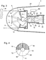
- FIG. 3 shows a schematic sectional view through the seeker 4 of the missile 2.
- the seeker 4 includes an optical system 18 with the outer optics 8, which includes the mirror 10, 12, and a detector optics 32, which forms the inner optics.
- the detector optics 32 comprises an arrangement of lenses for imaging an object 34 on a detector 36.
- the detector 36 is arranged in the search head 4 in a structurally fixed manner, ie it is immovably fixed relative to the outer skin 20 of the seeker head 4.
- the detector optics 32 is arranged in a rolling frame 38, which is movably supported by bearings 42 and rotatable relative to structural elements 40 about the roll axis 16.
- a pitch frame 44 is movably supported in bearings 46 and is also rotatable about the pitch axis 14 around the pitch axis 14 in addition to being rotatable. This ensures a two-dimensional mobility of the outer optics 8 in a hemisphere-sized angular range.
- prisms 48, 50 radiation trapped by the outer optics 8 is directed to the detector optics 32, with the prism 50 mounted in the rolling frame 38 and the prism 48 in the pitch frame 44.
- the prisms 48, 50 mirrors are conceivable.
- the detector optics 32 has a zone 54 in which the rays of the beam path 42 are almost parallel to each other, which for clarity in FIG. 2 not shown.
- a diaphragm 56 is arranged, which is introduced by a drive 58 - controlled by a control means 60 - in the beam path 52 of the optical system 18 in the direction of the arrow 62 shown.
- a control means 60 in the beam path 52 of the optical system 18 in the direction of the arrow 62 shown.
- an arrangement between the detector optics 32 and the detector 36 is conceivable, for example as shown by the dashed line 64.
- the diaphragm 56 can be moved into and out of the beam path 52 by the control unit 60 during the flight of the missile 2, the control means 60 being prepared by means of software to move the diaphragm 56 into the beam path 52 in dependence on a predetermined parameter.
- the screen 56 can be introduced up to the middle of the beam path 52 so that half the cross-sectional area of the beam path 52 at the location of the screen 56 is masked out by the screen 56 becomes. An undesired reversion of the optics 18 in the direction of the object 34 can be suppressed thereby. How far the control means 60 introduces the diaphragm 56 into the beam path 52 can also be made dependent on a parameter, for example a progression of the squint angle over time.
- FIG. 4 shows a cross section through the beam path 52 at the location of the diaphragm 56.
- a central portion 66 of the beam path 52 remains radiation-free due to the shadowing by the mirror 12.
- radiation is transmitted from the outer optics 8 to the detector 36, while in a diaphragm region 70 the radiation of the beam path 52 is masked out by the diaphragm 56.
- the central portion 66 can be partially covered by the aperture 56.
- the diaphragm 56 is arranged in the beam path 52 such that a front edge 72 pointing in the beam path 52 runs perpendicular to the pitch axis 14.
- the front edge 72 is arranged perpendicular to both the pitch axis 14 and the roll axis 16. From the perspective of FIG. 3 the leading edge 62 thus runs perpendicular to the plane of the paper.
- FIG. 5 Six small graphics interpret the course of shading 74 by the structurally solid element 20 during a pivoting movement of the outer optics 8 by 180 ° the pitch axis 14 at.
- the outer optics 8 and with it the input aperture is pivoted by 90 ° to the roll axis 16, the squint angle ⁇ is thus 90 °.
- the structurally solid element 20 is half of the beam path 42 in the region of the diaphragm 46 is shadowed, the shading 64 is thus half the cross section of the beam path 52 at the location of the diaphragm 56.
- the squint angle ⁇ is about 70 °.
- the shading 74 is thus somewhat reduced, as shown on the lower part of the second graph.
- FIG. 5 It can also be seen that the shadowing 28 rotates by the structurally fixed element 20 with a rotation of the input aperture 22 about the pitch axis 14 in the region of the diaphragm 56 and also to the detector 36 with the squint angle ⁇ .
- a pitching motion of, for example, 90 ° an image of the object 34 on the detector 36 and also the shading 28 in the region of the diaphragm 56 thus rotate by the same angular amount.
- the shading 28 moves at the in FIG. 5 shown representation with increasing squint angle ⁇ always from top to bottom in the beam path 42, regardless of whether the input aperture 22 is pivoted to the right or left.
- FIG. 6 shows an aperture wheel 76 with three apertures 78, 80, 82, each consisting of different spectral filters. In this way, for example, only a long-wave, a long and medium wave or only a short-wave spectral range are filtered out, for example, depending on detected target radiation.
- the aperture wheel 76 is rotatable about an axis of rotation 84 of, for example, the drive 58, so that one of the diaphragms 78, 80, 82 can be inserted into the beam path 52 in an arbitrary manner.
- the front edges 72 of the apertures 78, 80, 82 are always aligned in the same direction in the beam path 52, namely perpendicular to the pitch axis 14th
- FIG. 7 shows a profile of the squint angle ⁇ of the entrance aperture 22 and outer optics 8 over time t.
- the missile 2 is launched by an aircraft in the direction of a target or the object 34.
- the outer optic 8 is already aligned with the target so that the squint angle ⁇ is not equal to zero and in the example FIG. 7 about 20 °.
- the squint angle ⁇ varies until the missile 2 hits its target, wherein the variation of the squint angle ⁇ increases with decreasing distance to the target, for example as a result of flight maneuvers of the target.
- a flight time t F is calculated from the start time t 0 to a calculated impact time t 2 .
- the target radiation has arithmetically reached twice the intensity over the distance as at the start time t 0 by the quadratic profile of the target radiation.
- the 30% - is the time of flight t F - or some other value.
- the retraction of the diaphragm 56 in the beam path 52 is controlled by the control means 60.
- the calculated impact time point t AR does not have to coincide with the actual impact time point t A , since it is unknown and can be significantly behind the calculated impact time t AR due to flight maneuvers of the target. However, this is harmless for the retraction of the diaphragm 56, since the first approach phase of the missile 2 to the target during the first 30% of the calculated flight time t F in Essentially linear, and make maneuvers or other disturbances noticeable only on further approach of the missile to the target.
- Another possibility is to monitor the squint angle ⁇ over time and to control the shutter speed t 2 as a function of the course of the squint angle ⁇ .
- shading occurs only at a squint angle ⁇ above 50 °.
- the diaphragm 56 can be retracted into the beam path 52, but expediently only after completion of at least 30% of the flight time t f in order to reliably avoid loss of the target.
- FIG. 7 shading occurs only at a squint angle ⁇ above 50 °.
- the aperture time t 2 at which the aperture 56 is retracted into the beam path 52, from the duration of the squint angle ⁇ above 50 ° - or another Schielwinkelgrenzwert - during a predetermined time interval, for example, 10 seconds determined.
- a predetermined time interval for example, 10 seconds determined.
- this predetermined duration is exceeded and the diaphragm 56 is retracted. From this time t 2 , as well as the previously described time t 1 , the diaphragm 56 remains in the beam path 52 regardless of how the squint angle ⁇ behaves in the further course.
- FIG. 8 Shown is a highly smoothed course of the incident radiation 36 on the detector 86 as a function of its wavelength ⁇ .
- the radiation 86 comprises, for example, a portion of structural radiation 88 which is radiated from the highly heated dome 6 and other elements 20 of the missile 2 and which increases in intensity with increasing wavelength.
- a portion of background radiation 90 which for the sake of simplicity is assumed to be constant over the wavelength, is added to this structure radiation 88, so that the radiation 86 is composed of the sum of the structure radiation 88 and the background radiation 90.
- a very small amount of target radiation 92 is added to the radiation 86 in a relatively narrow spectral interval.
- the structure radiation 88 fluctuates very strongly, so that the radiation 86 very rapidly saturates the detector 36, which is in FIG. 7 can be achieved as 100%.
- a strong fluctuation of the radiation 86 for example, a radiation fluctuation .DELTA.I above a limit of z. B. 25% of the detector saturation radiation, wherein the radiation fluctuation .DELTA.I over the entire completed flight time or over a different time interval can be used, the aperture 56 is retracted into the beam path 52.
- the aperture 78 retracted which is designed as a spectral filter for filtering long-wave infrared radiation.
- the radiation 86 is thereby reduced, as shown by dashed lines around the cut-off wavelength ⁇ 1 from which the spectral filter of the aperture 78 filters. A fluctuation of the structure radiation 88 and thus the total radiation 86 is thereby greatly reduced and image errors are reduced.
Landscapes
- Physics & Mathematics (AREA)
- Engineering & Computer Science (AREA)
- General Physics & Mathematics (AREA)
- Optics & Photonics (AREA)
- General Engineering & Computer Science (AREA)
- Combustion & Propulsion (AREA)
- Chemical & Material Sciences (AREA)
- Electromagnetism (AREA)
- Toxicology (AREA)
- Health & Medical Sciences (AREA)
- Remote Sensing (AREA)
- Radar, Positioning & Navigation (AREA)
- Astronomy & Astrophysics (AREA)
- Spectroscopy & Molecular Physics (AREA)
- Aiming, Guidance, Guns With A Light Source, Armor, Camouflage, And Targets (AREA)
- Optical Radar Systems And Details Thereof (AREA)
- Length Measuring Devices By Optical Means (AREA)
Claims (14)
- Système optique pour un missile (2) comprenant une optique (18) servant à représenter un objet (34) au moyen d'un trajet de rayon (52) dans un plan de représentation, l'optique (18) possédant une optique externe (8) montée à rotation autour d'un axe de roulis (16) et un axe de tangage (14) du missile (2) ainsi qu'une optique interne (32) et l'une des extrémités du trajet de rayon (52) se trouvant en position structurale fixe dans le missile (2),
caractérisé
par un diaphragme (56, 78, 80, 82) qui peut être introduit dans le trajet de rayon (52) pendant un vol du missile (2), un moyen de commande (60) et un mécanisme d'entraînement (58) commandé par le moyen de commande (60),
le diaphragme (56, 78, 80, 82) pouvant être introduit dans le trajet de rayon (52) par le mécanisme d'entraînement (58) commandé par le moyen de commande (60), et le moyen de commande (60) étant configuré pour déplacer le diaphragme (56, 78, 80, 82) à l'intérieur du trajet de rayon (52) en fonction d'un paramètre prédéfini en vue de masquer une projection d'ombre (28) dans le trajet de rayon (52), provoquée par un élément (20) du missile (2), lors d'une direction de visée de l'optique externe (8) basculée par rapport à l'axe de roulis (16). - Système optique selon la revendication 1,
caractérisé en ce que le diaphragme (56, 78, 80, 82) amené dans le trajet de rayon est disposé de telle sorte que lors d'un mouvement de l'optique externe (8) autour de l'axe de tangage (14), il recouvre la projection d'ombre (28) de l'élément (20) structural fixe dans une plage angulaire d'au moins 150°. - Système optique selon la revendication 1 ou 2,
caractérisé en ce que l'optique externe (8) peut tourner par rapport au diaphragme (56, 78, 80, 82) autour de l'axe de tangage (14). - Système optique selon l'une des revendications précédentes, caractérisé en ce que le diaphragme (56, 78, 80, 82) peut tourner autour de l'axe de roulis (16).
- Système optique selon l'une des revendications précédentes, caractérisé en ce que le diaphragme (56, 78, 80, 82) peut tourner autour de l'axe de roulis (16) conjointement avec l'optique interne (32).
- Système optique selon l'une des revendications précédentes, caractérisé en ce que le diaphragme (56, 78, 80, 82) peut être introduit de manière asymétrique dans le trajet de rayon (52).
- Système optique selon l'une des revendications précédentes, caractérisé en ce que le diaphragme (56, 78, 80, 82) est pourvu d'une arête droite (72) ayant une direction d'arête qui, lors d'un mouvement du diaphragme (56, 78, 80, 82) vers l'intérieur du trajet de rayon (52), est introduite dans le trajet de rayon (52) en tant qu'arête avant (72), la direction d'arête étant orientée perpendiculairement à l'axe de tangage (14) dans chaque position de l'optique externe (8).
- Système optique selon l'une des revendications précédentes, caractérisé en ce que le diaphragme (78, 80, 82) possède un filtre spectral partiellement transmissif.
- Système optique selon l'une des revendications précédentes, caractérisé en ce que le diaphragme comporte un porte-diaphragme (76) comprenant plusieurs éléments de diaphragme réalisés sous la forme de filtres spectraux différents, lesquels peuvent être introduits de manière sélective dans le trajet de rayon (52).
- Système optique selon la revendication 9,
caractérisé en ce que la sélection du filtre spectral s'effectue en fonction d'une fréquence d'un rayonnement cible. - Procédé de représentation d'un objet (34) au moyen d'un trajet de rayon (52) d'une optique (18) d'un missile (2) dans un plan de représentation, l'optique (18) possédant une optique externe (8) montée à rotation autour d'un axe de roulis (16) et un axe de tangage (14) du missile (2) ainsi qu'une optique interne (32) et l'une des extrémités du trajet de rayon (52) se trouvant en position structurale fixe dans le missile (2),
caractérisé en ce que
pendant un vol du missile (2), un diaphragme (56, 78, 80, 82) est introduit dans le trajet de rayon (52) par un mécanisme d'entraînement (58) commandé par un moyen de commande (60) afin de masquer une projection d'ombre (28) d'un élément (20) structural fixe du missile (2) dans le trajet de rayon (52) en présence d'un angle de strabisme (α) important de l'optique (18), le moyen de commande (60) étant configuré pour déplacer le diaphragme (56, 78, 80, 82) à l'intérieur du trajet de rayon (52) en fonction d'un paramètre prédéfini. - Procédé selon la revendication 11, caractérisé en ce que le temps de vol (tF) jusqu'à une cible visée est calculé et l'introduction du diaphragme (56, 78, 80, 82) est commandée à l'aide d'une minuterie après écoulement d'au moins 25 % du temps de vol (tF) calculé jusqu'à la cible visée.
- Procédé selon la revendication 11 ou 12,
caractérisé en ce que pendant le vol, une intensité d'un rayonnement incident sur un détecteur (32) est surveillée et l'introduction du diaphragme (56, 78, 80, 82) s'effectue en présence d'une fluctuation dans le temps de l'intensité supérieure à une valeur limite prédéfinie. - Procédé selon l'une des revendications 11 à 13,
caractérisé en ce que pendant le vol, un angle de strabisme (α) de l'optique externe (8) est surveillé et l'introduction du diaphragme (56, 78, 80, 82) s'effectue en fonction de la courbe de l'angle de strabisme (α) pendant un temps donné.
Applications Claiming Priority (1)
| Application Number | Priority Date | Filing Date | Title |
|---|---|---|---|
| DE102009029895.9A DE102009029895B4 (de) | 2009-06-23 | 2009-06-23 | Optisches System für einen Flugkörper und Verfahren zum Abbilden eines Gegenstands |
Publications (2)
| Publication Number | Publication Date |
|---|---|
| EP2267397A1 EP2267397A1 (fr) | 2010-12-29 |
| EP2267397B1 true EP2267397B1 (fr) | 2018-08-22 |
Family
ID=42768060
Family Applications (1)
| Application Number | Title | Priority Date | Filing Date |
|---|---|---|---|
| EP10006167.0A Not-in-force EP2267397B1 (fr) | 2009-06-23 | 2010-06-15 | Système optique pour un objet volant et procédé de représentation d'un objet |
Country Status (5)
| Country | Link |
|---|---|
| US (1) | US8354626B2 (fr) |
| EP (1) | EP2267397B1 (fr) |
| DE (1) | DE102009029895B4 (fr) |
| IL (1) | IL206506A (fr) |
| ZA (1) | ZA201004353B (fr) |
Families Citing this family (11)
| Publication number | Priority date | Publication date | Assignee | Title |
|---|---|---|---|---|
| DE102010055492B4 (de) * | 2010-12-15 | 2020-08-06 | Diehl Defence Gmbh & Co. Kg | Cassegrainoptik |
| DE102011104023B4 (de) | 2011-06-11 | 2019-07-25 | Diehl Defence Gmbh & Co. Kg | Optische Vorrichtung für einen Suchkopf für einen Lenkflugkörper und Suchkopf für einen Lenkflugkörper |
| DE102011104021A1 (de) | 2011-06-11 | 2012-12-13 | Diehl Bgt Defence Gmbh & Co. Kg | Optische Vorrichtung |
| DE102012009172A1 (de) * | 2012-05-08 | 2013-11-14 | Diehl Bgt Defence Gmbh & Co. Kg | Suchkopf für einen Flugkörper |
| US9207053B2 (en) * | 2013-06-21 | 2015-12-08 | Rosemount Aerospace Inc. | Harmonic shuttered seeker |
| US10996104B2 (en) * | 2017-08-23 | 2021-05-04 | Rosemount Aerospace Inc. | Terminal-imaging seeker using a spatial light modulator based coded-aperture mask |
| US10712129B2 (en) * | 2017-08-23 | 2020-07-14 | Rosemount Aerospace Inc. | Terminal-imaging seeker with software defined optics |
| FR3087546B1 (fr) | 2018-10-23 | 2023-03-03 | Safran Electronics & Defense | Ensemble optique de collecte de rayonnement pour dispositif autodirecteur de guidage d'engin autopropulse |
| US11371806B2 (en) * | 2019-08-05 | 2022-06-28 | Bae Systems Information And Electronic Systems Integration Inc. | Midbody camera/sensor navigation and automatic target recognition |
| FR3117203B1 (fr) * | 2020-12-03 | 2022-12-09 | Thales Sa | Système optronique omnidirectionnel |
| DE102021005406B4 (de) | 2021-10-30 | 2023-06-22 | Diehl Defence Gmbh & Co. Kg | Optische Vorrichtung zur Erfassung einer Objektszene und Suchkopf |
Family Cites Families (24)
| Publication number | Priority date | Publication date | Assignee | Title |
|---|---|---|---|---|
| US4091412A (en) * | 1967-12-01 | 1978-05-23 | The United States Of America As Represented By The Secretary Of The Army | Target designation system |
| US4131248A (en) * | 1968-03-13 | 1978-12-26 | E-Systems, Inc. | Optical range resolution system |
| US3837733A (en) * | 1968-12-11 | 1974-09-24 | Martin Marietta Corp | Shiftable scanner aperture |
| US3807659A (en) * | 1972-06-16 | 1974-04-30 | Us Army | Laser protection mechanism |
| FR2356152A1 (fr) * | 1976-06-25 | 1978-01-20 | Thomson Csf | Systeme optoelectrique de localisation angulaire d'un objet lumineux |
| DE2813032C1 (de) * | 1978-03-25 | 1991-02-21 | Messerschmitt Boelkow Blohm | Gleitgeschoss |
| US4784350A (en) * | 1979-02-12 | 1988-11-15 | The United States Of America As Represented By The Secretary Of The Navy | Passive step trimmer for a maneuvering re-entry body (U) |
| FR2453418A1 (fr) * | 1979-04-06 | 1980-10-31 | Thomson Csf | Dispositif optoelectrique de localisation de source lumineuse ponctuelle et systemes comportant de tels dispositifs |
| US4386848A (en) * | 1980-08-11 | 1983-06-07 | Martin Marietta Corporation | Optical target tracking and designating system |
| DE3616796C1 (de) | 1986-05-17 | 1987-07-09 | Messerschmitt Boelkow Blohm | Optoelektronisches Ortungssystem |
| DE3807725A1 (de) * | 1988-03-09 | 1989-09-21 | Bodenseewerk Geraetetech | Endphasengelenktes geschoss |
| US5138162A (en) * | 1988-12-16 | 1992-08-11 | The United States Of America As Represented By The Secretary Of The Army | Method and apparatus for producing enhanced images of curved thermal objects |
| JPH03274395A (ja) * | 1990-03-23 | 1991-12-05 | Mitsubishi Heavy Ind Ltd | 赤外線シーカー |
| US5323987A (en) * | 1993-03-04 | 1994-06-28 | The Boeing Company | Missile seeker system and method |
| IL107830A (en) * | 1993-12-01 | 1998-07-15 | Israel State | Controlled scanner head missile |
| IL134189A0 (en) * | 2000-01-24 | 2001-04-30 | Israel State | Device |
| US6267039B1 (en) * | 2000-02-09 | 2001-07-31 | The United States Of America As Represented By The Secretary Of The Air Force | Aircraft missile-hit survivability using infrared lamp and sacrificial support structure |
| DE10153094A1 (de) * | 2001-10-30 | 2003-05-15 | Bodenseewerk Geraetetech | Optischer Sensor mit einem Sensorstrahlengang und einem parallel zu der optischen Achse des Sensorstrahlenganges emittierenden Laserstrahler |
| DE10232259A1 (de) * | 2002-07-16 | 2004-02-05 | BODENSEEWERK GERäTETECHNIK GMBH | Sucheranordnung zum Beobachten eines großen Raumwinkels mittels eines bildauflösenden Detektors |
| EP1586195B1 (fr) * | 2003-01-21 | 2006-05-17 | Diehl BGT Defence GmbH & Co.KG | Dispositif de detection d'une scene objet |
| DE10313136B4 (de) * | 2003-03-29 | 2017-05-11 | Diehl Defence Gmbh & Co. Kg | Suchkopf mit Nick-Gier-Innenkardansystem |
| DE102007019101B4 (de) * | 2007-04-23 | 2013-05-29 | Diehl Bgt Defence Gmbh & Co. Kg | Vorrichtung zur Erfassung einer Objektszene |
| DE102007030880B4 (de) * | 2007-07-03 | 2013-05-29 | Diehl Bgt Defence Gmbh & Co. Kg | Vorrichtung zur Erfassung einer Objektszene |
| DE102007053730B4 (de) * | 2007-11-10 | 2013-11-07 | Diehl Bgt Defence Gmbh & Co. Kg | Zielführungsvorrichtung |
-
2009
- 2009-06-23 DE DE102009029895.9A patent/DE102009029895B4/de not_active Expired - Fee Related
-
2010
- 2010-06-15 EP EP10006167.0A patent/EP2267397B1/fr not_active Not-in-force
- 2010-06-20 IL IL206506A patent/IL206506A/en not_active IP Right Cessation
- 2010-06-21 ZA ZA2010/04353A patent/ZA201004353B/en unknown
- 2010-06-23 US US12/821,635 patent/US8354626B2/en not_active Expired - Fee Related
Non-Patent Citations (1)
| Title |
|---|
| None * |
Also Published As
| Publication number | Publication date |
|---|---|
| DE102009029895B4 (de) | 2018-01-25 |
| EP2267397A1 (fr) | 2010-12-29 |
| ZA201004353B (en) | 2011-04-28 |
| IL206506A (en) | 2014-03-31 |
| IL206506A0 (en) | 2010-12-30 |
| DE102009029895A1 (de) | 2011-01-05 |
| US8354626B2 (en) | 2013-01-15 |
| US20100327105A1 (en) | 2010-12-30 |
Similar Documents
| Publication | Publication Date | Title |
|---|---|---|
| EP2267397B1 (fr) | Système optique pour un objet volant et procédé de représentation d'un objet | |
| EP2533003B1 (fr) | Dispositif optique destiné au guidage du rayonnement d'une scène sur un détecteur | |
| DE2819938C2 (de) | Elektrooptisches Fernlenksystem für passive Geschosse | |
| DE69727102T2 (de) | Integrierte hochauflösende Rundum-Sensoroptik | |
| DE102004003773B4 (de) | Optisches System und Verfahren zur Aufnahme einer Anzahl von Bildern | |
| DE1132742B (de) | Zielfernrohr | |
| EP3514477A1 (fr) | Système et procédé de perturbation d'une détection de cibles | |
| DE3247261C2 (fr) | ||
| EP2161533A1 (fr) | Système de détection d'objet doté d'un système d'imagerie | |
| EP2533004B1 (fr) | Dispositif optique | |
| DE19904687A1 (de) | Richtbare Teleskopanordnung | |
| EP2954364B1 (fr) | Procédé et dispositif destinés à recevoir et traiter les signaux optiques en provenance d'un objet volumineux | |
| DE2655520A1 (de) | Verfahren und vorrichtung zur detektion und identifizierung eines hubschraubers | |
| EP0009071B1 (fr) | Théodolite pour la poursuite d'un objet volant avec caméra de télévision incorporée dans le télescope | |
| DE102005006726A1 (de) | Verfahren und Vorrichtung zum Entdecken von optischen Systemen in einem Geländebereich | |
| DE69111032T2 (de) | Selbst kalibrierendes optronisches System zur infraroten Beobachtung sowie ein richtungsweisender Korb ein solches System enthaltend. | |
| DE3630701A1 (de) | Optisches visiergeraet fuer helikopter | |
| DE102010006661B4 (de) | Verfahren und Vorrichtung zum Abbilden einer Umgebung auf eine Detektoreinrichtung | |
| DE102019006717A1 (de) | Laserwaffensystem und Verfahren zur Bestrahlung eines Ziels | |
| EP2466246B1 (fr) | Optique cassegrain | |
| DE102010006662B4 (de) | Vorrichtung und Verfahren zum Abbilden einer Umgebung auf eine Detektoreinrichtung | |
| DE102010055492B4 (de) | Cassegrainoptik | |
| DE102017008711B4 (de) | Verfahren zum Steuern eines Flugkörpers | |
| DE2851393C2 (de) | IR-optisches Visier- und Lenkgerät für Flugkörper | |
| CH625335A5 (en) | Optical target-tracking unit |
Legal Events
| Date | Code | Title | Description |
|---|---|---|---|
| PUAI | Public reference made under article 153(3) epc to a published international application that has entered the european phase |
Free format text: ORIGINAL CODE: 0009012 |
|
| AK | Designated contracting states |
Kind code of ref document: A1 Designated state(s): AL AT BE BG CH CY CZ DE DK EE ES FI FR GB GR HR HU IE IS IT LI LT LU LV MC MK MT NL NO PL PT RO SE SI SK SM TR |
|
| AX | Request for extension of the european patent |
Extension state: BA ME RS |
|
| 17P | Request for examination filed |
Effective date: 20110525 |
|
| STAA | Information on the status of an ep patent application or granted ep patent |
Free format text: STATUS: EXAMINATION IS IN PROGRESS |
|
| 17Q | First examination report despatched |
Effective date: 20161222 |
|
| RAP1 | Party data changed (applicant data changed or rights of an application transferred) |
Owner name: DIEHL DEFENCE GMBH & CO. KG |
|
| GRAP | Despatch of communication of intention to grant a patent |
Free format text: ORIGINAL CODE: EPIDOSNIGR1 |
|
| STAA | Information on the status of an ep patent application or granted ep patent |
Free format text: STATUS: GRANT OF PATENT IS INTENDED |
|
| RIC1 | Information provided on ipc code assigned before grant |
Ipc: G02B 13/14 20060101ALI20180215BHEP Ipc: G02B 17/06 20060101ALI20180215BHEP Ipc: G02B 26/10 20060101ALI20180215BHEP Ipc: G02B 26/02 20060101ALI20180215BHEP Ipc: G01S 3/786 20060101ALI20180215BHEP Ipc: G01S 3/781 20060101ALI20180215BHEP Ipc: F41G 7/22 20060101AFI20180215BHEP Ipc: G02B 26/00 20060101ALI20180215BHEP |
|
| INTG | Intention to grant announced |
Effective date: 20180316 |
|
| GRAS | Grant fee paid |
Free format text: ORIGINAL CODE: EPIDOSNIGR3 |
|
| GRAA | (expected) grant |
Free format text: ORIGINAL CODE: 0009210 |
|
| STAA | Information on the status of an ep patent application or granted ep patent |
Free format text: STATUS: THE PATENT HAS BEEN GRANTED |
|
| AK | Designated contracting states |
Kind code of ref document: B1 Designated state(s): AL AT BE BG CH CY CZ DK EE ES FI FR GB GR HR HU IE IS IT LI LT LU LV MC MK MT NL NO PL PT RO SE SI SK SM TR |
|
| RBV | Designated contracting states (corrected) |
Designated state(s): AL AT BE BG CH CY CZ DK EE ES FI FR GB GR HR HU IE IS IT LI LT LU LV MC MK MT NL NO PL PT RO SE SI SK SM TR |
|
| REG | Reference to a national code |
Ref country code: GB Ref legal event code: FG4D Free format text: NOT ENGLISH Ref country code: DE Ref legal event code: R108 |
|
| REG | Reference to a national code |
Ref country code: CH Ref legal event code: EP |
|
| REG | Reference to a national code |
Ref country code: AT Ref legal event code: REF Ref document number: 1033005 Country of ref document: AT Kind code of ref document: T Effective date: 20180915 |
|
| REG | Reference to a national code |
Ref country code: IE Ref legal event code: FG4D Free format text: LANGUAGE OF EP DOCUMENT: GERMAN |
|
| REG | Reference to a national code |
Ref country code: SE Ref legal event code: TRGR |
|
| REG | Reference to a national code |
Ref country code: NL Ref legal event code: MP Effective date: 20180822 |
|
| REG | Reference to a national code |
Ref country code: LT Ref legal event code: MG4D |
|
| PG25 | Lapsed in a contracting state [announced via postgrant information from national office to epo] |
Ref country code: NL Free format text: LAPSE BECAUSE OF FAILURE TO SUBMIT A TRANSLATION OF THE DESCRIPTION OR TO PAY THE FEE WITHIN THE PRESCRIBED TIME-LIMIT Effective date: 20180822 Ref country code: IS Free format text: LAPSE BECAUSE OF FAILURE TO SUBMIT A TRANSLATION OF THE DESCRIPTION OR TO PAY THE FEE WITHIN THE PRESCRIBED TIME-LIMIT Effective date: 20181222 Ref country code: BG Free format text: LAPSE BECAUSE OF FAILURE TO SUBMIT A TRANSLATION OF THE DESCRIPTION OR TO PAY THE FEE WITHIN THE PRESCRIBED TIME-LIMIT Effective date: 20181122 Ref country code: NO Free format text: LAPSE BECAUSE OF FAILURE TO SUBMIT A TRANSLATION OF THE DESCRIPTION OR TO PAY THE FEE WITHIN THE PRESCRIBED TIME-LIMIT Effective date: 20181122 Ref country code: GR Free format text: LAPSE BECAUSE OF FAILURE TO SUBMIT A TRANSLATION OF THE DESCRIPTION OR TO PAY THE FEE WITHIN THE PRESCRIBED TIME-LIMIT Effective date: 20181123 Ref country code: FI Free format text: LAPSE BECAUSE OF FAILURE TO SUBMIT A TRANSLATION OF THE DESCRIPTION OR TO PAY THE FEE WITHIN THE PRESCRIBED TIME-LIMIT Effective date: 20180822 Ref country code: LT Free format text: LAPSE BECAUSE OF FAILURE TO SUBMIT A TRANSLATION OF THE DESCRIPTION OR TO PAY THE FEE WITHIN THE PRESCRIBED TIME-LIMIT Effective date: 20180822 |
|
| PG25 | Lapsed in a contracting state [announced via postgrant information from national office to epo] |
Ref country code: HR Free format text: LAPSE BECAUSE OF FAILURE TO SUBMIT A TRANSLATION OF THE DESCRIPTION OR TO PAY THE FEE WITHIN THE PRESCRIBED TIME-LIMIT Effective date: 20180822 Ref country code: ES Free format text: LAPSE BECAUSE OF FAILURE TO SUBMIT A TRANSLATION OF THE DESCRIPTION OR TO PAY THE FEE WITHIN THE PRESCRIBED TIME-LIMIT Effective date: 20180822 Ref country code: AL Free format text: LAPSE BECAUSE OF FAILURE TO SUBMIT A TRANSLATION OF THE DESCRIPTION OR TO PAY THE FEE WITHIN THE PRESCRIBED TIME-LIMIT Effective date: 20180822 Ref country code: LV Free format text: LAPSE BECAUSE OF FAILURE TO SUBMIT A TRANSLATION OF THE DESCRIPTION OR TO PAY THE FEE WITHIN THE PRESCRIBED TIME-LIMIT Effective date: 20180822 |
|
| PG25 | Lapsed in a contracting state [announced via postgrant information from national office to epo] |
Ref country code: RO Free format text: LAPSE BECAUSE OF FAILURE TO SUBMIT A TRANSLATION OF THE DESCRIPTION OR TO PAY THE FEE WITHIN THE PRESCRIBED TIME-LIMIT Effective date: 20180822 Ref country code: IT Free format text: LAPSE BECAUSE OF FAILURE TO SUBMIT A TRANSLATION OF THE DESCRIPTION OR TO PAY THE FEE WITHIN THE PRESCRIBED TIME-LIMIT Effective date: 20180822 Ref country code: CZ Free format text: LAPSE BECAUSE OF FAILURE TO SUBMIT A TRANSLATION OF THE DESCRIPTION OR TO PAY THE FEE WITHIN THE PRESCRIBED TIME-LIMIT Effective date: 20180822 Ref country code: PL Free format text: LAPSE BECAUSE OF FAILURE TO SUBMIT A TRANSLATION OF THE DESCRIPTION OR TO PAY THE FEE WITHIN THE PRESCRIBED TIME-LIMIT Effective date: 20180822 Ref country code: EE Free format text: LAPSE BECAUSE OF FAILURE TO SUBMIT A TRANSLATION OF THE DESCRIPTION OR TO PAY THE FEE WITHIN THE PRESCRIBED TIME-LIMIT Effective date: 20180822 |
|
| PG25 | Lapsed in a contracting state [announced via postgrant information from national office to epo] |
Ref country code: SK Free format text: LAPSE BECAUSE OF FAILURE TO SUBMIT A TRANSLATION OF THE DESCRIPTION OR TO PAY THE FEE WITHIN THE PRESCRIBED TIME-LIMIT Effective date: 20180822 Ref country code: DK Free format text: LAPSE BECAUSE OF FAILURE TO SUBMIT A TRANSLATION OF THE DESCRIPTION OR TO PAY THE FEE WITHIN THE PRESCRIBED TIME-LIMIT Effective date: 20180822 Ref country code: SM Free format text: LAPSE BECAUSE OF FAILURE TO SUBMIT A TRANSLATION OF THE DESCRIPTION OR TO PAY THE FEE WITHIN THE PRESCRIBED TIME-LIMIT Effective date: 20180822 |
|
| PLBE | No opposition filed within time limit |
Free format text: ORIGINAL CODE: 0009261 |
|
| STAA | Information on the status of an ep patent application or granted ep patent |
Free format text: STATUS: NO OPPOSITION FILED WITHIN TIME LIMIT |
|
| 26N | No opposition filed |
Effective date: 20190523 |
|
| PG25 | Lapsed in a contracting state [announced via postgrant information from national office to epo] |
Ref country code: SI Free format text: LAPSE BECAUSE OF FAILURE TO SUBMIT A TRANSLATION OF THE DESCRIPTION OR TO PAY THE FEE WITHIN THE PRESCRIBED TIME-LIMIT Effective date: 20180822 |
|
| PGFP | Annual fee paid to national office [announced via postgrant information from national office to epo] |
Ref country code: SE Payment date: 20190619 Year of fee payment: 10 Ref country code: FR Payment date: 20190619 Year of fee payment: 10 |
|
| PGFP | Annual fee paid to national office [announced via postgrant information from national office to epo] |
Ref country code: GB Payment date: 20190619 Year of fee payment: 10 |
|
| PG25 | Lapsed in a contracting state [announced via postgrant information from national office to epo] |
Ref country code: MC Free format text: LAPSE BECAUSE OF FAILURE TO SUBMIT A TRANSLATION OF THE DESCRIPTION OR TO PAY THE FEE WITHIN THE PRESCRIBED TIME-LIMIT Effective date: 20180822 |
|
| REG | Reference to a national code |
Ref country code: CH Ref legal event code: PL |
|
| REG | Reference to a national code |
Ref country code: BE Ref legal event code: MM Effective date: 20190630 |
|
| PG25 | Lapsed in a contracting state [announced via postgrant information from national office to epo] |
Ref country code: TR Free format text: LAPSE BECAUSE OF FAILURE TO SUBMIT A TRANSLATION OF THE DESCRIPTION OR TO PAY THE FEE WITHIN THE PRESCRIBED TIME-LIMIT Effective date: 20180822 |
|
| PG25 | Lapsed in a contracting state [announced via postgrant information from national office to epo] |
Ref country code: IE Free format text: LAPSE BECAUSE OF NON-PAYMENT OF DUE FEES Effective date: 20190615 |
|
| PG25 | Lapsed in a contracting state [announced via postgrant information from national office to epo] |
Ref country code: LI Free format text: LAPSE BECAUSE OF NON-PAYMENT OF DUE FEES Effective date: 20190630 Ref country code: CH Free format text: LAPSE BECAUSE OF NON-PAYMENT OF DUE FEES Effective date: 20190630 Ref country code: LU Free format text: LAPSE BECAUSE OF NON-PAYMENT OF DUE FEES Effective date: 20190615 Ref country code: BE Free format text: LAPSE BECAUSE OF NON-PAYMENT OF DUE FEES Effective date: 20190630 |
|
| PG25 | Lapsed in a contracting state [announced via postgrant information from national office to epo] |
Ref country code: PT Free format text: LAPSE BECAUSE OF FAILURE TO SUBMIT A TRANSLATION OF THE DESCRIPTION OR TO PAY THE FEE WITHIN THE PRESCRIBED TIME-LIMIT Effective date: 20181222 |
|
| REG | Reference to a national code |
Ref country code: AT Ref legal event code: MM01 Ref document number: 1033005 Country of ref document: AT Kind code of ref document: T Effective date: 20190615 |
|
| PG25 | Lapsed in a contracting state [announced via postgrant information from national office to epo] |
Ref country code: AT Free format text: LAPSE BECAUSE OF NON-PAYMENT OF DUE FEES Effective date: 20190615 |
|
| GBPC | Gb: european patent ceased through non-payment of renewal fee |
Effective date: 20200615 |
|
| PG25 | Lapsed in a contracting state [announced via postgrant information from national office to epo] |
Ref country code: GB Free format text: LAPSE BECAUSE OF NON-PAYMENT OF DUE FEES Effective date: 20200615 Ref country code: FR Free format text: LAPSE BECAUSE OF NON-PAYMENT OF DUE FEES Effective date: 20200630 |
|
| PG25 | Lapsed in a contracting state [announced via postgrant information from national office to epo] |
Ref country code: CY Free format text: LAPSE BECAUSE OF FAILURE TO SUBMIT A TRANSLATION OF THE DESCRIPTION OR TO PAY THE FEE WITHIN THE PRESCRIBED TIME-LIMIT Effective date: 20180822 Ref country code: SE Free format text: LAPSE BECAUSE OF NON-PAYMENT OF DUE FEES Effective date: 20200616 |
|
| PG25 | Lapsed in a contracting state [announced via postgrant information from national office to epo] |
Ref country code: MT Free format text: LAPSE BECAUSE OF FAILURE TO SUBMIT A TRANSLATION OF THE DESCRIPTION OR TO PAY THE FEE WITHIN THE PRESCRIBED TIME-LIMIT Effective date: 20180822 Ref country code: HU Free format text: LAPSE BECAUSE OF FAILURE TO SUBMIT A TRANSLATION OF THE DESCRIPTION OR TO PAY THE FEE WITHIN THE PRESCRIBED TIME-LIMIT; INVALID AB INITIO Effective date: 20100615 |
|
| REG | Reference to a national code |
Ref country code: SE Ref legal event code: EUG |
|
| PG25 | Lapsed in a contracting state [announced via postgrant information from national office to epo] |
Ref country code: MK Free format text: LAPSE BECAUSE OF FAILURE TO SUBMIT A TRANSLATION OF THE DESCRIPTION OR TO PAY THE FEE WITHIN THE PRESCRIBED TIME-LIMIT Effective date: 20180822 |