EP2267337A2 - Antriebsanordnung für ein Fahrzeug - Google Patents
Antriebsanordnung für ein Fahrzeug Download PDFInfo
- Publication number
- EP2267337A2 EP2267337A2 EP10157472A EP10157472A EP2267337A2 EP 2267337 A2 EP2267337 A2 EP 2267337A2 EP 10157472 A EP10157472 A EP 10157472A EP 10157472 A EP10157472 A EP 10157472A EP 2267337 A2 EP2267337 A2 EP 2267337A2
- Authority
- EP
- European Patent Office
- Prior art keywords
- shaft
- drive pinion
- drive
- bearing
- motor shaft
- Prior art date
- Legal status (The legal status is an assumption and is not a legal conclusion. Google has not performed a legal analysis and makes no representation as to the accuracy of the status listed.)
- Granted
Links
Images
Classifications
-
- F—MECHANICAL ENGINEERING; LIGHTING; HEATING; WEAPONS; BLASTING
- F16—ENGINEERING ELEMENTS AND UNITS; GENERAL MEASURES FOR PRODUCING AND MAINTAINING EFFECTIVE FUNCTIONING OF MACHINES OR INSTALLATIONS; THERMAL INSULATION IN GENERAL
- F16D—COUPLINGS FOR TRANSMITTING ROTATION; CLUTCHES; BRAKES
- F16D1/00—Couplings for rigidly connecting two coaxial shafts or other movable machine elements
- F16D1/10—Quick-acting couplings in which the parts are connected by simply bringing them together axially
-
- F—MECHANICAL ENGINEERING; LIGHTING; HEATING; WEAPONS; BLASTING
- F16—ENGINEERING ELEMENTS AND UNITS; GENERAL MEASURES FOR PRODUCING AND MAINTAINING EFFECTIVE FUNCTIONING OF MACHINES OR INSTALLATIONS; THERMAL INSULATION IN GENERAL
- F16H—GEARING
- F16H57/00—General details of gearing
- F16H57/02—Gearboxes; Mounting gearing therein
- F16H57/021—Shaft support structures, e.g. partition walls, bearing eyes, casing walls or covers with bearings
-
- F—MECHANICAL ENGINEERING; LIGHTING; HEATING; WEAPONS; BLASTING
- F16—ENGINEERING ELEMENTS AND UNITS; GENERAL MEASURES FOR PRODUCING AND MAINTAINING EFFECTIVE FUNCTIONING OF MACHINES OR INSTALLATIONS; THERMAL INSULATION IN GENERAL
- F16D—COUPLINGS FOR TRANSMITTING ROTATION; CLUTCHES; BRAKES
- F16D1/00—Couplings for rigidly connecting two coaxial shafts or other movable machine elements
- F16D1/10—Quick-acting couplings in which the parts are connected by simply bringing them together axially
- F16D2001/103—Quick-acting couplings in which the parts are connected by simply bringing them together axially the torque is transmitted via splined connections
Definitions
- the present invention relates to a drive arrangement for a vehicle according to the closer defined in the preamble of claim 1. Art.
- wheel drives are known with an electric motor and a gearbox.
- a drive pinion is mounted directly on a motor shaft and forms with a spur gear, a first gear stage for driving a transmission shaft of the transmission. This results in the disadvantage that during assembly of the motor, the running teeth of the drive pinion or the spur gear of the transmission can be damaged.
- the known drive comprises an electric motor whose motor shaft is mounted with a bearing point in a housing of the transmission of the drive.
- the disadvantage here is that due to the small bearing base in the gear housing, a misalignment of the drive pinion due to a production-related radial offset of the engine can be done.
- the present invention is based on the object to design a drive assembly of the type described above such that an over-determination of storage and a possible misalignment of the drive pinion while reducing costs is prevented.
- a drive arrangement for a vehicle is proposed with a transmission gear formed as a hollow shaft drive pinion, wherein an associated motor shaft rotatably received in the drive pinion or in the hollow shaft and wherein the drive pinion is mounted on the motor side via a roller bearing acting as a bearing and radially over an axially displaceable hub shaft connection is supported on the motor shaft.
- the bearing of the drive pinion is realized via the designed as a fixed bearing bearings, over-determination during storage and a misalignment of the drive pinion can be reliably prevented.
- a radial ball bearing or the like can be used as a rolling bearing. But there are also other bearing arrangements can be used which achieve the above-described effect.
- axially displaceable hub shaft connection can be provided according to a next development of the invention that for this purpose a splined shaft connection, a splined connection or the like is used.
- the envisaged radial ball bearing serves simultaneously in conjunction with the hub shaft connection as a floating bearing for the motor shaft, which thus for example on the engine B side of the output side opposite side with a bearing designed as a fixed bearing, for example, a deep groove ball bearing is stored.
- the support of the drive pinion designed as a hollow shaft on the motor shaft is preferably realized via two cylindrical fits or the like.
- the cylindrical fits can be realized by means of bushes or the like.
- corresponding sealing elements can be provided on the hollow shaft or on the motor shaft.
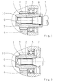
- the drive arrangement comprises a drive pinion 1, which is integrated in a transmission and designed as a hollow shaft, which radially inwardly accommodates an end of a motor shaft 2 of a motor, not shown, facing the transmission.
- the drive pinion 1 engages with its toothing 9 with a spur gear 4 and forms a first gear stage for driving a transmission shaft not shown.
- the drive pinion 1 is mounted on the motor side via a radial ball bearing 3, wherein the radial ball bearing 3 serves as a fixed bearing for the drive pinion 1.
- the drive pinion 1 is supported radially on an axially displaceable hub shaft connection 5 on the motor shaft 2 from.
- the radial ball bearing 3 serves simultaneously in conjunction with the hub shaft connection 5 as a floating bearing for the motor shaft 2, which is mounted on the engine B side with a trained example as a fixed bearing.
- the support of the drive pinion 1 against the motor shaft 2 can be realized via two cylindrical fits 6, 7, which are formed for example as a socket 10, wherein only a socket 10 is shown. In this way, the hub shaft connection 5 can be loaded without lateral forces.
- FIG. 1 the seal is provided on the drive pinion 1, for example via a sealing ring 8.
- FIG. 2 provided the seal directly to the motor shaft 2.
- the proposed drive arrangement can be used in a material handling vehicle. But there are also other applications conceivable.
Landscapes
- Engineering & Computer Science (AREA)
- General Engineering & Computer Science (AREA)
- Mechanical Engineering (AREA)
- Mounting Of Bearings Or Others (AREA)
- Rolling Contact Bearings (AREA)
- Motor Power Transmission Devices (AREA)
- General Details Of Gearings (AREA)
- Arrangement Or Mounting Of Propulsion Units For Vehicles (AREA)
Abstract
Description
- Die vorliegende Erfindung betrifft eine Antriebsanordnung für ein Fahrzeug gemäß der im Oberbegriff des Patentanspruches 1 näher definierten Art.
- Beispielsweise aus den Druckschriften
DE 92 08 118 U1 ,DE 101 32 318 A1 undDE 197 20 783 C2 sind jeweils Radantriebe mit einem Elektromotor und einem Getriebe bekannt. Bei den bekannten Radantrieben ist ein Antriebsritzel direkt auf einer Motorwelle befestigt und bildet mit einem Stirnrad eine erste Getriebestufe zum Antrieb einer Getriebewelle des Getriebes. Hierbei ergibt sich der Nachteil, dass bei der Montage des Motors die Laufverzahnung des Antriebsritzels beziehungsweise des Stirnrades des Getriebes beschädigt werden kann. - Darüber hinaus ist aus der Druckschrift
DE 196 33 316 C2 ein Antrieb für ein Flurfördererfahrzeug bekannt. Der bekannte Antrieb umfasst einen Elektromotor, dessen Motorwelle mit einer Lagerstelle in einem Gehäuse des Getriebes des Antriebes gelagert ist. Nachteilig hierbei ist, dass infolge der kleinen Lagerbasis in dem Getriebegehäuse eine Schiefstellung des Antriebsritzels infolge eines fertigungsbedingten radialen Versatzes des Motors erfolgen kann. - Ferner ist aus der Fahrzeugtechnik bekannt, dass die getriebeseitig gelagerte Motorwelle in einem als Hohlwelle ausgebildeten Antriebsritzel über ein Profil geführt wird. Bei dieser Ausführung ist es nachteilig, dass eine Schiefstellung des Antriebsritzels infolge der kleinen Lagerbasis und dem möglichen Zwang in der Lagerung und der Profilverbindung infolge eines fertigungsbedingten radialen Versatzes des Motors und der Überbestimmung durch die vorgesehenen Lager realisiert wird, welches zu einer verminderten Lebensdauer und zu einer erhöhten Geräuschemission führt.
- Demnach liegt der vorliegenden Erfindung die Aufgabe zu Grunde, eine Antriebsanordnung der eingangs beschriebenen Gattung derart zu gestalten, dass eine Überbestimmung der Lagerung und eine mögliche Schiefstellung des Antriebsritzels bei gleichzeitiger Kostenreduzierung verhindert wird.
- Diese Aufgabe wird erfindungsgemäß durch die Merkmale des Patentanspruches 1 gelöst. Weitere vorteilhafte Ausgestaltungen ergeben sich aus den Unteransprüchen und den Zeichnungen.
- Demnach wird eine Antriebsanordnung für ein Fahrzeug mit einem in ein Getriebe integriertes als Hohlwelle ausgebildetes Antriebsritzel vorgeschlagen, wobei eine zugeordnete Motorwelle drehfest in dem Antriebsritzel bzw. in der Hohlwelle aufgenommen ist und wobei das Antriebsritzel motorseitig über ein als Festlager wirkendes Wälzlager gelagert ist und radial über eine axial verschiebbare Naben-Wellenverbindung auf der Motorwelle abgestützt ist.
- Dadurch, dass bei der erfindungsgemäßen Antriebsanordnung die Lagerung des Antriebsritzels über das als Festlager ausgebildete Wälzlager realisiert wird, kann eine Überbestimmung bei der Lagerung und eine Schiefstellung des Antriebsritzel sicher verhindert werden.
- Vorzugsweise kann als Wälzlager ein Radialrillenkugellager oder dergleichen verwendet werden. Es sind aber auch andere Lageranordnungen einsetzbar, die die vorbeschriebene Wirkung erzielen. Als axial verschiebbare Naben-Wellenverbindung kann gemäß einer nächsten Weiterbildung der Erfindung vorgesehen sein, dass hierfür eine Zahnwellenverbindung, eine Vielkeilverbindung oder dergleichen verwendet wird. Das vorgesehene Radialrillenkugellager dient gleichzeitig in Verbindung mit der Naben-Wellenverbindung als Loslager für die Motorwelle, die beispielsweise an der Motor-B-Seite somit die der Abtriebsseite gegenüberliegenden Seite mit einem als Festlager ausgebildeten Lager, zum Beispiel einem Rillenkugellager, gelagert ist.
- Im Rahmen einer nächsten Ausgestaltung der Erfindung kann vorgesehen sein, dass die Abstützung des als Hohlwelle ausgebildeten Antriebsritzels an der Motorwelle vorzugsweise über zwei zylindrische Passungen oder dergleichen realisiert wird. Beispielsweise können die zylindrischen Passungen mittels Buchsen oder dergleichen realisiert werden.
- Zur axialen Abdichtung können entsprechende Dichtelemente an der Hohlwelle oder auch an der Motorwelle vorgesehen werden.
- Nachfolgend wird die vorliegende Erfindung näher anhand der Zeichnungen erläutert. Es zeigen:
- Figur 1
- eine geschnittene Teilansicht einer ersten möglichen Ausführungs- variante einer erfindungsgemäßen Antriebsanordnung; und
- Figur 2
- eine geschnittene Teilansicht einer zweiten Ausführungsvariante der erfindungsgemäßen Antriebsanordnung.
- In den Figuren sind exemplarisch zwei mögliche Ausführungsvarianten einer erfindungsgemäßen Antriebsanordnung für ein Fahrzeug dargestellt. Die Antriebsanordnung umfasst unabhängig von der jeweiligen Ausführungsvariante ein in einem Getriebe integriertes als Hohlwelle ausgebildetes Antriebsritzel 1, welches radial innen ein dem Getriebe zugewandtes Ende einer Motorwelle 2 eines nicht weiter dargestellten Motors aufnimmt. Das Antriebsritzel 1 steht mit seiner Verzahnung 9 mit einem Stirnrad 4 in Eingriff und bildet eine erste Getriebestufe zum Antrieb einer nicht weiter dargestellten Getriebewelle.
- Erfindungsgemäß ist das Antriebsritzel 1 motorseitig über ein Radialrillenkugellager 3 gelagert, wobei das Radialrillenkugellager 3 als Festlager für das Antriebsritzel 1 dient. Das Antriebsritzel 1 stützt sich radial über eine axial verschiebbare Naben-Wellenverbindung 5 an der Motorwelle 2 ab. Das Radialrillenkugellager 3 dient gleichzeitig in Verbindung mit der Naben-Wellenverbindung 5 als Loslager für die Motorwelle 2, die an der Motor-B-Seite mit einem zum Beispiel als Festlager ausgebildeten Lager gelagert ist.
- Die Abstützung des Antriebsritzels 1 gegen die Motorwelle 2 kann über zwei zylindrische Passungen 6, 7 realisiert werden, welche zum Beispiel als Buchse 10 ausgebildet sind, wobei lediglich eine Buchse 10 dargestellt ist. Auf diese Weise kann die Naben-Wellenverbindung 5 querkraftfrei belastet werden.
- In
Figur 1 ist die Abdichtung an dem Antriebsritzel 1 zum Beispiel über einen Dichtring 8 vorgesehen. Demgegenüber ist inFigur 2 die Abdichtung direkt an der Motorwelle 2 vorgesehen. - Beispielsweise kann die vorgeschlagene Antriebsanordnung bei einem Flurförderfahrzeug verwendet werden. Es sind aber auch andere Einsatzgebiete denkbar.
-
- 1
- Antriebsritzel
- 2
- Motorwelle
- 3
- Radialrillenkugellager
- 4
- Stirnrad
- 5
- Naben-Wellenverbindung
- 6
- Passung
- 7
- Passung
- 8
- Dichtring
- 9
- Verzahnung des Antriebsritzel
- 10
- Buchse
Claims (6)
- Antriebsanordnung eines Fahrzeuges mit einem in ein Getriebe integriertes als Hohlwelle ausgebildetes Antriebsritzel (1), wobei eine zugeordnete Motorwelle (2) drehfest in dem Antriebsritzel (1) aufgenommen ist, dadurch gekennzeichnet, dass das Antriebsritzel (1) motorseitig über ein als Festlager wirkendes Wälzlager gelagert ist und radial über eine axial verschiebbare Naben-Wellenverbindung (5) auf der Motorwelle (2) abgestützt ist.
- Antriebsanordnung nach Anspruch 1, dadurch gekennzeichnet, dass als Wälzlager ein Radialrillenkugellager (3) vorgesehen ist.
- Antriebsanordnung nach Anspruch 1 oder 2, dadurch gekennzeichnet, dass als Naben-Wellenverbindung (3) eine Zahnwellenverbindung und/oder eine Vielkeilverbindung vorgesehen ist.
- Antriebsanordnung nach einem der vorangehenden Ansprüche, dadurch gekennzeichnet, dass die Abstützung des Antriebsritzels (1) an der Motorwelle (2) über zwei zylindrische Passungen (6, 7) vorgesehen sind.
- Antriebsanordnung nach Anspruch 4, dadurch gekennzeichnet, dass die zylindrischen Passungen (6, 7) mittels Buchsen (10) realisiert sind.
- Antriebsanordnung nach einem der vorangehenden Ansprüche, dadurch gekennzeichnet, dass die Abdichtung an dem Antriebsritzel (1) oder an der Motorwelle (2) vorgesehen ist.
Applications Claiming Priority (1)
| Application Number | Priority Date | Filing Date | Title |
|---|---|---|---|
| DE102009027198A DE102009027198A1 (de) | 2009-06-25 | 2009-06-25 | Antriebsanordnung für ein Fahrzeug |
Publications (3)
| Publication Number | Publication Date |
|---|---|
| EP2267337A2 true EP2267337A2 (de) | 2010-12-29 |
| EP2267337A3 EP2267337A3 (de) | 2011-03-02 |
| EP2267337B1 EP2267337B1 (de) | 2011-12-07 |
Family
ID=42937253
Family Applications (1)
| Application Number | Title | Priority Date | Filing Date |
|---|---|---|---|
| EP10157472A Not-in-force EP2267337B1 (de) | 2009-06-25 | 2010-03-24 | Antriebsanordnung für ein Fahrzeug |
Country Status (3)
| Country | Link |
|---|---|
| EP (1) | EP2267337B1 (de) |
| AT (1) | ATE536501T1 (de) |
| DE (1) | DE102009027198A1 (de) |
Cited By (1)
| Publication number | Priority date | Publication date | Assignee | Title |
|---|---|---|---|---|
| US10315515B2 (en) | 2016-08-05 | 2019-06-11 | Honda Motor Co., Ltd. | Power transfer unit pinion shaft and propeller shaft coupling member for a vehicle, and methods of use and manufacture thereof |
Families Citing this family (3)
| Publication number | Priority date | Publication date | Assignee | Title |
|---|---|---|---|---|
| DE102018104685A1 (de) * | 2018-03-01 | 2019-09-05 | Dr. Ing. H.C. F. Porsche Aktiengesellschaft | Antriebsvorrichtung mit einem Elektromotor und einem Getriebe |
| CN108973631A (zh) * | 2018-09-14 | 2018-12-11 | 株洲欧格瑞传动股份有限公司 | 电动汽车及其一体化动力总成 |
| DE102022209749A1 (de) | 2022-09-16 | 2024-03-21 | Zf Friedrichshafen Ag | Antriebseinheit für ein Flurförderzeug und Flurförderzeug |
Citations (4)
| Publication number | Priority date | Publication date | Assignee | Title |
|---|---|---|---|---|
| DE9208118U1 (de) | 1992-06-17 | 1993-07-15 | Kordel Antriebstechnik Gmbh, 4408 Duelmen, De | |
| DE19720783C2 (de) | 1996-10-05 | 2001-10-04 | Kordel Antriebstechnik Gmbh | Einrad-Trieb- und Lenkwerk mit integrierter Bremse für Flurförderfahrzeuge |
| DE19633316C2 (de) | 1996-08-19 | 2002-11-14 | Kordel Antriebstechnik Gmbh | Einrad-Trieb- und Lenkwerk für Flurförderfahrzeuge |
| DE10132318A1 (de) | 2001-07-06 | 2003-01-23 | Kordel Antriebstechnik Gmbh | Einradtriebwerk |
Family Cites Families (5)
| Publication number | Priority date | Publication date | Assignee | Title |
|---|---|---|---|---|
| DE1228945B (de) * | 1962-10-25 | 1966-11-17 | Mannesmann Meer Ag | Hydrostatischer Fahrzeugantrieb |
| US3536230A (en) * | 1968-09-26 | 1970-10-27 | Rockwell Standard Co | Reduction gearing drive control |
| DE3406783C2 (de) * | 1983-02-25 | 1993-11-04 | Linde Ag | Antrieb mit einem hydrostatischen motor |
| DE102005047953A1 (de) * | 2005-10-06 | 2007-04-19 | Zf Friedrichshafen Ag | Antrieb für ein Mobilfahrzeug |
| EP1985487B1 (de) * | 2007-04-24 | 2018-08-08 | Kanzaki Kokyukoki Mfg. Co., Ltd. | Selbstfahrender Rasenmäher |
-
2009
- 2009-06-25 DE DE102009027198A patent/DE102009027198A1/de not_active Withdrawn
-
2010
- 2010-03-24 EP EP10157472A patent/EP2267337B1/de not_active Not-in-force
- 2010-03-24 AT AT10157472T patent/ATE536501T1/de active
Patent Citations (4)
| Publication number | Priority date | Publication date | Assignee | Title |
|---|---|---|---|---|
| DE9208118U1 (de) | 1992-06-17 | 1993-07-15 | Kordel Antriebstechnik Gmbh, 4408 Duelmen, De | |
| DE19633316C2 (de) | 1996-08-19 | 2002-11-14 | Kordel Antriebstechnik Gmbh | Einrad-Trieb- und Lenkwerk für Flurförderfahrzeuge |
| DE19720783C2 (de) | 1996-10-05 | 2001-10-04 | Kordel Antriebstechnik Gmbh | Einrad-Trieb- und Lenkwerk mit integrierter Bremse für Flurförderfahrzeuge |
| DE10132318A1 (de) | 2001-07-06 | 2003-01-23 | Kordel Antriebstechnik Gmbh | Einradtriebwerk |
Cited By (1)
| Publication number | Priority date | Publication date | Assignee | Title |
|---|---|---|---|---|
| US10315515B2 (en) | 2016-08-05 | 2019-06-11 | Honda Motor Co., Ltd. | Power transfer unit pinion shaft and propeller shaft coupling member for a vehicle, and methods of use and manufacture thereof |
Also Published As
| Publication number | Publication date |
|---|---|
| EP2267337B1 (de) | 2011-12-07 |
| DE102009027198A1 (de) | 2010-12-30 |
| ATE536501T1 (de) | 2011-12-15 |
| EP2267337A3 (de) | 2011-03-02 |
Similar Documents
| Publication | Publication Date | Title |
|---|---|---|
| EP2737612B1 (de) | Radnahe antriebseinheit für ein kraftfahrzeug | |
| EP1961101B1 (de) | Lagersystem für einen Elektromotor und Elektromotor | |
| EP2267337B1 (de) | Antriebsanordnung für ein Fahrzeug | |
| EP1917157B1 (de) | Getriebestufe | |
| DE102018205473A1 (de) | Lagerung für ein Hybridmodul | |
| DE102010001637A1 (de) | Antriebsanordnung für ein Flurförderfahrzeug | |
| DE102009047730A1 (de) | Lenkbare Antriebsanordnung für ein Flurförderfahrzeug | |
| DE102009050121B4 (de) | Untersetzungsgetriebe mit Schnecke und Schneckenrad | |
| DE102008002769A1 (de) | Schraubradgetriebe und damit ausgestattete elektrische Hilfskraftlenkung | |
| DE102012007329A1 (de) | Welle-Nabe-Verbindung | |
| DE102013209202A1 (de) | Antriebseinrichtung, insbesondere Stelleinrichtung in einem Fahrzeug | |
| EP1377489B1 (de) | Fahrzeugantrieb mit bogenzahnkupplung | |
| DE102009026706A1 (de) | Lageranordnung für eine Welle | |
| EP2056430B1 (de) | Motor-Getriebemodul | |
| DE102019209060A1 (de) | Antriebseinheit für ein Flurförderzeug, Antriebsachse für ein Flurförderzeug, Flurförderzeug und Verfahren zur Montage einer Antriebseinheit für ein Flurförderfahrzeug | |
| DE102005035292A1 (de) | Antriebseinheit | |
| DE102010029611A1 (de) | Lenkbare Antriebsanordnung für ein deichselgeführtes Flurförderzeug | |
| DE102007017699A1 (de) | Lenkbarer Antrieb für ein Flurförderfahrzeug | |
| WO2020109144A1 (de) | Antriebseinrichtung für ein kraftfahrzeug mit einer antriebseinheit | |
| DE102009002935A1 (de) | Lenkbare Fahrzeugachse | |
| DE102005018498B4 (de) | Lagerung eines Aggregats einer Brennkraftmaschine | |
| DE102012206437A1 (de) | Modifizierter Lagerinnenring zur Zentrierung eines Planetenträgers bei radial innerhalb vom Planetenträger angebrachter Positionierung des Lagerrings | |
| DE102010029549A1 (de) | Lenkbare Antriebsanordnung für ein deichselgeführtes Flurförderzeug | |
| DE102020203820A1 (de) | Antriebseinheit für ein Flurförderzeug, Antriebsachse für ein Flurförderzeug und Flurförderzeug | |
| DE102009045083A1 (de) | Lageranordnung |
Legal Events
| Date | Code | Title | Description |
|---|---|---|---|
| PUAI | Public reference made under article 153(3) epc to a published international application that has entered the european phase |
Free format text: ORIGINAL CODE: 0009012 |
|
| AK | Designated contracting states |
Kind code of ref document: A2 Designated state(s): AT BE BG CH CY CZ DE DK EE ES FI FR GB GR HR HU IE IS IT LI LT LU LV MC MK MT NL NO PL PT RO SE SI SK SM TR |
|
| AX | Request for extension of the european patent |
Extension state: AL BA ME RS |
|
| PUAL | Search report despatched |
Free format text: ORIGINAL CODE: 0009013 |
|
| AK | Designated contracting states |
Kind code of ref document: A3 Designated state(s): AT BE BG CH CY CZ DE DK EE ES FI FR GB GR HR HU IE IS IT LI LT LU LV MC MK MT NL NO PL PT RO SE SI SK SM TR |
|
| AX | Request for extension of the european patent |
Extension state: AL BA ME RS |
|
| 17P | Request for examination filed |
Effective date: 20110211 |
|
| GRAP | Despatch of communication of intention to grant a patent |
Free format text: ORIGINAL CODE: EPIDOSNIGR1 |
|
| RIC1 | Information provided on ipc code assigned before grant |
Ipc: F16H 57/02 20060101AFI20110624BHEP |
|
| GRAS | Grant fee paid |
Free format text: ORIGINAL CODE: EPIDOSNIGR3 |
|
| GRAA | (expected) grant |
Free format text: ORIGINAL CODE: 0009210 |
|
| AK | Designated contracting states |
Kind code of ref document: B1 Designated state(s): AT BE BG CH CY CZ DE DK EE ES FI FR GB GR HR HU IE IS IT LI LT LU LV MC MK MT NL NO PL PT RO SE SI SK SM TR |
|
| REG | Reference to a national code |
Ref country code: GB Ref legal event code: FG4D Free format text: NOT ENGLISH |
|
| REG | Reference to a national code |
Ref country code: CH Ref legal event code: EP |
|
| REG | Reference to a national code |
Ref country code: IE Ref legal event code: FG4D Free format text: LANGUAGE OF EP DOCUMENT: GERMAN |
|
| REG | Reference to a national code |
Ref country code: DE Ref legal event code: R096 Ref document number: 502010000258 Country of ref document: DE Effective date: 20120202 |
|
| REG | Reference to a national code |
Ref country code: NL Ref legal event code: VDEP Effective date: 20111207 |
|
| PG25 | Lapsed in a contracting state [announced via postgrant information from national office to epo] |
Ref country code: LT Free format text: LAPSE BECAUSE OF FAILURE TO SUBMIT A TRANSLATION OF THE DESCRIPTION OR TO PAY THE FEE WITHIN THE PRESCRIBED TIME-LIMIT Effective date: 20111207 Ref country code: NO Free format text: LAPSE BECAUSE OF FAILURE TO SUBMIT A TRANSLATION OF THE DESCRIPTION OR TO PAY THE FEE WITHIN THE PRESCRIBED TIME-LIMIT Effective date: 20120307 |
|
| LTIE | Lt: invalidation of european patent or patent extension |
Effective date: 20111207 |
|
| PG25 | Lapsed in a contracting state [announced via postgrant information from national office to epo] |
Ref country code: HR Free format text: LAPSE BECAUSE OF FAILURE TO SUBMIT A TRANSLATION OF THE DESCRIPTION OR TO PAY THE FEE WITHIN THE PRESCRIBED TIME-LIMIT Effective date: 20111207 Ref country code: LV Free format text: LAPSE BECAUSE OF FAILURE TO SUBMIT A TRANSLATION OF THE DESCRIPTION OR TO PAY THE FEE WITHIN THE PRESCRIBED TIME-LIMIT Effective date: 20111207 Ref country code: GR Free format text: LAPSE BECAUSE OF FAILURE TO SUBMIT A TRANSLATION OF THE DESCRIPTION OR TO PAY THE FEE WITHIN THE PRESCRIBED TIME-LIMIT Effective date: 20120308 Ref country code: SE Free format text: LAPSE BECAUSE OF FAILURE TO SUBMIT A TRANSLATION OF THE DESCRIPTION OR TO PAY THE FEE WITHIN THE PRESCRIBED TIME-LIMIT Effective date: 20111207 Ref country code: NL Free format text: LAPSE BECAUSE OF FAILURE TO SUBMIT A TRANSLATION OF THE DESCRIPTION OR TO PAY THE FEE WITHIN THE PRESCRIBED TIME-LIMIT Effective date: 20111207 Ref country code: SI Free format text: LAPSE BECAUSE OF FAILURE TO SUBMIT A TRANSLATION OF THE DESCRIPTION OR TO PAY THE FEE WITHIN THE PRESCRIBED TIME-LIMIT Effective date: 20111207 |
|
| PG25 | Lapsed in a contracting state [announced via postgrant information from national office to epo] |
Ref country code: CY Free format text: LAPSE BECAUSE OF FAILURE TO SUBMIT A TRANSLATION OF THE DESCRIPTION OR TO PAY THE FEE WITHIN THE PRESCRIBED TIME-LIMIT Effective date: 20111207 |
|
| REG | Reference to a national code |
Ref country code: IE Ref legal event code: FD4D |
|
| PG25 | Lapsed in a contracting state [announced via postgrant information from national office to epo] |
Ref country code: CZ Free format text: LAPSE BECAUSE OF FAILURE TO SUBMIT A TRANSLATION OF THE DESCRIPTION OR TO PAY THE FEE WITHIN THE PRESCRIBED TIME-LIMIT Effective date: 20111207 Ref country code: BG Free format text: LAPSE BECAUSE OF FAILURE TO SUBMIT A TRANSLATION OF THE DESCRIPTION OR TO PAY THE FEE WITHIN THE PRESCRIBED TIME-LIMIT Effective date: 20120307 Ref country code: IS Free format text: LAPSE BECAUSE OF FAILURE TO SUBMIT A TRANSLATION OF THE DESCRIPTION OR TO PAY THE FEE WITHIN THE PRESCRIBED TIME-LIMIT Effective date: 20120407 Ref country code: EE Free format text: LAPSE BECAUSE OF FAILURE TO SUBMIT A TRANSLATION OF THE DESCRIPTION OR TO PAY THE FEE WITHIN THE PRESCRIBED TIME-LIMIT Effective date: 20111207 Ref country code: SK Free format text: LAPSE BECAUSE OF FAILURE TO SUBMIT A TRANSLATION OF THE DESCRIPTION OR TO PAY THE FEE WITHIN THE PRESCRIBED TIME-LIMIT Effective date: 20111207 Ref country code: IE Free format text: LAPSE BECAUSE OF FAILURE TO SUBMIT A TRANSLATION OF THE DESCRIPTION OR TO PAY THE FEE WITHIN THE PRESCRIBED TIME-LIMIT Effective date: 20111207 |
|
| PG25 | Lapsed in a contracting state [announced via postgrant information from national office to epo] |
Ref country code: RO Free format text: LAPSE BECAUSE OF FAILURE TO SUBMIT A TRANSLATION OF THE DESCRIPTION OR TO PAY THE FEE WITHIN THE PRESCRIBED TIME-LIMIT Effective date: 20111207 Ref country code: PL Free format text: LAPSE BECAUSE OF FAILURE TO SUBMIT A TRANSLATION OF THE DESCRIPTION OR TO PAY THE FEE WITHIN THE PRESCRIBED TIME-LIMIT Effective date: 20111207 Ref country code: PT Free format text: LAPSE BECAUSE OF FAILURE TO SUBMIT A TRANSLATION OF THE DESCRIPTION OR TO PAY THE FEE WITHIN THE PRESCRIBED TIME-LIMIT Effective date: 20120409 |
|
| BERE | Be: lapsed |
Owner name: ZF FRIEDRICHSHAFEN A.G. Effective date: 20120331 |
|
| PLBE | No opposition filed within time limit |
Free format text: ORIGINAL CODE: 0009261 |
|
| STAA | Information on the status of an ep patent application or granted ep patent |
Free format text: STATUS: NO OPPOSITION FILED WITHIN TIME LIMIT |
|
| PG25 | Lapsed in a contracting state [announced via postgrant information from national office to epo] |
Ref country code: DK Free format text: LAPSE BECAUSE OF FAILURE TO SUBMIT A TRANSLATION OF THE DESCRIPTION OR TO PAY THE FEE WITHIN THE PRESCRIBED TIME-LIMIT Effective date: 20111207 Ref country code: MC Free format text: LAPSE BECAUSE OF NON-PAYMENT OF DUE FEES Effective date: 20120331 |
|
| 26N | No opposition filed |
Effective date: 20120910 |
|
| PG25 | Lapsed in a contracting state [announced via postgrant information from national office to epo] |
Ref country code: IT Free format text: LAPSE BECAUSE OF FAILURE TO SUBMIT A TRANSLATION OF THE DESCRIPTION OR TO PAY THE FEE WITHIN THE PRESCRIBED TIME-LIMIT Effective date: 20111207 |
|
| REG | Reference to a national code |
Ref country code: FR Ref legal event code: ST Effective date: 20121130 |
|
| REG | Reference to a national code |
Ref country code: DE Ref legal event code: R097 Ref document number: 502010000258 Country of ref document: DE Effective date: 20120910 |
|
| PG25 | Lapsed in a contracting state [announced via postgrant information from national office to epo] |
Ref country code: FR Free format text: LAPSE BECAUSE OF NON-PAYMENT OF DUE FEES Effective date: 20120402 Ref country code: BE Free format text: LAPSE BECAUSE OF NON-PAYMENT OF DUE FEES Effective date: 20120331 |
|
| PG25 | Lapsed in a contracting state [announced via postgrant information from national office to epo] |
Ref country code: MK Free format text: LAPSE BECAUSE OF FAILURE TO SUBMIT A TRANSLATION OF THE DESCRIPTION OR TO PAY THE FEE WITHIN THE PRESCRIBED TIME-LIMIT Effective date: 20111207 |
|
| PG25 | Lapsed in a contracting state [announced via postgrant information from national office to epo] |
Ref country code: ES Free format text: LAPSE BECAUSE OF FAILURE TO SUBMIT A TRANSLATION OF THE DESCRIPTION OR TO PAY THE FEE WITHIN THE PRESCRIBED TIME-LIMIT Effective date: 20120318 |
|
| PG25 | Lapsed in a contracting state [announced via postgrant information from national office to epo] |
Ref country code: FI Free format text: LAPSE BECAUSE OF FAILURE TO SUBMIT A TRANSLATION OF THE DESCRIPTION OR TO PAY THE FEE WITHIN THE PRESCRIBED TIME-LIMIT Effective date: 20111207 |
|
| PG25 | Lapsed in a contracting state [announced via postgrant information from national office to epo] |
Ref country code: MT Free format text: LAPSE BECAUSE OF FAILURE TO SUBMIT A TRANSLATION OF THE DESCRIPTION OR TO PAY THE FEE WITHIN THE PRESCRIBED TIME-LIMIT Effective date: 20111207 |
|
| PG25 | Lapsed in a contracting state [announced via postgrant information from national office to epo] |
Ref country code: TR Free format text: LAPSE BECAUSE OF FAILURE TO SUBMIT A TRANSLATION OF THE DESCRIPTION OR TO PAY THE FEE WITHIN THE PRESCRIBED TIME-LIMIT Effective date: 20111207 |
|
| PG25 | Lapsed in a contracting state [announced via postgrant information from national office to epo] |
Ref country code: LU Free format text: LAPSE BECAUSE OF NON-PAYMENT OF DUE FEES Effective date: 20120324 Ref country code: SM Free format text: LAPSE BECAUSE OF FAILURE TO SUBMIT A TRANSLATION OF THE DESCRIPTION OR TO PAY THE FEE WITHIN THE PRESCRIBED TIME-LIMIT Effective date: 20111207 |
|
| PG25 | Lapsed in a contracting state [announced via postgrant information from national office to epo] |
Ref country code: HU Free format text: LAPSE BECAUSE OF FAILURE TO SUBMIT A TRANSLATION OF THE DESCRIPTION OR TO PAY THE FEE WITHIN THE PRESCRIBED TIME-LIMIT Effective date: 20100324 |
|
| PGFP | Annual fee paid to national office [announced via postgrant information from national office to epo] |
Ref country code: DE Payment date: 20140417 Year of fee payment: 5 |
|
| REG | Reference to a national code |
Ref country code: CH Ref legal event code: PL |
|
| GBPC | Gb: european patent ceased through non-payment of renewal fee |
Effective date: 20140324 |
|
| PG25 | Lapsed in a contracting state [announced via postgrant information from national office to epo] |
Ref country code: CH Free format text: LAPSE BECAUSE OF NON-PAYMENT OF DUE FEES Effective date: 20140331 Ref country code: LI Free format text: LAPSE BECAUSE OF NON-PAYMENT OF DUE FEES Effective date: 20140331 Ref country code: GB Free format text: LAPSE BECAUSE OF NON-PAYMENT OF DUE FEES Effective date: 20140324 |
|
| REG | Reference to a national code |
Ref country code: DE Ref legal event code: R119 Ref document number: 502010000258 Country of ref document: DE |
|
| PG25 | Lapsed in a contracting state [announced via postgrant information from national office to epo] |
Ref country code: DE Free format text: LAPSE BECAUSE OF NON-PAYMENT OF DUE FEES Effective date: 20151001 |
|
| REG | Reference to a national code |
Ref country code: AT Ref legal event code: MM01 Ref document number: 536501 Country of ref document: AT Kind code of ref document: T Effective date: 20150324 |
|
| PG25 | Lapsed in a contracting state [announced via postgrant information from national office to epo] |
Ref country code: AT Free format text: LAPSE BECAUSE OF NON-PAYMENT OF DUE FEES Effective date: 20150324 |