EP2265194B1 - Chirurgisches führungsinstrument für hüftgelenkstotalersatz - Google Patents
Chirurgisches führungsinstrument für hüftgelenkstotalersatz Download PDFInfo
- Publication number
- EP2265194B1 EP2265194B1 EP09718041.8A EP09718041A EP2265194B1 EP 2265194 B1 EP2265194 B1 EP 2265194B1 EP 09718041 A EP09718041 A EP 09718041A EP 2265194 B1 EP2265194 B1 EP 2265194B1
- Authority
- EP
- European Patent Office
- Prior art keywords
- model
- femur
- tool
- mating
- region
- Prior art date
- Legal status (The legal status is an assumption and is not a legal conclusion. Google has not performed a legal analysis and makes no representation as to the accuracy of the status listed.)
- Active
Links
Images











Classifications
-
- A—HUMAN NECESSITIES
- A61—MEDICAL OR VETERINARY SCIENCE; HYGIENE
- A61B—DIAGNOSIS; SURGERY; IDENTIFICATION
- A61B17/00—Surgical instruments, devices or methods
- A61B17/16—Instruments for performing osteoclasis; Drills or chisels for bones; Trepans
- A61B17/17—Guides or aligning means for drills, mills, pins or wires
- A61B17/1739—Guides or aligning means for drills, mills, pins or wires specially adapted for particular parts of the body
- A61B17/1742—Guides or aligning means for drills, mills, pins or wires specially adapted for particular parts of the body for the hip
- A61B17/175—Guides or aligning means for drills, mills, pins or wires specially adapted for particular parts of the body for the hip for preparing the femur for hip prosthesis insertion
-
- A—HUMAN NECESSITIES
- A61—MEDICAL OR VETERINARY SCIENCE; HYGIENE
- A61B—DIAGNOSIS; SURGERY; IDENTIFICATION
- A61B17/00—Surgical instruments, devices or methods
- A61B17/14—Surgical saws
- A61B17/15—Guides therefor
-
- A—HUMAN NECESSITIES
- A61—MEDICAL OR VETERINARY SCIENCE; HYGIENE
- A61B—DIAGNOSIS; SURGERY; IDENTIFICATION
- A61B34/00—Computer-aided surgery; Manipulators or robots specially adapted for use in surgery
- A61B34/10—Computer-aided planning, simulation or modelling of surgical operations
-
- A—HUMAN NECESSITIES
- A61—MEDICAL OR VETERINARY SCIENCE; HYGIENE
- A61F—FILTERS IMPLANTABLE INTO BLOOD VESSELS; PROSTHESES; DEVICES PROVIDING PATENCY TO, OR PREVENTING COLLAPSING OF, TUBULAR STRUCTURES OF THE BODY, e.g. STENTS; ORTHOPAEDIC, NURSING OR CONTRACEPTIVE DEVICES; FOMENTATION; TREATMENT OR PROTECTION OF EYES OR EARS; BANDAGES, DRESSINGS OR ABSORBENT PADS; FIRST-AID KITS
- A61F2/00—Filters implantable into blood vessels; Prostheses, i.e. artificial substitutes or replacements for parts of the body; Appliances for connecting them with the body; Devices providing patency to, or preventing collapsing of, tubular structures of the body, e.g. stents
- A61F2/02—Prostheses implantable into the body
- A61F2/30—Joints
- A61F2/32—Joints for the hip
- A61F2/36—Femoral heads ; Femoral endoprostheses
- A61F2/3609—Femoral heads or necks; Connections of endoprosthetic heads or necks to endoprosthetic femoral shafts
-
- G—PHYSICS
- G05—CONTROLLING; REGULATING
- G05B—CONTROL OR REGULATING SYSTEMS IN GENERAL; FUNCTIONAL ELEMENTS OF SUCH SYSTEMS; MONITORING OR TESTING ARRANGEMENTS FOR SUCH SYSTEMS OR ELEMENTS
- G05B19/00—Program-control systems
- G05B19/02—Program-control systems electric
- G05B19/418—Total factory control, i.e. centrally controlling a plurality of machines, e.g. direct or distributed numerical control [DNC], flexible manufacturing systems [FMS], integrated manufacturing systems [IMS] or computer integrated manufacturing [CIM]
- G05B19/41885—Total factory control, i.e. centrally controlling a plurality of machines, e.g. direct or distributed numerical control [DNC], flexible manufacturing systems [FMS], integrated manufacturing systems [IMS] or computer integrated manufacturing [CIM] characterised by modeling, simulation of the manufacturing system
-
- A—HUMAN NECESSITIES
- A61—MEDICAL OR VETERINARY SCIENCE; HYGIENE
- A61B—DIAGNOSIS; SURGERY; IDENTIFICATION
- A61B17/00—Surgical instruments, devices or methods
- A61B17/56—Surgical instruments or methods for treatment of bones or joints; Devices specially adapted therefor
- A61B2017/568—Surgical instruments or methods for treatment of bones or joints; Devices specially adapted therefor produced with shape and dimensions specific for an individual patient
-
- A—HUMAN NECESSITIES
- A61—MEDICAL OR VETERINARY SCIENCE; HYGIENE
- A61B—DIAGNOSIS; SURGERY; IDENTIFICATION
- A61B34/00—Computer-aided surgery; Manipulators or robots specially adapted for use in surgery
- A61B34/10—Computer-aided planning, simulation or modelling of surgical operations
- A61B2034/101—Computer-aided simulation of surgical operations
- A61B2034/102—Modelling of surgical devices, implants or prosthesis
-
- A—HUMAN NECESSITIES
- A61—MEDICAL OR VETERINARY SCIENCE; HYGIENE
- A61B—DIAGNOSIS; SURGERY; IDENTIFICATION
- A61B34/00—Computer-aided surgery; Manipulators or robots specially adapted for use in surgery
- A61B34/10—Computer-aided planning, simulation or modelling of surgical operations
- A61B2034/101—Computer-aided simulation of surgical operations
- A61B2034/105—Modelling of the patient, e.g. for ligaments or bones
-
- A—HUMAN NECESSITIES
- A61—MEDICAL OR VETERINARY SCIENCE; HYGIENE
- A61B—DIAGNOSIS; SURGERY; IDENTIFICATION
- A61B34/00—Computer-aided surgery; Manipulators or robots specially adapted for use in surgery
- A61B34/10—Computer-aided planning, simulation or modelling of surgical operations
- A61B2034/107—Visualisation of planned trajectories or target regions
-
- A—HUMAN NECESSITIES
- A61—MEDICAL OR VETERINARY SCIENCE; HYGIENE
- A61B—DIAGNOSIS; SURGERY; IDENTIFICATION
- A61B34/00—Computer-aided surgery; Manipulators or robots specially adapted for use in surgery
- A61B34/10—Computer-aided planning, simulation or modelling of surgical operations
- A61B2034/108—Computer aided selection or customisation of medical implants or cutting guides
-
- A—HUMAN NECESSITIES
- A61—MEDICAL OR VETERINARY SCIENCE; HYGIENE
- A61F—FILTERS IMPLANTABLE INTO BLOOD VESSELS; PROSTHESES; DEVICES PROVIDING PATENCY TO, OR PREVENTING COLLAPSING OF, TUBULAR STRUCTURES OF THE BODY, e.g. STENTS; ORTHOPAEDIC, NURSING OR CONTRACEPTIVE DEVICES; FOMENTATION; TREATMENT OR PROTECTION OF EYES OR EARS; BANDAGES, DRESSINGS OR ABSORBENT PADS; FIRST-AID KITS
- A61F2/00—Filters implantable into blood vessels; Prostheses, i.e. artificial substitutes or replacements for parts of the body; Appliances for connecting them with the body; Devices providing patency to, or preventing collapsing of, tubular structures of the body, e.g. stents
- A61F2/02—Prostheses implantable into the body
- A61F2/30—Joints
- A61F2/32—Joints for the hip
- A61F2/36—Femoral heads ; Femoral endoprostheses
- A61F2/3601—Femoral heads ; Femoral endoprostheses for replacing only the epiphyseal or metaphyseal parts of the femur, e.g. endoprosthetic femoral heads or necks directly fixed to the natural femur by internal fixation devices
- A61F2/3603—Femoral heads ; Femoral endoprostheses for replacing only the epiphyseal or metaphyseal parts of the femur, e.g. endoprosthetic femoral heads or necks directly fixed to the natural femur by internal fixation devices implanted without ablation of the whole natural femoral head
-
- A—HUMAN NECESSITIES
- A61—MEDICAL OR VETERINARY SCIENCE; HYGIENE
- A61F—FILTERS IMPLANTABLE INTO BLOOD VESSELS; PROSTHESES; DEVICES PROVIDING PATENCY TO, OR PREVENTING COLLAPSING OF, TUBULAR STRUCTURES OF THE BODY, e.g. STENTS; ORTHOPAEDIC, NURSING OR CONTRACEPTIVE DEVICES; FOMENTATION; TREATMENT OR PROTECTION OF EYES OR EARS; BANDAGES, DRESSINGS OR ABSORBENT PADS; FIRST-AID KITS
- A61F2/00—Filters implantable into blood vessels; Prostheses, i.e. artificial substitutes or replacements for parts of the body; Appliances for connecting them with the body; Devices providing patency to, or preventing collapsing of, tubular structures of the body, e.g. stents
- A61F2/02—Prostheses implantable into the body
- A61F2/30—Joints
- A61F2/30767—Special external or bone-contacting surface, e.g. coating for improving bone ingrowth
- A61F2/30771—Special external or bone-contacting surface, e.g. coating for improving bone ingrowth applied in original prostheses, e.g. holes or grooves
- A61F2002/30878—Special external or bone-contacting surface, e.g. coating for improving bone ingrowth applied in original prostheses, e.g. holes or grooves with non-sharp protrusions, for instance contacting the bone for anchoring, e.g. keels, pegs, pins, posts, shanks, stems, struts
-
- A—HUMAN NECESSITIES
- A61—MEDICAL OR VETERINARY SCIENCE; HYGIENE
- A61F—FILTERS IMPLANTABLE INTO BLOOD VESSELS; PROSTHESES; DEVICES PROVIDING PATENCY TO, OR PREVENTING COLLAPSING OF, TUBULAR STRUCTURES OF THE BODY, e.g. STENTS; ORTHOPAEDIC, NURSING OR CONTRACEPTIVE DEVICES; FOMENTATION; TREATMENT OR PROTECTION OF EYES OR EARS; BANDAGES, DRESSINGS OR ABSORBENT PADS; FIRST-AID KITS
- A61F2/00—Filters implantable into blood vessels; Prostheses, i.e. artificial substitutes or replacements for parts of the body; Appliances for connecting them with the body; Devices providing patency to, or preventing collapsing of, tubular structures of the body, e.g. stents
- A61F2/50—Prostheses not implantable in the body
- A61F2/5044—Designing or manufacturing processes
- A61F2/5046—Designing or manufacturing processes for designing or making customized prostheses, e.g. using templates, finite-element analysis or CAD-CAM techniques
- A61F2002/505—Designing or manufacturing processes for designing or making customized prostheses, e.g. using templates, finite-element analysis or CAD-CAM techniques using CAD-CAM techniques or NC-techniques
-
- B—PERFORMING OPERATIONS; TRANSPORTING
- B33—ADDITIVE MANUFACTURING TECHNOLOGY
- B33Y—ADDITIVE MANUFACTURING, i.e. MANUFACTURING OF THREE-DIMENSIONAL [3D] OBJECTS BY ADDITIVE DEPOSITION, ADDITIVE AGGLOMERATION OR ADDITIVE LAYERING, e.g. BY 3D PRINTING, STEREOLITHOGRAPHY OR SELECTIVE LASER SINTERING
- B33Y80/00—Products made by additive manufacturing
-
- Y—GENERAL TAGGING OF NEW TECHNOLOGICAL DEVELOPMENTS; GENERAL TAGGING OF CROSS-SECTIONAL TECHNOLOGIES SPANNING OVER SEVERAL SECTIONS OF THE IPC; TECHNICAL SUBJECTS COVERED BY FORMER USPC CROSS-REFERENCE ART COLLECTIONS [XRACs] AND DIGESTS
- Y02—TECHNOLOGIES OR APPLICATIONS FOR MITIGATION OR ADAPTATION AGAINST CLIMATE CHANGE
- Y02P—CLIMATE CHANGE MITIGATION TECHNOLOGIES IN THE PRODUCTION OR PROCESSING OF GOODS
- Y02P90/00—Enabling technologies with a potential contribution to greenhouse gas [GHG] emissions mitigation
- Y02P90/02—Total factory control, e.g. smart factories, flexible manufacturing systems [FMS] or integrated manufacturing systems [IMS]
Definitions
- the present invention relates to a method of manufacturing a surgical guide tool for use in total hip replacement surgery.
- Arthroplasty is an orthopedic surgical procedure in which a dysfunctional or arthritic joint surface is replaced, remodeled or redesigned to alleviate pain, restore range of motion or to fix physical joint damage caused by a fracture.
- Total Hip Replacement (“THR”) surgery also known as hip arthroplasty, is a surgical procedure wherein the proximal femur, with its femoral head and neck, is removed and a prosthetic device (or stem) having a prosthetic femoral head is implanted into the femur.
- the acetabulum, or hip socket is also replaced or modified to accept a cup.
- the cup is configured to receive the prosthetic head.
- the prosthetic device (or stem) is typically made of titanium or a titanium alloy.
- the head may be made of a biocompatible plastic, ceramic or other suitable material.
- the cup may be made of a biocompatible plastic or other suitable material.
- the prosthetic device and the cup are typically anchored to the bone with bone cement.
- the surgeon will take a number of measurements by hand or x-ray scan related to proper selection of the prosthetic device, limb length, and hip rotation.
- the femur is pushed out of socket to expose the joint cavity and the deteriorated or damaged femoral head is removed.
- the femur is then prepared to receive the stem by cleaning and enlarging the hollow center portion of the bone, thereby creating a cavity that matches the shape of the implant stem.
- the top end of the femur is planed and smoothed so the stem can be inserted flush with the bone surface. If the head is a separate piece, the proper size is selected and attached. Finally, the head is seated within the cup so the joint is properly aligned and the incision is closed.
- Hand measuring techniques and x-ray scans are inaccurate and increase the error rate or potential for error in a THR, and may lead to an improperly positioned prosthetic device. Improper positioning of the prosthetic device can result in a change of leg length, dislocation of the hip or perforation of the femur.
- US200510148843-A discloses a method for designing a surgical guide for a joint replacement prosthesis which includes generating control data from a surgical guide image so that the control data may be used to control operation of a machine to fabricate a surgical guide.
- WO20071097853 discloses a method in which a near-shape arthroplasty jig blank has at least one feature specific to a target site to be matched by an arthroplasty jig.
- the present disclosure describes a customized surgical guide tool 5 for use in total hip replacement surgery ("THR").
- the customized surgical guide tool 5 may be preoperatively planned via three-dimensional ("3D") computer modeling procedures such that, when the tool 5 is matingly engaged with the proximal femur 40 of the patient, a resection guided by the tool 5 will result in a desired resection that will allow a femoral prosthetic implant or component 800 to be implanted in the femur 40 as planned during the preoperative planning.
- 3D three-dimensional
- the tool 5 may include a single-piece construction, a fastener receiving feature 1710, a customized saw guide 1725, and a customized indexing or mating region 20 having customized indexing or mating surfaces 708a, 710a.
- the fastener receiving feature 1710 may be used to receive an anchor that may secure the tool 5 in mating engagement with the proximal femur 40.
- the mating region 20 and its mating surfaces 708a, 710a may be configured such that, when the mating region 20 matingly receives therein a region of the proximal femur 40 having predetermined bone surfaces 708, 710, the mating surfaces 708a, 710a of the mating region 20 of the tool 5 will matingly contact the predetermined bone surfaces 708, 710 on the proximal femur 40.
- the mating region 20 may also include non-contacting surfaces 718a, 720a that correspond to surfaces of proximal femur 40 that are within the region of the femur engaged by the tool mating region 20 and that have surface topography of such variation that it is difficult to accurately scan or computer model or too small to manufacture into the tool mating region.
- These non-contacting surfaces 718a, 720a of the tool mating region 20 may be the result of an overestimation process during image segmentation and will be spaced apart in a non-contacting fashion from the adjacent femur surfaces when the tool mating region 20 matingly receives the femur 40.
- the saw guide 1725 may be a slot, planar surface, or other feature capable of guiding a saw blade during a sawing procedure.
- the saw guide 1725 may be positioned and oriented relative to the customized mating or indexing region 20 such that, when the mating surfaces 708a, 710a of the mating region 20 matingly contact the bone surfaces 708, 710 when the tool mating region 20 matingly receives therein the region of the femur 40 having the bone surfaces 708, 710, the saw guide 1725 may be oriented over the femur neck 35 such that the saw guide 1725 corresponds with a desired resection plane 805 through the femoral neck 35 that was identified during the preoperative planning.
- the resection plane 805 may correspond with a spacer region 803 of the femoral prosthetic implant or component 800 that limits the extent to which the femoral component may be inserted into the resected proximal femur during implantation.
- the femoral component 800 which may be selected based on the information obtained during the preoperative planning, may then be inserted into the resected proximal femur 40.
- the tool 5 may have a single-piece construction, which may increase the accuracy associated with the resectioning process by minimizing tolerance errors normally associated with multi-piece, multi-joint, conventional guide tools.
- the tool 5 may have a multi-piece construction.
- the saw slot 1725 may be in the form of a separate guide that is mounted on the rest of the tool 5 in an indexed manner, the rest of the tool 5 having the customized mating region having the customized mating surfaces.
- the guide tool 5 aids the surgeon in accurately implanting the femoral component 800 during a THR according to an alignment and position determined during preoperative planning.
- the tool 5 once matingly engaged with the proximal femur, may guide the resection of the proximal femur according to a resection plane identified during the preoperative planning.
- Accurate implant alignment and position is important because an improperly positioned and aligned femoral component 800 may result in a change of leg length, dislocation of the hip or perforation of the femur.
- the tool 5 is configured to generally automatically provide an appropriate resection through the femur neck for a proper alignment of the femoral component upon causing the indexing region 20 to matingly receive the region of the femur having the bone surfaces 708, 710, the time and effort required by the surgeon to properly prepare the femur for the implantation of the femoral component 800 is substantially minimized.
- use of the tool 5 may reduce the overall time spent in surgery. The reduction in the time spent in surgery may reduce the patient's chances of infection.
- a three dimensional (“3D”) model of the patient's proximal femur 40 is computer generated from two dimensional ("2D") medical imaging slices 500 (e.g., CT slices, MRI slices, etc.) taken of the patient's proximal femur 40.
- a sphere 3D computer model 701 and a rod 3D computer model 702 may be respectively aligned with the femoral head 30 and medullary canal 170 or the central axis 100 of the femur shaft of the femur 3D computer model 1040 to approximate the positioning of the femoral component 800 relative to the center of the hip joint 703.
- a 3D model of the femoral component 800 may be selected from a database of 3D models of candidate femoral component 800.
- the selected 3D model of the femoral component may be aligned with the 3D model of the femur 40 and the sphere and rod models 701, 702 such that the component head is generally centered with the center of the sphere model and the component shaft is generally coaxial with the rod model.
- a 3D model of a blank of the tool 5 may be positioned on the femur model, which is still aligned with the sphere, rod and femoral component models 701, 702, 800.
- the resection plane may be determined from the location of a distal end 803 of a spacer region 801 of the femoral component 800 and used to define a saw slot 1725 in the 3D model of the blank of the tool 5.
- the 3D model of the femur is analyzed to determine shape and location of the mating or indexing femur surfaces 708, 710.
- the shape and location of the surfaces 708, 710 may be used to define corresponding mating surfaces 708a, 710a in the mating region 20 of the 3D model of the blank of the tool 5.
- the indexing surfaces 708a, 710a of the mating region 20, the saw slot 1725, and the orientation relationships between the surfaces 708a, 710a and the saw slot 1725 may be imported into the 3D computer generated model of the blank of the tool 5.
- the surfaces 708a, 710a and saw slot 1725 end up being defined and imported into the 3D tool blank model such that a resulting tool 5 will position the saw slot 1725 to create the preoperatively planned resection in the femur when the mating surfaces 708a, 710a of the mating region 20 matingly contact the femur surfaces 708, 710 when the mating region 20 matingly receives the region of the femur having the femur surfaces 708, 710.
- the resulting 3D model of the blank of the tool 5 may be used to generate manufacturing instructions (e.g., machining paths, etc.), which are sent to an automated manufacturing device, such as a CNC machine, a stereolithography apparatus ("SLA”), etc. to mill or otherwise manufacture an actual tool 5 from an actual tool blank 50.
- manufacturing instructions e.g., machining paths, etc.
- SLA stereolithography apparatus
- the relationships between these models can be analyzed to determine the location and orientation of the saw guide 1725, the location and shape of the indexing surfaces 708a, 710a of the mating region 20, and the positional relationship between the saw guide 1725 and indexing surfaces 708a, 710a, all of which can be imported into the 3D computer generated model of the blank of the tool 5 to define such features into the 3D model of the tool blank.
- the resulting 3D computer generated model of the blank of the tool 5 may then be used as manufacturing instructions for the automated manufacture of a customized guide tool 5 having a saw guide 1725 that will result in the preoperatively planned resection of the proximal femur 40 when the tool 5 is matingly engaged with the proximal femur such that the indexing surfaces 708a, 710a mating contact the predetermined femur surfaces 708, 710 when the tool mating region matingly receives the proximal femur 40.
- the resulting tool 5 is customized for the specific patient via a preoperative planning process that employs a 3D model of the patient's femur compiled from 2D medical images 500 taken of the patient's femur.
- the resulting tool 5 includes the "data" physically integrated therein that allows the tool 5 to matingly engage the patient femur 40 and direct the resection of the femur as calculated during the preoperative planning process to facilitate a desired preoperatively planned position and orientation of the implanted femur component 800.
- FIG. 2A is an isometric view of a surgical guide tool 5 matingly engaged on a proximal femur 40 having a femoral head 30 and neck 35.
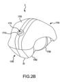
- FIG. 2B is a side top isometric view of the surgical guide tool 5 of FIG. 2A , wherein the tool 5 is in a non-customized state or is in the form of a blank from which a customized tool 5 is generated via an automated manufacturing machine, such as, for example, a CNC milling machine.
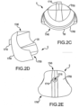
- FIGS. 2C-2E are front, side and top plan views, respectively, of the tool 5 of FIG. 2B .
- FIG. 2F is the same view as FIG. 2B , except the tool 5 is in the customized state depicted in FIG. 2A and a saw slot 1725 is shown.
- FIG. 2G is a side bottom isometric view of a version of the tool 5 depicted in FIG. 2F , except the tool 5 of FIG. 2G employs a planar surface 1725 as the saw guide 1725 in place of the saw slot 1725 depicted in FIG. 2F , the mating region 20 of the tool 5 of FIG. 2G being configured to engage the mating region of the femur 40 depicted in FIG. 13 .
- FIG. 2H is a cross section taken through section line 2H-2H, which extends generally posterior-anterior in FIG. 2A , except employing the version of the tool 5 depicted in FIG. 2G .
- the surgical guide tool 5 includes a proximal or head end 1745, a distal or greater trochanter end 1750, a top side 1755 and a bottom side 1760.
- the bottom side 1760 and the top side 1755 are generally arcuately shaped.
- the width of the tool 5 may gradually increase from the proximal end 1745 to the distal end 1750.
- the ends 1745, 1750 are formed or otherwise joined together via the bottom side 1760 and top side 1755 such that the tool 5 may be a single-piece tool having a single-piece construction that is generally unitary and continuous in nature.
- the tool 5 may have a multi-piece construction, for example, where the saw guide is mounted as a separate and independent piece on the rest of the tool that includes the mating region.
- the tool 5 may be made of polyoxymethylene (acetal resin), a low density polyethylene, or other biocompatible plastics.
- portions of the bottom side 1760 and the top side 1755 may include a customizable mating or indexing region 20 that may have mating contact surfaces 708a, 710a and non-contacting surfaces 718a, 720a defined therein.
- the mating or indexing region 20 may be adapted to matingly receive regions of the proximal femur 40 having mating contact surfaces 708, 710 and non-contacting surfaces 718, 720 such as those discussed in detail later this Detailed Description with respect to FIG. 13 or similar to those discussed in detail with respect to FIGS. 14A-16B .
- the region of the femur 40 which may be matingly received by the tool mating region 20 when the tool 5 is mounted on the femur 40, may include a mating contact surface 708 covering portions of the posterior region of the neck 35 and a mating contact surface 710 that is a narrow band following along the intertrochanteric crest 116.
- the mating contact surfaces 708a, 710a of the tool mating region 20 may be configured to matingly contact the mating contact surfaces 708, 710 of the femur 40 when the tool mating region 20 matingly receives therein the region of the femur that has the mating contact surfaces 708, 710.
- the femur surfaces 708, 710 to be mated or indexed by the tool mating or index surfaces 708a, 710a may be separated by non-contacting surfaces 718, 720 of the femur 40.
- the non-contacting surfaces 718, 720 of the femur 40 may be spanned in a spaced-apart, non-contacting arrangement by non-contacting surfaces 718a, 720a of the tool mating region 20 when the tool mating region 20 matingly receives the region of the femur 40 including the non-contacting surfaces 718, 720 and the tool mating surfaces 708a, 710a matingly contact the femur contacting surfaces 708, 710.
- the non-contacting surfaces 718a, 720a of the tool mating region 20 may be the result of an over-estimating process occurring during image segmentation as described later in this Detailed Description. As can be understood from FIG.
- the non-mating surfaces 718, 720 of the proximal femur 40 may include portions 718 of the posterior greater trochanter 115 and portions 720 of the trochanteric fossa 210 (i.e., the depression between the greater trochanter and the femur neck).
- the top side 1755 may include a fastener-receiving feature 1710.
- the fastener-receiving feature 1710 may be generally ring shaped and may include a hole 1715 extending axially therethrough.
- the top side 1755 includes one fastener-receiving feature 1710.
- the top side 1755 includes more than one fastener-receiving feature 1710.
- the fastener receiving feature 1710 is configured to receive a fastener 1716 through the hole 1715, thereby securing the tool 5 to the femur 40 when the indexing surfaces 708a, 710a of the tool mating region 20 matingly contact the corresponding bone surfaces 708, 710.
- the top face does not include a fastener receiving feature 1710 and the tool is secured by other methods, such as being held in place by the surgeon.
- the fastener 1716 may be a pin, screw or other suitable device.
- the top side 1755 may also include a saw guide 1725 that is configured to receive a saw blade during a THR.
- the saw guide 1725 may be in the form of a planar surface, a slot or any other feature capable of guiding a saw during a resection.
- the saw slot 1725 is generally an open-ended rectangle and extends axially through the tool 5 from the top side 1755 to the bottom side 1760.
- the saw slot 1725 may extend across the entire width of the neck 35 such that the surgeon may make a complete resection of the neck.
- the saw slot 1725 may extend at least partially across the width of the neck such that the surgeon may make a partial neck resection.
- the saw slot 1725 may be positioned in the tool 5 such that the slot 1725 is aligned with a preoperatively planned resection plane 805, as determined by 3D modeling.
- the resection plane 805 may correspond with a spacer region 803 of the femoral prosthetic implant or component 800 that limits the extent to which the femoral component may be inserted into the resected proximal femur during implantation.
- the resection plane 805 defines the location of the head and neck resection during surgery.
- the subsequent cut through the neck 35 of the proximal femur 40 will expose a portion of the neck 35 for receipt of the femoral component 800. Because the location of the saw slot 1725 is determined based on preoperative planning employing 3D models of the patient's femur and the specific implant 800 to employed in the THR, the subsequent cut through the neck is positioned to expose a portion of the neck aligned to receive the femoral component 800 such that the femoral component 800 may be accurately positioned upon insertion into the femur.
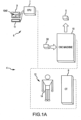
- the above-described customized guide tool 5 may be designed and manufactured employing a system 4 similar to that schematically depicted in FIG. 1A .
- the system 4 may include a preoperative planning system 6 in the form of a computer 6 having a CPU 7, a monitor or screen 9 and operator interface controls 11, such as a keyboard, mouse, etc.
- the computer 6 may be linked to a medical imaging system 8, such as a CT or MRI machine 8, and an automated or rapid manufacturing machine 10, such as a stereolithography apparatus ("SLA”) or a computer numerical controlled (“CNC”) milling machine 10.
- SLA stereolithography apparatus
- CNC computer numerical controlled
- the imaging machine 8, the manufacturing machine 10, and the modeling system 6 of the system 4 may be in communication with each other via, for example, hardwire, internet, wireless, portable memory devices or any combination thereof.
- the medical imaging machine 8 may be employed to generate medical images 500 of the joint 14 of the patient 12 that is the subject of the arthroplasty. While this Detailed Description is given in the context of the joint 14 being a hip joint 14 and the tool 5 being configured for the preparation of the proximal femur 40 to receive a total hip replacement prosthetic implant, the concepts disclosed herein may be readily applicable to arthroplasty for other types of joints, including, for example, ankles, knees, wrists, elbows, shoulders, vertebra, fingers, toes, etc. Any resulting 2D medical images 500 may be sent to the computer 6 for use in the preoperative planning.
- an operator may view the various 3D computer generated models, such as the femur model 1040 and others, via the monitor 11 as the operator interacts with the computer 6 via the controls 11 to direct the preoperative planning.
- Computer programs for creating, storing and manipulating the various 3D computer generated models may be stored in computer memory accessible by the CPU 7.
- Computer programs for creating the 3D computer generated bone model 1040 from the 2D images 500 include: Analyze from AnalyzeDirect, Inc., Overland Park, KS; Insight Toolkit, an open-source software available from the National Library of Medicine Insight Segmentation and Registration Toolkit ("ITK"), www.itk.org; 3D Slicer, an open-source software available from www.slicer.org; Mimics from Materialise, Ann Arbor, MI; and Paraview available at www.paraview.org.
- ITK National Library of Medicine Insight Segmentation and Registration Toolkit
- the resulting information is used to create manufacturing instructions that are sent to the automated manufacturing machine 10 to generate the final tool 5, which in some embodiments, may be manufactured from a tool blank 50 placed in the manufacturing machine 10.
- FIG. 1B is a diagrammatic depiction of the tool planning process, beginning with the generation of the 2D medical images 500 and ending with the manufacturing instructions being sent to the CNC machine 10.
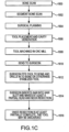
- FIG. 1C is a flow chart extending from the generation of the 2D medical images 500, through the planning and manufacturing of the tool 5, and finishing with the tool 5 being employed in the arthroplasty procedure.
- a patient 12 has a hip joint 14 that is the subject of a THR surgery.
- the hip joint 14 of the patient 12 is scanned in the imaging machine 8 [block 1500 and block 1600].
- the scanning may include up to one-third of the proximal femur 40, including the femoral head 30 and the lesser trochanter 746. In other embodiments, the scanning may include a greater or lesser portion of the femur.
- the resolution of a CT scan or an MRI scan is greater than the resolution of x-ray. Greater resolution leads to more accuracy in the preoperative planning process, which leads to greater precision in the resulting tool 5.
- the resolution of the scan is between approximately 0 mm and approximately 2 mm. In other embodiments, the resolution of the scan is between approximately 0.3 mm and approximately 0.6 mm. In one embodiment, a CT scan with a resolution of approximately 0.6 mm is utilized for creation of the tool.
- a CT scan with a resolution of approximately 0.5 mm to 2 mm, with a tube current ranging from 200 mA to 400 mA and a tube voltage ranging from 120kV to 140kV and a direct field of view (“DFOV”) ranging from approximately 16 cm to approximately 26 cm is utilized for creation of the tool.
- DFOV direct field of view
- the imaging machine 8 makes a plurality of scans of the joint 14, wherein each scan pertains to a thin 2D image slice 500 of the joint 14.
- the plurality of 2D images 500 which may be CT, MRI or other 2D medical images, are sent from the imaging machine 8 to the preoperative planning system 6.
- the 2D images are subjected to an image segmentation process, wherein the bone contour lines 502 are identified in each of the images 500 [block 1500 and block 1602].
- the bone surface contour lines of the femur 40 depicted in the image slices 500 may be auto segmented via a image segmentation process as disclosed in U.S. Patent Application 61/126,102, which was filed April 30, 2008 , is entitled System and Method for Image Segmentation in Generating Computer Models of a Joint to Undergo Arthroplasty, and is hereby incorporated by reference into the present application in its entirety.
- the bone scan may be sectioned for the segmentation process at an angle Z.
- image segmentation is performed utilizing image slices or sections 500 at an angle Z off the central axis 100 of the femoral neck 35 viewed posteriorly.
- the segmentation can be done in several ways and for ease of the reader are described in relation to a CT-scan.
- the CT locator could be positioned at an angle Z to section the CT scan.
- the CT scan could be sectioned at an angle Z during post-processing.
- the angle Z is between approximately thirty degrees and approximately sixty degrees. In an alternative embodiment, the angle Z is approximately a 45 degree angle. It can be appreciated that segmentation of an MRI scan may be achieved in a similar manner.
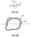
- FIGS. 4A-6B are 3D views of the proximal femur 40 respectively showing section or scan planes A, B and C extending through the femur 40.
- FIGS. 4B , 5B and 6B are respectively the segmented image slices of planes A, B and C, respectively.
- section or scan plane A extends through the proximal femur generally transverse to the femoral axis and just distal of the lesser trochanter.
- the contour line 601 corresponding to the cortical bone and the contour line 602 corresponding to the trabecular bone 602 may be identified.
- section or scan plane B extends through the proximal femur generally transverse to the femoral axis and approximately midway between the tip of the greater trochanter and the lesser trochanter.
- the contour line 601 corresponding to the cortical bone and the contour line 602 corresponding to the trabecular bone 602 may be identified.
- section or scan plane C extends through the proximal femur generally transverse to the femoral axis and just distal the tip of the greater trochanter.
- the contour line 601 corresponding to the cortical bone and the contour line 602 corresponding to the trabecular bone 602 may be identified.
- the region of the femur 40 which may be matingly received by the tool mating region 20 when the tool 5 is mounted on the femur 40, may include a mating contact surface 708 covering portions of the posterior region of the neck 35 and a mating contact surface 710 that is a narrow band following along the intertrochanteric crest 116.
- the femur mating contact surfaces 708, 710 may be separated by non-contacting surfaces 718, 720 of the femur 40.
- the non-contacting surfaces 718, 720 of the proximal femur 40 may include portions 718 of the posterior greater trochanter 115 and portions 720 of the trochanteric fossa 210.
- the portions 708P, 710P of the cortical bone contour lines 601 in FIGS. 5B and 6B correspond to the mating contact surfaces 708, 710 of the femur 40
- the portions 718P, 720P of the cortical bone contour lines 601 in FIGS. 5B and 6B correspond to the non-contact surfaces 718, 720 of the femur 40.
- the cortical contour line 601 depicted in FIG. 4B is from a slice that would be located below the tool mating regions of the femur 40. Therefore, this contour line 601 depicted in FIG. 4B does not have portions 718P, 720P, 708P, 710P.
- the non-contact portions 718P, 720P of the cortical bone contour lines 601 correspond to surfaces 718, 720 of the femur 40 that are difficult to replicate in the tool mating region 20 due to the extreme variance in surface topography for the surfaces 718, 720.
- other difficult to replicate surfaces that surfaces portions 718P, 720P may correspond to may include surfaces of osteophytes or other bone surface irregularities.
- corresponding regions of the tool mating region 20 would be difficult to machine to correspond to the surfaces 718, 720 of the femur 40 due to limitations in the milling process; or (2) the surfaces 718, 720 would be difficult to model because of limitations in the scanning or 3D computer modeling processes.
- the difficult to replicate contour line portions 718P, 720P may be subjected to an overestimation process. Specifically, the difficult to replicate contour line portions 718P, 720P are modified to be extended outwardly away from the interior of the bone (i.e., over-estimated) and, in some instances smoothed with respect to shape.
- the resulting cortical bone contour lines 601 now include the original portions 708P, 710P in their original shape and location and the now overestimated or outwardly adjusted portions 718P, 720P; these resulting cortical bone contour lines 601 from each image slice are then compiled or reconstructed into the 3D computer generated femur model 1040 used for the preoperative planning process.
- the end result of the overestimation process with respect to the manufacture of the completed tool 5 is that the CNC tool paths corresponding to the overestimated regions of the femur model 1040 remove excess materials from the mating region 20 of the blank used to form the tool 5.
- the tool mating region 20 is configured to matingly contact only with those surfaces 708, 710 of the femur that can be accurately replicated in the tool mating region 20, and those surfaces 718, 720 that cannot be accurately replicated in the tool mating region 20 are not contacted by any surface of the tool mating region 20 because the tool mating region 20 has been over-milled in the areas of the tool mating region 20 corresponding to the difficult to replicate femur surfaces 718, 720.
- the result is a tool 5 with a mating region 20 that accurately mates to the mating region of the femur 40.
- the line contours 601 for the cortical bone may be subjected to overestimation while the line contours 602 for the trabecular bone are not subjected to overestimation.
- the contour lines 601, 602 for both the cortical and trabecular bones are subjected to overestimation.
- the cortical bone contour lines 601 may be employed to generate a 3D computer generated cortical bone model
- the trabecular bone contour lines 602 may be employed to generate a 3D computer generated trabecular bone model.
- the cortical bone model and the trabecular bone model may be combined into a single 3D computer generated femur model 1040 [block 1501], as depicted in FIG. 9A discussed below.
- FIG. 9A which is a posterior view of the femur model 1040
- the contour lines may be imported into a 3D computer modeling program.
- the model program may then be used to generate 3D computer models of the cortical bone 601 and the trabecular bone 602 of the proximal femur 40.
- the model of the trabecular bone 602 may be subtracted from the model of the cortical bone 601 to create a hollow 3D computer generated femur model 1040, wherein the subtracted model of the trabecular bone 602 creates a hollow region of the femur model 1040 that represents the medullary canal 170.
- FIG. 7 which is an example superior view CT scan of the proximal femur 40 of FIG. 2A
- the CT scan may be reconstructed for proper coronal alignment by causing the coronal slices to be parallel to the femoral neck 35.
- the slice width and overlap may range from approximately 0.5 mm to approximately 2 mm. In one embodiment, a slice width and overlap of 0.5 mm is used.
- the DFOV may range between approximately 16 cm to approximately 26 cm field of view.
- the reformatted CT scan may include up to one-third of the proximal femur 40, including the femoral head 30 and the lesser trochanter 746. In other embodiments, the CT scan may include a greater or lesser amount of the proximal femur.
- FIG. 8 which is an example CT scan of the proximal femur 40 of FIG. 2A , wherein the proper alignment for the final CT reconstruction is shown from a coronal slice.
- the final reconstruction alignment 1760 is set to an angle Q relative to the long axis 1761 of the femoral neck 35.
- Angle Q may range from approximately 30 degrees to approximately 60 degrees. In one embodiment, angle Q is 45 degrees.
- the slice width and overlap may range from approximately 0.5mm to approximately 2 mm. In one embodiment, the slice width and overlap is 1mm.
- the field of view may range from approximately 16mm to approximately 26 mm.
- the scan may include up to one-third of the proximal femur 40, including the femoral head 30 and the lesser trochanter 746. In other embodiments, the CT scan may include a greater or lesser amount of the proximal femur.
- the preoperative planning process may begin [block 1604], wherein the 3D bone model is utilized to determine: (1) the proper size and placement of a femoral component (e.g.
- the following preoperative planning methods may employ a 3D computer modeling program, such as, for example, Solidworks or Paraview, in the generation, placement, manipulation, determination and importation of various 3D computer models described below.
- the preoperative planning may begin with the femur model 1040, a 3D computer generated sphere model 701, and a 3D computer generated rod model 702 being imported into a modeling space [block 1502].
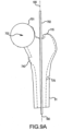
- FIGS. 1B and FIGS. 9A and 9B are respective transparent posterior and superior views of a 3D computer generated model 1040 of the proximal femur 40 of FIG. 2A
- the preoperative planning may begin with the femur model 1040, a 3D computer generated sphere model 701, and a 3D computer generated rod model 702 being imported into a modeling space [block 1502].
- the femur model 1040 which is a result of the compiled or reconstructed contour lines, some of which may have been overestimated, may have a head 30, a neck 35, a shaft 51, a greater trochanter, and an medullary canal 170.
- the models 701, 702, 1040 are combined together in a superpositioned arrangement.
- the rod model 702 may be positioned so that it generally aligns with the center of the medullary canal 170 of the shaft of the femur model 1040, which generally corresponds to a central axis 100 of the shaft of the femur.
- the rod 702 may be positioned to be generally coaxial with the femur axis 100.
- the sphere model 701 may be positioned so the centers of the sphere 701 and head 35 are located at the same point.
- the diameter of the sphere model 701 may be increase or decreased to cause the sphere model 701 to generally approximate the femoral head 30 such that the hemispherical surfaces of the head 30 and the sphere 701 are generally coextensive for a significant portion of the hemispherical surface of the head 30.
- the damage is typically to the superior and anterior surfaces, so the sphere 701 is typically positioned and sized such that hemispherical surface of the sphere 701 is generally coextensive with the inferior and posterior regions of the head 30.
- the center 703 of the sphere 701 will generally approximate the center of the hip joint.
- the proper positioning and sizing of the models 701, 702 can be verified by looking at both posterior ( FIG. 9A ) and superior ( FIG. 9B ) views.
- a 3D computer generated femoral component model 850 may be imported into the modeling space [block 1503].
- the femoral component model 850 may include a shaft 804, a head 802 and a spacer region 801.
- the spacer region 801 may have a surface 803 that abuts against the surface of the bone resection when the actual implant is properly and fully implanted in the resected femur.
- the 3D femoral component model 850 may be selected from a database of femoral component models, the models in the data base corresponding to the sizes of femoral components available from a selected manufacturer. Size selection is based on the shape and size of the medullary canal 170. Once the position of the neck resection has been determined, the largest component that fits within the canal is chosen.
- the sphere model 701 and rod model 702 are used to plan the proper alignment and placement of the femoral component model 850.
- the femoral component model 850 may be superimposed with the rest of the models 701, 702, 1040 such that the long axis of the shaft 804 of the component 800 generally corresponds to the long axis of the rod 702 in a generally coaxial manner, and the center of the head 802 of the component model 850 generally corresponds to the approximated hip joint center 703.
- the size and the shaft to neck angle of the spacer 801 may be adjusted according to the ranges available from the manufacturer for the femoral component.
- the above-described embodiment superimposes the sphere and rod models 701, 702 on the femur model 1040 prior to superimposing the femoral component model 850 and using the sphere and rod model locations to position and size the femoral component model 850.
- the femoral component model 850 may be superimposed on the femur model 1040 for positioning and sizing without the presence and use of the sphere and rod models 701, 702.
- FIGS. 1B and 1C and FIG. 10 which is an isometric posterior view of the femoral model 1040 of FIG. 9C , except with the other models 701, 702, 850 hidden for clarity purposes, a 3D computer generated tool blank model 550 is generated [block 1504] and imported into the modeling space to be superpositioned with the femoral model 1040 to define the mating region 20 and saw guide 1725 in the tool blank model 550 [block 1505 and 1606].
- the tool blank model 550 is positioned over the posterior surface of the femur model 1040 such that: (1) the surfaces of the femur model 1040 corresponding to the mating contact surfaces 708, 710 and non-contact surfaces 718, 720 of the femur 40, as discussed in detail below with respect to FIG. 13 , are covered by the tool 5; and (2) the head 30 of the femur model 1040 is exposed.
- FIG. 11 which is a inferior-posterior isometric view of what is depicted in FIG. 10
- a distal portion 1750 of the tool blank model 550 may be removed to provide a non-contacting arrangement between the resulting tool 5 and non-mating regions of the proximal femur 40, such as those regions near the greater trochanter 115.
- FIGS. 1B and 1C and FIG. 12 which is generally the same view as FIG. 11 , except the femoral component model 850 is visible and the tool blank model 550 is now a customized tool model 603, once the tool blank model 550 is properly positioned on the femur model 1040, the tool mating region 20 and saw guide 1725 may be defined and imported into the tool blank model 550 to create the tool model 603 [block 1506 and block 1606]. Specifically, those mating contact surfaces 708a, 710a and non-contacting surfaces 718a, 720a of the tool mating region 20 that respectively correspond to the contact surfaces 708, 710 and non-contact or overestimated surfaces 718, 720 of the femur 40 of FIG.
- the contacting surfaces 708, 710 and non-contacting surfaces 718, 720 of the femur model 1040 may be identified and defined as 3D surface models 537, 539 or other types of "data" that are imported into the tool blank model 550 to create the contacting surfaces 708a, 710a and non-contacting surfaces 718a, 720a in the mating region of the tool blank model 550 [block 1506].
- the surface 803 of the spacer region 801 of the component model 850 may be coplanar to the resection plane 805 needed to allow the actual implanted femoral component to achieve the implant positioning that will achieve the predicted desirable surgical outcome.
- the spacer region surface 803 will correspond to the position and orientation of the resection plane 805 when the component model 850 is properly positioned in the femur model 1040.
- the position and orientation of the spacer region surface 803 may be used to define the position and orientation of the resection plane 805 and, as can be understood from FIG. 1B , a resection plane model 538 or other types of "data" may be defined and imported into the tool blank model 550 to define the saw guide 1725 in the tool blank model 550 [block 1506]. Since the location and orientation of the surface models 539, 537 and plane model 538 may be referenced relative to each other due to the femur, component and blank models 1040, 805, 550 being superimposed with each other, the position and orientation relationships are maintained in the resulting tool model 603 [block 1507].
- the saw guide 1725 may be positioned and oriented relative to the customized mating or indexing region 20 such that, when the mating surfaces 708a, 710a of the mating region 20 matingly contact the bone surfaces 708, 710 when the tool mating region 20 matingly receives therein the region of the femur 40 having the bone surfaces 708, 710, the saw guide 1725 may be oriented over the femur neck 35 such that the saw guide 1725 corresponds with a desired resection plane 805 through the femoral neck 35 that was identified during the preoperative planning.
- the cavity or mating region 20 of the tool 5 conforms to the segmented CT scans or MRI scans, overestimated as necessary, of the patient's femur, and the saw guide 1725 is positioned so as to result in a preoperatively planned resection of the proximal femur when the tool mating region 20 matingly engages the proximal femur and a sawing action is guided by the saw guide 1725.
- Proper alignment of the saw slot 1725 with the preoperatively planned resection plane exposes the femoral neck to provide a properly oriented surface for proper alignment of the femoral component.
- a properly positioned femoral component prevents or at least minimizes the chances of several undesirable complications. For example, an improperly positioned femoral component can cause a change of leg length, dislocation of the hip or perforation of the femur.
- the tool model 603 may be used to generate automated manufacturing instructions (e.g., tool paths, etc.).
- the tool model 603 or automated manufacturing instructions are sent to the CNC machine 10 from the preoperative planning system 6 [block 1508], and the actual tool 5 is manufactured from an actual tool blank 50 via the CNC machine 10 [block 1608].
- the finished tool 5 may be marked with patient data (e.g., name, hip identification, etc.), surgeon name, medical facility name, or other information.
- the tool 5 may then be sterilized, packaged and sent to the surgeon [block 1610].
- the surgeon may fit the tool appropriately on the femur and, in one embodiment, drill into the hole 1715 of the fastener feature 1710 at the top side 1755 of the tool and insert a fastening member 1716 to stabilize the tool [block 1612].
- the tool 5 may be held in place by the surgeon or other medical personnel. Once positioned, the surgeon may place a saw blade through the saw slot 1725 and prepare to saw through the resection plane to make at least a partial head and neck resection [block 1614]. Once the resection is at least partially complete, the tool may be discarded [block 1616]. In some embodiments, the tool 5 may remain in place until the resection is complete.
- the surgeon may then further prep the resected proximal femur and then implant the femoral component 800 in a manner that replicates the preoperative planning such that the surface 803 abuts against the resection surface of the femur.
- the tool 5 is custom configured to facilitate the preoperatively planned positioning of the femoral component
- the tool 5 disclosed herein facilitates HRS that is substantially more likely to result in a positive surgical outcome for the patient as compared to conventional methods that rely on x-rays, hand measuring techniques and surgeon visual assessment.
- the tool 5 decreases the risks commonly associated with an improperly placed femoral component in total hip replacement surgery, such as dislocation of the hip, a change in the length of the leg or perforation of the femur.
- the surgical time is substantially reduced because the surgeon simply has to cause the tool 5 to engage the proximal femur, as opposed to determining the proper location for the resection based off of visual inspection at the time of surgery.
- the tool 5 aids the surgeon in accurately and quickly placing the femoral component 800.
- the tool 5 also decreases the risks associated with the length of the surgical time, such as, infection, excessive bleeding, etc.
- the above-described POP procedure is a manual process, wherein computer generated 3D models 701, 702, 1040, 850 are manually manipulated relative to each other by a person sitting in front of a computer 6 and visually observing the 3D models 701, 702, 1040, 850 on the computer screen 9 and manipulating the 3D models 701, 702, 1040, 850 via the computer controls 11.
- the POP process is generally or completely automated.
- a computer program may manipulate computer generated 3D models 701, 702, 1040, 850 relative to each other to preoperatively plan the tool 5.
- the above-described POP process may have portions that are generally manual while other portions that are generally automated.
- the mating region 20 of the tool 5 may be customized based on a patient's individual bone shape.
- the tool 5 may be machined, molded or otherwise formed from the non-customized state as illustrated in FIGS. 2B-2E to a customized state as indicated in FIGS. 2F-2H , based on a patient's individual bone scan, for example an MRI scan or CT-scan.
- the bone scan data may be utilized to generate a 3D computer generated model 1040 of the patient's proximal femur 40.
- a 3D computer generated model 550 of the blank of the tool 5, the 3D femur model 1040, and 3D computer generated models of the implant component 850, the sphere 701, and the rod 702 may be superimposed and aligned as described above to preoperatively plan the patient specific tool 5. That is, through the information received from the MRI scan or CT-scan and the computer modeling, the tool 5 may be customized at the mating region 20 such that the tool 5 will have mating or indexing surfaces 708a, 710a of the mating region 20 that generally conform to the predetermined specific surface geometry of the patient's own proximal femur 40. In some embodiments, the predetermined specific geometry will be that of surfaces 708, 710 discussed with respect to FIG.
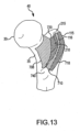
- FIG. 13 which is a posterior medial view of the proximal femur 40 of FIG. 2A showing the surfaces 708, 710 of the femur 40 that are mated with the index surfaces 708a, 710a of the tool mating region 20 and the surfaces 718, 720 that correspond to over-estimated or non-contacting surfaces 718a, 720a of the tool mating region 20.
- the femur mating region depicted in FIG. 13 may be applicable to a posterior approach to help with stable positioning of the tool 5 on the femur 40.
- a first mating surface 708 covers portions of the posterior region of the neck 35, starting medially between approximately 1 mm and approximately 5 mm after the cartilage covering the head 30 of the femur 40 terminates laterally and laterally extends between approximately 15 mm and approximately 35 mm to or towards the trochanteric fossa 210.
- the inferior boundary of surface 708 may terminate approximately 5 mm superior to the inferior border between the posterior and anterior surfaces of the neck 35, or may extend up to approximately 5 mm anterior past this border.
- the superior boundary of mating surface 708 may extend approximately 0 mm to approximately 5 mm posterior to the superior junction between the posterior surface and the anterior surface of the neck 35.
- a second mating surface 710 may be a narrow band measuring between approximately 0.5 mm and approximately 12 mm medial-lateral. The second mating surface 710 may follow along the intertrochanteric crest 116. Mating surface 710 may begin approximately 0 mm to approximately 12 mm superior to the lesser trochanter 740 and may extend approximately 0 mm to approximately 18 mm inferior to the most superior tip 215 of the posterior surface of the greater trochanter 115.
- mating surfaces 708, 710 of the femur 40 may be used to define the mating contact surfaces 708a, 710a of the tool mating region 20 (see FIG. 2G ) such that the tool contact surfaces 708a, 710a may matingly contact the femur surfaces 708, 710 when the tool mating region 20 mating receives or engages the femur 40 as depicted in FIG. 2H .
- a first non-mating surface 718 may include portions of the posterior greater trochanter 115 and extend superior-inferior adjacent the intertrochanteric crest 116.
- the medial boundary of the first non-mating surface 718 may be the second mating surface 710, and may extend medial-lateral approximately 0mm to approximately 12 mm.
- the second non-mating surface 20 may span portions of the trochanteric fossa 210, and may have a medial boundary that is the first mating surface 708 and a lateral boundary that is the second mating surface 710, and a medial-lateral width that may vary between approximately 0mm and approximately 20 mm. Both the first non-mating surface 718 and the second non-mating surface 720 may have inferior-superior dimensions similar to the first mating surface 708 and the second mating surface 710.
- contour line portions corresponding to non-mating surfaces 718, 720 and osteophytes may be overestimated (e.g., moved outward from the interior of the bone and smoothed) such that portions of the tool mating region 20 defined according to those overestimated contour line portions are over-machined, ensuring that little or no contact occurs between the resulting non-mating surfaces 718a, 720a of the tool mating region 20 (see FIG. 2G ) and the corresponding non-mating surfaces 718, 720 of the bone when the tool mating region 20 matingly receives the region of the femur 40 having the non-mating surfaces 718, 720, as shown in FIG. 2H .
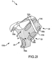
- the femur 40 may include contact surfaces 708, 710 and non-contact surfaces 718, 720 such that a tool 5 configured for a posterior approach may have a mating region 20 configured to have corresponding mating contact surfaces 708a, 710a and non-contacting surfaces 718a, 720a, as indicated in FIGS. 2G and 2H .
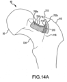
- the tool mating region 20 may be such that the mating contact and non-contact surfaces of the tool mating region 20 are configured to correspond to mating and non-contact surfaces of other regions of the femur 40 as described below with respect to FIGS. 14A-14B , 15 and 16A-16B .
- the mating region of the femur 40 may be appropriate for a posterior or anteriorlateral surgical approach.
- the mating region of the femur 40 may include mating surfaces 700a, 701a, 702a, 704a.
- FIG. 21 which is a view similar to FIG. 2G , except of a tool mating region 20 configured to matingly engage the mating surfaces 700a, 701a, 702a, 704a depicted in FIGS.
- the mating surfaces 700a, 701a, 702a, 704a of the femur 40 may be matingly contacted by corresponding mating or index contact surfaces 700b, 701b, 702b, 704b of the tool mating region 20 to help stabilize the positioning of the tool 5 on the femur 40.
- the tool mating region 20 depicted in FIG. 2G is configured to matingly engage the mating surfaces of the femur 40 depicted in FIG. 13
- the tool mating region 20 depicted in FIG. 21 is configured to matingly engage the mating surfaces of the femur 40 depicted in FIGS. 14A-14B .
- a first mating surface 700a includes portions of the posterior region 724 of the neck 35, having a medial starting point between approximately 1 mm and approximately 5 mm after the cartilage covering the femoral head 30 terminates laterally and extends laterally between approximately 15 mm and approximately 35 mm to or towards the trochanteric fossa 210.
- the inferior border of the first mating surface 700a begins approximately midway superiorly-inferiorly along the intertrochanteric crest 116, and follows the long axis of the neck 35.
- the superior border of the first mating surface 700a is between approximately 1 mm and approximately 3 mm below the superior junction 728 between the posterior and anterior surfaces of the neck 35.
- a second mating surface 701a has approximately the same medial-lateral width as section 700a, but may terminate before the tubercle 730 of the femur 40.
- the superior border of the second mating surface 701a is approximately 1 mm to approximately 3 mm below the superior junction 728 between the posterior and anterior surfaces of the neck 35.
- the inferior-superior distance of second mating surface 701a is between 5 and 10 mm.
- a third mating surface 702a is a narrow band, measuring generally medial-lateral between approximately 0.5 mm and approximately 8 mm, that follows along the intertrochanteric crest 116.
- Mating surface 702a begins approximately midway superior-inferior along the intertrochanteric crest 116 and may extend any length greater than approximately 5 mm to or towards the most superior tip 215 of the posterior surface of the greater trochanter 115.
- a fourth mating surface 704a lies on the anterior greater trochanter 115, lateral to the tubercle 730 of the femur 40, and inferior to the origin of the obturator internus 732.
- the medial-lateral distance of mating surface 704a measures between approximately 3 mm to approximately 14 mm, and its inferior-superior distance measures between approximately 3 mm to approximately 10 mm.
- mating surfaces 700a, 701a, 702a, 704a may be separated by non-mating surfaces 712, 714, 716 that are spanned by and correspond respectively with non-contacting surfaces 22, 24, 26 of the mating region 20 of the tool 5 (see FIG. 21 ).
- a first non-mating surface 712 may include portions of the tubercle 730 of the femur 40.
- a second non-mating surface 714 may span portions of the trochanteric fossa 210.
- a third non-mating surface 716 may contain the superior junction 728 between the posterior and anterior surfaces of the neck 35, and may be between approximately 1mm to approximately 5 mm anterior-posterior.
- contour line portions corresponding to non-mating surfaces 712, 714, 716 may be overestimated (e.g., moved outward from the interior of the bone and smoothed) such that portions of the tool mating region 20 defined according to those overestimated contour line portions are over-machined, ensuring that little or no contact occurs between the resulting non-mating surfaces 22, 24, 26 of the tool mating region 20 (see FIG. 21 ) and the corresponding non-mating surfaces 712, 714, 716 of the femur 40 when the tool mating region 20 matingly receives the region of the bone having the non-mating surfaces 712, 714, 716.
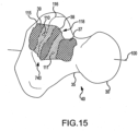
- FIG. 15 which is an isometric posterior view of the proximal femur 40, illustrates yet another mating region of the femur 40 that may be used to define the mating region 20 of another embodiment of the tool 5.
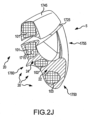
- FIG. 15 and FIG. 2J which is the same view as 2G, except of a tool 5 with a mating region 20 configured to matingly engage the mating region of the femur 40 depicted in FIG. 15 instead of the mating region of the femur 40 depicted in FIG.
- the tool mating region 20 may be adapted to receive therein and mate with surfaces of the proximal femur 40, such as, for example, the posterior region 37 of the neck 35, a medial posterior surface 38 of the greater trochanter 115 between the intertrochanteric crest 116 and trochanteric fossa 118, and a region 39 that is part of the lateral posterior greater trochanter 115 and the lateral posterior body of the femur bordering the lateral side of the intertrochanteric crest 116.
- surfaces of the proximal femur 40 such as, for example, the posterior region 37 of the neck 35, a medial posterior surface 38 of the greater trochanter 115 between the intertrochanteric crest 116 and trochanteric fossa 118, and a region 39 that is part of the lateral posterior greater trochanter 115 and the lateral posterior body of the femur bordering the lateral side of the intertrochanteric crest 116.
- the mating surface 37 may cover portions of the posterior region of the neck 35, starting medially between approximately 1 mm and approximately 5 mm after the cartilage covering the head 30 of the femur 40 terminates laterally and laterally extends between approximately 15 mm and approximately 35 mm to or towards the trochanteric fossa 118.
- Region 38 may be a band, extending from the lesser trochanter 740 to the anterior surface of the femur, and ranging in width from between approximately 0 mm to approximately 14 mm.
- the medial border of region 38 is the trochanteric fossa 118 and the lateral border is approximately the intertrochanteric crest 116.
- Region 39 begins medially at approximately the crest 116, and may extend from 0 mm to approximately the edge of the posterior surface of the femur 40.
- the inferior/superior length of region 39 may be 0 mm, or may extend from the lesser trochanter 740 to the superior border of the posterior surface of the femur 40.
- the surfaces 37, 38, 39 which are to be mated or indexed by the tool index surfaces 101, 102, 103 of the mating region 20 of the tool 5, may be separated by areas of non-mating surfaces 110, 111 that are spanned by overestimated or non-contacting surfaces 22, 24 of the mating region 20 of the tool 5.
- the non-contacting surfaces 22, 24 of the mating region 20 of the tool 5 do not contact the corresponding non-mating surfaces 110, 111 of the femur 40 and may be generated via an over-estimating process during image segmentation.
- the non-mating surfaces 110, 111 of the proximal femur 40 may be portions 111 of the trochanteric fossa 118 (i.e., the depression between the greater trochanter and the femur neck) and portions 110 of the intertrochanteric crest 116. More specifically, the non-mating surface or portion 111 may span portions of the trochanteric fossa 118, and may have a medial boundary that is the mating surface 37 and a lateral boundary that is the mating surface 38, and a medial-lateral width that may vary between approximately 0 mm and approximately 20 mm.
- Non-mating surface or portion 110 may be a band including the intertrochanteric crest 116, and may extend from the lesser trochanter 740 to the most superior point of the greater trochanter 115.
- the medial-lateral width of the surface 110 may be from approximately 0mm to approximately 12 mm.
- any surface of mating region 20 that is outside of tool mating surfaces 101, 102, 103 (which correspond to femur mating surfaces 37, 38, 39, respectively) may be tool non-contacting surfaces 22, 24, which correspond, respectively to femur non-contacting surfaces 110,111.
- the tool may be placed on the femur 40 such that the mating region 20 of the tool 5 covers and matingly receives the femur area encompassing the mating surfaces 37, 38, 39 and non-mating surfaces 110, 111 of the proximal femur 40.
- non-mating regions 110, 111 including portions of the trochanteric fossa 118 (the depression between the greater trochanter and the neck of femur) and the intertrochanteric crest 116, are not easily estimated due to drastic changes in surface geometry, and corresponding non-mating surfaces 22, 24 of the mating region 20 of the tool 5 do not contact these surfaces 110, 111 when the region of the femur that includes the femur mating surfaces 37, 38, 39 and non-mating surfaces 22, 24 are matingly received by the mating region 20 of the tool 5.
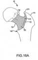
- the mating region of the femur 40 may be configured for use with any surgical approach, and, in a manner similar to that discussed above with respect to FIGS. 2G-2H and 13 and FIGS. 2I and 14A-14B , the tool mating region 20 may be configured to matingly engage the mating region of the femur 40 as depicted in FIGS. 16A-16B .
- a first mating surface 706 of the femur 40 may include the entire or any portion of the circumferential surface 734 of the neck 35.
- the mating surface 706 may start medially between approximately 1 mm and approximately 5 mm after the cartilage covering the head 30 of the femur 40 terminates laterally and extend laterally up to approximately 8 mm past the intertrochanteric crest 116, extending along the intertrochanteric crest 116 from the lesser trochanter 740 to or towards the tip 215 of the greater trochanter 115.
- the mating surface 706 may start medially between approximately 1 mm and approximately 5 mm after the cartilage covering the head 30 of the femur 40 terminates laterally and extend laterally up to approximately 8 mm laterally past the intertrochanteric line 738.
- the surface 706 may also contain the medial surface of the greater trochanter 115.
- portions within the mating surface 706 may be overestimated if geometry is too erratic for the surface to be accurately captured with the CT scan.
- Some such areas may include the trochanteric fossa 210, the superior junction 728 between the posterior and anterior surfaces of the neck 35, and the tubercle 730.
- the configuration of the mating region 20 of the tool 5 may be determined from and correspond to the specific surface geometry or topography of the surface of the femur 40 that corresponds to the surgical approach for which the tool 5 is being designed.
- the tool mating region 20 may be configured to have the contact and non-contact surfaces that correspond to at least some, if not all, of the contact and non-contact surfaces of the femur mating region discussed above with respect to FIG. 13 .
- the tool mating region 20 may be configured to have the contact and non-contact surfaces that correspond to at least some, if not all, of the contact and non-contact surfaces of the femur mating region discussed above with respect to FIGS. 14A-14B . In yet other embodiments, the tool mating region 20 may be configured to have the contact and non-contact surfaces that correspond to at least some, if not all, of the contact and non-contact surfaces of the femur mating region discussed above with respect to FIG. 15 . In still other embodiments, the tool mating region 20 may be configured to have the contact and non-contact surfaces that correspond to at least some, if not all, of the contact and non-contact surfaces of the femur mating region discussed above with respect to FIGS.
- the tool mating region 20 may be based off of the medical imaging scans take of the femur 40 and preoperatively planned via 3D computer generated models to have a customized engagement with the femur 40 when applied to the femur to guide a resection in a THR.
- the arrangement between the customized mating region 20 of the tool 5 and the saw guide 1725 may be such that when the mating region 20 matingly receives the mating region of the femur 40, the saw guide 1725 may cause a resection procedure guided by the guide 1725 to create a preoperatively planned resection of the femur 40.
- a arthroplasty tool 5 or surgical guide tool 5 are described in the context of a tool 5 for use in a total hip replacement procedure, the features, methods of determining proper placement of the prosthetic device and the mating surfaces and the generation thereof disclosed herein may be equally useful and applicable for use in total arthroplasty procedures in other joint contexts. Thus, the disclosure provided herein should be considered as encompassing tools and the generation thereof for any total arthroplasty procedures.
Landscapes
- Health & Medical Sciences (AREA)
- Engineering & Computer Science (AREA)
- Life Sciences & Earth Sciences (AREA)
- Surgery (AREA)
- Biomedical Technology (AREA)
- Veterinary Medicine (AREA)
- Public Health (AREA)
- General Health & Medical Sciences (AREA)
- Animal Behavior & Ethology (AREA)
- Heart & Thoracic Surgery (AREA)
- Orthopedic Medicine & Surgery (AREA)
- Nuclear Medicine, Radiotherapy & Molecular Imaging (AREA)
- Medical Informatics (AREA)
- Oral & Maxillofacial Surgery (AREA)
- Molecular Biology (AREA)
- Dentistry (AREA)
- Manufacturing & Machinery (AREA)
- Automation & Control Theory (AREA)
- General Physics & Mathematics (AREA)
- Physics & Mathematics (AREA)
- Quality & Reliability (AREA)
- Transplantation (AREA)
- General Engineering & Computer Science (AREA)
- Cardiology (AREA)
- Vascular Medicine (AREA)
- Robotics (AREA)
- Surgical Instruments (AREA)
- Prostheses (AREA)
Claims (12)
- Verfahren zur Herstellung eines chirurgischen Führungswerkzeugs (5) zur Verwendung bei Hüfttotalendoprothesenoperationen an einem proximalen Abschnitt eines Femurs (40) mit einem Kopf (30), einem sich distal von dem Kopf erstreckenden Hals (35) und einem distal von dem Kopf liegenden Flächenbereich, wobei das Verfahren Folgendes umfasst:a) Erzeugen von medizinischen Abbildungsdaten, die dem proximalen Abschnitt des Femurs zugeordnet sind,b) Verwenden der Abbildungsdaten zur Erzeugung eines dreidimensionalen computergenerierten Femurmodells (1040) des proximalen Abschnitts des Femurs,c) Bereitstellen eines dreidimensionalen computergenerierten Implantatmodells,d) Bereitstellen eines dreidimensionalen computergenerierten Werkzeugmodells mindestens eines Abschnitts mindestens eines chirurgischen Führungswerkzeugs und eines chirurgischen Führungswerkzeugrohlings,e) Übereinanderlegen des Femurmodells und des Implantatmodells,f) Übereinanderlegen des übereinandergelegten Femurmodells und Implantatmodells auf das Werkzeugmodell,g) Erzeugen von Herstellungsanweisungen per Computer aus den aus Schritt f ermittelten Daten,h) Einsetzen der Herstellungsanweisungen bei einer Herstellungsmaschine zum Produzieren eines chirurgischen Führungswerkzeugs, dadurch gekennzeichnet, dass das Verfahren ferner Folgendes umfasst:i) Bereitstellen eines dreidimensionalen computergenerierten Kugelmodells (701) und/oder eines computergenerierten Stangenmodells (702) sowie Übereinanderlegen des Kugelmodells auf das Femurmodell, so dass veranlasst wird, dass eine Mitte des Kugelmodells allgemein mit einer Mitte eines Kopfs des Femurmodells zusammenfällt, und/oder Übereinanderlegen des Stangenmodells auf das Femurmodell, so dass veranlasst wird, dass das Stangenmodells allgemein auf einen Schaft des Femurmodells ausgerichtet wird.
- Verfahren nach Anspruch 1, wobei das chirurgische Führungswerkzeug (5) aus einem chirurgischen Führungswerkzeugrohling erzeugt wird.
- Verfahren nach Anspruch 1, wobei das Implantatmodell einen Schaftabschnitt und einen Kopfabschnitt aufweist.
- Verfahren nach Anspruch 3, wobei Folgendes zum Übereinanderlegen des Femurmodells (1040) und des Implantatmodells gehört: Veranlassen, dass eine Mitte des Kopfs des Implantatmodells allgemein mit einer Mitte eines Kopfs des Femurmodells zusammenfällt, und Veranlassen, dass der Schaft des Implantatmodells allgemein auf einen Schaft des Femurmodells ausgerichtet wird.
- Verfahren nach Anspruch 1, wobei Folgendes zum Übereinanderlegen des übereinandergelegten Femurmodells (1040) und Implantatmodells auf das Werkzeugmodell gehört: Veranlassen, dass der Übereinanderlegungsort des Werkzeugmodells einer bei einem ausgewählten chirurgischen Ansatz einzunehmenden Werkzeugposition allgemein entspricht.
- Verfahren nach Anspruch 1, wobei Folgendes zum Übereinanderlegen des Femurmodells und des Implantatmodells gehört: Veranlassen, dass eine Mitte des Kopfs des Implantatmodells allgemein mit der Mitte des Kugelmodells zusammenfällt, und/oder Veranlassen, dass der Schaft des Implantatmodells allgemein auf das Stangenmodell ausgerichtet wird.
- Verfahren nach Anspruch 1, wobei die medizinischen Abbildungsdaten über MRT und/oder CT generiert werden.
- Verfahren nach Anspruch 1, wobei die Herstellungsmaschine eine CNC-Maschine (16) und/oder eine Stereolithographievorrichtung ist.
- Verfahren nach Anspruch 1, wobei die aus Schritt f ermittelten Daten eine Resektionsebene aufweisen, die einer planaren Fläche eines Abstandhalterbereichs des Implantatmodells entspricht.
- Verfahren nach Anspruch 9, wobei die aus Schritt f ermittelten Daten ferner eine Koppelfläche aufweisen, die einem von dem Werkzeugmodell kontaktierten Bereich des Femurmodells entspricht.
- Verfahren nach Anspruch 10, wobei die Koppelfläche und die Resektionsebene positionsmäßig aufeinander bezogen sind.
- Verfahren nach Anspruch 11, wobei die Koppelfläche und die Resektionsebene jeweils dazu dienen, eine Schaltfläche und eine Sägeführung (1725) in dem Werkzeug (15) zu definieren, wobei die Schaltfläche und die Sägeführung so ausgestaltet sind, dass die Sägeführung so positioniert wird, wenn die Schaltfläche das proximale Femur koppelnd kontaktiert, dass eine Resektion des proximalen Femurs entsprechend einer vor der Operation geplanten Resektion ermöglicht wird.
Applications Claiming Priority (5)
| Application Number | Priority Date | Filing Date | Title |
|---|---|---|---|
| US3267108P | 2008-02-29 | 2008-02-29 | |
| US10876108P | 2008-10-27 | 2008-10-27 | |
| US11123808P | 2008-11-04 | 2008-11-04 | |
| US12/391,008 US9408618B2 (en) | 2008-02-29 | 2009-02-23 | Total hip replacement surgical guide tool |
| PCT/US2009/034983 WO2009111216A1 (en) | 2008-02-29 | 2009-02-24 | Total hip replacement surgical guide tool |
Publications (3)
| Publication Number | Publication Date |
|---|---|
| EP2265194A1 EP2265194A1 (de) | 2010-12-29 |
| EP2265194A4 EP2265194A4 (de) | 2015-06-10 |
| EP2265194B1 true EP2265194B1 (de) | 2023-05-24 |
Family
ID=41013734
Family Applications (2)
| Application Number | Title | Priority Date | Filing Date |
|---|---|---|---|
| EP09718014.5A Withdrawn EP2265198A4 (de) | 2008-02-29 | 2009-02-24 | Chirurgisches führungswerkzeug zur wiederherstellung der hüftoberfläche |
| EP09718041.8A Active EP2265194B1 (de) | 2008-02-29 | 2009-02-24 | Chirurgisches führungsinstrument für hüftgelenkstotalersatz |
Family Applications Before (1)
| Application Number | Title | Priority Date | Filing Date |
|---|---|---|---|
| EP09718014.5A Withdrawn EP2265198A4 (de) | 2008-02-29 | 2009-02-24 | Chirurgisches führungswerkzeug zur wiederherstellung der hüftoberfläche |
Country Status (4)
| Country | Link |
|---|---|
| US (5) | US8734455B2 (de) |
| EP (2) | EP2265198A4 (de) |
| TW (2) | TW200950743A (de) |
| WO (2) | WO2009111216A1 (de) |
Families Citing this family (170)
| Publication number | Priority date | Publication date | Assignee | Title |
|---|---|---|---|---|
| US8801720B2 (en) | 2002-05-15 | 2014-08-12 | Otismed Corporation | Total joint arthroplasty system |
| PT1568671E (pt) * | 2004-02-24 | 2010-07-16 | Lafarge Platres | Processo e dispositivo para fabrico de um corpo cimentcio celular |
| US9808262B2 (en) | 2006-02-15 | 2017-11-07 | Howmedica Osteonics Corporation | Arthroplasty devices and related methods |
| CA2642615A1 (en) | 2006-02-15 | 2007-08-30 | Otismed Corp | Arthroplasty jigs and related methods |
| US8568487B2 (en) | 2006-02-27 | 2013-10-29 | Biomet Manufacturing, Llc | Patient-specific hip joint devices |
| US8535387B2 (en) | 2006-02-27 | 2013-09-17 | Biomet Manufacturing, Llc | Patient-specific tools and implants |
| US9339278B2 (en) | 2006-02-27 | 2016-05-17 | Biomet Manufacturing, Llc | Patient-specific acetabular guides and associated instruments |
| US9907659B2 (en) | 2007-04-17 | 2018-03-06 | Biomet Manufacturing, Llc | Method and apparatus for manufacturing an implant |
| US7967868B2 (en) | 2007-04-17 | 2011-06-28 | Biomet Manufacturing Corp. | Patient-modified implant and associated method |
| US8608748B2 (en) | 2006-02-27 | 2013-12-17 | Biomet Manufacturing, Llc | Patient specific guides |
| US9113971B2 (en) | 2006-02-27 | 2015-08-25 | Biomet Manufacturing, Llc | Femoral acetabular impingement guide |
| US9289253B2 (en) | 2006-02-27 | 2016-03-22 | Biomet Manufacturing, Llc | Patient-specific shoulder guide |
| US8133234B2 (en) * | 2006-02-27 | 2012-03-13 | Biomet Manufacturing Corp. | Patient specific acetabular guide and method |
| US8298237B2 (en) | 2006-06-09 | 2012-10-30 | Biomet Manufacturing Corp. | Patient-specific alignment guide for multiple incisions |
| US8473305B2 (en) | 2007-04-17 | 2013-06-25 | Biomet Manufacturing Corp. | Method and apparatus for manufacturing an implant |
| US8603180B2 (en) | 2006-02-27 | 2013-12-10 | Biomet Manufacturing, Llc | Patient-specific acetabular alignment guides |
| US9918740B2 (en) | 2006-02-27 | 2018-03-20 | Biomet Manufacturing, Llc | Backup surgical instrument system and method |
| US8864769B2 (en) | 2006-02-27 | 2014-10-21 | Biomet Manufacturing, Llc | Alignment guides with patient-specific anchoring elements |
| US9345548B2 (en) | 2006-02-27 | 2016-05-24 | Biomet Manufacturing, Llc | Patient-specific pre-operative planning |
| US9173661B2 (en) | 2006-02-27 | 2015-11-03 | Biomet Manufacturing, Llc | Patient specific alignment guide with cutting surface and laser indicator |
| US8407067B2 (en) | 2007-04-17 | 2013-03-26 | Biomet Manufacturing Corp. | Method and apparatus for manufacturing an implant |
| US8070752B2 (en) | 2006-02-27 | 2011-12-06 | Biomet Manufacturing Corp. | Patient specific alignment guide and inter-operative adjustment |
| US10278711B2 (en) | 2006-02-27 | 2019-05-07 | Biomet Manufacturing, Llc | Patient-specific femoral guide |
| US8858561B2 (en) | 2006-06-09 | 2014-10-14 | Blomet Manufacturing, LLC | Patient-specific alignment guide |
| US8282646B2 (en) | 2006-02-27 | 2012-10-09 | Biomet Manufacturing Corp. | Patient specific knee alignment guide and associated method |
| US8591516B2 (en) | 2006-02-27 | 2013-11-26 | Biomet Manufacturing, Llc | Patient-specific orthopedic instruments |
| US8377066B2 (en) * | 2006-02-27 | 2013-02-19 | Biomet Manufacturing Corp. | Patient-specific elbow guides and associated methods |
| US20150335438A1 (en) | 2006-02-27 | 2015-11-26 | Biomet Manufacturing, Llc. | Patient-specific augments |
| US8092465B2 (en) | 2006-06-09 | 2012-01-10 | Biomet Manufacturing Corp. | Patient specific knee alignment guide and associated method |
| US8241293B2 (en) * | 2006-02-27 | 2012-08-14 | Biomet Manufacturing Corp. | Patient specific high tibia osteotomy |
| US8608749B2 (en) | 2006-02-27 | 2013-12-17 | Biomet Manufacturing, Llc | Patient-specific acetabular guides and associated instruments |
| US9795399B2 (en) | 2006-06-09 | 2017-10-24 | Biomet Manufacturing, Llc | Patient-specific knee alignment guide and associated method |
| US7805853B2 (en) * | 2006-08-31 | 2010-10-05 | David H Littig | Transfemoral pelvic impression system |
| US8460302B2 (en) | 2006-12-18 | 2013-06-11 | Otismed Corporation | Arthroplasty devices and related methods |
| CN101854885B (zh) * | 2007-07-11 | 2016-09-14 | 史密夫和内修有限公司 | 用于在髋关节外科手术中确定骨钉放置的方法和装置 |
| US8831302B2 (en) | 2007-08-17 | 2014-09-09 | Mohamed Rashwan Mahfouz | Implant design analysis suite |
| US8265949B2 (en) | 2007-09-27 | 2012-09-11 | Depuy Products, Inc. | Customized patient surgical plan |
| WO2011106399A1 (en) | 2010-02-25 | 2011-09-01 | Depuy Products, Inc. | Customized patient-specific bone cutting blocks |
| US8357111B2 (en) | 2007-09-30 | 2013-01-22 | Depuy Products, Inc. | Method and system for designing patient-specific orthopaedic surgical instruments |
| EP2957243A1 (de) | 2007-09-30 | 2015-12-23 | DePuy Products, Inc. | Massgeschneidertes patientespezifisches orthopädisches chirurgisches instrument |
| US9138239B2 (en) | 2007-09-30 | 2015-09-22 | DePuy Synthes Products, Inc. | Customized patient-specific tibial cutting blocks |
| US9173662B2 (en) | 2007-09-30 | 2015-11-03 | DePuy Synthes Products, Inc. | Customized patient-specific tibial cutting blocks |
| US8460303B2 (en) | 2007-10-25 | 2013-06-11 | Otismed Corporation | Arthroplasty systems and devices, and related methods |
| USD642263S1 (en) | 2007-10-25 | 2011-07-26 | Otismed Corporation | Arthroplasty jig blank |
| US10582934B2 (en) | 2007-11-27 | 2020-03-10 | Howmedica Osteonics Corporation | Generating MRI images usable for the creation of 3D bone models employed to make customized arthroplasty jigs |
| US8715291B2 (en) | 2007-12-18 | 2014-05-06 | Otismed Corporation | Arthroplasty system and related methods |
| US8777875B2 (en) | 2008-07-23 | 2014-07-15 | Otismed Corporation | System and method for manufacturing arthroplasty jigs having improved mating accuracy |
| US8221430B2 (en) | 2007-12-18 | 2012-07-17 | Otismed Corporation | System and method for manufacturing arthroplasty jigs |
| US8737700B2 (en) | 2007-12-18 | 2014-05-27 | Otismed Corporation | Preoperatively planning an arthroplasty procedure and generating a corresponding patient specific arthroplasty resection guide |
| US8545509B2 (en) * | 2007-12-18 | 2013-10-01 | Otismed Corporation | Arthroplasty system and related methods |
| US8480679B2 (en) | 2008-04-29 | 2013-07-09 | Otismed Corporation | Generation of a computerized bone model representative of a pre-degenerated state and useable in the design and manufacture of arthroplasty devices |
| US8311306B2 (en) | 2008-04-30 | 2012-11-13 | Otismed Corporation | System and method for image segmentation in generating computer models of a joint to undergo arthroplasty |
| US8617171B2 (en) | 2007-12-18 | 2013-12-31 | Otismed Corporation | Preoperatively planning an arthroplasty procedure and generating a corresponding patient specific arthroplasty resection guide |
| US8160345B2 (en) | 2008-04-30 | 2012-04-17 | Otismed Corporation | System and method for image segmentation in generating computer models of a joint to undergo arthroplasty |
| US8734455B2 (en) | 2008-02-29 | 2014-05-27 | Otismed Corporation | Hip resurfacing surgical guide tool |
| US8617175B2 (en) | 2008-12-16 | 2013-12-31 | Otismed Corporation | Unicompartmental customized arthroplasty cutting jigs and methods of making the same |
| TW201023816A (en) * | 2008-12-26 | 2010-07-01 | Lu-Sun Shi | Thighbone replacement module and its surgical tool |
| US8170641B2 (en) | 2009-02-20 | 2012-05-01 | Biomet Manufacturing Corp. | Method of imaging an extremity of a patient |
| US8989460B2 (en) | 2009-02-25 | 2015-03-24 | Mohamed Rashwan Mahfouz | Deformable articulating template (formerly: customized orthopaedic implants and related methods) |
| US9078755B2 (en) | 2009-02-25 | 2015-07-14 | Zimmer, Inc. | Ethnic-specific orthopaedic implants and custom cutting jigs |
| US9561041B2 (en) * | 2009-05-07 | 2017-02-07 | Smith & Nephew, Inc. | Patient specific alignment guide for a proximal femur |
| DE102009028503B4 (de) | 2009-08-13 | 2013-11-14 | Biomet Manufacturing Corp. | Resektionsschablone zur Resektion von Knochen, Verfahren zur Herstellung einer solchen Resektionsschablone und Operationsset zur Durchführung von Kniegelenk-Operationen |
| CA2778057C (en) | 2009-10-29 | 2019-02-19 | Zimmer, Inc. | Patient-specific mill guide |
| WO2011106407A1 (en) * | 2010-02-25 | 2011-09-01 | Depuy Products, Inc. | Method of fabricating customized patient-specific bone cutting blocks |
| ES2704658T3 (es) | 2010-02-25 | 2019-03-19 | Depuy Products Inc | Bloques de corte de hueso específicos al paciente personalizados |
| US8632547B2 (en) | 2010-02-26 | 2014-01-21 | Biomet Sports Medicine, Llc | Patient-specific osteotomy devices and methods |
| US9066727B2 (en) | 2010-03-04 | 2015-06-30 | Materialise Nv | Patient-specific computed tomography guides |
| US9579106B2 (en) | 2010-03-31 | 2017-02-28 | New York Society For The Relief Of The Ruptured And Crippled, Maintaining The Hospital For Special Surgery | Shoulder arthroplasty instrumentation |
| WO2011130567A2 (en) * | 2010-04-14 | 2011-10-20 | Smith & Nephew, Inc. | Systems and methods for patient- based computer assisted surgical procedures |
| AU2011265254B2 (en) * | 2010-06-11 | 2016-05-19 | Smith & Nephew, Inc. | Patient-matched instruments |
| EP2582328B1 (de) | 2010-06-18 | 2017-09-13 | Howmedica Osteonics Corp. | Patientenspezifische hüfttotalarthroplastik |
| US9358019B2 (en) * | 2010-08-23 | 2016-06-07 | Smith & Nephew, Inc. | Patient-matched instruments |
| CN103338714B (zh) | 2010-09-07 | 2015-11-25 | 克里夫兰诊所基金会 | 假体植入部的定位设备 |
| US9271744B2 (en) | 2010-09-29 | 2016-03-01 | Biomet Manufacturing, Llc | Patient-specific guide for partial acetabular socket replacement |
| US20120089146A1 (en) * | 2010-10-06 | 2012-04-12 | Howmedica Osteonics Corp. | System and method of bone preparation |
| WO2012058355A1 (en) * | 2010-10-29 | 2012-05-03 | The Cleveland Clinic Foundation | System of preoperative planning and provision of patient-specific surgical aids |
| US9254155B2 (en) | 2010-10-29 | 2016-02-09 | The Cleveland Clinic Foundation | System and method for assisting with arrangement of a stock instrument with respect to a patient tissue |
| CA2816337C (en) | 2010-10-29 | 2019-10-22 | The Cleveland Clinic Foundation | System and method for association of a guiding aid with a patient tissue |
| CA2815654C (en) | 2010-10-29 | 2019-02-19 | The Cleveland Clinic Foundation | System and method for assisting with attachment of a stock implant to a patient tissue |
| CA2817207A1 (en) * | 2010-11-11 | 2012-05-18 | Zimmer, Inc. | Patient-specific instruments for total hip arthroplasty |
| US9968376B2 (en) | 2010-11-29 | 2018-05-15 | Biomet Manufacturing, Llc | Patient-specific orthopedic instruments |
| US9241745B2 (en) | 2011-03-07 | 2016-01-26 | Biomet Manufacturing, Llc | Patient-specific femoral version guide |
| US8715289B2 (en) | 2011-04-15 | 2014-05-06 | Biomet Manufacturing, Llc | Patient-specific numerically controlled instrument |
| US9675400B2 (en) | 2011-04-19 | 2017-06-13 | Biomet Manufacturing, Llc | Patient-specific fracture fixation instrumentation and method |
| US8956364B2 (en) | 2011-04-29 | 2015-02-17 | Biomet Manufacturing, Llc | Patient-specific partial knee guides and other instruments |
| US8668700B2 (en) | 2011-04-29 | 2014-03-11 | Biomet Manufacturing, Llc | Patient-specific convertible guides |
| CA2835618C (en) | 2011-05-11 | 2021-02-23 | The Cleveland Clinic Foundation | Generating patient specific instruments for use as surgical aids |
| GB201108078D0 (en) * | 2011-05-16 | 2011-06-29 | Materialise Nv | Surgical guides and methods for manufacturing thereof |
| EP2712301B1 (de) | 2011-05-19 | 2016-09-28 | The Cleveland Clinic Foundation | Vorrichtung zur referenzindikation für ein patientengewebe |
| US8532807B2 (en) | 2011-06-06 | 2013-09-10 | Biomet Manufacturing, Llc | Pre-operative planning and manufacturing method for orthopedic procedure |
| US9084618B2 (en) | 2011-06-13 | 2015-07-21 | Biomet Manufacturing, Llc | Drill guides for confirming alignment of patient-specific alignment guides |
| US8641721B2 (en) | 2011-06-30 | 2014-02-04 | DePuy Synthes Products, LLC | Customized patient-specific orthopaedic pin guides |
| US20130001121A1 (en) | 2011-07-01 | 2013-01-03 | Biomet Manufacturing Corp. | Backup kit for a patient-specific arthroplasty kit assembly |
| US8764760B2 (en) | 2011-07-01 | 2014-07-01 | Biomet Manufacturing, Llc | Patient-specific bone-cutting guidance instruments and methods |
| US8597365B2 (en) | 2011-08-04 | 2013-12-03 | Biomet Manufacturing, Llc | Patient-specific pelvic implants for acetabular reconstruction |
| US9119722B1 (en) | 2011-08-18 | 2015-09-01 | Sharat Kusuma | Measurement and placement techniques in hip resurfacing and the like |
| US9295497B2 (en) | 2011-08-31 | 2016-03-29 | Biomet Manufacturing, Llc | Patient-specific sacroiliac and pedicle guides |
| US9066734B2 (en) | 2011-08-31 | 2015-06-30 | Biomet Manufacturing, Llc | Patient-specific sacroiliac guides and associated methods |
| US9386993B2 (en) | 2011-09-29 | 2016-07-12 | Biomet Manufacturing, Llc | Patient-specific femoroacetabular impingement instruments and methods |
| US9301812B2 (en) | 2011-10-27 | 2016-04-05 | Biomet Manufacturing, Llc | Methods for patient-specific shoulder arthroplasty |
| US9451973B2 (en) | 2011-10-27 | 2016-09-27 | Biomet Manufacturing, Llc | Patient specific glenoid guide |
| KR20130046336A (ko) | 2011-10-27 | 2013-05-07 | 삼성전자주식회사 | 디스플레이장치의 멀티뷰 디바이스 및 그 제어방법과, 디스플레이 시스템 |
| US9554910B2 (en) | 2011-10-27 | 2017-01-31 | Biomet Manufacturing, Llc | Patient-specific glenoid guide and implants |
| ES2635542T3 (es) | 2011-10-27 | 2017-10-04 | Biomet Manufacturing, Llc | Guías glenoideas específicas para el paciente |
| CA2862341C (en) | 2012-01-24 | 2021-01-12 | Zimmer, Inc. | Method and system for creating patient-specific instrumentation for chondral graft transfer |
| US9237950B2 (en) | 2012-02-02 | 2016-01-19 | Biomet Manufacturing, Llc | Implant with patient-specific porous structure |
| CA3072704C (en) | 2012-03-28 | 2022-03-22 | Orthosoft Ulc | Glenoid implant surgery using patient specific instrumentation |
| WO2013173926A1 (en) | 2012-05-24 | 2013-11-28 | Zimmer, Inc. | Patient-specific instrumentation and method for articular joint repair |
| WO2013188960A1 (en) | 2012-06-20 | 2013-12-27 | Avenir Medical Inc. | Computer-assisted joint replacement surgery and patient-specific jig systems |
| WO2014015432A1 (en) | 2012-07-23 | 2014-01-30 | Orthosoft Inc. | Patient-specific instrumentation for implant revision surgery |
| CA2887130C (en) | 2012-07-24 | 2020-03-24 | Orthosoft Inc. | Patient specific instrumentation with mems in surgery |
| US20150223941A1 (en) * | 2012-08-27 | 2015-08-13 | Conformis, Inc. | Methods, Devices and Techniques for Improved Placement and Fixation of Shoulder Implant Components |
| US9402637B2 (en) | 2012-10-11 | 2016-08-02 | Howmedica Osteonics Corporation | Customized arthroplasty cutting guides and surgical methods using the same |
| US9204977B2 (en) | 2012-12-11 | 2015-12-08 | Biomet Manufacturing, Llc | Patient-specific acetabular guide for anterior approach |
| US9060788B2 (en) | 2012-12-11 | 2015-06-23 | Biomet Manufacturing, Llc | Patient-specific acetabular guide for anterior approach |
| US8920512B2 (en) | 2012-12-19 | 2014-12-30 | Biomet Sports Medicine, Llc | Method and apparatus for pre-forming a high tibial osteotomy |
| US9839438B2 (en) | 2013-03-11 | 2017-12-12 | Biomet Manufacturing, Llc | Patient-specific glenoid guide with a reusable guide holder |
| US9579107B2 (en) | 2013-03-12 | 2017-02-28 | Biomet Manufacturing, Llc | Multi-point fit for patient specific guide |
| US9826981B2 (en) | 2013-03-13 | 2017-11-28 | Biomet Manufacturing, Llc | Tangential fit of patient-specific guides |
| US9498233B2 (en) | 2013-03-13 | 2016-11-22 | Biomet Manufacturing, Llc. | Universal acetabular guide and associated hardware |
| EP2996589B1 (de) * | 2013-03-15 | 2022-01-19 | Howmedica Osteonics Corporation | Erzeugung eines gegenflächenmodells für patientenspezifische schneidführung auf der basis von anatomischer modellsegmentierung |
| US9517145B2 (en) | 2013-03-15 | 2016-12-13 | Biomet Manufacturing, Llc | Guide alignment system and method |
| WO2014179817A1 (en) | 2013-05-02 | 2014-11-06 | Yangqiu Hu | Surface and image integration for model evaluation and landmark determination |
| US10124124B2 (en) | 2013-06-11 | 2018-11-13 | Zimmer, Inc. | Computer assisted subchondral injection |
| CA2908748C (en) | 2013-06-11 | 2022-04-26 | Orthosoft Inc. | Acetabular cup prosthesis positioning instrument and method |
| WO2014206498A1 (en) * | 2013-06-28 | 2014-12-31 | Episurf Ip-Management Ab | Guide tool for cartilage and/or bone repair or joint remodeling |
| EP3049032B1 (de) | 2013-09-25 | 2025-01-22 | Zimmer, Inc. | Patientenspezifisches instrument (psi) für die orthopädische chirurgie sowie verfahren zur verwendung von röntgenstrahlen zur herstellung davon |
| EP3628245B1 (de) | 2013-10-10 | 2025-01-29 | Stryker European Operations Limited | Verfahren zum entwerfen und zur herstellung einer führung für eine schulterchirurgie |
| WO2015056097A1 (en) | 2013-10-17 | 2015-04-23 | Imascap | Methods, systems and devices for pre-operatively planned glenoid placement guides and uses thereof |
| US20150112349A1 (en) | 2013-10-21 | 2015-04-23 | Biomet Manufacturing, Llc | Ligament Guide Registration |
| WO2015068035A1 (en) | 2013-11-08 | 2015-05-14 | Imascap | Methods, systems and devices for pre-operatively planned adaptive glenoid implants |
| EP3068317B1 (de) | 2013-11-13 | 2018-08-22 | Tornier | Patientenspezifisches schulterinstrument |
| US9925069B2 (en) * | 2013-11-21 | 2018-03-27 | Somersault Orthopedics Inc. | Method for femur resection alignment approximation in hip replacement procedures |
| US10282488B2 (en) | 2014-04-25 | 2019-05-07 | Biomet Manufacturing, Llc | HTO guide with optional guided ACL/PCL tunnels |
| EP3137019B1 (de) | 2014-04-30 | 2019-03-20 | Zimmer, Inc. | Zusammenpressung einer hüftgelenkpfanne auf grundlage von patientenspezifischen instrumenten |
| US9408616B2 (en) | 2014-05-12 | 2016-08-09 | Biomet Manufacturing, Llc | Humeral cut guide |
| US9561040B2 (en) | 2014-06-03 | 2017-02-07 | Biomet Manufacturing, Llc | Patient-specific glenoid depth control |
| US9839436B2 (en) | 2014-06-03 | 2017-12-12 | Biomet Manufacturing, Llc | Patient-specific glenoid depth control |
| CN106456192B (zh) | 2014-06-03 | 2019-08-20 | 捷迈有限公司 | 患者特异切割块及其制造方法 |
| USD747481S1 (en) * | 2014-09-25 | 2016-01-12 | Materialise N.V. | Surgical guide |
| US9826994B2 (en) | 2014-09-29 | 2017-11-28 | Biomet Manufacturing, Llc | Adjustable glenoid pin insertion guide |
| US9833245B2 (en) | 2014-09-29 | 2017-12-05 | Biomet Sports Medicine, Llc | Tibial tubercule osteotomy |
| EP3253322B1 (de) | 2015-02-02 | 2020-03-11 | Orthosoft ULC | Digitalisierungsvorrichtung für hüftpfannenrand |
| CN107405169B (zh) | 2015-03-25 | 2021-01-26 | 奥尔索夫特无限责任公司 | 用于帮助在诸如肩胛骨之类的薄骨骼中的植入物放置的系统 |
| US9820868B2 (en) | 2015-03-30 | 2017-11-21 | Biomet Manufacturing, Llc | Method and apparatus for a pin apparatus |
| FR3036516B1 (fr) * | 2015-05-20 | 2017-05-19 | Beguec Pierre Le | Procede de simulation d'implantation |
| WO2016191725A1 (en) | 2015-05-28 | 2016-12-01 | Zimmer, Inc. | Patient-specific bone grafting system and method |
| US10568647B2 (en) | 2015-06-25 | 2020-02-25 | Biomet Manufacturing, Llc | Patient-specific humeral guide designs |
| US10226262B2 (en) | 2015-06-25 | 2019-03-12 | Biomet Manufacturing, Llc | Patient-specific humeral guide designs |
| CN107847204B (zh) | 2015-07-08 | 2022-06-07 | 捷迈有限公司 | 用于植入物翻修术的患者特定器械 |
| US10123883B2 (en) | 2015-07-22 | 2018-11-13 | Karl Baird | Length/offset reproducing device for total hip arthroplasty |
| US11357546B2 (en) * | 2015-07-24 | 2022-06-14 | IOMetry, Inc. | Device for enabling placement of intra-osseous infusion tools in the upper extremity |
| US9532845B1 (en) * | 2015-08-11 | 2017-01-03 | ITKR Software LLC | Methods for facilitating individualized kinematically aligned total knee replacements and devices thereof |
| CA2999178A1 (en) | 2015-09-30 | 2017-04-06 | Zimmer, Inc. | Patient-specific instrumentation for patellar resurfacing surgery and method |
| US10624764B2 (en) | 2015-11-26 | 2020-04-21 | Orthosoft Ulc | System and method for the registration of an anatomical feature |
| CN107303200B (zh) * | 2016-04-21 | 2020-03-06 | 齐欣 | 髋关节置换手术中股骨侧标记系统及其制作方法 |
| WO2018165323A1 (en) * | 2017-03-07 | 2018-09-13 | Imascap Sas | Computer modeling procedures for surgical simulation and planning |
| US10722310B2 (en) | 2017-03-13 | 2020-07-28 | Zimmer Biomet CMF and Thoracic, LLC | Virtual surgery planning system and method |
| TWI639409B (zh) * | 2017-05-31 | 2018-11-01 | 長庚醫療財團法人林口長庚紀念醫院 | 設計手術器械的方法及定位器械 |
| US11576725B2 (en) | 2017-12-12 | 2023-02-14 | Orthosoft Ulc | Patient-specific instrumentation for implant revision surgery |
| TWI649062B (zh) * | 2018-04-26 | 2019-02-01 | 台灣微創醫療器材股份有限公司 | 脊椎擴孔裝置 |
| CN108567510A (zh) * | 2018-05-17 | 2018-09-25 | 西南医科大学附属医院 | 全髋关节置换术中下肢长度测量仪 |
| US11051829B2 (en) | 2018-06-26 | 2021-07-06 | DePuy Synthes Products, Inc. | Customized patient-specific orthopaedic surgical instrument |
| CN109501241B (zh) * | 2018-11-05 | 2020-12-04 | 北京工业大学 | 立体视觉监视的高强度多方向fdm 3d打印方法 |
| US11737826B2 (en) | 2018-12-14 | 2023-08-29 | Mako Surgical Corp. | Systems and methods for preoperative planning and postoperative analysis of surgical procedures |
| CN110353759B (zh) * | 2019-07-22 | 2024-09-13 | 北京长木谷医疗科技股份有限公司 | 截骨导板 |
| AU2021371301A1 (en) | 2020-10-30 | 2023-06-15 | Mako Surgical Corp. | Robotic surgical system with cut selection logic |
| EP4262605A1 (de) | 2020-12-15 | 2023-10-25 | MAKO Surgical Corp. | Dynamische lückenerfassung und flexions-widget |
| USD1044829S1 (en) | 2021-07-29 | 2024-10-01 | Mako Surgical Corp. | Display screen or portion thereof with graphical user interface |
| JP7019225B1 (ja) * | 2021-08-02 | 2022-02-15 | 大介 古賀 | 股関節手術用補助具 |
Family Cites Families (466)
| Publication number | Priority date | Publication date | Assignee | Title |
|---|---|---|---|---|
| US3195411A (en) | 1961-08-08 | 1965-07-20 | Lockwood Kessler & Bartlett In | Method and system for reproducing two or three dimensional objects by photogrammetry |
| US3825151A (en) | 1972-05-08 | 1974-07-23 | F Arnaud | Container and detachable handle structure therefor |
| USD245920S (en) | 1976-10-01 | 1977-09-27 | Zimmer, U.S.A. Inc. | Os calsis prosthesis |
| US4198712A (en) | 1978-10-13 | 1980-04-22 | Swanson Alfred B | Scaphoid implant |
| US4298992A (en) | 1980-01-21 | 1981-11-10 | New York Society For The Relief Of The Ruptured And Crippled | Posteriorly stabilized total knee joint prosthesis |
| FR2478462A1 (fr) | 1980-03-19 | 1981-09-25 | Judet Robert | Perfectionnements aux endo-protheses articulaires et procede de fixation de telles protheses |
| FR2521421B1 (fr) | 1982-02-18 | 1985-10-11 | Grammont Paul | Prothese totale trochleo-pattellaire du genou |
| USD274161S (en) | 1982-02-18 | 1984-06-05 | Howmedica, Inc. | Distal femoral cutting jig for the implantation of a prosthetic knee |
| USD274093S (en) | 1982-02-18 | 1984-05-29 | Howmedica, Inc. | Femoral spacer/tensor jig for the implantation of a prosthetic knee |
| US4825857A (en) | 1982-02-18 | 1989-05-02 | Howmedica, Inc. | Prosthetic knee implantation |
| US4436684A (en) * | 1982-06-03 | 1984-03-13 | Contour Med Partners, Ltd. | Method of forming implantable prostheses for reconstructive surgery |
| US4467801A (en) | 1983-03-09 | 1984-08-28 | Wright Manufacturing Company | Method and apparatus for shaping a proximal tibial surface |
| US4517969A (en) | 1983-03-03 | 1985-05-21 | Zimmer, Inc. | Prosthetic gauge |
| US4575330A (en) | 1984-08-08 | 1986-03-11 | Uvp, Inc. | Apparatus for production of three-dimensional objects by stereolithography |
| SE451534B (sv) | 1984-11-27 | 1987-10-19 | Landstingens Inkopscentral | Ankelledsortos |
| US4719585A (en) | 1985-08-28 | 1988-01-12 | General Electric Company | Dividing cubes system and method for the display of surface structures contained within the interior region of a solid body |
| US4721104A (en) * | 1985-12-02 | 1988-01-26 | Dow Corning Wright Corporation | Femoral surface shaping apparatus for posterior-stabilized knee implants |
| US4936862A (en) | 1986-05-30 | 1990-06-26 | Walker Peter S | Method of designing and manufacturing a human joint prosthesis |
| US4822365A (en) | 1986-05-30 | 1989-04-18 | Walker Peter S | Method of design of human joint prosthesis |
| US4821213A (en) | 1986-12-19 | 1989-04-11 | General Electric Co. | System for the simultaneous display of two or more internal surfaces within a solid object |
| US4841975A (en) | 1987-04-15 | 1989-06-27 | Cemax, Inc. | Preoperative planning of bone cuts and joint replacement using radiant energy scan imaging |
| US4931056A (en) | 1987-09-04 | 1990-06-05 | Neurodynamics, Inc. | Catheter guide apparatus for perpendicular insertion into a cranium orifice |
| US4976737A (en) | 1988-01-19 | 1990-12-11 | Research And Education Institute, Inc. | Bone reconstruction |
| EP0326768A3 (de) | 1988-02-01 | 1991-01-23 | Faro Medical Technologies Inc. | Computerunterstütze chirurgische Vorrichtung |
| US5007936A (en) | 1988-02-18 | 1991-04-16 | Cemax, Inc. | Surgical method for hip joint replacement |
| US4979949A (en) | 1988-04-26 | 1990-12-25 | The Board Of Regents Of The University Of Washington | Robot-aided system for surgery |
| JP2779181B2 (ja) | 1988-10-26 | 1998-07-23 | マツダ株式会社 | 治具自動設計装置および治具の設計方法 |
| US5099846A (en) | 1988-12-23 | 1992-03-31 | Hardy Tyrone L | Method and apparatus for video presentation from a variety of scanner imaging sources |
| US5011405A (en) | 1989-01-24 | 1991-04-30 | Dolphin Imaging Systems | Method for determining orthodontic bracket placement |
| US5027281A (en) | 1989-06-09 | 1991-06-25 | Regents Of The University Of Minnesota | Method and apparatus for scanning and recording of coordinates describing three dimensional objects of complex and unique geometry |
| US5141512A (en) | 1989-08-28 | 1992-08-25 | Farmer Malcolm H | Alignment of hip joint sockets in hip joint replacement |
| US5290558A (en) | 1989-09-21 | 1994-03-01 | Osteotech, Inc. | Flowable demineralized bone powder composition and its use in bone repair |
| US5234433A (en) | 1989-09-26 | 1993-08-10 | Kirschner Medical Corporation | Method and instrumentation for unicompartmental total knee arthroplasty |
| US5122144A (en) | 1989-09-26 | 1992-06-16 | Kirschner Medical Corporation | Method and instrumentation for unicompartmental total knee arthroplasty |
| EP0425714A1 (de) * | 1989-10-28 | 1991-05-08 | Metalpraecis Berchem + Schaberg Gesellschaft Für Metallformgebung Mbh | Verfahren zur Herstellung einer Implantat-Gelenkprothese |
| GB8925380D0 (en) * | 1989-11-09 | 1989-12-28 | Leonard Ian | Producing prostheses |
| US5037424A (en) | 1989-12-21 | 1991-08-06 | Aboczsky Robert I | Instrument for orienting, inserting and impacting an acetabular cup prosthesis |
| US5171276A (en) | 1990-01-08 | 1992-12-15 | Caspari Richard B | Knee joint prosthesis |
| US5078719A (en) * | 1990-01-08 | 1992-01-07 | Schreiber Saul N | Osteotomy device and method therefor |
| US5035699A (en) | 1990-01-09 | 1991-07-30 | Dow Corning Wright | Patella track cutter and guide |
| US5454717A (en) | 1990-01-19 | 1995-10-03 | Ormco Corporation | Custom orthodontic brackets and bracket forming method and apparatus |
| US5368478A (en) | 1990-01-19 | 1994-11-29 | Ormco Corporation | Method for forming jigs for custom placement of orthodontic appliances on teeth |
| US5431562A (en) | 1990-01-19 | 1995-07-11 | Ormco Corporation | Method and apparatus for designing and forming a custom orthodontic appliance and for the straightening of teeth therewith |
| US5139419A (en) | 1990-01-19 | 1992-08-18 | Ormco Corporation | Method of forming an orthodontic brace |
| US5030219A (en) | 1990-01-22 | 1991-07-09 | Boehringer Mannheim Corporation | Glenoid component installation tools |
| US5098383A (en) | 1990-02-08 | 1992-03-24 | Artifax Ltd. | Device for orienting appliances, prostheses, and instrumentation in medical procedures and methods of making same |
| USD336518S (en) | 1990-02-26 | 1993-06-15 | Engineering & Precison Machining, Inc. | Clamp for external fixation orthopedic system |
| JPH03294976A (ja) | 1990-04-13 | 1991-12-26 | Matsushita Electric Ind Co Ltd | 基準マークパターン検出装置 |
| US5086401A (en) * | 1990-05-11 | 1992-02-04 | International Business Machines Corporation | Image-directed robotic system for precise robotic surgery including redundant consistency checking |
| US5274565A (en) | 1990-10-03 | 1993-12-28 | Board Of Regents, The University Of Texas System | Process for making custom joint replacements |
| US5123927A (en) | 1990-12-05 | 1992-06-23 | University Of British Columbia | Method and apparatus for antibiotic knee prothesis |
| US5098436A (en) * | 1991-03-07 | 1992-03-24 | Dow Corning Wright Corporation | Modular guide for shaping of femur to accommodate intercondylar stabilizing housing and patellar track of implant |
| US5100408A (en) | 1991-03-07 | 1992-03-31 | Smith & Nephew Richards Inc. | Femoral instrumentation for long stem surgery |
| US5514140A (en) | 1991-03-07 | 1996-05-07 | Smith & Nephew Richards Inc. | Instrumentation for long stem surgery |
| US5156777A (en) | 1991-03-21 | 1992-10-20 | Kaye Alan H | Process for making a prosthetic implant |
| US5236461A (en) | 1991-03-22 | 1993-08-17 | Forte Mark R | Totally posterior stabilized knee prosthesis |
| US5218427A (en) | 1991-09-06 | 1993-06-08 | Koch Stephen K | Ranging system for three-dimensional object digitizing |
| US5133758A (en) | 1991-09-16 | 1992-07-28 | Research And Education Institute, Inc. Harbor-Ucla Medical Center | Total knee endoprosthesis with fixed flexion-extension axis of rotation |
| US5258032A (en) | 1992-04-03 | 1993-11-02 | Bertin Kim C | Knee prosthesis provisional apparatus and resection guide and method of use in knee replacement surgery |
| US5365996A (en) | 1992-06-10 | 1994-11-22 | Amei Technologies Inc. | Method and apparatus for making customized fixation devices |
| DE4219939C2 (de) | 1992-06-18 | 1995-10-19 | Klaus Dipl Ing Radermacher | Vorrichtung zur Ausrichtung, Positionierung und Führung von Bearbeitungswerkzeugen, Bearbeitungs- oder Meßvorrichtungen zur Bearbeitung einer knöchernen Struktur und Verfahren zur Erstellung dieser Vorrichtung |
| CA2098081A1 (en) | 1992-08-13 | 1994-02-14 | Terry L. Dietz | Alignment guide and method |
| US6623516B2 (en) | 1992-08-13 | 2003-09-23 | Mark A. Saab | Method for changing the temperature of a selected body region |
| US5320529A (en) | 1992-09-09 | 1994-06-14 | Howard C. Weitzman | Method and apparatus for locating an ideal site for a dental implant and for the precise surgical placement of that implant |
| US5360446A (en) | 1992-12-18 | 1994-11-01 | Zimmer, Inc. | Interactive prosthesis design system for implantable prosthesis |
| USD346979S (en) | 1993-02-11 | 1994-05-17 | Zimmer, Inc. | Bone milling template |
| USD357315S (en) | 1993-03-15 | 1995-04-11 | Zimmer, Inc. | Bone milling template |
| CA2126627C (en) | 1993-07-06 | 2005-01-25 | Kim C. Bertin | Femoral milling instrumentation for use in total knee arthroplasty with optional cutting guide attachment |
| US5364402A (en) | 1993-07-29 | 1994-11-15 | Intermedics Orthopedics, Inc. | Tibial spacer saw guide |
| WO1995007509A1 (en) | 1993-09-10 | 1995-03-16 | The University Of Queensland | Stereolithographic anatomical modelling process |
| USD355254S (en) | 1993-10-29 | 1995-02-07 | Zimmer, Inc. | Bone cutting guide |
| US5417694A (en) | 1993-11-08 | 1995-05-23 | Smith & Nephew Richards Inc. | Distal femoral cutting guide apparatus with anterior or posterior referencing for use in knee joint replacement surgery |
| DE4341367C1 (de) | 1993-12-04 | 1995-06-14 | Harald Dr Med Dr Med Eufinger | Verfahren zur Herstellung von Endoprothesen |
| GB9407153D0 (en) | 1994-04-11 | 1994-06-01 | Corin Medical Ltd | Unicompartmental knee prosthesis |
| BE1008372A3 (nl) | 1994-04-19 | 1996-04-02 | Materialise Nv | Werkwijze voor het vervaardigen van een geperfektioneerd medisch model uitgaande van digitale beeldinformatie van een lichaamsdeel. |
| US5908424A (en) | 1994-05-16 | 1999-06-01 | Zimmer, Inc, By Said Stalcup, Dietz, Bays And Vanlaningham | Tibial milling guide system |
| USD374078S (en) | 1994-06-09 | 1996-09-24 | Zimmer, Inc. | Femoral implant |
| US5484446A (en) * | 1994-06-27 | 1996-01-16 | Zimmer, Inc. | Alignment guide for use in orthopaedic surgery |
| FR2722392A1 (fr) | 1994-07-12 | 1996-01-19 | Biomicron | Appareil de resection des condyles de genou pour la mise en place d'une prothese et procede de mise en place d'un tel appareil |
| US5639402A (en) | 1994-08-08 | 1997-06-17 | Barlow; Joel W. | Method for fabricating artificial bone implant green parts |
| US5755803A (en) | 1994-09-02 | 1998-05-26 | Hudson Surgical Design | Prosthetic implant |
| US8603095B2 (en) | 1994-09-02 | 2013-12-10 | Puget Bio Ventures LLC | Apparatuses for femoral and tibial resection |
| US5556278A (en) | 1994-09-07 | 1996-09-17 | Meitner; Sean W. | Method for making and using a template for a dental implant osteotomy and components relating thereto |
| DE4434539C2 (de) | 1994-09-27 | 1998-06-04 | Luis Dr Med Schuster | Verfahren zur Herstellung einer Endoprothese als Gelenkersatz bei Kniegelenken |
| US5824098A (en) | 1994-10-24 | 1998-10-20 | Stein; Daniel | Patello-femoral joint replacement device and method |
| FR2726178B1 (fr) | 1994-10-27 | 1997-03-28 | Impact | Instrumentation ancillaire femorale pour l'implantation d'une prothese unicompartimentale du genou |
| US5569260A (en) | 1994-12-01 | 1996-10-29 | Petersen; Thomas D. | Distal femoral resector guide |
| CA2220899A1 (en) | 1995-05-26 | 1996-11-28 | Mathys Medizinaltechnik Ag | Instruments for adjustment osteotomy of the lower extremity |
| US5601565A (en) | 1995-06-02 | 1997-02-11 | Huebner; Randall J. | Osteotomy method and apparatus |
| USD372309S (en) | 1995-07-06 | 1996-07-30 | Zimmer, Inc. | Orthopaedic broach impactor |
| US5601563A (en) | 1995-08-25 | 1997-02-11 | Zimmer, Inc. | Orthopaedic milling template with attachable cutting guide |
| WO1997012568A1 (en) | 1995-10-02 | 1997-04-10 | Remmler Daniel J | Implantable apparatus, matrix and method for correction of craniofacial bone deformities |
| US5716361A (en) * | 1995-11-02 | 1998-02-10 | Masini; Michael A. | Bone cutting guides for use in the implantation of prosthetic joint components |
| US5662656A (en) | 1995-12-08 | 1997-09-02 | Wright Medical Technology, Inc. | Instrumentation and method for distal femoral sizing, and anterior and distal femoral resections |
| US5682886A (en) | 1995-12-26 | 1997-11-04 | Musculographics Inc | Computer-assisted surgical system |
| US5683398A (en) | 1996-02-20 | 1997-11-04 | Smith & Nephew Inc. | Distal femoral cutting block assembly |
| US5681354A (en) | 1996-02-20 | 1997-10-28 | Board Of Regents, University Of Colorado | Asymmetrical femoral component for knee prosthesis |
| US5769092A (en) | 1996-02-22 | 1998-06-23 | Integrated Surgical Systems, Inc. | Computer-aided system for revision total hip replacement surgery |
| US6814575B2 (en) | 1997-02-26 | 2004-11-09 | Technique D'usinage Sinlab Inc. | Manufacturing a dental implant drill guide and a dental implant superstructure |
| US5725376A (en) | 1996-02-27 | 1998-03-10 | Poirier; Michel | Methods for manufacturing a dental implant drill guide and a dental implant superstructure |
| US6382975B1 (en) | 1997-02-26 | 2002-05-07 | Technique D'usinage Sinlab Inc. | Manufacturing a dental implant drill guide and a dental implant superstructure |
| US5769859A (en) | 1996-04-09 | 1998-06-23 | Dorsey; William R. | Umbilical scissors |
| US6126690A (en) | 1996-07-03 | 2000-10-03 | The Trustees Of Columbia University In The City Of New York | Anatomically correct prosthesis and method and apparatus for manufacturing prosthesis |
| US5964808A (en) | 1996-07-11 | 1999-10-12 | Wright Medical Technology, Inc. | Knee prosthesis |
| GB2318058B (en) | 1996-09-25 | 2001-03-21 | Ninian Spenceley Peckitt | Improvements relating to prosthetic implants |
| JP3590216B2 (ja) | 1996-09-25 | 2004-11-17 | 富士写真フイルム株式会社 | 異常陰影候補の検出方法および装置 |
| US5824085A (en) | 1996-09-30 | 1998-10-20 | Integrated Surgical Systems, Inc. | System and method for cavity generation for surgical planning and initial placement of a bone prosthesis |
| US5824100A (en) | 1996-10-30 | 1998-10-20 | Osteonics Corp. | Knee prosthesis with increased balance and reduced bearing stress |
| US6343987B2 (en) | 1996-11-07 | 2002-02-05 | Kabushiki Kaisha Sega Enterprises | Image processing device, image processing method and recording medium |
| US5810830A (en) | 1996-11-13 | 1998-09-22 | Howmedica Inc. | Machining assembly and methods for preparing the medullary cavity of a femur in hip arthroplasty |
| US8480754B2 (en) | 2001-05-25 | 2013-07-09 | Conformis, Inc. | Patient-adapted and improved articular implants, designs and related guide tools |
| US20090222103A1 (en) | 2001-05-25 | 2009-09-03 | Conformis, Inc. | Articular Implants Providing Lower Adjacent Cartilage Wear |
| US7618451B2 (en) | 2001-05-25 | 2009-11-17 | Conformis, Inc. | Patient selectable joint arthroplasty devices and surgical tools facilitating increased accuracy, speed and simplicity in performing total and partial joint arthroplasty |
| US9603711B2 (en) | 2001-05-25 | 2017-03-28 | Conformis, Inc. | Patient-adapted and improved articular implants, designs and related guide tools |
| US20070233269A1 (en) | 2001-05-25 | 2007-10-04 | Conformis, Inc. | Interpositional Joint Implant |
| US20110071645A1 (en) | 2009-02-25 | 2011-03-24 | Ray Bojarski | Patient-adapted and improved articular implants, designs and related guide tools |
| US8882847B2 (en) | 2001-05-25 | 2014-11-11 | Conformis, Inc. | Patient selectable knee joint arthroplasty devices |
| US20110071802A1 (en) | 2009-02-25 | 2011-03-24 | Ray Bojarski | Patient-adapted and improved articular implants, designs and related guide tools |
| WO1998030176A1 (en) | 1997-01-08 | 1998-07-16 | Clynch Technologies, Inc. | Method for producing custom fitted medical devices |
| US8545569B2 (en) | 2001-05-25 | 2013-10-01 | Conformis, Inc. | Patient selectable knee arthroplasty devices |
| US7799077B2 (en) | 2002-10-07 | 2010-09-21 | Conformis, Inc. | Minimally invasive joint implant with 3-dimensional geometry matching the articular surfaces |
| US7468075B2 (en) | 2001-05-25 | 2008-12-23 | Conformis, Inc. | Methods and compositions for articular repair |
| US8771365B2 (en) | 2009-02-25 | 2014-07-08 | Conformis, Inc. | Patient-adapted and improved orthopedic implants, designs, and related tools |
| US8556983B2 (en) | 2001-05-25 | 2013-10-15 | Conformis, Inc. | Patient-adapted and improved orthopedic implants, designs and related tools |
| US8083745B2 (en) | 2001-05-25 | 2011-12-27 | Conformis, Inc. | Surgical tools for arthroplasty |
| US8735773B2 (en) | 2007-02-14 | 2014-05-27 | Conformis, Inc. | Implant device and method for manufacture |
| US7534263B2 (en) | 2001-05-25 | 2009-05-19 | Conformis, Inc. | Surgical tools facilitating increased accuracy, speed and simplicity in performing joint arthroplasty |
| JP2001509053A (ja) | 1997-01-28 | 2001-07-10 | ニューヨーク ソサイエティ フォア ザ リリーフ オブ ザ ラプチャード アンド クリップルド メインティニング ザ ホスピタル フォア スペシャル サージャリー | 大腿骨の切除方法及びその装置 |
| US5824111A (en) | 1997-01-31 | 1998-10-20 | Prosthetic Design, Inc. | Method for fabricating a prosthetic limb socket |
| US5735856A (en) | 1997-01-31 | 1998-04-07 | Johnson & Johnson Professional, Inc. | Orthopedic cutting guide and bushing |
| US6090114A (en) | 1997-02-10 | 2000-07-18 | Stryker Howmedica Osteonics Corp. | Tibial plateau resection guide |
| US6205411B1 (en) * | 1997-02-21 | 2001-03-20 | Carnegie Mellon University | Computer-assisted surgery planner and intra-operative guidance system |
| US5880976A (en) * | 1997-02-21 | 1999-03-09 | Carnegie Mellon University | Apparatus and method for facilitating the implantation of artificial components in joints |
| DE29704393U1 (de) | 1997-03-11 | 1997-07-17 | Aesculap Ag, 78532 Tuttlingen | Vorrichtung zur präoperativen Bestimmung der Positionsdaten von Endoprothesenteilen |
| GB2323034B (en) | 1997-03-13 | 2001-07-25 | Zimmer Ltd | Prosthesis for knee replacement |
| CA2201800C (en) | 1997-04-04 | 2003-01-28 | Brian Kelly | Method and apparatus for locating transepicondylar line in a joint that defines transverse action for a motion |
| USD398058S (en) * | 1997-06-27 | 1998-09-08 | Collier Milo S | Prosthetic brace |
| US5860980A (en) * | 1997-09-15 | 1999-01-19 | Axelson, Jr.; Stuart L. | Surgical apparatus for use in total knee arthroplasty and surgical methods for using said apparatus |
| US5916221A (en) | 1997-09-17 | 1999-06-29 | Bristol-Myers Squibb Company | Notch/chamfer guide |
| US6488687B1 (en) | 1997-09-18 | 2002-12-03 | Medidea, Llc | Joint replacement method and apparatus |
| JPH11178837A (ja) | 1997-10-06 | 1999-07-06 | General Electric Co <Ge> | 基準構造構成システムおよび基準構造アセンブリ |
| US6161080A (en) | 1997-11-17 | 2000-12-12 | The Trustees Of Columbia University In The City Of New York | Three dimensional multibody modeling of anatomical joints |
| US5967777A (en) | 1997-11-24 | 1999-10-19 | Klein; Michael | Surgical template assembly and method for drilling and installing dental implants |
| EP0943297B1 (de) | 1998-02-11 | 2000-03-08 | PLUS Endoprothetik AG | Femorale Hüftgelenkprothese |
| US6171340B1 (en) | 1998-02-27 | 2001-01-09 | Mcdowell Charles L. | Method and device for regenerating cartilage in articulating joints |
| DE69919157T2 (de) | 1998-05-28 | 2005-08-11 | Orthosoft, Inc., Montreal | Interaktives und rechnerunterstüztes chirurgisches system |
| US6327491B1 (en) | 1998-07-06 | 2001-12-04 | Neutar, Llc | Customized surgical fixture |
| DE69941304D1 (de) | 1998-09-14 | 2009-10-01 | Univ R | Zustandsbestimmung eines gelenks und schadenvorsorge |
| US6033415A (en) * | 1998-09-14 | 2000-03-07 | Integrated Surgical Systems | System and method for performing image directed robotic orthopaedic procedures without a fiducial reference system |
| US7239908B1 (en) | 1998-09-14 | 2007-07-03 | The Board Of Trustees Of The Leland Stanford Junior University | Assessing the condition of a joint and devising treatment |
| US6096043A (en) | 1998-12-18 | 2000-08-01 | Depuy Orthopaedics, Inc. | Epicondylar axis alignment-femoral positioning drill guide |
| US6106529A (en) | 1998-12-18 | 2000-08-22 | Johnson & Johnson Professional, Inc. | Epicondylar axis referencing drill guide |
| US6285902B1 (en) | 1999-02-10 | 2001-09-04 | Surgical Insights, Inc. | Computer assisted targeting device for use in orthopaedic surgery |
| DE69931074T2 (de) | 1999-03-17 | 2006-11-16 | Synthes Ag Chur | Gerät zur darstellung und planung von kreuzbandersatzoperationen |
| US6470207B1 (en) | 1999-03-23 | 2002-10-22 | Surgical Navigation Technologies, Inc. | Navigational guidance via computer-assisted fluoroscopic imaging |
| DE19922279A1 (de) | 1999-05-11 | 2000-11-16 | Friedrich Schiller Uni Jena Bu | Verfahren zur Generierung patientenspezifischer Implantate |
| EP1059153A3 (de) | 1999-06-09 | 2003-02-26 | MERCK PATENT GmbH | Fertigungsform für Knochenersatzimplantate |
| US6228121B1 (en) | 1999-06-21 | 2001-05-08 | Depuy Othopedics, Inc. | Prosthesis system and method of implanting |
| US6415171B1 (en) | 1999-07-16 | 2002-07-02 | International Business Machines Corporation | System and method for fusing three-dimensional shape data on distorted images without correcting for distortion |
| WO2001033511A2 (en) | 1999-11-03 | 2001-05-10 | Case Western Reserve University | System and method for producing a three-dimensional model |
| US8781557B2 (en) | 1999-08-11 | 2014-07-15 | Osteoplastics, Llc | Producing a three dimensional model of an implant |
| WO2001015058A1 (en) | 1999-08-23 | 2001-03-01 | St Ville James A | Manufacturing system and method |
| JP2001092950A (ja) | 1999-09-24 | 2001-04-06 | Ngk Spark Plug Co Ltd | 補填用人工骨設計システム及びそれを用いた補填用人工骨の製造方法 |
| US6702821B2 (en) | 2000-01-14 | 2004-03-09 | The Bonutti 2003 Trust A | Instrumentation for minimally invasive joint replacement and methods for using same |
| US7635390B1 (en) | 2000-01-14 | 2009-12-22 | Marctec, Llc | Joint replacement component having a modular articulating surface |
| US7373286B2 (en) | 2000-02-17 | 2008-05-13 | Align Technology, Inc. | Efficient data representation of teeth model |
| JP5026650B2 (ja) | 2000-03-10 | 2012-09-12 | スミス アンド ネフュー インコーポレーテッド | 膝関節の関節形成装置 |
| US7682398B2 (en) | 2000-03-14 | 2010-03-23 | Smith & Nephew, Inc. | Variable geometry rim surface acetabular shell liner |
| KR20020083166A (ko) | 2000-03-14 | 2002-11-01 | 스미스 앤드 네퓨, 인크. | 가변 기하학적 림 표면 관골구 쉘 라이너 |
| US6712856B1 (en) | 2000-03-17 | 2004-03-30 | Kinamed, Inc. | Custom replacement device for resurfacing a femur and method of making the same |
| US6772026B2 (en) | 2000-04-05 | 2004-08-03 | Therics, Inc. | System and method for rapidly customizing design, manufacture and/or selection of biomedical devices |
| US6711432B1 (en) * | 2000-10-23 | 2004-03-23 | Carnegie Mellon University | Computer-aided orthopedic surgery |
| US6701174B1 (en) * | 2000-04-07 | 2004-03-02 | Carnegie Mellon University | Computer-aided bone distraction |
| EP2314257B9 (de) | 2000-05-01 | 2013-02-27 | ArthroSurface, Inc. | System zur Gelenkoberflächenerneuerung |
| SG92703A1 (en) | 2000-05-10 | 2002-11-19 | Nanyang Polytechnic | Method of producing profiled sheets as prosthesis |
| JP2004507288A (ja) | 2000-07-06 | 2004-03-11 | ジンテーズ アクチエンゲゼルシャフト クール | ぶつかり検知方法およびぶつかり検知装置 |
| EP1322224B1 (de) * | 2000-09-14 | 2008-11-05 | The Board Of Trustees Of The Leland Stanford Junior University | Beurteilung des zustandes eines gelenkes und des verlustes von knorpelgewebe |
| DE60136549D1 (de) | 2000-09-14 | 2008-12-24 | Univ R | Verfahren zur manipulation medizinischer bilder |
| WO2002022014A1 (en) | 2000-09-14 | 2002-03-21 | The Board Of Trustees Of The Leland Stanford Junior University | Assessing the condition of a joint and devising treatment |
| EP1188421B1 (de) | 2000-09-18 | 2005-03-23 | Fuji Photo Film Co., Ltd. | System zum Auswählen, Anzeigen und Speichern von Kunstknochenschablonen und Aufzeichnungsträger dafür |
| FR2816200A1 (fr) * | 2000-11-06 | 2002-05-10 | Praxim | Determination de la position d'une prothese du genou |
| US6510334B1 (en) * | 2000-11-14 | 2003-01-21 | Luis Schuster | Method of producing an endoprosthesis as a joint substitute for a knee joint |
| US6558426B1 (en) | 2000-11-28 | 2003-05-06 | Medidea, Llc | Multiple-cam, posterior-stabilized knee prosthesis |
| US6589281B2 (en) | 2001-01-16 | 2003-07-08 | Edward R. Hyde, Jr. | Transosseous core approach and instrumentation for joint replacement and repair |
| EP1371020A2 (de) | 2001-01-29 | 2003-12-17 | The Acrobot Company Limited | Verfahren zur modellierung für die chirurgie |
| US6458135B1 (en) | 2001-02-02 | 2002-10-01 | Howmedica Osteonics Corp. | Femoral guide for implanting a femoral knee prosthesis and method |
| US6514259B2 (en) * | 2001-02-02 | 2003-02-04 | Carnegie Mellon University | Probe and associated system and method for facilitating planar osteotomy during arthoplasty |
| US7630750B2 (en) | 2001-02-05 | 2009-12-08 | The Research Foundation For The State University Of New York | Computer aided treatment planning |
| US7547307B2 (en) | 2001-02-27 | 2009-06-16 | Smith & Nephew, Inc. | Computer assisted knee arthroplasty instrumentation, systems, and processes |
| US20050113846A1 (en) | 2001-02-27 | 2005-05-26 | Carson Christopher P. | Surgical navigation systems and processes for unicompartmental knee arthroplasty |
| DE60232316D1 (de) | 2001-02-27 | 2009-06-25 | Smith & Nephew Inc | Vorrichtung zur totalen knierekonstruktion |
| US6672870B2 (en) * | 2001-03-20 | 2004-01-06 | John G. Knapp | Method and instrumentation for attaching dentures |
| US6975894B2 (en) | 2001-04-12 | 2005-12-13 | Trustees Of The University Of Pennsylvania | Digital topological analysis of trabecular bone MR images and prediction of osteoporosis fractures |
| US7153309B2 (en) | 2002-11-19 | 2006-12-26 | Acumed Llc | Guide system for bone-repair devices |
| US20020160337A1 (en) | 2001-04-30 | 2002-10-31 | Michael Klein | Method of using computer data to modify or alter an existing cast or model |
| US8439926B2 (en) | 2001-05-25 | 2013-05-14 | Conformis, Inc. | Patient selectable joint arthroplasty devices and surgical tools |
| JP2005504563A (ja) | 2001-05-25 | 2005-02-17 | イメージング セラピューティクス,インコーポレーテッド | 関節を再表面化する方法および組成物 |
| US20190038298A1 (en) * | 2001-05-25 | 2019-02-07 | Conformis, Inc. | Patient Selectable Joint Arthroplasty Devices and Surgical Tools |
| US6554838B2 (en) | 2001-05-31 | 2003-04-29 | Howmedica Osteonics Corp. | Method and apparatus for implanting a prosthetic device |
| US7607440B2 (en) | 2001-06-07 | 2009-10-27 | Intuitive Surgical, Inc. | Methods and apparatus for surgical planning |
| US20070173858A1 (en) | 2001-06-14 | 2007-07-26 | Alexandria Research Technologies, Llc | Apparatus and Method for Sculpting the Surface of a Joint |
| GB0114659D0 (en) | 2001-06-15 | 2001-08-08 | Finsbury Dev Ltd | Device |
| WO2003000857A2 (en) * | 2001-06-22 | 2003-01-03 | The Regents Of The University Of Michigan | Design methodology for tissue engineering scaffolds and biomaterial implants |
| US7618421B2 (en) | 2001-10-10 | 2009-11-17 | Howmedica Osteonics Corp. | Tools for femoral resection in knee surgery |
| AUPR865701A0 (en) * | 2001-11-02 | 2001-11-29 | Egan, Michael | Surgical apparatus and surgical methods |
| FR2831794B1 (fr) | 2001-11-05 | 2004-02-13 | Depuy France | Procede de selection d'elements de prothese de genou et dispositif pour sa mise en oeuvre |
| JP2003144454A (ja) | 2001-11-16 | 2003-05-20 | Yoshio Koga | 関節手術支援情報算出方法、関節手術支援情報算出プログラム、及び関節手術支援情報算出システム |
| US7060074B2 (en) | 2001-11-28 | 2006-06-13 | Wright Medical Technology, Inc. | Instrumentation for minimally invasive unicompartmental knee replacement |
| US7141053B2 (en) | 2001-11-28 | 2006-11-28 | Wright Medical Technology, Inc. | Methods of minimally invasive unicompartmental knee replacement |
| USD473307S1 (en) | 2001-12-19 | 2003-04-15 | T. Derek V. Cooke | Knee prosthesis |
| SE520765C2 (sv) | 2001-12-28 | 2003-08-19 | Nobel Biocare Ab | Anordning och arrangemang för att medelst mall ta upp hål till implantat i ben, företrädesvis käkben |
| CN2519658Y (zh) * | 2001-12-29 | 2002-11-06 | 上海复升医疗器械有限公司 | 安装股骨颈保护装置的器具 |
| US7715602B2 (en) | 2002-01-18 | 2010-05-11 | Orthosoft Inc. | Method and apparatus for reconstructing bone surfaces during surgery |
| US7090677B2 (en) | 2002-02-12 | 2006-08-15 | Medicine Lodge, Inc. | Surgical milling instrument for shaping a bone cavity |
| US6711431B2 (en) | 2002-02-13 | 2004-03-23 | Kinamed, Inc. | Non-imaging, computer assisted navigation system for hip replacement surgery |
| US7634306B2 (en) | 2002-02-13 | 2009-12-15 | Kinamed, Inc. | Non-image, computer assisted navigation system for joint replacement surgery with modular implant system |
| US6942475B2 (en) | 2002-03-13 | 2005-09-13 | Ortho Development Corporation | Disposable knee mold |
| US7275218B2 (en) | 2002-03-29 | 2007-09-25 | Depuy Products, Inc. | Method, apparatus, and program for analyzing a prosthetic device |
| US7787932B2 (en) | 2002-04-26 | 2010-08-31 | Brainlab Ag | Planning and navigation assistance using two-dimensionally adapted generic and detected patient data |
| US6757582B2 (en) | 2002-05-03 | 2004-06-29 | Carnegie Mellon University | Methods and systems to control a shaping tool |
| US8801720B2 (en) | 2002-05-15 | 2014-08-12 | Otismed Corporation | Total joint arthroplasty system |
| US20100036252A1 (en) | 2002-06-07 | 2010-02-11 | Vikram Chalana | Ultrasound system and method for measuring bladder wall thickness and mass |
| AU2003268066A1 (en) | 2002-08-09 | 2004-02-25 | Kinamed, Inc. | Non-imaging tracking tools and method for hip replacement surgery |
| DE10393169T5 (de) | 2002-08-26 | 2006-02-02 | Orthosoft, Inc., Montreal | Verfahren zum Platzieren von mehreren Implantaten während einer Operation unter Verwendung eines computergeschützten Chirurgiesystems |
| US7359746B2 (en) | 2002-09-09 | 2008-04-15 | Z-Kat, Inc. | Image guided interventional method and apparatus |
| GB2393625C (en) | 2002-09-26 | 2004-08-18 | Meridian Tech Ltd | Orthopaedic surgery planning |
| US6978188B1 (en) | 2002-09-30 | 2005-12-20 | Medical Modeling, Llc | Method for contouring bone reconstruction plates |
| US8086336B2 (en) | 2002-09-30 | 2011-12-27 | Medical Modeling Inc. | Method for design and production of a custom-fit prosthesis |
| JP2004160642A (ja) | 2002-10-22 | 2004-06-10 | Sankyo Mfg Co Ltd | 傾斜回動テーブル装置 |
| WO2004043305A1 (en) | 2002-11-07 | 2004-05-27 | Conformis, Inc. | Methods for determing meniscal size and shape and for devising treatment |
| US6770099B2 (en) | 2002-11-19 | 2004-08-03 | Zimmer Technology, Inc. | Femoral prosthesis |
| US7094241B2 (en) | 2002-11-27 | 2006-08-22 | Zimmer Technology, Inc. | Method and apparatus for achieving correct limb alignment in unicondylar knee arthroplasty |
| CA2506849A1 (en) | 2002-12-04 | 2004-06-17 | Konstantinos Tsougarakis | Fusion of multiple imaging planes for isotropic imaging in mri and quantitative image analysis using isotropic or near-isotropic imaging |
| US7542791B2 (en) | 2003-01-30 | 2009-06-02 | Medtronic Navigation, Inc. | Method and apparatus for preplanning a surgical procedure |
| US7660623B2 (en) | 2003-01-30 | 2010-02-09 | Medtronic Navigation, Inc. | Six degree of freedom alignment display for medical procedures |
| US20040153066A1 (en) | 2003-02-03 | 2004-08-05 | Coon Thomas M. | Apparatus for knee surgery and method of use |
| EP1615577A2 (de) * | 2003-02-04 | 2006-01-18 | Orthosoft, Inc. | Modularer knochenreferenzmarker zur rechnerunterstützten chirurgie und messsystem für die position eines gliedes |
| US7309339B2 (en) | 2003-02-04 | 2007-12-18 | Howmedica Osteonics Corp. | Apparatus for aligning an instrument during a surgical procedure |
| US7172597B2 (en) * | 2003-02-04 | 2007-02-06 | Zimmer Technology, Inc. | Provisional orthopedic implant and recutting instrument guide |
| US20040220583A1 (en) | 2003-02-04 | 2004-11-04 | Zimmer Technology, Inc. | Instrumentation for total knee arthroplasty, and methods of performing same |
| US20040153087A1 (en) | 2003-02-04 | 2004-08-05 | Sanford Adam H. | Provisional orthopedic implant with removable guide |
| US7235080B2 (en) | 2003-02-20 | 2007-06-26 | Zimmer Technology, Inc. | Femoral reference tibial cut guide |
| EP1890261B1 (de) | 2006-08-14 | 2009-02-18 | BrainLAB AG | Registrierung von MR-Daten anhand generischer Modelle |
| US7238190B2 (en) | 2003-03-28 | 2007-07-03 | Concepts In Medicine Iii, Llc | Surgical apparatus to allow replacement of degenerative ankle tissue |
| WO2004091419A2 (en) | 2003-04-08 | 2004-10-28 | Wasielewski Ray C | Use of micro-and miniature position sensing devices for use in tka and tha |
| US7596402B2 (en) * | 2003-05-05 | 2009-09-29 | Case Western Reserve University | MRI probe designs for minimally invasive intravascular tracking and imaging applications |
| GB0313445D0 (en) | 2003-06-11 | 2003-07-16 | Midland Medical Technologies L | Hip resurfacing |
| WO2004110309A2 (en) | 2003-06-11 | 2004-12-23 | Case Western Reserve University | Computer-aided-design of skeletal implants |
| EP1486900A1 (de) | 2003-06-12 | 2004-12-15 | Materialise, Naamloze Vennootschap | Methode und System zur Herstellung einer chirurgischen Führungsschablone |
| US7104997B2 (en) | 2003-06-19 | 2006-09-12 | Lionberger Jr David R | Cutting guide apparatus and surgical method for use in knee arthroplasty |
| US20050065617A1 (en) | 2003-09-05 | 2005-03-24 | Moctezuma De La Barrera Jose Luis | System and method of performing ball and socket joint arthroscopy |
| US6944518B2 (en) | 2003-09-18 | 2005-09-13 | Depuy Products, Inc. | Customized prosthesis and method of designing and manufacturing a customized prosthesis by utilizing computed tomography data |
| US8290564B2 (en) * | 2003-09-19 | 2012-10-16 | Imatx, Inc. | Method for bone structure prognosis and simulated bone remodeling |
| EP1663002A4 (de) | 2003-09-19 | 2007-11-28 | Imaging Therapeutics Inc | Verfahren für die knochenstrukturprognose und simulierte knochenremodellierung |
| US20080058613A1 (en) * | 2003-09-19 | 2008-03-06 | Imaging Therapeutics, Inc. | Method and System for Providing Fracture/No Fracture Classification |
| GB0322084D0 (en) | 2003-09-22 | 2003-10-22 | Depuy Int Ltd | A drill guide assembly |
| US7166833B2 (en) | 2003-10-10 | 2007-01-23 | Optelecom-Nkf | Fiber optic remote reading encoder |
| US20070114370A1 (en) | 2003-10-10 | 2007-05-24 | Smith Ronald H | Fiber optic remote reading encoder |
| DE102004045691B4 (de) | 2003-10-27 | 2009-10-01 | Siemens Ag | Verfahren zum Erzeugen eines homogenen hochfrequenten Magnetfelds in einem räumlichen Untersuchungsvolumen einer Magnetresonanzanlage |
| US7392076B2 (en) | 2003-11-04 | 2008-06-24 | Stryker Leibinger Gmbh & Co. Kg | System and method of registering image data to intra-operatively digitized landmarks |
| AU2004291146B2 (en) | 2003-11-14 | 2011-08-25 | Smith & Nephew, Inc. | Adjustable surgical cutting systems |
| DE10353913C5 (de) | 2003-11-18 | 2009-03-12 | Straelen, Frank van, Dr. | Verfahren zum Herstellen einer navigierten Bohrschablone für die Einbringung von Zahnimplantatbohrungen |
| CN1882285B (zh) | 2003-11-20 | 2011-05-11 | 瑞特医疗技术公司 | 用于引导导丝在股骨中的安置的引导夹具 |
| US7393012B2 (en) | 2003-11-21 | 2008-07-01 | Calsonic Kansei Corporation | Knee bolster structure |
| US8175683B2 (en) | 2003-12-30 | 2012-05-08 | Depuy Products, Inc. | System and method of designing and manufacturing customized instrumentation for accurate implantation of prosthesis by utilizing computed tomography data |
| US20050149091A1 (en) | 2004-01-03 | 2005-07-07 | Linggawati Tanamal | Guided osteotomes |
| CN1972646B (zh) | 2004-01-12 | 2010-05-26 | 德普伊产品公司 | 用于膝中隔间置换的系统和方法 |
| US8021368B2 (en) * | 2004-01-14 | 2011-09-20 | Hudson Surgical Design, Inc. | Methods and apparatus for improved cutting tools for resection |
| US7815645B2 (en) * | 2004-01-14 | 2010-10-19 | Hudson Surgical Design, Inc. | Methods and apparatus for pinplasty bone resection |
| AU300209S (en) | 2004-01-19 | 2004-11-12 | Synthes Gmbh | Base for surgical aiming device |
| GB0404345D0 (en) | 2004-02-27 | 2004-03-31 | Depuy Int Ltd | Surgical jig and methods of use |
| US20050192588A1 (en) | 2004-02-27 | 2005-09-01 | Garcia Daniel X. | Instrumentation and method for prosthetic knee |
| DE102004009658B4 (de) | 2004-02-27 | 2008-03-27 | Siemens Ag | Verfahren und Vorrichtung zur automatischen Bestimmung der Sagittalebene |
| US7383164B2 (en) | 2004-03-05 | 2008-06-03 | Depuy Products, Inc. | System and method for designing a physiometric implant system |
| US7641660B2 (en) * | 2004-03-08 | 2010-01-05 | Biomet Manufacturing Corporation | Method, apparatus, and system for image guided bone cutting |
| EP1722705A2 (de) | 2004-03-10 | 2006-11-22 | Depuy International Limited | Orthopädische betriebssysteme; verfahren; implantate und instrumente |
| US7177386B2 (en) | 2004-03-15 | 2007-02-13 | Varian Medical Systems Technologies, Inc. | Breathing synchronized computed tomography image acquisition |
| US8262665B2 (en) | 2004-03-29 | 2012-09-11 | Massoud Yehia A | Surgical guide for use during sinus elevation surgery utilizing the caldwell-luc osteotomy |
| US7621744B2 (en) | 2004-03-29 | 2009-11-24 | Yehia Aly Massoud | Surgical guide for use during sinus elevation surgery utilizing the Caldwell-Luc osteotomy |
| US20110071537A1 (en) | 2004-03-31 | 2011-03-24 | Yoshio Koga | Intramedullary Rod for Assisting Total Knee Joint Replacing Operation and Method for Controle Operation Using the Rod |
| DE602005014018D1 (de) | 2004-04-20 | 2009-05-28 | Finsbury Dev Ltd | Ausrichtungsführung |
| EP1588668B1 (de) * | 2004-04-20 | 2008-12-10 | Finsbury (Development) Limited | Zielgerät zur Operationen des Femurkopfs |
| FR2869791B1 (fr) | 2004-05-04 | 2006-06-09 | Obl Sa | Guide chirurgical implantaire sur mesure et fraise associee, leur procede de fabrication et leur utilisation |
| NO322674B1 (no) | 2004-05-18 | 2006-11-27 | Scandinavian Customized Prosth | Pasientilpasset kappemal for noyaktig kapping av larhals i en total hofteprotese operasjon |
| US7394946B2 (en) | 2004-05-18 | 2008-07-01 | Agfa Healthcare | Method for automatically mapping of geometric objects in digital medical images |
| US7340316B2 (en) | 2004-06-28 | 2008-03-04 | Hanger Orthopedic Group, Inc. | System and method for producing medical devices |
| US20060015188A1 (en) * | 2004-07-17 | 2006-01-19 | Nexus Consulting Limited | Prosthesis and method of implantation |
| US8167888B2 (en) * | 2004-08-06 | 2012-05-01 | Zimmer Technology, Inc. | Tibial spacer blocks and femoral cutting guide |
| US8046044B2 (en) | 2004-08-25 | 2011-10-25 | Washington University | Method and apparatus for acquiring overlapped medical image slices |
| DE102004043057A1 (de) | 2004-09-06 | 2006-03-30 | Siemens Ag | Verfahren zur Bestimmung ausgezeichneter coronaler und sagittaler Ebenen für die nachfolgende Aufnahme neuer Magnetresonanz-Schichtbildern oder die Darstellung von Magnetresonanz-Schichtbildern aus einem bereits vorhandenen Bilddatensatz eines Kniegelenks |
| US7927335B2 (en) | 2004-09-27 | 2011-04-19 | Depuy Products, Inc. | Instrument for preparing an implant support surface and associated method |
| US8007448B2 (en) | 2004-10-08 | 2011-08-30 | Stryker Leibinger Gmbh & Co. Kg. | System and method for performing arthroplasty of a joint and tracking a plumb line plane |
| WO2006053065A2 (en) | 2004-11-08 | 2006-05-18 | The Board Of Trustees Of The Leland Stanford Junior University | Polyp identification through subtraction of models of medical images |
| TWI248353B (en) | 2004-11-23 | 2006-02-01 | Univ Chung Yuan Christian | Image analysis method of abnormal hip joint structure |
| TWI268148B (en) | 2004-11-25 | 2006-12-11 | Univ Chung Yuan Christian | Image analysis method for vertebral disease which comprises 3D reconstruction method and characteristic identification method of unaligned transversal slices |
| GB2420717A (en) | 2004-12-06 | 2006-06-07 | Biomet Uk Ltd | Surgical Instrument |
| EP1669033B1 (de) | 2004-12-08 | 2009-02-18 | Perception Raisonnement Action En Medecine | Vorrichtung zur Positionierung einer Knochenschnittführung |
| WO2006069260A1 (en) | 2004-12-21 | 2006-06-29 | Smith & Nephew, Inc. | Distal femoral trial with removable cutting guide |
| US20060155293A1 (en) | 2005-01-07 | 2006-07-13 | Zimmer Technology | External rotation cut guide |
| US20060155294A1 (en) | 2005-01-11 | 2006-07-13 | Zimmer Technology, Inc. | Tibial/femoral recutter with paddle |
| US20060161167A1 (en) | 2005-01-18 | 2006-07-20 | Reese Myers | Acetabular instrument alignment guide |
| GB0504172D0 (en) | 2005-03-01 | 2005-04-06 | King S College London | Surgical planning |
| US7642781B2 (en) | 2005-04-15 | 2010-01-05 | Cornell Research Foundation, Inc. | High-pass two-dimensional ladder network resonator |
| CA2607162A1 (en) | 2005-05-02 | 2006-11-09 | Smith & Nephew, Inc. | System and method for determining tibial rotation |
| DE102005023028A1 (de) | 2005-05-13 | 2006-11-16 | Frank, Elmar, Dr. | Medizinische Schablone, insbesondere für Implantationsmaßnahmen und medizinischer Referenzkörper für eine medizinische Schablone |
| JP4944103B2 (ja) | 2005-05-20 | 2012-05-30 | スミス アンド ネフュー インコーポレーテッド | 膝蓋大腿関節インプラント及び器具 |
| US7469159B2 (en) | 2005-05-26 | 2008-12-23 | The Mcw Research Foundation, Inc. | Method for measuring neurovascular uncoupling in fMRI |
| GB0511847D0 (en) | 2005-06-13 | 2005-07-20 | Smith & Nephew | Medical apparatus |
| US7621920B2 (en) | 2005-06-13 | 2009-11-24 | Zimmer, Inc. | Adjustable cut guide |
| US7658741B2 (en) | 2005-06-16 | 2010-02-09 | Zimmer, Inc. | Multi-positionable cut guide |
| US20070038059A1 (en) * | 2005-07-07 | 2007-02-15 | Garrett Sheffer | Implant and instrument morphing |
| US20070021838A1 (en) | 2005-07-22 | 2007-01-25 | Dugas Jeffrey R | Site specific minimally invasive joint implants |
| US20070055268A1 (en) * | 2005-08-17 | 2007-03-08 | Aesculap Ag & Co. Kg | Cutting blocks for a surgical procedure and methods for using cutting blocks |
| US9014438B2 (en) | 2005-08-17 | 2015-04-21 | Koninklijke Philips N.V. | Method and apparatus featuring simple click style interactions according to a clinical task workflow |
| US7643862B2 (en) | 2005-09-15 | 2010-01-05 | Biomet Manufacturing Corporation | Virtual mouse for use in surgical navigation |
| CA2623834A1 (en) | 2005-09-30 | 2007-04-12 | Conformis, Inc. | Joint arthroplasty devices |
| US20070118243A1 (en) | 2005-10-14 | 2007-05-24 | Vantus Technology Corporation | Personal fit medical implants and orthopedic surgical instruments and methods for making |
| US8257083B2 (en) | 2005-10-24 | 2012-09-04 | Biomet 3I, Llc | Methods for placing an implant analog in a physical model of the patient's mouth |
| US20070123856A1 (en) | 2005-10-27 | 2007-05-31 | Deffenbaugh Daren L | Trauma joint, external fixator and associated method |
| US20070123857A1 (en) | 2005-10-27 | 2007-05-31 | Deffenbaugh Daren L | Orthopaedic joint, device and associated method |
| US20070100338A1 (en) | 2005-10-27 | 2007-05-03 | Deffenbaugh Daren L | Orthopaedic instrument joint, instrument and associated method |
| US20070118055A1 (en) | 2005-11-04 | 2007-05-24 | Smith & Nephew, Inc. | Systems and methods for facilitating surgical procedures involving custom medical implants |
| US7894650B2 (en) | 2005-11-10 | 2011-02-22 | Microsoft Corporation | Discover biological features using composite images |
| CN101384230A (zh) | 2005-11-21 | 2009-03-11 | 福特真公司 | 治疗小面关节、钩椎关节、肋椎关节和其他关节的装置和方法 |
| EP1952340B1 (de) | 2005-11-21 | 2012-10-24 | Agency for Science, Technology and Research | Überlagerung von hirnatlasbildern und hirnbildern mit abgrenzung von infarkt und penumbra zur schlaganfall-diagnose |
| US8538508B2 (en) | 2005-12-09 | 2013-09-17 | Siemens Aktiengesellschaft | Method and apparatus for ECG-synchronized optically-based image acquisition and transformation |
| GB0525637D0 (en) * | 2005-12-16 | 2006-01-25 | Finsbury Dev Ltd | Tool |
| US20070237372A1 (en) | 2005-12-29 | 2007-10-11 | Shoupu Chen | Cross-time and cross-modality inspection for medical image diagnosis |
| US20070173853A1 (en) | 2006-01-11 | 2007-07-26 | University Of Florida Research Foundation, Inc. | System and Method for Centering Surgical Cutting Tools About the Spinous Process or Other Bone Structure |
| CA2637290C (en) | 2006-01-25 | 2012-08-14 | Orthosoft Ulc | Cas system for condyle measurement |
| GB0601803D0 (en) | 2006-01-30 | 2006-03-08 | Finsbury Dev Ltd | Tool |
| EP2649951A3 (de) | 2006-02-06 | 2013-12-25 | ConforMIS, Inc. | Vom Patienten auswählbare Gelenkarthroplastie-Vorrichtungen und chirurgische Instrumente |
| US8500740B2 (en) | 2006-02-06 | 2013-08-06 | Conformis, Inc. | Patient-specific joint arthroplasty devices for ligament repair |
| US8623026B2 (en) * | 2006-02-06 | 2014-01-07 | Conformis, Inc. | Patient selectable joint arthroplasty devices and surgical tools incorporating anatomical relief |
| TW200730138A (en) | 2006-02-15 | 2007-08-16 | Univ Chung Yuan Christian | Image analysis methods for gleno-humeral joint morphology |
| CA2642615A1 (en) | 2006-02-15 | 2007-08-30 | Otismed Corp | Arthroplasty jigs and related methods |
| US9808262B2 (en) | 2006-02-15 | 2017-11-07 | Howmedica Osteonics Corporation | Arthroplasty devices and related methods |
| US8092465B2 (en) | 2006-06-09 | 2012-01-10 | Biomet Manufacturing Corp. | Patient specific knee alignment guide and associated method |
| US10278711B2 (en) | 2006-02-27 | 2019-05-07 | Biomet Manufacturing, Llc | Patient-specific femoral guide |
| US9113971B2 (en) * | 2006-02-27 | 2015-08-25 | Biomet Manufacturing, Llc | Femoral acetabular impingement guide |
| US8282646B2 (en) | 2006-02-27 | 2012-10-09 | Biomet Manufacturing Corp. | Patient specific knee alignment guide and associated method |
| US20110172672A1 (en) | 2006-02-27 | 2011-07-14 | Biomet Manufacturing Corp. | Instrument with transparent portion for use with patient-specific alignment guide |
| US9345548B2 (en) | 2006-02-27 | 2016-05-24 | Biomet Manufacturing, Llc | Patient-specific pre-operative planning |
| US8864769B2 (en) | 2006-02-27 | 2014-10-21 | Biomet Manufacturing, Llc | Alignment guides with patient-specific anchoring elements |
| US20110190899A1 (en) | 2006-02-27 | 2011-08-04 | Biomet Manufacturing Corp. | Patient-specific augments |
| US8241293B2 (en) | 2006-02-27 | 2012-08-14 | Biomet Manufacturing Corp. | Patient specific high tibia osteotomy |
| US8133234B2 (en) | 2006-02-27 | 2012-03-13 | Biomet Manufacturing Corp. | Patient specific acetabular guide and method |
| US9730616B2 (en) | 2008-10-22 | 2017-08-15 | Biomet Manufacturing, Llc | Mechanical axis alignment using MRI imaging |
| US8591516B2 (en) | 2006-02-27 | 2013-11-26 | Biomet Manufacturing, Llc | Patient-specific orthopedic instruments |
| US8377066B2 (en) | 2006-02-27 | 2013-02-19 | Biomet Manufacturing Corp. | Patient-specific elbow guides and associated methods |
| US8298237B2 (en) | 2006-06-09 | 2012-10-30 | Biomet Manufacturing Corp. | Patient-specific alignment guide for multiple incisions |
| US9173661B2 (en) | 2006-02-27 | 2015-11-03 | Biomet Manufacturing, Llc | Patient specific alignment guide with cutting surface and laser indicator |
| US8858561B2 (en) * | 2006-06-09 | 2014-10-14 | Blomet Manufacturing, LLC | Patient-specific alignment guide |
| US7967868B2 (en) | 2007-04-17 | 2011-06-28 | Biomet Manufacturing Corp. | Patient-modified implant and associated method |
| US20080257363A1 (en) | 2007-04-17 | 2008-10-23 | Biomet Manufacturing Corp. | Method And Apparatus For Manufacturing An Implant |
| US20110046735A1 (en) * | 2006-02-27 | 2011-02-24 | Biomet Manufacturing Corp. | Patient-Specific Implants |
| US8473305B2 (en) | 2007-04-17 | 2013-06-25 | Biomet Manufacturing Corp. | Method and apparatus for manufacturing an implant |
| US7780672B2 (en) | 2006-02-27 | 2010-08-24 | Biomet Manufacturing Corp. | Femoral adjustment device and associated method |
| US8407067B2 (en) | 2007-04-17 | 2013-03-26 | Biomet Manufacturing Corp. | Method and apparatus for manufacturing an implant |
| US8070752B2 (en) | 2006-02-27 | 2011-12-06 | Biomet Manufacturing Corp. | Patient specific alignment guide and inter-operative adjustment |
| US9907659B2 (en) | 2007-04-17 | 2018-03-06 | Biomet Manufacturing, Llc | Method and apparatus for manufacturing an implant |
| US8608748B2 (en) * | 2006-02-27 | 2013-12-17 | Biomet Manufacturing, Llc | Patient specific guides |
| US8702714B2 (en) | 2006-03-09 | 2014-04-22 | Microsoft Orthopedics Holdings Inc. | Instruments for total knee arthroplasty |
| US8115485B1 (en) | 2006-03-10 | 2012-02-14 | General Electric Company | Method and apparatus for interactively setting parameters of an MR imaging sequence through inspection of frequency spectrum |
| DE102006011253B4 (de) | 2006-03-10 | 2009-04-02 | Siemens Ag | Magnet-Resonanz-Bildgebung mit verbessertem Kontrast zwischen weißer und grauer Hirnsubstanz sowie CSF auf Basis einer Gradientenechosequenz |
| CA2647941C (en) | 2006-03-14 | 2014-03-18 | Mako Surgical Corporation | Prosthetic device and system and method for implanting prosthetic device |
| CA2644574C (en) | 2006-03-17 | 2016-11-08 | Zimmer, Inc. | Methods of predetermining the contour of a resected bone surface and assessing the fit of a prosthesis on the bone |
| US7949386B2 (en) | 2006-03-21 | 2011-05-24 | A2 Surgical | Computer-aided osteoplasty surgery system |
| US8165659B2 (en) | 2006-03-22 | 2012-04-24 | Garrett Sheffer | Modeling method and apparatus for use in surgical navigation |
| WO2007137327A1 (en) | 2006-05-26 | 2007-12-06 | Ellysian Ltd | Hip resurfacing clamp |
| US7695520B2 (en) | 2006-05-31 | 2010-04-13 | Biomet Manufacturing Corp. | Prosthesis and implementation system |
| EP2032046B1 (de) | 2006-06-12 | 2015-11-04 | Smith & Nephew, Inc. | Systeme und vorrichtungen zur schienbeingeweberesektion |
| EP2032087A1 (de) | 2006-06-19 | 2009-03-11 | IGO Technologies Inc. | Gelenkplatzierungsverfahren und geräte |
| US7678115B2 (en) * | 2006-06-21 | 2010-03-16 | Howmedia Osteonics Corp. | Unicondylar knee implants and insertion methods therefor |
| US20080015602A1 (en) * | 2006-06-22 | 2008-01-17 | Howmedica Osteonics Corp. | Cutting block for bone resection |
| US7686812B2 (en) | 2006-06-30 | 2010-03-30 | Howmedica Osteonics Corp. | Method for setting the rotational position of a femoral component |
| US20080021567A1 (en) | 2006-07-18 | 2008-01-24 | Zimmer Technology, Inc. | Modular orthopaedic component case |
| US20080021299A1 (en) | 2006-07-18 | 2008-01-24 | Meulink Steven L | Method for selecting modular implant components |
| EP1915970A1 (de) | 2006-07-20 | 2008-04-30 | René De Clerck | Schablone zum Positionieren von Dentalimplantaten |
| WO2008014618A1 (en) | 2006-08-03 | 2008-02-07 | Orthosoft Inc. | Computer-assisted surgery tools and system |
| US20120150243A9 (en) | 2006-08-31 | 2012-06-14 | Catholic Healthcare West (Chw) | Computerized Planning Tool For Spine Surgery and Method and Device for Creating a Customized Guide for Implantations |
| US8331634B2 (en) | 2006-09-26 | 2012-12-11 | Siemens Aktiengesellschaft | Method for virtual adaptation of an implant to a body part of a patient |
| US20080089591A1 (en) | 2006-10-11 | 2008-04-17 | Hui Zhou | Method And Apparatus For Automatic Image Categorization |
| TWI344025B (en) | 2006-10-11 | 2011-06-21 | Chunghwa Picture Tubes Ltd | Pixel structure and repair method thereof |
| US20080109085A1 (en) | 2006-11-03 | 2008-05-08 | Howmedica Osteonics Corp. | Method and apparatus for hip femoral resurfacing tooling |
| US7940974B2 (en) | 2006-11-21 | 2011-05-10 | General Electric Company | Method and system for adjusting 3D CT vessel segmentation |
| US8214016B2 (en) | 2006-12-12 | 2012-07-03 | Perception Raisonnement Action En Medecine | System and method for determining an optimal type and position of an implant |
| US8460302B2 (en) | 2006-12-18 | 2013-06-11 | Otismed Corporation | Arthroplasty devices and related methods |
| US8187280B2 (en) | 2007-10-10 | 2012-05-29 | Biomet Manufacturing Corp. | Knee joint prosthesis system and method for implantation |
| US8313530B2 (en) | 2007-02-12 | 2012-11-20 | Jmea Corporation | Total knee arthroplasty system |
| US20100145344A1 (en) | 2007-02-14 | 2010-06-10 | Smith & Nephew, Inc. | Method and system for computer assisted surgery for bicompartmental knee replacement |
| GB2447702A (en) | 2007-03-23 | 2008-09-24 | Univ Leeds | Surgical bone cutting template |
| US20100153081A1 (en) | 2008-12-11 | 2010-06-17 | Mako Surgical Corp. | Implant planning for multiple implant components using constraints |
| US20080271058A1 (en) * | 2007-04-30 | 2008-10-30 | Nokia Corporation | Tangible interface for mobile middleware |
| US8224127B2 (en) | 2007-05-02 | 2012-07-17 | The Mitre Corporation | Synthesis of databases of realistic, biologically-based 2-D images |
| EP2157926B1 (de) | 2007-05-14 | 2015-04-22 | Queen's University At Kingston | Patientenspezifisches chirurgisches führungswerkzeug |
| US8206153B2 (en) | 2007-05-18 | 2012-06-26 | Biomet 3I, Inc. | Method for selecting implant components |
| WO2008157412A2 (en) | 2007-06-13 | 2008-12-24 | Conformis, Inc. | Surgical cutting guide |
| DE502007002416D1 (de) | 2007-06-15 | 2010-02-04 | Brainlab Ag | Computergestützte Gelenkanalyse mit Oberflächenprojektion |
| US20080319491A1 (en) | 2007-06-19 | 2008-12-25 | Ryan Schoenefeld | Patient-matched surgical component and methods of use |
| GB0712290D0 (en) | 2007-06-25 | 2007-08-01 | Depuy Orthopaedie Gmbh | Surgical instrument |
| US8831302B2 (en) | 2007-08-17 | 2014-09-09 | Mohamed Rashwan Mahfouz | Implant design analysis suite |
| US8486079B2 (en) | 2007-09-11 | 2013-07-16 | Zimmer, Inc. | Method and apparatus for remote alignment of a cut guide |
| US8265949B2 (en) | 2007-09-27 | 2012-09-11 | Depuy Products, Inc. | Customized patient surgical plan |
| JP5171193B2 (ja) | 2007-09-28 | 2013-03-27 | 株式会社 レキシー | 人工膝関節置換手術の術前計画用プログラム |
| EP2957243A1 (de) | 2007-09-30 | 2015-12-23 | DePuy Products, Inc. | Massgeschneidertes patientespezifisches orthopädisches chirurgisches instrument |
| US8357111B2 (en) | 2007-09-30 | 2013-01-22 | Depuy Products, Inc. | Method and system for designing patient-specific orthopaedic surgical instruments |
| DE102007047023A1 (de) | 2007-10-01 | 2009-01-22 | Siemens Ag | Magnetresonanzgerät |
| USD642263S1 (en) | 2007-10-25 | 2011-07-26 | Otismed Corporation | Arthroplasty jig blank |
| US8460303B2 (en) | 2007-10-25 | 2013-06-11 | Otismed Corporation | Arthroplasty systems and devices, and related methods |
| US10582934B2 (en) | 2007-11-27 | 2020-03-10 | Howmedica Osteonics Corporation | Generating MRI images usable for the creation of 3D bone models employed to make customized arthroplasty jigs |
| EP2234554B1 (de) | 2007-12-06 | 2018-10-10 | Smith & Nephew, Inc. | Verfahren zur bestimmung der mechanischen achse eines femurs |
| WO2009075562A1 (en) | 2007-12-11 | 2009-06-18 | Universiti Malaya | Process to design and fabricate a custom-fit implant |
| US8737700B2 (en) | 2007-12-18 | 2014-05-27 | Otismed Corporation | Preoperatively planning an arthroplasty procedure and generating a corresponding patient specific arthroplasty resection guide |
| US8715291B2 (en) * | 2007-12-18 | 2014-05-06 | Otismed Corporation | Arthroplasty system and related methods |
| US8545509B2 (en) * | 2007-12-18 | 2013-10-01 | Otismed Corporation | Arthroplasty system and related methods |
| US8221430B2 (en) | 2007-12-18 | 2012-07-17 | Otismed Corporation | System and method for manufacturing arthroplasty jigs |
| US8311306B2 (en) * | 2008-04-30 | 2012-11-13 | Otismed Corporation | System and method for image segmentation in generating computer models of a joint to undergo arthroplasty |
| US8777875B2 (en) * | 2008-07-23 | 2014-07-15 | Otismed Corporation | System and method for manufacturing arthroplasty jigs having improved mating accuracy |
| US8480679B2 (en) | 2008-04-29 | 2013-07-09 | Otismed Corporation | Generation of a computerized bone model representative of a pre-degenerated state and useable in the design and manufacture of arthroplasty devices |
| US8160345B2 (en) | 2008-04-30 | 2012-04-17 | Otismed Corporation | System and method for image segmentation in generating computer models of a joint to undergo arthroplasty |
| US8617171B2 (en) | 2007-12-18 | 2013-12-31 | Otismed Corporation | Preoperatively planning an arthroplasty procedure and generating a corresponding patient specific arthroplasty resection guide |
| EP2252953A1 (de) | 2008-02-04 | 2010-11-24 | Iain Alexander Anderson | Muskel-skelett-therapien mit integriertem modell |
| US9665686B2 (en) | 2008-02-20 | 2017-05-30 | Mako Surgical Corp. | Implant planning using corrected captured joint motion information |
| GB0803514D0 (en) | 2008-02-27 | 2008-04-02 | Depuy Int Ltd | Customised surgical apparatus |
| US8734455B2 (en) | 2008-02-29 | 2014-05-27 | Otismed Corporation | Hip resurfacing surgical guide tool |
| CN104382630B (zh) | 2008-03-03 | 2017-04-12 | 史密夫和内修有限公司 | 用于膝关节的小轮廓患者特定切削块 |
| WO2009111656A1 (en) | 2008-03-05 | 2009-09-11 | Conformis, Inc. | Edge-matched articular implant |
| WO2009111626A2 (en) | 2008-03-05 | 2009-09-11 | Conformis, Inc. | Implants for altering wear patterns of articular surfaces |
| CA2716550C (en) | 2008-03-25 | 2019-07-16 | Orthosoft Ulc | Method and system for planning/guiding alterations to a bone |
| US8016884B2 (en) | 2008-04-09 | 2011-09-13 | Active Implants Corporation | Tensioned meniscus prosthetic devices and associated methods |
| US8377073B2 (en) | 2008-04-21 | 2013-02-19 | Ray Wasielewski | Method of designing orthopedic implants using in vivo data |
| JP2011519713A (ja) | 2008-05-12 | 2011-07-14 | コンフォーミス・インコーポレイテッド | 面関節および他の関節の治療のためのデバイスならびに方法 |
| EP2119409B1 (de) | 2008-05-15 | 2012-10-10 | BrainLAB AG | Gelenk-Rekonstruktionsplanung mit Modelldaten |
| US8702805B2 (en) | 2008-07-21 | 2014-04-22 | Harutaro Trabish | Acetabulum surgical resurfacing aid |
| US8617175B2 (en) | 2008-12-16 | 2013-12-31 | Otismed Corporation | Unicompartmental customized arthroplasty cutting jigs and methods of making the same |
| US8126234B1 (en) * | 2008-07-25 | 2012-02-28 | O.N.Diagnostics, LLC | Automated patient-specific bone-implant biomechanical analysis |
| USD622854S1 (en) | 2008-12-19 | 2010-08-31 | Mako Surgical Corp. | Patellofemoral implant |
| USD619718S1 (en) | 2009-01-07 | 2010-07-13 | Jamy Gannoe | Trapezium prosthesis |
| USD655008S1 (en) * | 2009-01-07 | 2012-02-28 | Extremity Medical Llc | Trapezium prosthesis |
| USD642689S1 (en) | 2009-01-07 | 2011-08-02 | Jamy Gannoe | Trapezium prosthesis |
| US20100185202A1 (en) | 2009-01-16 | 2010-07-22 | Lester Mark B | Customized patient-specific patella resectioning guide |
| US8170641B2 (en) | 2009-02-20 | 2012-05-01 | Biomet Manufacturing Corp. | Method of imaging an extremity of a patient |
| US8808303B2 (en) | 2009-02-24 | 2014-08-19 | Microport Orthopedics Holdings Inc. | Orthopedic surgical guide |
| EP2405865B1 (de) | 2009-02-24 | 2019-04-17 | ConforMIS, Inc. | Automatisierte systeme zur herstellung von individuell an den patienten angepassten implantaten und instrumenten |
| US9017334B2 (en) | 2009-02-24 | 2015-04-28 | Microport Orthopedics Holdings Inc. | Patient specific surgical guide locator and mount |
| US8989460B2 (en) | 2009-02-25 | 2015-03-24 | Mohamed Rashwan Mahfouz | Deformable articulating template (formerly: customized orthopaedic implants and related methods) |
| US20100217270A1 (en) | 2009-02-25 | 2010-08-26 | Conformis, Inc. | Integrated Production of Patient-Specific Implants and Instrumentation |
| US8475463B2 (en) | 2009-04-13 | 2013-07-02 | George J. Lian | Systems and instrumentalities for use in total ankle replacement surgery |
| US8337503B2 (en) | 2009-04-13 | 2012-12-25 | George John Lian | Custom radiographically designed cutting guides and instruments for use in total ankle replacement surgery |
| US8457930B2 (en) | 2009-04-15 | 2013-06-04 | James Schroeder | Personalized fit and functional designed medical prostheses and surgical instruments and methods for making |
| US20110190775A1 (en) | 2010-02-02 | 2011-08-04 | Ure Keith J | Device and method for achieving accurate positioning of acetabular cup during total hip replacement |
| US20100274253A1 (en) | 2009-04-23 | 2010-10-28 | Ure Keith J | Device and method for achieving accurate positioning of acetabular cup during total hip replacement |
| US8794977B2 (en) | 2009-04-29 | 2014-08-05 | Lifemodeler, Inc. | Implant training system |
| ES2545398T3 (es) | 2009-06-30 | 2015-09-10 | Blue Ortho | Guía ajustable para cirugía ortopédica asistida por ordenador |
| US8414591B2 (en) | 2009-07-17 | 2013-04-09 | Materialise N.V. | Surgical guiding tool, methods for manufacture and uses thereof |
| USD618796S1 (en) | 2009-07-28 | 2010-06-29 | Vertos Medical, Inc. | Lockable articulating base plate |
| US8876830B2 (en) | 2009-08-13 | 2014-11-04 | Zimmer, Inc. | Virtual implant placement in the OR |
| US20110054486A1 (en) | 2009-08-25 | 2011-03-03 | Active Implants Corporation | Devices, Methods, and Systems for Prosthetic Meniscus Selection, Trialing, and Implantation |
| BR112012005527A2 (pt) | 2009-09-10 | 2016-04-26 | Blue Ortho | guia de alinhamentos para uso em cirurgia ortopédica auxiliada a computador para preparar um elemento de osso para um implante |
| GB0915947D0 (en) | 2009-09-11 | 2009-10-28 | Materialise Nv | Adaptable therapeutic, diagnostic or surgical guide |
| CA2778057C (en) | 2009-10-29 | 2019-02-19 | Zimmer, Inc. | Patient-specific mill guide |
| USD626234S1 (en) | 2009-11-24 | 2010-10-26 | Mako Surgical Corp. | Tibial implant |
| EP2509539B1 (de) | 2009-12-11 | 2020-07-01 | ConforMIS, Inc. | Patientenspezifische und patientenmanipulierte orthopädische implantate |
| USD672038S1 (en) | 2011-06-29 | 2012-12-04 | George Frey | Surgical guide |
| USD661808S1 (en) | 2011-12-09 | 2012-06-12 | Kang H Wook | Femoral component of an artificial knee joint |
-
2009
- 2009-02-23 US US12/390,667 patent/US8734455B2/en active Active
- 2009-02-23 US US12/391,008 patent/US9408618B2/en active Active
- 2009-02-24 EP EP09718014.5A patent/EP2265198A4/de not_active Withdrawn
- 2009-02-24 WO PCT/US2009/034983 patent/WO2009111216A1/en not_active Ceased
- 2009-02-24 EP EP09718041.8A patent/EP2265194B1/de active Active
- 2009-02-24 WO PCT/US2009/034967 patent/WO2009111213A2/en not_active Ceased
- 2009-02-27 TW TW098106317A patent/TW200950743A/zh unknown
- 2009-02-27 TW TW098106319A patent/TW200950744A/zh unknown
-
2016
- 2016-07-05 US US15/202,417 patent/US9901404B2/en active Active
-
2018
- 2018-01-19 US US15/875,895 patent/US10537391B2/en active Active
-
2019
- 2019-12-23 US US16/725,545 patent/US11298142B2/en active Active
Also Published As
| Publication number | Publication date |
|---|---|
| EP2265198A4 (de) | 2015-06-10 |
| EP2265194A4 (de) | 2015-06-10 |
| WO2009111213A2 (en) | 2009-09-11 |
| US20090222016A1 (en) | 2009-09-03 |
| WO2009111213A3 (en) | 2010-12-16 |
| US9408618B2 (en) | 2016-08-09 |
| US11298142B2 (en) | 2022-04-12 |
| WO2009111216A1 (en) | 2009-09-11 |
| US8734455B2 (en) | 2014-05-27 |
| TW200950744A (en) | 2009-12-16 |
| TW200950743A (en) | 2009-12-16 |
| EP2265194A1 (de) | 2010-12-29 |
| US20200205899A1 (en) | 2020-07-02 |
| US20090222015A1 (en) | 2009-09-03 |
| US20180140358A1 (en) | 2018-05-24 |
| US10537391B2 (en) | 2020-01-21 |
| US20160310217A1 (en) | 2016-10-27 |
| EP2265198A2 (de) | 2010-12-29 |
| US9901404B2 (en) | 2018-02-27 |
Similar Documents
| Publication | Publication Date | Title |
|---|---|---|
| US11298142B2 (en) | Total joint arthroplasty jig | |
| US20190201005A1 (en) | Manipulate guide registration surface | |
| US10426622B2 (en) | Customized acetabular cup positioning guide and method of generating and employing such a guide | |
| US10098648B2 (en) | Patient-specific guide for partial acetabular socket replacement | |
| AU2012253956B2 (en) | Patient specific instruments | |
| US8133234B2 (en) | Patient specific acetabular guide and method | |
| JP2022546381A (ja) | オーグメント式股関節形成術手順のためのロボット外科システム | |
| US20150342616A1 (en) | Patient-specific instruments for total hip arthroplasty | |
| WO2014164864A1 (en) | Universal acetabular guide and associated hardware | |
| WO2012116206A1 (en) | Patient-specific femoral guide | |
| US9125702B2 (en) | Acetabular drill pin | |
| EP3841987B1 (de) | Angepasste patientenspezifische kontaktsegmente für orthopädisches chirurgisches instrument unter verwendung von knochenformkurven |
Legal Events
| Date | Code | Title | Description |
|---|---|---|---|
| PUAI | Public reference made under article 153(3) epc to a published international application that has entered the european phase |
Free format text: ORIGINAL CODE: 0009012 |
|
| 17P | Request for examination filed |
Effective date: 20100924 |
|
| AK | Designated contracting states |
Kind code of ref document: A1 Designated state(s): AT BE BG CH CY CZ DE DK EE ES FI FR GB GR HR HU IE IS IT LI LT LU LV MC MK MT NL NO PL PT RO SE SI SK TR |
|
| AX | Request for extension of the european patent |
Extension state: AL BA RS |
|
| DAX | Request for extension of the european patent (deleted) | ||
| RA4 | Supplementary search report drawn up and despatched (corrected) |
Effective date: 20150512 |
|
| RIC1 | Information provided on ipc code assigned before grant |
Ipc: A61B 19/00 20060101ALI20150506BHEP Ipc: A61B 17/17 20060101ALI20150506BHEP Ipc: A61B 17/15 20060101AFI20150506BHEP |
|
| RAP1 | Party data changed (applicant data changed or rights of an application transferred) |
Owner name: HOWMEDICA OSTEONICS CORPORATION |
|
| STAA | Information on the status of an ep patent application or granted ep patent |
Free format text: STATUS: EXAMINATION IS IN PROGRESS |
|
| 17Q | First examination report despatched |
Effective date: 20180727 |
|
| RIC1 | Information provided on ipc code assigned before grant |
Ipc: A61F 2/36 20060101ALN20221221BHEP Ipc: A61B 34/10 20160101ALN20221221BHEP Ipc: A61B 17/17 20060101ALI20221221BHEP Ipc: A61B 17/15 20060101AFI20221221BHEP |
|
| GRAP | Despatch of communication of intention to grant a patent |
Free format text: ORIGINAL CODE: EPIDOSNIGR1 |
|
| STAA | Information on the status of an ep patent application or granted ep patent |
Free format text: STATUS: GRANT OF PATENT IS INTENDED |
|
| RIC1 | Information provided on ipc code assigned before grant |
Ipc: A61F 2/36 19850101ALN20230110BHEP Ipc: A61B 34/10 20160101ALN20230110BHEP Ipc: A61B 17/17 19950101ALI20230110BHEP Ipc: A61B 17/15 19950101AFI20230110BHEP |
|
| INTG | Intention to grant announced |
Effective date: 20230215 |
|
| GRAS | Grant fee paid |
Free format text: ORIGINAL CODE: EPIDOSNIGR3 |
|
| GRAA | (expected) grant |
Free format text: ORIGINAL CODE: 0009210 |
|
| STAA | Information on the status of an ep patent application or granted ep patent |
Free format text: STATUS: THE PATENT HAS BEEN GRANTED |
|
| AK | Designated contracting states |
Kind code of ref document: B1 Designated state(s): AT BE BG CH CY CZ DE DK EE ES FI FR GB GR HR HU IE IS IT LI LT LU LV MC MK MT NL NO PL PT RO SE SI SK TR |
|
| REG | Reference to a national code |
Ref country code: GB Ref legal event code: FG4D |
|
| REG | Reference to a national code |
Ref country code: CH Ref legal event code: EP |
|
| REG | Reference to a national code |
Ref country code: DE Ref legal event code: R096 Ref document number: 602009064843 Country of ref document: DE |
|
| P01 | Opt-out of the competence of the unified patent court (upc) registered |
Effective date: 20230411 |
|
| REG | Reference to a national code |
Ref country code: AT Ref legal event code: REF Ref document number: 1569073 Country of ref document: AT Kind code of ref document: T Effective date: 20230615 |
|
| REG | Reference to a national code |
Ref country code: IE Ref legal event code: FG4D |
|
| REG | Reference to a national code |
Ref country code: LT Ref legal event code: MG9D |
|
| REG | Reference to a national code |
Ref country code: NL Ref legal event code: MP Effective date: 20230524 |
|
| REG | Reference to a national code |
Ref country code: AT Ref legal event code: MK05 Ref document number: 1569073 Country of ref document: AT Kind code of ref document: T Effective date: 20230524 |
|
| PG25 | Lapsed in a contracting state [announced via postgrant information from national office to epo] |
Ref country code: SE Free format text: LAPSE BECAUSE OF FAILURE TO SUBMIT A TRANSLATION OF THE DESCRIPTION OR TO PAY THE FEE WITHIN THE PRESCRIBED TIME-LIMIT Effective date: 20230524 Ref country code: PT Free format text: LAPSE BECAUSE OF FAILURE TO SUBMIT A TRANSLATION OF THE DESCRIPTION OR TO PAY THE FEE WITHIN THE PRESCRIBED TIME-LIMIT Effective date: 20230925 Ref country code: NO Free format text: LAPSE BECAUSE OF FAILURE TO SUBMIT A TRANSLATION OF THE DESCRIPTION OR TO PAY THE FEE WITHIN THE PRESCRIBED TIME-LIMIT Effective date: 20230824 Ref country code: NL Free format text: LAPSE BECAUSE OF FAILURE TO SUBMIT A TRANSLATION OF THE DESCRIPTION OR TO PAY THE FEE WITHIN THE PRESCRIBED TIME-LIMIT Effective date: 20230524 Ref country code: ES Free format text: LAPSE BECAUSE OF FAILURE TO SUBMIT A TRANSLATION OF THE DESCRIPTION OR TO PAY THE FEE WITHIN THE PRESCRIBED TIME-LIMIT Effective date: 20230524 Ref country code: AT Free format text: LAPSE BECAUSE OF FAILURE TO SUBMIT A TRANSLATION OF THE DESCRIPTION OR TO PAY THE FEE WITHIN THE PRESCRIBED TIME-LIMIT Effective date: 20230524 |
|
| PG25 | Lapsed in a contracting state [announced via postgrant information from national office to epo] |
Ref country code: PL Free format text: LAPSE BECAUSE OF FAILURE TO SUBMIT A TRANSLATION OF THE DESCRIPTION OR TO PAY THE FEE WITHIN THE PRESCRIBED TIME-LIMIT Effective date: 20230524 Ref country code: LV Free format text: LAPSE BECAUSE OF FAILURE TO SUBMIT A TRANSLATION OF THE DESCRIPTION OR TO PAY THE FEE WITHIN THE PRESCRIBED TIME-LIMIT Effective date: 20230524 Ref country code: LT Free format text: LAPSE BECAUSE OF FAILURE TO SUBMIT A TRANSLATION OF THE DESCRIPTION OR TO PAY THE FEE WITHIN THE PRESCRIBED TIME-LIMIT Effective date: 20230524 Ref country code: IS Free format text: LAPSE BECAUSE OF FAILURE TO SUBMIT A TRANSLATION OF THE DESCRIPTION OR TO PAY THE FEE WITHIN THE PRESCRIBED TIME-LIMIT Effective date: 20230924 Ref country code: HR Free format text: LAPSE BECAUSE OF FAILURE TO SUBMIT A TRANSLATION OF THE DESCRIPTION OR TO PAY THE FEE WITHIN THE PRESCRIBED TIME-LIMIT Effective date: 20230524 Ref country code: GR Free format text: LAPSE BECAUSE OF FAILURE TO SUBMIT A TRANSLATION OF THE DESCRIPTION OR TO PAY THE FEE WITHIN THE PRESCRIBED TIME-LIMIT Effective date: 20230825 |
|
| PG25 | Lapsed in a contracting state [announced via postgrant information from national office to epo] |
Ref country code: FI Free format text: LAPSE BECAUSE OF FAILURE TO SUBMIT A TRANSLATION OF THE DESCRIPTION OR TO PAY THE FEE WITHIN THE PRESCRIBED TIME-LIMIT Effective date: 20230524 |
|
| PG25 | Lapsed in a contracting state [announced via postgrant information from national office to epo] |
Ref country code: SK Free format text: LAPSE BECAUSE OF FAILURE TO SUBMIT A TRANSLATION OF THE DESCRIPTION OR TO PAY THE FEE WITHIN THE PRESCRIBED TIME-LIMIT Effective date: 20230524 |
|
| PG25 | Lapsed in a contracting state [announced via postgrant information from national office to epo] |
Ref country code: SK Free format text: LAPSE BECAUSE OF FAILURE TO SUBMIT A TRANSLATION OF THE DESCRIPTION OR TO PAY THE FEE WITHIN THE PRESCRIBED TIME-LIMIT Effective date: 20230524 Ref country code: RO Free format text: LAPSE BECAUSE OF FAILURE TO SUBMIT A TRANSLATION OF THE DESCRIPTION OR TO PAY THE FEE WITHIN THE PRESCRIBED TIME-LIMIT Effective date: 20230524 Ref country code: EE Free format text: LAPSE BECAUSE OF FAILURE TO SUBMIT A TRANSLATION OF THE DESCRIPTION OR TO PAY THE FEE WITHIN THE PRESCRIBED TIME-LIMIT Effective date: 20230524 Ref country code: DK Free format text: LAPSE BECAUSE OF FAILURE TO SUBMIT A TRANSLATION OF THE DESCRIPTION OR TO PAY THE FEE WITHIN THE PRESCRIBED TIME-LIMIT Effective date: 20230524 Ref country code: CZ Free format text: LAPSE BECAUSE OF FAILURE TO SUBMIT A TRANSLATION OF THE DESCRIPTION OR TO PAY THE FEE WITHIN THE PRESCRIBED TIME-LIMIT Effective date: 20230524 |
|
| REG | Reference to a national code |
Ref country code: DE Ref legal event code: R097 Ref document number: 602009064843 Country of ref document: DE |
|
| PLBE | No opposition filed within time limit |
Free format text: ORIGINAL CODE: 0009261 |
|
| STAA | Information on the status of an ep patent application or granted ep patent |
Free format text: STATUS: NO OPPOSITION FILED WITHIN TIME LIMIT |
|
| 26N | No opposition filed |
Effective date: 20240227 |
|
| PG25 | Lapsed in a contracting state [announced via postgrant information from national office to epo] |
Ref country code: SI Free format text: LAPSE BECAUSE OF FAILURE TO SUBMIT A TRANSLATION OF THE DESCRIPTION OR TO PAY THE FEE WITHIN THE PRESCRIBED TIME-LIMIT Effective date: 20230524 |
|
| PG25 | Lapsed in a contracting state [announced via postgrant information from national office to epo] |
Ref country code: SI Free format text: LAPSE BECAUSE OF FAILURE TO SUBMIT A TRANSLATION OF THE DESCRIPTION OR TO PAY THE FEE WITHIN THE PRESCRIBED TIME-LIMIT Effective date: 20230524 Ref country code: IT Free format text: LAPSE BECAUSE OF FAILURE TO SUBMIT A TRANSLATION OF THE DESCRIPTION OR TO PAY THE FEE WITHIN THE PRESCRIBED TIME-LIMIT Effective date: 20230524 |
|
| PG25 | Lapsed in a contracting state [announced via postgrant information from national office to epo] |
Ref country code: MC Free format text: LAPSE BECAUSE OF FAILURE TO SUBMIT A TRANSLATION OF THE DESCRIPTION OR TO PAY THE FEE WITHIN THE PRESCRIBED TIME-LIMIT Effective date: 20230524 |
|
| REG | Reference to a national code |
Ref country code: CH Ref legal event code: PL |
|
| PG25 | Lapsed in a contracting state [announced via postgrant information from national office to epo] |
Ref country code: LU Free format text: LAPSE BECAUSE OF NON-PAYMENT OF DUE FEES Effective date: 20240224 |
|
| PG25 | Lapsed in a contracting state [announced via postgrant information from national office to epo] |
Ref country code: CH Free format text: LAPSE BECAUSE OF NON-PAYMENT OF DUE FEES Effective date: 20240229 |
|
| PG25 | Lapsed in a contracting state [announced via postgrant information from national office to epo] |
Ref country code: LU Free format text: LAPSE BECAUSE OF NON-PAYMENT OF DUE FEES Effective date: 20240224 Ref country code: CH Free format text: LAPSE BECAUSE OF NON-PAYMENT OF DUE FEES Effective date: 20240229 |
|
| PG25 | Lapsed in a contracting state [announced via postgrant information from national office to epo] |
Ref country code: BG Free format text: LAPSE BECAUSE OF FAILURE TO SUBMIT A TRANSLATION OF THE DESCRIPTION OR TO PAY THE FEE WITHIN THE PRESCRIBED TIME-LIMIT Effective date: 20230524 |
|
| PG25 | Lapsed in a contracting state [announced via postgrant information from national office to epo] |
Ref country code: BG Free format text: LAPSE BECAUSE OF FAILURE TO SUBMIT A TRANSLATION OF THE DESCRIPTION OR TO PAY THE FEE WITHIN THE PRESCRIBED TIME-LIMIT Effective date: 20230524 |
|
| REG | Reference to a national code |
Ref country code: BE Ref legal event code: MM Effective date: 20240229 |
|
| PG25 | Lapsed in a contracting state [announced via postgrant information from national office to epo] |
Ref country code: BE Free format text: LAPSE BECAUSE OF NON-PAYMENT OF DUE FEES Effective date: 20240229 |
|
| PG25 | Lapsed in a contracting state [announced via postgrant information from national office to epo] |
Ref country code: BE Free format text: LAPSE BECAUSE OF NON-PAYMENT OF DUE FEES Effective date: 20240229 |
|
| PG25 | Lapsed in a contracting state [announced via postgrant information from national office to epo] |
Ref country code: CY Free format text: LAPSE BECAUSE OF FAILURE TO SUBMIT A TRANSLATION OF THE DESCRIPTION OR TO PAY THE FEE WITHIN THE PRESCRIBED TIME-LIMIT; INVALID AB INITIO Effective date: 20090224 |
|
| PG25 | Lapsed in a contracting state [announced via postgrant information from national office to epo] |
Ref country code: HU Free format text: LAPSE BECAUSE OF FAILURE TO SUBMIT A TRANSLATION OF THE DESCRIPTION OR TO PAY THE FEE WITHIN THE PRESCRIBED TIME-LIMIT; INVALID AB INITIO Effective date: 20090224 |
|
| PG25 | Lapsed in a contracting state [announced via postgrant information from national office to epo] |
Ref country code: TR Free format text: LAPSE BECAUSE OF FAILURE TO SUBMIT A TRANSLATION OF THE DESCRIPTION OR TO PAY THE FEE WITHIN THE PRESCRIBED TIME-LIMIT Effective date: 20230524 |
|
| PGFP | Annual fee paid to national office [announced via postgrant information from national office to epo] |
Ref country code: FR Payment date: 20251231 Year of fee payment: 18 |
|
| PGFP | Annual fee paid to national office [announced via postgrant information from national office to epo] |
Ref country code: IE Payment date: 20251209 Year of fee payment: 18 |
|
| PGFP | Annual fee paid to national office [announced via postgrant information from national office to epo] |
Ref country code: GB Payment date: 20260106 Year of fee payment: 18 |
|
| PGFP | Annual fee paid to national office [announced via postgrant information from national office to epo] |
Ref country code: DE Payment date: 20260102 Year of fee payment: 18 |