EP2265087A2 - Kochherd mit mehreren unabhängigen Kochplatten - Google Patents
Kochherd mit mehreren unabhängigen Kochplatten Download PDFInfo
- Publication number
- EP2265087A2 EP2265087A2 EP10012104A EP10012104A EP2265087A2 EP 2265087 A2 EP2265087 A2 EP 2265087A2 EP 10012104 A EP10012104 A EP 10012104A EP 10012104 A EP10012104 A EP 10012104A EP 2265087 A2 EP2265087 A2 EP 2265087A2
- Authority
- EP
- European Patent Office
- Prior art keywords
- cooking
- hob
- heating power
- container
- heating
- Prior art date
- Legal status (The legal status is an assumption and is not a legal conclusion. Google has not performed a legal analysis and makes no representation as to the accuracy of the status listed.)
- Granted
Links
- 238000010411 cooking Methods 0.000 title claims abstract description 180
- 238000010438 heat treatment Methods 0.000 claims abstract description 114
- 238000001514 detection method Methods 0.000 claims abstract description 13
- 230000006698 induction Effects 0.000 claims description 6
- 238000000034 method Methods 0.000 claims description 4
- 230000004913 activation Effects 0.000 claims description 2
- 230000003213 activating effect Effects 0.000 claims 1
- 238000011084 recovery Methods 0.000 description 8
- 230000008859 change Effects 0.000 description 5
- 238000006073 displacement reaction Methods 0.000 description 3
- 230000001419 dependent effect Effects 0.000 description 2
- 239000011159 matrix material Substances 0.000 description 2
- 238000005259 measurement Methods 0.000 description 2
- 230000004048 modification Effects 0.000 description 2
- 238000012986 modification Methods 0.000 description 2
- 230000004044 response Effects 0.000 description 2
- 241001644893 Entandrophragma utile Species 0.000 description 1
- 239000003245 coal Substances 0.000 description 1
- 238000002485 combustion reaction Methods 0.000 description 1
- 238000010586 diagram Methods 0.000 description 1
- 230000000694 effects Effects 0.000 description 1
- 238000005485 electric heating Methods 0.000 description 1
- 230000001953 sensory effect Effects 0.000 description 1
- 238000000926 separation method Methods 0.000 description 1
- 238000004804 winding Methods 0.000 description 1
- 239000002023 wood Substances 0.000 description 1
Images

Classifications
-
- H—ELECTRICITY
- H05—ELECTRIC TECHNIQUES NOT OTHERWISE PROVIDED FOR
- H05B—ELECTRIC HEATING; ELECTRIC LIGHT SOURCES NOT OTHERWISE PROVIDED FOR; CIRCUIT ARRANGEMENTS FOR ELECTRIC LIGHT SOURCES, IN GENERAL
- H05B6/00—Heating by electric, magnetic or electromagnetic fields
- H05B6/02—Induction heating
- H05B6/06—Control, e.g. of temperature, of power
- H05B6/062—Control, e.g. of temperature, of power for cooking plates or the like
- H05B6/065—Control, e.g. of temperature, of power for cooking plates or the like using coordinated control of multiple induction coils
-
- H—ELECTRICITY
- H05—ELECTRIC TECHNIQUES NOT OTHERWISE PROVIDED FOR
- H05B—ELECTRIC HEATING; ELECTRIC LIGHT SOURCES NOT OTHERWISE PROVIDED FOR; CIRCUIT ARRANGEMENTS FOR ELECTRIC LIGHT SOURCES, IN GENERAL
- H05B3/00—Ohmic-resistance heating
- H05B3/68—Heating arrangements specially adapted for cooking plates or analogous hot-plates
- H05B3/74—Non-metallic plates, e.g. vitroceramic, ceramic or glassceramic hobs, also including power or control circuits
-
- H—ELECTRICITY
- H05—ELECTRIC TECHNIQUES NOT OTHERWISE PROVIDED FOR
- H05B—ELECTRIC HEATING; ELECTRIC LIGHT SOURCES NOT OTHERWISE PROVIDED FOR; CIRCUIT ARRANGEMENTS FOR ELECTRIC LIGHT SOURCES, IN GENERAL
- H05B2213/00—Aspects relating both to resistive heating and to induction heating, covered by H05B3/00 and H05B6/00
- H05B2213/03—Heating plates made out of a matrix of heating elements that can define heating areas adapted to cookware randomly placed on the heating plate
-
- H—ELECTRICITY
- H05—ELECTRIC TECHNIQUES NOT OTHERWISE PROVIDED FOR
- H05B—ELECTRIC HEATING; ELECTRIC LIGHT SOURCES NOT OTHERWISE PROVIDED FOR; CIRCUIT ARRANGEMENTS FOR ELECTRIC LIGHT SOURCES, IN GENERAL
- H05B2213/00—Aspects relating both to resistive heating and to induction heating, covered by H05B3/00 and H05B6/00
- H05B2213/05—Heating plates with pan detection means
Definitions
- the present invention relates to a hob comprising a plurality of independent cooking hobs.
- It relates generally to the hobs comprising radiant heating elements or induction, suitable for heating a cooking vessel and its contents.
- Cooking tables are known for which cooking zones are predefined in the hob. Each home is thus a cooking zone for heating a container.
- the heating power can be adjusted by the user according to the desired recipe, in a predetermined power range.
- hobs in which several heating elements are arranged in the hob, means for detecting a container being adapted to detect the presence of a cooking vessel disposed above a set of heaters. heating elements.
- This set of heating elements thus constitutes a cooking zone for which the user can, as previously, set a selected heating power in a predetermined power range.
- the user When the user wishes to change the heating power associated with a container, it must adjust, at a control panel, the heating power associated with the cooking zone on which is placed the container in question.
- the present invention aims to facilitate the adjustment of the heating power associated with a container, and in particular to allow a intuitive adjustment by simple manipulation of the cooking vessel and modification of its positioning on a cooking surface.
- the present invention is directed to a hob comprising a plurality of independent cooking hobs associated respectively with means for controlling a cooking stove's heating power and means for detecting a cooking vessel at the hearth of the fireplaces. Cooking.
- the heating power associated with a cooking stove is equal to a predefined value and the control means are adapted to control in operation a cooking stove according to this heating power, when a cooking vessel is detected to the right of this cooking hearth.
- the control means make it possible to heat this receptacle to a predefined value of heating power.
- the predefined heating power values respectively associated with the cooking hobs are different from each other.
- the user can change the heating power delivered to a container by moving it on the hob from one cooking stove to another.
- the predefined values of the heating powers associated respectively with the cooking stoves are increasing following a sequence of cooking stoves arranged from one edge to the other of the hob.
- the hob comprises means for adjusting the predefined values of the heating powers associated with the cooking hobs.
- the user can thus pre-set the preset values of the heating power, depending on the subsequent use of the hob.
- the present invention is particularly advantageous when the cooking hobs consist of one or more induction heaters.
- FIG. 1 a schematic top view of a hob. Circles schematize the existence of cooking zones constituted here by independent cooking stoves on which a cooking vessel can be placed.
- Such a hob can be embedded or be an integral part of a work plan. It can also be associated with other cooking devices, such as an oven arranged at the bottom.
- the hob may include adjacent other cooking hobs of the same type or different type.
- each cooking stove consists of one or more induction heating elements.
- a single disk-shaped inductor can materialize each cooking zone.
- each cooking zone may comprise several concentric inductors and, for example, three concentric inductors to adapt the size of the cooking zone to the size of the container to be heated. This type of concentric inductor is well known and described in particular in the document FR 2,728,132 .
- the hob 10 has a front edge 13 corresponding to the front face of the hob 10 at which is positioned traditionally the user of the table.
- the different cooking zones F 1 to F 4 are successively arranged from a left lateral edge 11 to a right lateral edge 12 of the hob.
- the number of cooking zones here equal to 4, is not limiting.
- the arrangement of the cooking zones could be different.
- a cooking zone could be arranged in the center of the table, different cooking zones being arranged around this central cooking zone, at the periphery of the hob.
- a control panel 14 is generally provided near the front edge 13 of the hob to allow the user to control the operation and change various parameters associated with the hob.
- This control panel 14 may comprise different sensory keys whose functions will be described later.
- each cooking zone F i is associated with a control means C i of the heating power of this cooking zone F i .
- control means make it possible to operate each fireplace F i independently, with a heating power determined by the user by means of a sensitive control provided at the control panel 14.
- Detection means D i are also associated with each cooking zone F i so as to detect the presence or absence of a cooking vessel disposed in line with each cooking zone F i .
- These detection means are generally constituted by inductors, and here by the inductors used to heat the container.
- the measurement of the effective current flowing in each inductor is dependent on the surface of this inductor covered by a container.
- the control of the value of the effective current thus makes it possible to determine the presence or not of a container placed on the cooking zone concerned.
- these detection means D 1 , D 2 , D 3 and D 4 make it possible in particular to automatically cut off the supply of the heating means associated with each cooking zone F 1 , F 2 , F 3 and F 4 when the container has been removed from the cooking zone.
- the hob according to the invention comprises centralized control means C which make it possible to control the operation of the cooking means.
- control C i according to the information given by each detection means D i .
- control means C are adapted to control in operation each cooking zone F i when a cooking vessel is detected in line with the cooking zone F i .
- the heating power then associated with each cooking zone F i is equal to a preset value P i memorized for each cooking zone F i in the control means C.
- these predefined values of the heating powers P i respectively associated with each cooking zone F i are different from each other and cover the power range available on the hob.
- the heating powers P i may be between 100 and 3000 W.
- the predefined values of the heating power associated with each cooking zone are increasing following a series of cooking zones arranged between the two edges of the hob.
- the cooking zones F 1 to F 4 may be arranged such that the predefined value of the heating powers associated with these cooking zones increases from a right lateral edge 12 to a left lateral edge 11 from the hob.
- the preset values of the heating powers P i are memorized by default in the control means C.
- the hob may include adjustment means accessible by the user to adjust these preset values of the heating power associated with each cooking zone F i .
- These adjustment means may consist of sensitive keys available at the control panel 14 of the hob 10.
- the user can customize the preset values of the heating powers P i associated with each household F i , the subsequent operation of the hob being automatically managed by the control means C so that as soon as a container is detected with respect to a cooking zone F i , the associated power control means C i control the operation of the cooking zone F i to the heating power with a predetermined value P i .
- This hob thus allows the user to adjust the heating power associated with a container by simply moving this container on the hob and its arrangement facing different homes.
- the user will be able to start cooking where it is necessary to enter food, on the leftmost firebox F 1 controlled with a heating power equal to 3000 W. Then, the container can be moved to the fires F 2 , F 3 or F 4 so as to choose a cooking zone, associated with a lower heating power, for simmering the contents of the container.
- This cooking control key has the effect of controlling the operation of the central control means C.
- the information given to the control means C by the detection means D 1 , D 2 , D 3 and D 4 allows determine the focus F 1 , F 2 , F 3 and F 4 on which is placed the container of cooking.
- the power control means C 1 , C 2 , C 3 and C 4 associated with the focus thus identified are implemented to deliver the heating power to the preset value for this focus.
- the central control means C continuously monitor the presence of the container on the hearth, so that when the container is moved from one focus to another, the central control system C receives the displacement information of the container. .
- the central control system again identifies from the detection means D i the hearth on which the container was placed. Once the hearth thus detected, the control means associated with this new focus are implemented to control in operation this cooking stove according to the preset value heating power stored in the central control means C.
- the arrangement of the cooking heaters F i could be different, and for example the higher power fireplace F i could be located substantially in the center of the hob, the lower power fires F 2 , F 3 and F 4 being arranged around of this central hearth F 1 , at the periphery of the hob 10.
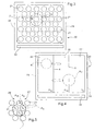
- the hob is thus shown schematically from above.
- this hob can be embedded or be an integral part of a worktop and possibly be associated with other cooking devices, such as an oven or other cooking stoves arranged in the same plane.
- the hob comprises a plurality of heating elements arranged in the hob, and for example several small induction heating elements arranged in the cooking hob.
- the heating elements 21 are thus distributed along a two-dimensional grid in the cooking plane of the table 20.
- This hob thus has a large cooking zone, up to the size of the hob and for heating one or more containers without predetermined location of the cooking chamber.
- the user has full latitude to position the cooking vessel at any point on the hob.
- Each heating element 21 consists of a small winding or elementary inductor.
- these heating elements 21 are of circular shape and staggered in the cooking plane, so as to cover the entire surface of the hob.
- the size of the inductors 21 is small enough that any container size covers at least one elementary inductor.
- each elementary inductor 21 may be equal to 70 or 80 mm.
- Each inductor is independently powered and has independent heating power control means.
- the maximum power supplied by each inductor is of the order of 700 W. It is thus possible to obtain a total power of approximately 2800 W for a medium-sized container, approximately 18 cm in diameter. , which would recover four inductors 21.
- the traditional control system of such a hob can manage one or more containers placed on the hob and apply different powers, depending on the desired power demanded by the user, for each container.
- the hob 20 comprises a control and display keyboard 22.
- Each heating element 21 is associated with means for detecting the presence of a container placed on the cooking surface in line with this heating element 21.
- the elementary inductors 21 constitute both the heating means of the container and means for detecting the presence of a container.
- the detection means are adapted detecting a cooking vessel disposed in line with a subset of heating elements constituting a cooking zone.
- the position of the container on the cooking surface can be determined and a cooking zone consisting of one or more adjacent inductors can thus be defined.
- the hob 20 comprises, as previously, centralized control means which make it possible to control the operation of the power control means of each inductor so that the heating power associated with a zone detected cooking is equal to a predefined value.
- the predefined value of the heating power associated with each cooking zone may depend, for example, on the relative position of this cooking zone with respect to two edges of the hob.
- the heating power of predefined value may depend on the position of the container relative to the distance between the left side edges 23 and right 24 of the hob.
- the centralized control means are then adapted to analyze the responses provided by the means for detecting the presence of a container.
- the value of the rms current measured at each inductor 21 allows the centralized control means to determine the inductor (s) covered at least partially by a container.
- This set of elementary inductors 21 thus constitutes a cooking zone.
- an elementary inductor 21 belongs to a cooking zone when its recovery rate is greater than a threshold value, for example 10%.
- the centralized control means are further adapted to determine the heating power to be associated with this cooking zone Z.
- the associated heating power corresponds to a maximum heating power.
- the predefined value of the heating power will be of the order of 2800-3000 W.
- the predefined value of the heating power associated with this cooking zone Z may be equal to the minimum value of the cooking table Z. cooking, of the order of 100 W.
- Any intermediate position of the detected heating zone Z gives rise to a calculation of a predefined value of heating power depending on the relative position of the container with respect to these two lateral edges 23, 24.
- the predefined value of the heating power associated with this cooking zone Z is equal to 50% of the maximum value. the power delivered by the covered inductors.
- a predefined heating power will be associated with this container.
- This embodiment makes it possible to cover the range of heating power available between a minimum power and a maximum power, simply by moving the cooking vessel.
- the relative position of the cooking zone could also be determined relative to the center and an edge of the hob.
- the heating power has a maximum predefined value.
- the newly detected cooking zones Z are associated with a heating power with a lower preset value.
- the user can change the heating power delivered to the container by simply moving the container on the hob.
- the centralized control means detect, by means of the value of the rms current measured at each elementary inductor 21, the displacement of this vessel and the new cooking zone Z displaced.
- the heating power is changed to be equal to the preset value, stored or calculated by the centralized control means.
- the hob is partitioned into several portions, each portion of the hob being associated with a predefined value of heating power.
- the hob is thus pre-cut fictitiously into several portions respectively associated with predefined values of heating power. Depending on the membership of a cooking zone to one or other of these portions of the hob, a predefined heating power value is associated with the cooking zone.
- the heating power associated with this cooking zone is equal to the preset value of the heating power associated with the portion of the cooking zone. cooking plan.
- the hob is cut into three portions 25, 26, 27.
- Each portion 25, 26, 27 is associated with a predefined value of heating power P 12 , P 10 and P 6 , respectively equal for example to 3000, 1500 and 500 W, for a medium-sized container covering approximately four elementary inductors 21 .
- the preset heating power values P 12 , P 10 and P 6 are stored by default in the centralized control means.
- the portions of the hob are substantially rectangular and arranged successively from one edge to the other of the hob.
- the portions of the hob could be arranged from the center to the edges of the hob, the heating power associated with the central portion in the form of a circle being greater than the outer portion adjacent to the edges of the hob .
- the hob would thus be shared for example in a disk-shaped central zone, an intermediate zone annular, and an outer zone extending between the annular intermediate zone and the edges of the hob.
- the hob 20 could also include adjustment means at the control panel 22, accessible to the user and allowing him to set beforehand the preset value of the heating power associated with each portion 25, 26 , 27 of the hob.
- each portion 25, 26, 27 corresponds to a certain number of inductors, each elementary inductor 21 belonging in its entirety to one or other of these portions 25, 26, 27.
- the control means in operation of the elementary inductors covered 21 are implemented to control in operation this cooking zone according to the heating power with preset value P 12 .
- the predefined heating power P 12 is distributed over the different elementary inductors 21 belonging to the cooking zone, as a function of the recovery rate of each inductor by the receptacle.
- the user can modify the heating power delivered to the container R 1 by moving it on the hob, and in this example, it can reduce the heating power from a maximum value to a minimum value by moving the container from the left to the right of the hob 20.
- an intermediate heating power associated with the container R 2 corresponds to an average of the predefined values of the heating powers associated with each portion 26, 27 partially covered by the container.
- the average of the powers can thus be weighted according to the recovery rate of each elementary inductor 21 belonging to the detected cooking zone.
- the average takes into account the number of inductors covered by the container R 2 and the recovery rate of each of these inductors 21.
- the user can, by moving the container on the hob, change the heating power associated with this container between the P 12 to P 6 values of available power.
- the heating element (s) of the hob constituting each hearth or cooking zone could also be radiant elements, electric heating resistors or gas burners, since a device for detecting the presence of a container can be implemented in parallel in the hob, for example by means of a matrix array of inductors for detecting the presence of a load placed on the hob.
Landscapes
- Physics & Mathematics (AREA)
- Electromagnetism (AREA)
- Chemical & Material Sciences (AREA)
- Engineering & Computer Science (AREA)
- Ceramic Engineering (AREA)
- Electric Stoves And Ranges (AREA)
- Induction Heating Cooking Devices (AREA)
- Control Of Resistance Heating (AREA)
Applications Claiming Priority (2)
| Application Number | Priority Date | Filing Date | Title |
|---|---|---|---|
| FR0406981A FR2872258B1 (fr) | 2004-06-25 | 2004-06-25 | Table de cuisson a plusieurs zones de cuisson |
| EP05291358A EP1610590B1 (de) | 2004-06-25 | 2005-06-24 | Kochmuldeneinheit mit mehreren Kochstellen |
Related Parent Applications (2)
| Application Number | Title | Priority Date | Filing Date |
|---|---|---|---|
| EP05291358A Division EP1610590B1 (de) | 2004-06-25 | 2005-06-24 | Kochmuldeneinheit mit mehreren Kochstellen |
| EP05291358.9 Division | 2005-06-24 |
Publications (3)
| Publication Number | Publication Date |
|---|---|
| EP2265087A2 true EP2265087A2 (de) | 2010-12-22 |
| EP2265087A3 EP2265087A3 (de) | 2011-01-12 |
| EP2265087B1 EP2265087B1 (de) | 2017-03-15 |
Family
ID=34945663
Family Applications (2)
| Application Number | Title | Priority Date | Filing Date |
|---|---|---|---|
| EP05291358A Expired - Lifetime EP1610590B1 (de) | 2004-06-25 | 2005-06-24 | Kochmuldeneinheit mit mehreren Kochstellen |
| EP10012104.5A Expired - Lifetime EP2265087B1 (de) | 2004-06-25 | 2005-06-24 | Kochherd mit mehreren unabhängigen Kochplatten |
Family Applications Before (1)
| Application Number | Title | Priority Date | Filing Date |
|---|---|---|---|
| EP05291358A Expired - Lifetime EP1610590B1 (de) | 2004-06-25 | 2005-06-24 | Kochmuldeneinheit mit mehreren Kochstellen |
Country Status (4)
| Country | Link |
|---|---|
| EP (2) | EP1610590B1 (de) |
| ES (2) | ES2386356T3 (de) |
| FR (1) | FR2872258B1 (de) |
| PL (1) | PL1610590T3 (de) |
Cited By (2)
| Publication number | Priority date | Publication date | Assignee | Title |
|---|---|---|---|---|
| EP2800453B1 (de) | 2013-04-30 | 2018-09-19 | Electrolux Appliances Aktiebolag | Kochfeld und Verfahren zum Betreiben solch eines Kochfelds |
| EP3028535B1 (de) | 2013-07-31 | 2019-09-11 | BSH Hausgeräte GmbH | Kochfeldvorrichtung |
Families Citing this family (39)
| Publication number | Priority date | Publication date | Assignee | Title |
|---|---|---|---|---|
| ATE479315T1 (de) * | 2006-11-09 | 2010-09-15 | Menu System Ag | Verfahren zur steuerung eines induktionskochgeräts und induktionskochgerät |
| ES2310107B1 (es) * | 2006-11-21 | 2009-08-27 | Bsh Electrodomesticos España, S.A. | Dispositivo de calentamiento y procedimiento para el calentamiento de objetos. |
| ES2304892B1 (es) | 2007-04-09 | 2009-06-04 | Bsh Electrodomesticos España, S.A. | Campo de coccion y procedimiento para el accionamiento de un campo de coccion. |
| WO2009024899A2 (en) * | 2007-08-21 | 2009-02-26 | Koninklijke Philips Electronics N.V. | Induction heating appliance |
| ES2329326B1 (es) * | 2007-10-17 | 2010-08-30 | Bsh Electrodomesticos España, S.A. | Dispositivo de coccion y procedimiento con un dispositivo de coccion. |
| ES2331037B1 (es) * | 2007-10-25 | 2010-09-21 | Bsh Electrodomesticos España, S.A. | Campo de coccion y procedimiento para el accionamiento de un campo de coccion. |
| FR2936041B1 (fr) * | 2008-09-18 | 2012-12-28 | Fagorbrandt Sas | Procede de commande d'une table de cuisson |
| DE102009020905A1 (de) * | 2009-05-12 | 2010-12-09 | Diehl Ako Stiftung & Co. Kg | Kochfeld |
| DE102009022898A1 (de) * | 2009-05-27 | 2010-12-16 | Diehl Ako Stiftung & Co. Kg | Kochfeld |
| ITTO20090942A1 (it) | 2009-12-01 | 2011-06-02 | Indesit Co Spa | Piano cottura e metodo per il suo controllo |
| FR2960376B1 (fr) * | 2010-05-21 | 2012-06-08 | Fagorbrandt Sas | Procede de commande en fonctionnement d'un ensemble d'inducteurs d'une table a induction |
| FR2966005B1 (fr) * | 2010-10-07 | 2015-11-06 | Fagorbrandt Sas | Procede de commande en fonctionnement d'un ensemble d'inducteurs d'une table de cuisson a induction et table de cuisson a induction associee |
| FR2970837B1 (fr) * | 2011-01-26 | 2014-09-05 | Fagorbrandt Sas | Procede d'optimisation de positionnement d'au moins un recipient dispose au-dessus d'un ensemble d'inducteurs d'une table de cuisson a induction et table de cuisson a induction associee |
| EP2506662B1 (de) | 2011-04-02 | 2016-09-07 | Electrolux Home Products Corporation N.V. | Induktionskochfeld mit Topferkennungsvorrichtung und Verfahren zum Betreiben eines Induktionkochfelds |
| FR2984463B1 (fr) * | 2011-12-16 | 2017-12-22 | Fagorbrandt Sas | Table de cuisson comprenant au moins deux parties de cuisson d'un plan de cuisson |
| DE102012212350B4 (de) * | 2012-07-13 | 2019-02-07 | E.G.O. Elektro-Gerätebau GmbH | Kochfeld |
| EP2704523B2 (de) * | 2012-09-03 | 2019-12-18 | BSH Hausgeräte GmbH | Induktionskochfeldvorrichtung |
| EP2709424B1 (de) * | 2012-09-17 | 2015-09-02 | Electrolux Professional S.p.A. | Verbessertes Induktionskochfeld |
| US10605464B2 (en) | 2012-10-15 | 2020-03-31 | Whirlpool Corporation | Induction cooktop |
| ITTO20120896A1 (it) | 2012-10-15 | 2014-04-16 | Indesit Co Spa | Piano cottura a induzione |
| ES2655712T3 (es) * | 2013-07-31 | 2018-02-21 | BSH Hausgeräte GmbH | Dispositivo de campos de cocción |
| WO2015015362A1 (de) * | 2013-07-31 | 2015-02-05 | BSH Bosch und Siemens Hausgeräte GmbH | Kochfeldvorrichtung |
| ES2634872T3 (es) * | 2013-07-31 | 2017-09-29 | BSH Hausgeräte GmbH | Dispositivo de encimera de cocción |
| EP3028536B1 (de) | 2013-07-31 | 2020-04-22 | BSH Hausgeräte GmbH | Kochfeldvorrichtung |
| EP3024300B1 (de) | 2013-09-05 | 2017-08-30 | Electrolux Appliances Aktiebolag | Induktionskochfeld mit einer kochstelle mit drei oder mehr induktionsspulen und verfahren zur steuerung einer kochstelle |
| ES2535245B1 (es) * | 2013-11-05 | 2016-02-16 | Bsh Electrodomésticos España, S.A. | Dispositivo de campo de cocción por inducción |
| WO2016134779A1 (en) * | 2015-02-26 | 2016-09-01 | Arcelik Anonim Sirketi | Induction cooking appliance with improved cooking performance |
| DE102016217783A1 (de) | 2016-09-16 | 2018-03-22 | E.G.O. Elektro-Gerätebau GmbH | Verfahren zum Betrieb eines Kochfeldes mit mehreren Heizeinrichtungen |
| FR3068117B1 (fr) * | 2017-06-27 | 2019-11-01 | Frima International Ag | Systeme modulaire comprenant au moins deux types d'appareils de cuisson et appareil de cuisson |
| EP3432682B1 (de) | 2017-07-18 | 2026-04-08 | Whirlpool Corporation | Verfahren zum betreiben eines induktionskochfelds und kochfeld mit diesem verfahren |
| US10993292B2 (en) | 2017-10-23 | 2021-04-27 | Whirlpool Corporation | System and method for tuning an induction circuit |
| ES2719504A1 (es) * | 2018-01-08 | 2019-07-10 | Bsh Electrodomesticos Espana Sa | Procedimiento para activar un campo de cocción, campo de cocción fabricado para utilizar este procedimiento |
| ES2719130A1 (es) * | 2018-01-08 | 2019-07-08 | Bsh Electrodomesticos Espana Sa | Dispositivo de campo de coccion |
| ES2719650A1 (es) * | 2018-01-08 | 2019-07-11 | Bsh Electrodomesticos Espana Sa | Dispositivo de campo de coccion |
| US12302478B2 (en) | 2018-04-23 | 2025-05-13 | Whirlpool Corporation | Control circuits and methods for distributed induction heating devices |
| US11140751B2 (en) | 2018-04-23 | 2021-10-05 | Whirlpool Corporation | System and method for controlling quasi-resonant induction heating devices |
| US12588112B2 (en) | 2018-04-23 | 2026-03-24 | Whirlpool Corporation | System and method for controlling induction heating devices with series connected switching devices |
| CN112393283B (zh) * | 2019-08-12 | 2023-04-07 | 佛山市顺德区美的电热电器制造有限公司 | 烹饪器具 |
| DE102020209648A1 (de) | 2020-07-30 | 2022-02-03 | E.G.O. Elektro-Gerätebau GmbH | Verfahren zum Betrieb eines Kochfelds und Kochfeld |
Citations (2)
| Publication number | Priority date | Publication date | Assignee | Title |
|---|---|---|---|---|
| DE4007680A1 (de) | 1990-03-10 | 1991-09-19 | Grass Ag | Heizplatte |
| FR2728132A1 (fr) | 1994-12-09 | 1996-06-14 | Bonnet Sa | Dispositif de chauffage par induction de recipient et procede de commande d'un tel dispositif |
Family Cites Families (2)
| Publication number | Priority date | Publication date | Assignee | Title |
|---|---|---|---|---|
| DE3002623A1 (de) * | 1980-01-25 | 1981-07-30 | Neff - Werke Carl Neff GmbH, 7518 Bretten | Einbau-kochfeld |
| FR2792158B1 (fr) * | 1999-04-09 | 2001-05-18 | Jaeger Regulation | Foyer de cuisson par induction modulable a rayonnement reduit et procede de realisation |
-
2004
- 2004-06-25 FR FR0406981A patent/FR2872258B1/fr not_active Expired - Fee Related
-
2005
- 2005-06-24 ES ES05291358T patent/ES2386356T3/es not_active Expired - Lifetime
- 2005-06-24 ES ES10012104.5T patent/ES2628230T3/es not_active Expired - Lifetime
- 2005-06-24 EP EP05291358A patent/EP1610590B1/de not_active Expired - Lifetime
- 2005-06-24 PL PL05291358T patent/PL1610590T3/pl unknown
- 2005-06-24 EP EP10012104.5A patent/EP2265087B1/de not_active Expired - Lifetime
Patent Citations (2)
| Publication number | Priority date | Publication date | Assignee | Title |
|---|---|---|---|---|
| DE4007680A1 (de) | 1990-03-10 | 1991-09-19 | Grass Ag | Heizplatte |
| FR2728132A1 (fr) | 1994-12-09 | 1996-06-14 | Bonnet Sa | Dispositif de chauffage par induction de recipient et procede de commande d'un tel dispositif |
Cited By (4)
| Publication number | Priority date | Publication date | Assignee | Title |
|---|---|---|---|---|
| EP2800453B1 (de) | 2013-04-30 | 2018-09-19 | Electrolux Appliances Aktiebolag | Kochfeld und Verfahren zum Betreiben solch eines Kochfelds |
| EP3448118B1 (de) | 2013-04-30 | 2020-07-15 | Electrolux Appliances Aktiebolag | Kochfeld und verfahren zum betreiben solch eines kochfelds |
| EP3028535B1 (de) | 2013-07-31 | 2019-09-11 | BSH Hausgeräte GmbH | Kochfeldvorrichtung |
| EP3028535B2 (de) † | 2013-07-31 | 2022-09-21 | BSH Hausgeräte GmbH | Kochfeldvorrichtung |
Also Published As
| Publication number | Publication date |
|---|---|
| EP1610590B1 (de) | 2012-06-06 |
| ES2628230T3 (es) | 2017-08-02 |
| EP2265087B1 (de) | 2017-03-15 |
| ES2386356T3 (es) | 2012-08-17 |
| FR2872258A1 (fr) | 2005-12-30 |
| EP2265087A3 (de) | 2011-01-12 |
| EP1610590A1 (de) | 2005-12-28 |
| FR2872258B1 (fr) | 2006-11-10 |
| PL1610590T3 (pl) | 2012-11-30 |
Similar Documents
| Publication | Publication Date | Title |
|---|---|---|
| EP2265087B1 (de) | Kochherd mit mehreren unabhängigen Kochplatten | |
| EP2551600B1 (de) | Kochfeld und Verfahren zur Steuerung, wenn das Kochfeld in Betrieb ist | |
| EP2166290B1 (de) | Method for controlling a hob | |
| US20210196078A1 (en) | Grill device, components of grill device, and related methods | |
| FR2984463A1 (fr) | Table de cuisson comprenant au moins deux parties de cuisson d'un plan de cuisson | |
| EP2482613B1 (de) | Verfahren zur Optimierung der Positionierung mindestens eines Behälters auf einer Gruppe von Induktoren eines Induktionskochfeldes, und zugehöriges Induktionskochfeld | |
| WO2020169111A1 (en) | Control system for cooking device | |
| EP2440007B1 (de) | Steuerverfahren bei Betrieb einer Reihe von Induktoren eines Induktionskochfeldes, und zugehöriges Induktionskochfeld | |
| KR20140069536A (ko) | 가스레인지의 노브 위치 자동 판단장치 및 이를 이용한 과열방지 제어방법 | |
| EP2440011A2 (de) | Steuerverfahren bei Betrieb einer Reihe von Induktoren eines Induktionskochfeldes, und zugehöriges Induktionskochfeld | |
| EP2440012B1 (de) | Steuerverfahren bei Betrieb einer Reihe von Induktoren eines Induktionskochfeldes, und zugehöriges Induktionskochfeld | |
| EP2440008B1 (de) | Steuerverfahren bei Betrieb einer Reihe von Induktoren eines Induktionskochfeldes, und zugehöriges Induktionskochfeld | |
| EP2144480B1 (de) | Verfahren zur Ansteuerung von zumindest einem Heizelement eines Gargeräts | |
| EP1675435B2 (de) | Steuerungsverfahren eines Kochfeldes und sein Kochfeld | |
| EP3065505B1 (de) | Verfahren zur steuerung eines kochgeräts und entsprechendes kochgerät | |
| EP2341407B1 (de) | Vorrichtung zur Steuerung eines Haushaltsgeräts mit berührungsempfindlichen Tasten | |
| US20260114668A1 (en) | Electric Grill with Enhanced Conductive Heating | |
| FR2910599A1 (fr) | Procede de verrouillage de moyens de commande des foyers d'une table de cuisson | |
| JP2022066433A (ja) | 誘導加熱調理器 | |
| FR2686148A1 (fr) | Dispositif de visualisation de l'intensite de la flamme d'un foyer a gaz. | |
| FR2978531A1 (fr) | Dispositif de commande d'un appareil electromenager comprenant une bande de commande sensitive formee par une pluralite de capteurs avec touche sensitive | |
| FR2899784A1 (fr) | Appareil a griller ou rotir, a chauffage par induction |
Legal Events
| Date | Code | Title | Description |
|---|---|---|---|
| PUAI | Public reference made under article 153(3) epc to a published international application that has entered the european phase |
Free format text: ORIGINAL CODE: 0009012 |
|
| PUAL | Search report despatched |
Free format text: ORIGINAL CODE: 0009013 |
|
| AC | Divisional application: reference to earlier application |
Ref document number: 1610590 Country of ref document: EP Kind code of ref document: P |
|
| AK | Designated contracting states |
Kind code of ref document: A2 Designated state(s): AT BE BG CH CY CZ DE DK EE ES FI FR GB GR HU IE IS IT LI LT LU MC NL PL PT RO SE SI SK TR |
|
| AK | Designated contracting states |
Kind code of ref document: A3 Designated state(s): AT BE BG CH CY CZ DE DK EE ES FI FR GB GR HU IE IS IT LI LT LU MC NL PL PT RO SE SI SK TR |
|
| 17P | Request for examination filed |
Effective date: 20110712 |
|
| 17Q | First examination report despatched |
Effective date: 20120207 |
|
| 19U | Interruption of proceedings before grant |
Effective date: 20140411 |
|
| 19W | Proceedings resumed before grant after interruption of proceedings |
Effective date: 20150701 |
|
| RAP1 | Party data changed (applicant data changed or rights of an application transferred) |
Owner name: GROUPE BRANDT |
|
| GRAP | Despatch of communication of intention to grant a patent |
Free format text: ORIGINAL CODE: EPIDOSNIGR1 |
|
| INTG | Intention to grant announced |
Effective date: 20161014 |
|
| STAA | Information on the status of an ep patent application or granted ep patent |
Free format text: STATUS: GRANT OF PATENT IS INTENDED |
|
| GRAS | Grant fee paid |
Free format text: ORIGINAL CODE: EPIDOSNIGR3 |
|
| GRAA | (expected) grant |
Free format text: ORIGINAL CODE: 0009210 |
|
| STAA | Information on the status of an ep patent application or granted ep patent |
Free format text: STATUS: THE PATENT HAS BEEN GRANTED |
|
| AC | Divisional application: reference to earlier application |
Ref document number: 1610590 Country of ref document: EP Kind code of ref document: P |
|
| AK | Designated contracting states |
Kind code of ref document: B1 Designated state(s): AT BE BG CH CY CZ DE DK EE ES FI FR GB GR HU IE IS IT LI LT LU MC NL PL PT RO SE SI SK TR |
|
| REG | Reference to a national code |
Ref country code: CH Ref legal event code: EP Ref country code: GB Ref legal event code: FG4D Free format text: NOT ENGLISH |
|
| REG | Reference to a national code |
Ref country code: IE Ref legal event code: FG4D Free format text: LANGUAGE OF EP DOCUMENT: FRENCH |
|
| REG | Reference to a national code |
Ref country code: AT Ref legal event code: REF Ref document number: 876732 Country of ref document: AT Kind code of ref document: T Effective date: 20170415 |
|
| REG | Reference to a national code |
Ref country code: DE Ref legal event code: R096 Ref document number: 602005051542 Country of ref document: DE |
|
| REG | Reference to a national code |
Ref country code: FR Ref legal event code: PLFP Year of fee payment: 13 |
|
| REG | Reference to a national code |
Ref country code: NL Ref legal event code: MP Effective date: 20170315 |
|
| REG | Reference to a national code |
Ref country code: LT Ref legal event code: MG4D |
|
| PG25 | Lapsed in a contracting state [announced via postgrant information from national office to epo] |
Ref country code: LT Free format text: LAPSE BECAUSE OF FAILURE TO SUBMIT A TRANSLATION OF THE DESCRIPTION OR TO PAY THE FEE WITHIN THE PRESCRIBED TIME-LIMIT Effective date: 20170315 Ref country code: FI Free format text: LAPSE BECAUSE OF FAILURE TO SUBMIT A TRANSLATION OF THE DESCRIPTION OR TO PAY THE FEE WITHIN THE PRESCRIBED TIME-LIMIT Effective date: 20170315 Ref country code: GR Free format text: LAPSE BECAUSE OF FAILURE TO SUBMIT A TRANSLATION OF THE DESCRIPTION OR TO PAY THE FEE WITHIN THE PRESCRIBED TIME-LIMIT Effective date: 20170616 |
|
| REG | Reference to a national code |
Ref country code: ES Ref legal event code: FG2A Ref document number: 2628230 Country of ref document: ES Kind code of ref document: T3 Effective date: 20170802 |
|
| REG | Reference to a national code |
Ref country code: AT Ref legal event code: MK05 Ref document number: 876732 Country of ref document: AT Kind code of ref document: T Effective date: 20170315 |
|
| PG25 | Lapsed in a contracting state [announced via postgrant information from national office to epo] |
Ref country code: SE Free format text: LAPSE BECAUSE OF FAILURE TO SUBMIT A TRANSLATION OF THE DESCRIPTION OR TO PAY THE FEE WITHIN THE PRESCRIBED TIME-LIMIT Effective date: 20170315 Ref country code: BG Free format text: LAPSE BECAUSE OF FAILURE TO SUBMIT A TRANSLATION OF THE DESCRIPTION OR TO PAY THE FEE WITHIN THE PRESCRIBED TIME-LIMIT Effective date: 20170615 |
|
| PG25 | Lapsed in a contracting state [announced via postgrant information from national office to epo] |
Ref country code: NL Free format text: LAPSE BECAUSE OF FAILURE TO SUBMIT A TRANSLATION OF THE DESCRIPTION OR TO PAY THE FEE WITHIN THE PRESCRIBED TIME-LIMIT Effective date: 20170315 |
|
| PG25 | Lapsed in a contracting state [announced via postgrant information from national office to epo] |
Ref country code: RO Free format text: LAPSE BECAUSE OF FAILURE TO SUBMIT A TRANSLATION OF THE DESCRIPTION OR TO PAY THE FEE WITHIN THE PRESCRIBED TIME-LIMIT Effective date: 20170315 Ref country code: AT Free format text: LAPSE BECAUSE OF FAILURE TO SUBMIT A TRANSLATION OF THE DESCRIPTION OR TO PAY THE FEE WITHIN THE PRESCRIBED TIME-LIMIT Effective date: 20170315 Ref country code: EE Free format text: LAPSE BECAUSE OF FAILURE TO SUBMIT A TRANSLATION OF THE DESCRIPTION OR TO PAY THE FEE WITHIN THE PRESCRIBED TIME-LIMIT Effective date: 20170315 Ref country code: SK Free format text: LAPSE BECAUSE OF FAILURE TO SUBMIT A TRANSLATION OF THE DESCRIPTION OR TO PAY THE FEE WITHIN THE PRESCRIBED TIME-LIMIT Effective date: 20170315 Ref country code: CZ Free format text: LAPSE BECAUSE OF FAILURE TO SUBMIT A TRANSLATION OF THE DESCRIPTION OR TO PAY THE FEE WITHIN THE PRESCRIBED TIME-LIMIT Effective date: 20170315 |
|
| PG25 | Lapsed in a contracting state [announced via postgrant information from national office to epo] |
Ref country code: PL Free format text: LAPSE BECAUSE OF FAILURE TO SUBMIT A TRANSLATION OF THE DESCRIPTION OR TO PAY THE FEE WITHIN THE PRESCRIBED TIME-LIMIT Effective date: 20170315 Ref country code: IS Free format text: LAPSE BECAUSE OF FAILURE TO SUBMIT A TRANSLATION OF THE DESCRIPTION OR TO PAY THE FEE WITHIN THE PRESCRIBED TIME-LIMIT Effective date: 20170715 Ref country code: PT Free format text: LAPSE BECAUSE OF FAILURE TO SUBMIT A TRANSLATION OF THE DESCRIPTION OR TO PAY THE FEE WITHIN THE PRESCRIBED TIME-LIMIT Effective date: 20170717 |
|
| REG | Reference to a national code |
Ref country code: DE Ref legal event code: R097 Ref document number: 602005051542 Country of ref document: DE |
|
| PLBE | No opposition filed within time limit |
Free format text: ORIGINAL CODE: 0009261 |
|
| STAA | Information on the status of an ep patent application or granted ep patent |
Free format text: STATUS: NO OPPOSITION FILED WITHIN TIME LIMIT |
|
| PG25 | Lapsed in a contracting state [announced via postgrant information from national office to epo] |
Ref country code: DK Free format text: LAPSE BECAUSE OF FAILURE TO SUBMIT A TRANSLATION OF THE DESCRIPTION OR TO PAY THE FEE WITHIN THE PRESCRIBED TIME-LIMIT Effective date: 20170315 Ref country code: MC Free format text: LAPSE BECAUSE OF FAILURE TO SUBMIT A TRANSLATION OF THE DESCRIPTION OR TO PAY THE FEE WITHIN THE PRESCRIBED TIME-LIMIT Effective date: 20170315 |
|
| REG | Reference to a national code |
Ref country code: CH Ref legal event code: PL |
|
| 26N | No opposition filed |
Effective date: 20171218 |
|
| PG25 | Lapsed in a contracting state [announced via postgrant information from national office to epo] |
Ref country code: SI Free format text: LAPSE BECAUSE OF FAILURE TO SUBMIT A TRANSLATION OF THE DESCRIPTION OR TO PAY THE FEE WITHIN THE PRESCRIBED TIME-LIMIT Effective date: 20170315 |
|
| REG | Reference to a national code |
Ref country code: IE Ref legal event code: MM4A |
|
| PG25 | Lapsed in a contracting state [announced via postgrant information from national office to epo] |
Ref country code: CH Free format text: LAPSE BECAUSE OF NON-PAYMENT OF DUE FEES Effective date: 20170630 Ref country code: IE Free format text: LAPSE BECAUSE OF NON-PAYMENT OF DUE FEES Effective date: 20170624 Ref country code: LI Free format text: LAPSE BECAUSE OF NON-PAYMENT OF DUE FEES Effective date: 20170630 Ref country code: LU Free format text: LAPSE BECAUSE OF NON-PAYMENT OF DUE FEES Effective date: 20170624 |
|
| REG | Reference to a national code |
Ref country code: FR Ref legal event code: PLFP Year of fee payment: 14 |
|
| REG | Reference to a national code |
Ref country code: BE Ref legal event code: MM Effective date: 20170630 |
|
| PG25 | Lapsed in a contracting state [announced via postgrant information from national office to epo] |
Ref country code: BE Free format text: LAPSE BECAUSE OF NON-PAYMENT OF DUE FEES Effective date: 20170630 |
|
| PG25 | Lapsed in a contracting state [announced via postgrant information from national office to epo] |
Ref country code: HU Free format text: LAPSE BECAUSE OF FAILURE TO SUBMIT A TRANSLATION OF THE DESCRIPTION OR TO PAY THE FEE WITHIN THE PRESCRIBED TIME-LIMIT; INVALID AB INITIO Effective date: 20050624 |
|
| PG25 | Lapsed in a contracting state [announced via postgrant information from national office to epo] |
Ref country code: CY Free format text: LAPSE BECAUSE OF NON-PAYMENT OF DUE FEES Effective date: 20170315 |
|
| PGFP | Annual fee paid to national office [announced via postgrant information from national office to epo] |
Ref country code: GB Payment date: 20190620 Year of fee payment: 15 |
|
| PG25 | Lapsed in a contracting state [announced via postgrant information from national office to epo] |
Ref country code: TR Free format text: LAPSE BECAUSE OF FAILURE TO SUBMIT A TRANSLATION OF THE DESCRIPTION OR TO PAY THE FEE WITHIN THE PRESCRIBED TIME-LIMIT Effective date: 20170315 |
|
| GBPC | Gb: european patent ceased through non-payment of renewal fee |
Effective date: 20200624 |
|
| PG25 | Lapsed in a contracting state [announced via postgrant information from national office to epo] |
Ref country code: GB Free format text: LAPSE BECAUSE OF NON-PAYMENT OF DUE FEES Effective date: 20200624 |
|
| PGFP | Annual fee paid to national office [announced via postgrant information from national office to epo] |
Ref country code: IT Payment date: 20220630 Year of fee payment: 18 Ref country code: ES Payment date: 20220711 Year of fee payment: 18 Ref country code: DE Payment date: 20220714 Year of fee payment: 18 |
|
| PGFP | Annual fee paid to national office [announced via postgrant information from national office to epo] |
Ref country code: FR Payment date: 20230628 Year of fee payment: 19 |
|
| REG | Reference to a national code |
Ref country code: DE Ref legal event code: R119 Ref document number: 602005051542 Country of ref document: DE |
|
| PG25 | Lapsed in a contracting state [announced via postgrant information from national office to epo] |
Ref country code: DE Free format text: LAPSE BECAUSE OF NON-PAYMENT OF DUE FEES Effective date: 20240103 |
|
| PG25 | Lapsed in a contracting state [announced via postgrant information from national office to epo] |
Ref country code: IT Free format text: LAPSE BECAUSE OF NON-PAYMENT OF DUE FEES Effective date: 20230624 |
|
| REG | Reference to a national code |
Ref country code: ES Ref legal event code: FD2A Effective date: 20240801 |
|
| PG25 | Lapsed in a contracting state [announced via postgrant information from national office to epo] |
Ref country code: ES Free format text: LAPSE BECAUSE OF NON-PAYMENT OF DUE FEES Effective date: 20230625 |
|
| PG25 | Lapsed in a contracting state [announced via postgrant information from national office to epo] |
Ref country code: ES Free format text: LAPSE BECAUSE OF NON-PAYMENT OF DUE FEES Effective date: 20230625 |
|
| PG25 | Lapsed in a contracting state [announced via postgrant information from national office to epo] |
Ref country code: FR Free format text: LAPSE BECAUSE OF NON-PAYMENT OF DUE FEES Effective date: 20240630 |