EP2264321B1 - Propellerlüfter aus kunststoff - Google Patents
Propellerlüfter aus kunststoff Download PDFInfo
- Publication number
- EP2264321B1 EP2264321B1 EP09733424.7A EP09733424A EP2264321B1 EP 2264321 B1 EP2264321 B1 EP 2264321B1 EP 09733424 A EP09733424 A EP 09733424A EP 2264321 B1 EP2264321 B1 EP 2264321B1
- Authority
- EP
- European Patent Office
- Prior art keywords
- ring member
- blades
- propeller fan
- cylindrical ring
- circumferential surface
- Prior art date
- Legal status (The legal status is an assumption and is not a legal conclusion. Google has not performed a legal analysis and makes no representation as to the accuracy of the status listed.)
- Not-in-force
Links
- 239000004033 plastic Substances 0.000 title claims description 9
- 230000002093 peripheral effect Effects 0.000 claims description 13
- 238000000465 moulding Methods 0.000 claims description 7
- 239000002184 metal Substances 0.000 claims description 4
- 238000004519 manufacturing process Methods 0.000 claims description 2
- 238000007664 blowing Methods 0.000 description 13
- 230000001965 increasing effect Effects 0.000 description 13
- 230000000694 effects Effects 0.000 description 12
- 230000003014 reinforcing effect Effects 0.000 description 12
- 238000001746 injection moulding Methods 0.000 description 6
- 238000001816 cooling Methods 0.000 description 4
- 230000000670 limiting effect Effects 0.000 description 4
- XLYOFNOQVPJJNP-UHFFFAOYSA-N water Substances O XLYOFNOQVPJJNP-UHFFFAOYSA-N 0.000 description 4
- 239000004743 Polypropylene Substances 0.000 description 2
- 230000002411 adverse Effects 0.000 description 2
- 238000004378 air conditioning Methods 0.000 description 2
- 230000000052 comparative effect Effects 0.000 description 2
- 230000003247 decreasing effect Effects 0.000 description 2
- 230000004048 modification Effects 0.000 description 2
- 238000012986 modification Methods 0.000 description 2
- 230000036961 partial effect Effects 0.000 description 2
- 239000000243 solution Substances 0.000 description 2
- 230000002708 enhancing effect Effects 0.000 description 1
- 239000003365 glass fiber Substances 0.000 description 1
- -1 polypropylene Polymers 0.000 description 1
- 229920001155 polypropylene Polymers 0.000 description 1
- 230000003449 preventive effect Effects 0.000 description 1
- 230000002829 reductive effect Effects 0.000 description 1
- 230000002787 reinforcement Effects 0.000 description 1
- 238000011144 upstream manufacturing Methods 0.000 description 1
Images



Classifications
-
- F—MECHANICAL ENGINEERING; LIGHTING; HEATING; WEAPONS; BLASTING
- F04—POSITIVE - DISPLACEMENT MACHINES FOR LIQUIDS; PUMPS FOR LIQUIDS OR ELASTIC FLUIDS
- F04D—NON-POSITIVE-DISPLACEMENT PUMPS
- F04D29/00—Details, component parts, or accessories
- F04D29/26—Rotors specially for elastic fluids
- F04D29/32—Rotors specially for elastic fluids for axial flow pumps
- F04D29/34—Blade mountings
-
- B—PERFORMING OPERATIONS; TRANSPORTING
- B29—WORKING OF PLASTICS; WORKING OF SUBSTANCES IN A PLASTIC STATE IN GENERAL
- B29C—SHAPING OR JOINING OF PLASTICS; SHAPING OF MATERIAL IN A PLASTIC STATE, NOT OTHERWISE PROVIDED FOR; AFTER-TREATMENT OF THE SHAPED PRODUCTS, e.g. REPAIRING
- B29C33/00—Moulds or cores; Details thereof or accessories therefor
- B29C33/44—Moulds or cores; Details thereof or accessories therefor with means for, or specially constructed to facilitate, the removal of articles, e.g. of undercut articles
-
- F—MECHANICAL ENGINEERING; LIGHTING; HEATING; WEAPONS; BLASTING
- F04—POSITIVE - DISPLACEMENT MACHINES FOR LIQUIDS; PUMPS FOR LIQUIDS OR ELASTIC FLUIDS
- F04D—NON-POSITIVE-DISPLACEMENT PUMPS
- F04D29/00—Details, component parts, or accessories
- F04D29/26—Rotors specially for elastic fluids
- F04D29/32—Rotors specially for elastic fluids for axial flow pumps
- F04D29/325—Rotors specially for elastic fluids for axial flow pumps for axial flow fans
- F04D29/326—Rotors specially for elastic fluids for axial flow pumps for axial flow fans comprising a rotating shroud
-
- F—MECHANICAL ENGINEERING; LIGHTING; HEATING; WEAPONS; BLASTING
- F04—POSITIVE - DISPLACEMENT MACHINES FOR LIQUIDS; PUMPS FOR LIQUIDS OR ELASTIC FLUIDS
- F04D—NON-POSITIVE-DISPLACEMENT PUMPS
- F04D29/00—Details, component parts, or accessories
- F04D29/26—Rotors specially for elastic fluids
- F04D29/32—Rotors specially for elastic fluids for axial flow pumps
- F04D29/325—Rotors specially for elastic fluids for axial flow pumps for axial flow fans
- F04D29/329—Details of the hub
-
- F—MECHANICAL ENGINEERING; LIGHTING; HEATING; WEAPONS; BLASTING
- F04—POSITIVE - DISPLACEMENT MACHINES FOR LIQUIDS; PUMPS FOR LIQUIDS OR ELASTIC FLUIDS
- F04D—NON-POSITIVE-DISPLACEMENT PUMPS
- F04D29/00—Details, component parts, or accessories
- F04D29/26—Rotors specially for elastic fluids
- F04D29/32—Rotors specially for elastic fluids for axial flow pumps
- F04D29/38—Blades
- F04D29/384—Blades characterised by form
-
- F—MECHANICAL ENGINEERING; LIGHTING; HEATING; WEAPONS; BLASTING
- F04—POSITIVE - DISPLACEMENT MACHINES FOR LIQUIDS; PUMPS FOR LIQUIDS OR ELASTIC FLUIDS
- F04D—NON-POSITIVE-DISPLACEMENT PUMPS
- F04D29/00—Details, component parts, or accessories
- F04D29/66—Combating cavitation, whirls, noise, vibration or the like; Balancing
- F04D29/661—Combating cavitation, whirls, noise, vibration or the like; Balancing especially adapted for elastic fluid pumps
- F04D29/668—Combating cavitation, whirls, noise, vibration or the like; Balancing especially adapted for elastic fluid pumps damping or preventing mechanical vibrations
-
- B—PERFORMING OPERATIONS; TRANSPORTING
- B29—WORKING OF PLASTICS; WORKING OF SUBSTANCES IN A PLASTIC STATE IN GENERAL
- B29C—SHAPING OR JOINING OF PLASTICS; SHAPING OF MATERIAL IN A PLASTIC STATE, NOT OTHERWISE PROVIDED FOR; AFTER-TREATMENT OF THE SHAPED PRODUCTS, e.g. REPAIRING
- B29C33/00—Moulds or cores; Details thereof or accessories therefor
- B29C33/005—Moulds or cores; Details thereof or accessories therefor characterised by the location of the parting line of the mould parts
-
- B—PERFORMING OPERATIONS; TRANSPORTING
- B29—WORKING OF PLASTICS; WORKING OF SUBSTANCES IN A PLASTIC STATE IN GENERAL
- B29L—INDEXING SCHEME ASSOCIATED WITH SUBCLASS B29C, RELATING TO PARTICULAR ARTICLES
- B29L2031/00—Other particular articles
- B29L2031/08—Blades for rotors, stators, fans, turbines or the like, e.g. screw propellers
-
- F—MECHANICAL ENGINEERING; LIGHTING; HEATING; WEAPONS; BLASTING
- F05—INDEXING SCHEMES RELATING TO ENGINES OR PUMPS IN VARIOUS SUBCLASSES OF CLASSES F01-F04
- F05D—INDEXING SCHEME FOR ASPECTS RELATING TO NON-POSITIVE-DISPLACEMENT MACHINES OR ENGINES, GAS-TURBINES OR JET-PROPULSION PLANTS
- F05D2300/00—Materials; Properties thereof
- F05D2300/40—Organic materials
- F05D2300/43—Synthetic polymers, e.g. plastics; Rubber
-
- F—MECHANICAL ENGINEERING; LIGHTING; HEATING; WEAPONS; BLASTING
- F05—INDEXING SCHEMES RELATING TO ENGINES OR PUMPS IN VARIOUS SUBCLASSES OF CLASSES F01-F04
- F05D—INDEXING SCHEME FOR ASPECTS RELATING TO NON-POSITIVE-DISPLACEMENT MACHINES OR ENGINES, GAS-TURBINES OR JET-PROPULSION PLANTS
- F05D2300/00—Materials; Properties thereof
- F05D2300/60—Properties or characteristics given to material by treatment or manufacturing
- F05D2300/603—Composites; e.g. fibre-reinforced
Definitions
- the present invention relates to a plastic propeller fan having a plurality of blades that are integrally molded in a radial pattern on the outer circumference of a cylindrical hub.
- Plastic propeller fans applied to cooling fans for automobile radiators and air-conditioning condensers are installed in narrow engine compartments and are required to be lightweight and are thus under the constraint that the size in the airflow direction (depth dimension) cannot be increased. Therefore, the depth dimensions of blades, a hub, a shroud, etc. that constitute a propeller fan are made as thin as possible. In addition, the gap sizes between them and the radiator, the condenser, or the like should be as small as possible.
- the present invention is made in consideration of such circumstances, and an object thereof is to provide a propeller fan that can prevent deformation while maintaining the basic performance, such as the air blowing performance, efficiency, and noise performance.
- a propeller fan in accordance with claim 1 is provided.
- the strength of the blades can be increased without increasing the wall thickness of the blades.
- the ring member is provided at a dimension position of 5 to 45 from the outer peripheral edge, excluding the outermost peripheries of the blades; therefore, the reinforcing ring member can be provided without limiting the shape of the outermost peripheries of the blades that provide the highest efficiency for the air blowing function of the propeller fan.
- the ring member is in the form of a cylinder having a fixed width in the axial direction, the reinforcing effect against deformation of the blades in the axial direction can be enhanced.
- the cylindrical shape of the ring member can provide an airflow rectifying effect and can reduce a centripetal flow generated at the outer circumference of the fan to thereby prevent a decrease in the effective radius of the fan. This can therefore improve the basic performance, such as the air blowing performance, efficiency, and noise performance.
- level differences that are formed on the ring member due to the draft angles when the cylindrical ring member is integrally molded by injection molding are eliminated at the air inflow end by adjusting the wall thickness of the ring member and the draft angle provided at the inner circumferential surface side thereof, and level differences corresponding to the amount of adjustment are concentrated at the inner circumferential surface side of the ring member at the air outflow end.
- This can therefore eliminate the level differences, which act as resistance against the airflow, from the ring member. Accordingly, the ring member does not exert an adverse influence on the fan performance etc., and the propeller fan with the cylindrical ring member can easily be manufactured by injection molding, as in the related art.
- the propeller fan of the present invention may be configured such that the draft angle at the inner circumferential surface side of the cylindrical ring member is set larger than the draft angle at the outer circumferential surface side of the cylindrical ring member.
- the draft angle at the inner circumferential surface side of the cylindrical ring member is set larger than the draft angle at the outer circumferential surface side of the cylindrical ring member. Therefore, even if thermal shrinkage occurs during injection molding, the molding die can easily be removed because the draft angle at the inner circumferential surface side located in the direction of thermal shrinkage is set to be large. Accordingly, the provision of the cylindrical ring member does not hinder manufacturing of the propeller fan, so that the propeller fan can be manufactured as in the related art.
- the propeller fan of the present invention may be configured such that, in one of the propeller fans described above, the ring member is provided at positions passing through the crests of serrations provided at the trailing edges of the blades.
- the ring member is provided at positions passing through the crests of serrations provided at the trailing edges of the blades, the length of the ring member in a cord longitudinal direction on the blades can be maximized. This can therefore maximize the reinforcing effect of the ring member and can avoid stress concentration at the troughs due to provision of the ring member at the troughs of the serrations.
- the propeller fan of the present invention may be configured such that, in one of the propeller fans described above, in addition to the ring member provided at the dimension position, a ring member is provided concentrically at least one location on the inner circumference side thereof.
- a ring member is provided concentrically at at least one location on the inner circumference side thereof. This can therefore further enhance effects such as the reinforcing effect against deformation of the blades in the axial direction, the airflow rectifying effect, and reduction in the effective radius of the fan.
- the strength of the blades can be increased without increasing the wall thickness of the blades, and the reinforcing ring member can be provided without limiting the shape of the outermost peripheries of the blades that provide the highest efficiency for the air blowing function of the propeller fan.
- This can ensure flexibility in designing the shape of the outermost peripheries of the blades and can also maintain the basic performance of the propeller fan, such as the air blowing performance, efficiency, and noise performance, and the effect of preventing deformation by increasing the strength of the blades.
- Fig. 1 shows a perspective view of a propeller fan 1 according to the first embodiment of the present invention
- Fig. 2 shows a front view thereof
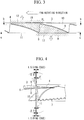
- Fig. 3 shows a partial side view as seen from the outer circumference.
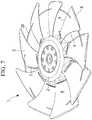
- the propeller fan 1 is an injection-molded component made of, for example, polypropylene plastic (PP) containing about 30 wt% of glass fibers and is configured such that a cylindrical hub 2 is provided at the center portion and a plurality of (nine in the illustrated example) blades (vanes) 3 are integrally formed in a radial pattern on the outer circumference of the hub 2.
- PP polypropylene plastic
- Each blade 3 has a leading edge 4 located upstream in the rotating direction in the circumferential direction, a trailing edge 5 located downstream in the rotating direction, and an outer peripheral edge 6 that joins the leading edge 4 and the trailing edge 5 together at the outermost peripheral position in the radial direction and has an airfoil shape in cross-section and a sickle shape in which the leading edge 4 is curved in the rotating direction, that is, toward the trailing edge 5 of the adjacent blade 3, so as to assume a convex shape, and the trailing edge 5 is slightly curved so as to assume a convex shape in a direction away from the leading edge 4 of the adjacent blade 3.
- the trailing edge 5 is provided with a serration 7.
- the blades 3 are integrally formed on the outer circumference of the cylindrical hub 2 with a predetermined inclination and are configured to have a fixed blade height (about 30 mm in this embodiment) in the axial direction between the leading edge 4 and the trailing edge 5.
- a fixed blade height about 30 mm in this embodiment
- the rear side of the plane of each drawing is assumed to be a positive pressure surface (pressure surface) 8
- the front side of the plane of each drawing is assumed to be a negative pressure surface 9, and air is circulated from the front side of the plane of the drawing toward the rear side.
- the above-descried propeller fan 1 is provided with a reinforcing ring member 10 that joins the plurality of blades 3 together.
- the reinforcing ring member 10 is constituted of a cylindrical thin-plate ring having a fixed width (substantially equal to or a little larger than the height of the blades) in the axial direction and is integrally molded with the blades 3.
- the reinforcing ring member 10 is provided at a dimension position of 5 to 45 from the outer peripheral edge 6, as shown in Fig. 2 .
- the position at which the ring member 10 is provided is determined in order to exclude the outermost peripheries of the blades 3 so as not to limit the shape of the outermost peripheries of the blades that provide the highest efficiency for the propeller fan 1 and to ensure a sufficient reinforcing effect against deformation of the blades 3, and is set, assuming that the radial size of the blades 3 is 100, at a dimension position of 5 to 45 from the outer peripheral edge 6, as described above.
- the propeller fan 1 provided with the ring member 10 is integrally molded by injection molding.
- a molding die therefor is provided with parting lines PL between the adjacent blades 3 and is divided into a metal mold 17 that molds the positive pressure surface 8 side and a metal mold 18 that molds the negative pressure surface 9 side, with the blades 3 therebetween.
- a metal mold 17 that molds the positive pressure surface 8 side
- a metal mold 18 that molds the negative pressure surface 9 side
- the cylindrical ring member 10 is provided with a draft angle toward an air outflow end 11 of the cylindrical ring member 10 at the positive pressure surface 8 side and a draft angle toward an air inflow end 12 of the cylindrical ring member 10 at the negative pressure surface 9 side, with the blades 3 therebetween, for releasing the molds (in the direction of the arrows in Fig. 3 ).
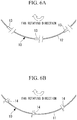
- Providing the draft angles as described above generally causes the ring member 10 to have level differences 13 and 14 due to the draft angles at the air inflow end 12 side along a b-b cross-section and at the air outflow end 11 side along a c-c cross-section in Fig. 3 , as shown in Fig. 6A and Fig. 6B , respectively.
- the level difference 13 at the air inflow end 12 formed along the b-b cross-section opposes the air flow as viewed from the rotating direction of the propeller fan 1 (the direction of the arrows in Figs. 3 , 6A, and 6B ), which makes the air flow turbulent, thus causing a decrease in efficiency and an increase in noise.
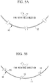
- the wall thickness of the cylindrical ring member 10 is adjusted to a thickness that does not form the level differences 13 on the outer circumferential surface side and the inner circumferential surface side of the ring member 10 at the air inflow end 12 side along the b-b cross-section of Fig. 3 within a permissible range, and the outer circumferential surface is provided with draft angles of, for example, about 0.5° toward the air outflow end 11 and the air inflow end 12 at the positive pressure surface 8 side and the negative pressure surface 9 side, with the blades 3 therebetween, respectively, as shown in Fig. 4 .
- draft angles provided at the inner circumferential surface side of the ring member 10, with the blades 3 therebetween are varied between the positive pressure surface 8 side and the negative pressure surface 9 side; for example, the draft angle provided at the positive pressure surface 8 side is set to about 1°, and the draft angle provided at the negative pressure surface 9 side is set to about 3°.
- Level differences 15 at the air outflow end 11 side caused by the difference in draft angle are concentrated at the inner circumferential surface side of the ring member 10, so that no level differences that act as resistance against the airflow remain on the ring member 10.
- the draft angle (1° or 3°) provided at the inner circumferential surface side of the ring member 10 is set larger than the draft angle (0.5°) provided at the outer circumferential surface side (1° or 3° > 0.5°) so that the molding die can easily be removed even if thermal shrinkage occurs during molding.
- the ring member 10 is provided at positions passing through the crests of the serrations 7 provided at the trailing edges 5 of the blades 3.
- this embodiment provides the following operational advantages.
- the plastic propeller fan 1 applied to automobile radiators and air-conditioning condensers is provided in an engine compartment and is influenced by vibrations, high temperature, water pressure due to water splashed during driving on a flooded road or the like. These act on the propeller fan 1 as external forces that tend to deform the blades 3.
- the cylindrical ring member 10 that joins the plurality of blades 3 together is provided to increase the strength of the blades 3, in particular, to provide a strength against deformation in the axial direction, thus preventing deformation of the propeller fan 1 due to the external forces described above.
- the reinforcing ring member 10 can be provided without limiting the shape of the outermost peripheries of the blades that provide the highest efficiency for the air blowing function of the propeller fan 1. This can ensure flexibility in designing the shape of the outermost peripheries of the blades and allows the basic performance of the propeller fan, such as the air blowing performance, efficiency, and noise performance, to be maintained.
- this embodiment can achieve both the effect of preventing deformation of the propeller fan 1 by increasing the strength of the blades 3 while firmly maintaining a low weight by keeping the wall thickness of the blades 3 small without increasing the wall thickness, as well as ensuring the basic performance of the propeller fan 1, such as the air blowing performance, efficiency, and noise performance.
- the ring member 10 is constituted of a cylindrical ring having a fixed width in the axial direction, an air flow rectifying effect can be provided, and in particular, a centripetal flow that is generated at the outer circumference of the fan, which is noticeable in a propeller fan that has a small depth dimension, can be reduced, so that a decrease in the effective radius of the fan can be prevented.
- the basic performance such as the air blowing performance, efficiency, and noise performance, can be improved.
- the ring member 10 since a level difference or the like that acts as resistance against the air flow is not created on the ring member 10 by designing the wall thickness and the draft angles of the cylindrical ring member 10, the ring member 10 does not exert an adverse influence on the fan performance etc. even with the configuration in which the cylindrical ring member 10 is integrally molded on the blades 3, and the propeller fan 1 with the cylindrical ring member can easily be manufactured by injection molding, as in the related art.
- the draft angles of the cylindrical ring member 10 are set such that the draft angle of the inner circumferential surface side is set larger than the draft angle of the outer circumferential surface side.
- the molding die can easily be removed because the draft angle of the inner circumferential surface side, which is influenced more by the thermal shrinkage, is larger. Accordingly, the propeller fan 1 with the cylindrical ring member can be manufactured without problems.
- the ring member 10 is provided at positions passing through the crests of the serrations 7 provided at the trailing edges 5 of the blades 3, the length of the ring member 10 in a cord longitudinal direction on the blades 3 can be maximized. This can maximize the effect of reinforcing the blades 3 using the ring member 10 and can avoid stress concentration on the troughs due to provision of the ring member 10 at the troughs of the serrations 7, thereby further enhancing reliability in increasing the strength.
- This example differs from the above-described first embodiment in the configuration of the ring member 20. Since the other features are the same as those of the first embodiment, descriptions thereof will be omitted.
- This example is configured such that the plurality of blades 3 are joined together with a rod-like ring member 20 that is circular, polygonal, or the like in cross-section, instead of the cylindrical ring member 10.
- This configuration in which the plurality of blades 3 are joined together with the rod-like ring member 20 in this way can also increase the strength of the blades 3, thus obtaining the effect of preventing deformation of the propeller fan 1.
- the ring member 20 is provided at a dimension position of 5 to 45 from the outer peripheral edge 6, excluding the outermost peripheries of the blades 3; therefore, the ring member 20 can be provided without limiting the shape of the outermost peripheries of the blades that provide the highest efficiency for the air blowing function of the propeller fan 1. This can ensure the basic performance of the propeller fan 1 and can also prevent deformation thereof.
- This embodiment differs from the above-described first embodiment in that an additional ring member 30 is provided in addition to the ring member 10. Since the other features are the same as those of the first embodiment, descriptions thereof will be omitted.
- This embodiment is configured such that another cylindrical ring member 30 is provided concentrically on the inner circumference side of the cylindrical ring member 10.
- Providing the cylindrical ring members 10 and 30 concentrically in multiple positions at two or more locations including a dimension position of 5 to 45 from the outer peripheral edge 6, excluding the outermost peripheries of the blades 3, as described above, can further enhance effects such as the reinforcing effect against deformation of the blades 3 in the axial direction, the airflow rectifying effect, and the preventive effect on reduction in the effective radius of the fan.
- the present invention is not limited to the invention according to the embodiments described above, and modifications can be made as appropriate within the scope of the appended claims.
- the draft angles provided on the cylindrical ring member 10 have been described using specific numerical values; however, it is needless to say that those are merely examples, and the present invention is not limited thereto.
- the shape and configuration of the blades 3 are not limited to those of the above embodiments, and various modifications may be made; for example, the blades need not have the serrations 7.
Landscapes
- Engineering & Computer Science (AREA)
- Mechanical Engineering (AREA)
- General Engineering & Computer Science (AREA)
- Structures Of Non-Positive Displacement Pumps (AREA)
Claims (4)
- Kunststoffpropellerlüfter (1), der eine Nabe (2) und mehrere Flügel (3) umfasst, die integral in einem radialen Muster am Außenumfang der Nabe (2) angeformt sind, wobei der Propellerlüfter (1) umfasst:ein zylindrisches Ringelement (10), das die mehreren Flügel (3) miteinander verbindet, wobei, unter der Annahme, dass die radiale Größe jedes Flügels (3) von der Basis zum Außenumfangsrand (6) 100 ist, das zylindrische Ringelement (10) an einer Abmessungsposition von 5 bis 45 von dem Außenumfangsrand (6) angeordnet ist,wobei das zylindrische Ringelement (10) die Form eines Zylinders hat, der eine feste Breite in der axialen Richtung aufweist,wobei der Propellerlüfter (1) so ausgebildet ist, dass ein Herstellungsformgesenk mit Teilungslinien zwischen benachbarten Flügeln (3) versehen werden kann und in ein Metallformwerkzeug, das eine Überdruckflächenseite (8) formt, und ein Metallformwerkzeug, das eine Unterdruckflächenseite (9) formt, mit den Flügeln (3) dazwischen, unterteilt werden kann,wobei das zylindrische Ringelement (10) mit einer Entformungsschräge in Richtung eines Luftausströmendes (11) des zylindrisches Ringelements (10) auf der Überdruckflächenseite (8) und einer Entformungsschräge in Richtung eines Lufteinströmendes (12) des zylindrischen Ringelements (10) auf einer Unterdruckflächenseite (9) versehen ist, undwobei die Wanddicke des zylindrischen Ringelements (10) so gewählt ist, dass kein Dickenniveauunterschied auf der Außenumfangsflächenseite und des Innenumfangsflächenseite des Ringelements (10) auf der Seite des Lufteinströmendes (12) entsteht, wobei der Kunststoffpropellerlüfter (1) dadurch gekennzeichnet ist, dass die Dickenniveauunterschiede (15) der Wand des zylindrischen Ringelements (10) auf der Seite des Luftausströmendes (11), die durch die unterschiedlichen Entformungsschrägen verursacht werden, auf der Innenumfangsflächenseite des Ringelements (10) konzentriert sind.
- Propellerlüfter nach Anspruch 1, wobei die Entformungsschräge auf der Innenumfangsflächenseite des zylindrischen Ringelements größer eingestellt ist als die Entformungsschräge auf der Außenumfangsflächenseite des zylindrischen Ringelements (10).
- Propellerlüfter nach einem der Ansprüche 1 oder 2, wobei das zylindrische Ringelement (10) an Positionen angeordnet ist, die durch die Spitzen eines Sägezahnmusters (7) verlaufen, das an den Hinterkanten der Flügel (3) angeordnet ist.
- Propellerlüfter nach einem der Ansprüche 1 bis 3, wobei zusätzlich zu dem zylindrischen Ringelement (10), das an der Abmessungsposition angeordnet ist, ein Ringelement (30) konzentrisch an mindestens einer Stelle auf seiner Innenumfangsseite angeordnet ist.
Applications Claiming Priority (2)
| Application Number | Priority Date | Filing Date | Title |
|---|---|---|---|
| JP2008109272A JP5422139B2 (ja) | 2008-04-18 | 2008-04-18 | プロペラファン |
| PCT/JP2009/057751 WO2009128529A1 (ja) | 2008-04-18 | 2009-04-17 | プロペラファン |
Publications (3)
| Publication Number | Publication Date |
|---|---|
| EP2264321A1 EP2264321A1 (de) | 2010-12-22 |
| EP2264321A4 EP2264321A4 (de) | 2017-12-13 |
| EP2264321B1 true EP2264321B1 (de) | 2019-01-02 |
Family
ID=41199216
Family Applications (1)
| Application Number | Title | Priority Date | Filing Date |
|---|---|---|---|
| EP09733424.7A Not-in-force EP2264321B1 (de) | 2008-04-18 | 2009-04-17 | Propellerlüfter aus kunststoff |
Country Status (4)
| Country | Link |
|---|---|
| US (1) | US8556587B2 (de) |
| EP (1) | EP2264321B1 (de) |
| JP (1) | JP5422139B2 (de) |
| WO (1) | WO2009128529A1 (de) |
Families Citing this family (36)
| Publication number | Priority date | Publication date | Assignee | Title |
|---|---|---|---|---|
| USD289525S (en) * | 1984-10-01 | 1987-04-28 | Industrial Tools, Inc. | Slicing machine for magnetic tape or the like |
| JP5128555B2 (ja) * | 2008-10-08 | 2013-01-23 | 日本電産サーボ株式会社 | インペラ及びファン装置 |
| JP5079035B2 (ja) * | 2010-02-15 | 2012-11-21 | 日本電産サーボ株式会社 | インペラ及び送風ファン |
| JP5534417B2 (ja) * | 2010-02-24 | 2014-07-02 | 日本電産サーボ株式会社 | 送風ファン |
| JP5095770B2 (ja) * | 2010-03-09 | 2012-12-12 | 日本電産サーボ株式会社 | 送風ファン |
| JP5252070B2 (ja) * | 2011-12-28 | 2013-07-31 | ダイキン工業株式会社 | 軸流ファン |
| US20130170995A1 (en) * | 2012-01-04 | 2013-07-04 | Ming-Ju Chen | Axial flow fan blade structure and axial flow fan thereof |
| ITBO20120042A1 (it) * | 2012-01-31 | 2013-08-01 | Comex Europ S R L | Dispositivo a ventola |
| JP6064487B2 (ja) * | 2012-09-24 | 2017-01-25 | 株式会社デンソー | 送風機 |
| WO2015029245A1 (ja) | 2013-09-02 | 2015-03-05 | 三菱電機株式会社 | プロペラファン、送風装置及び室外機 |
| CN203453120U (zh) * | 2013-09-03 | 2014-02-26 | 讯凯国际股份有限公司 | 风扇及其风扇叶轮 |
| DE102013223983A1 (de) * | 2013-11-25 | 2015-05-28 | Ebm-Papst Mulfingen Gmbh & Co. Kg | Lüfterbaueinheit |
| KR20150133077A (ko) * | 2014-05-19 | 2015-11-27 | 엘지전자 주식회사 | 송풍팬 및 이를 적용한 공기조화기 |
| JP6409666B2 (ja) * | 2014-09-18 | 2018-10-24 | 株式会社デンソー | 送風機 |
| EP4509722A3 (de) * | 2015-06-16 | 2025-04-23 | ResMed Pty Ltd | Laufrad mit geneigten und umgekehrt geneigten schaufeln |
| JP1573479S (de) * | 2016-01-27 | 2017-04-10 | ||
| USD804647S1 (en) * | 2016-02-02 | 2017-12-05 | Delta Electronics, Inc. | Fan blade |
| USD809121S1 (en) * | 2016-04-26 | 2018-01-30 | Parker-Hannifin Corporation | Fan with integral airflow guide |
| US10280935B2 (en) | 2016-04-26 | 2019-05-07 | Parker-Hannifin Corporation | Integral fan and airflow guide |
| TWD182168S (zh) * | 2016-07-27 | 2017-04-01 | 鑫賀精密電子(東莞)有限公司; | 風扇 |
| AU2017206193B2 (en) * | 2016-09-02 | 2023-07-27 | Fujitsu General Limited | Axial fan and outdoor unit |
| AU2016427676B2 (en) * | 2016-10-27 | 2019-11-14 | Mitsubishi Electric Corporation | Propeller fan, outdoor unit, and refrigeration cycle apparatus |
| CN106762828A (zh) * | 2017-01-19 | 2017-05-31 | 梁耀文 | 风机扇叶环形多级叶片结构 |
| CN109114019A (zh) * | 2017-06-23 | 2019-01-01 | 博格华纳公司 | 轴向风扇 |
| USD901669S1 (en) | 2017-09-29 | 2020-11-10 | Carrier Corporation | Contoured fan blade |
| CN207795681U (zh) * | 2018-01-13 | 2018-08-31 | 广东美的环境电器制造有限公司 | 轴流扇叶、轴流风机扇叶组件、轴流风机风道组件 |
| WO2020103400A1 (zh) * | 2018-11-22 | 2020-05-28 | 广东美的制冷设备有限公司 | 轴流风轮及具有其的空调器 |
| USD980965S1 (en) | 2019-05-07 | 2023-03-14 | Carrier Corporation | Leading edge of a fan blade |
| US11187083B2 (en) | 2019-05-07 | 2021-11-30 | Carrier Corporation | HVAC fan |
| CN110131190A (zh) * | 2019-06-21 | 2019-08-16 | 建纶电器工业(中山)有限公司 | 一种带支架的吊扇 |
| TWI725683B (zh) * | 2019-12-24 | 2021-04-21 | 建準電機工業股份有限公司 | 扇輪及具有該扇輪之散熱風扇 |
| CN115405538A (zh) * | 2021-05-28 | 2022-11-29 | 冷王公司 | 高效轴流式风扇 |
| US11808282B1 (en) | 2022-03-02 | 2023-11-07 | Aaon, Inc. | Propeller fan assembly with silencer seeds and concentric hub and method of use |
| WO2023216374A1 (zh) * | 2022-05-11 | 2023-11-16 | 赛诺韦尔科技有限公司 | 植物风扇灯 |
| WO2024057935A1 (ja) * | 2022-09-16 | 2024-03-21 | 株式会社Megaderu | 回転翼 |
| CN219413014U (zh) * | 2023-03-03 | 2023-07-25 | 广东美的环境电器制造有限公司 | 扇叶组件和风扇设备 |
Family Cites Families (18)
| Publication number | Priority date | Publication date | Assignee | Title |
|---|---|---|---|---|
| JPS5115210A (en) * | 1974-07-02 | 1976-02-06 | Rotoron Inc | Zatsuongenshono fuan |
| JPS58113899A (ja) * | 1981-12-28 | 1983-07-06 | 富士通株式会社 | エツクス線照射装置 |
| JPS58113899U (ja) * | 1982-01-29 | 1983-08-03 | 日産ディーゼル工業株式会社 | 軸流フアン |
| JPS62204000U (de) * | 1986-06-17 | 1987-12-26 | ||
| JPS6348996A (ja) * | 1986-08-18 | 1988-03-01 | Sanyo Electric Co Ltd | 電気信号中継器 |
| JPS6348996U (de) * | 1986-09-18 | 1988-04-02 | ||
| JPH02136597A (ja) * | 1988-11-15 | 1990-05-25 | Toshiba Corp | 送風羽根 |
| JPH08159090A (ja) | 1994-12-01 | 1996-06-18 | Sharp Corp | 軸流ファン |
| US20030012653A1 (en) * | 2001-07-13 | 2003-01-16 | Guy Diemunsch | Cooling fan |
| JP2003035296A (ja) * | 2001-07-24 | 2003-02-07 | Daikin Ind Ltd | プロペラファンの製造方法 |
| US6899525B2 (en) * | 2002-07-22 | 2005-05-31 | Arthur Vanmoor | Blade and wing configuration |
| JP4085948B2 (ja) | 2003-10-01 | 2008-05-14 | 株式会社デンソー | 冷却ファンおよび送風機 |
| JP4519734B2 (ja) * | 2005-08-03 | 2010-08-04 | 三菱重工業株式会社 | 回転翼車及びプロペラファン |
| US7815418B2 (en) * | 2005-08-03 | 2010-10-19 | Mitsubishi Heavy Industries, Ltd. | Shroud and rotary vane wheel of propeller fan and propeller fan |
| US20070128038A1 (en) * | 2005-12-01 | 2007-06-07 | Nett Jonathan M | Engine cooling fan with ring reinforcement |
| TW200811375A (en) * | 2006-08-30 | 2008-03-01 | Delta Electronics Inc | Fan and impeller thereof |
| US8342808B2 (en) | 2006-12-11 | 2013-01-01 | Mitsuba Corporation | Cooling fan |
| WO2009036403A2 (en) * | 2007-09-13 | 2009-03-19 | Borgwarner Inc. | Fan with structural support ring |
-
2008
- 2008-04-18 JP JP2008109272A patent/JP5422139B2/ja not_active Expired - Fee Related
-
2009
- 2009-04-17 WO PCT/JP2009/057751 patent/WO2009128529A1/ja not_active Ceased
- 2009-04-17 EP EP09733424.7A patent/EP2264321B1/de not_active Not-in-force
- 2009-04-17 US US12/747,043 patent/US8556587B2/en not_active Expired - Fee Related
Non-Patent Citations (1)
| Title |
|---|
| None * |
Also Published As
| Publication number | Publication date |
|---|---|
| EP2264321A1 (de) | 2010-12-22 |
| EP2264321A4 (de) | 2017-12-13 |
| JP2009257260A (ja) | 2009-11-05 |
| US8556587B2 (en) | 2013-10-15 |
| WO2009128529A1 (ja) | 2009-10-22 |
| JP5422139B2 (ja) | 2014-02-19 |
| US20100260608A1 (en) | 2010-10-14 |
Similar Documents
| Publication | Publication Date | Title |
|---|---|---|
| EP2264321B1 (de) | Propellerlüfter aus kunststoff | |
| EP3290715B1 (de) | Axiallüfter und ausseneinheit | |
| EP3299632B1 (de) | Axiallüfter und ausseneinheit damit | |
| EP2492514B1 (de) | Wärmetauschmodul für fahrzeuge | |
| KR100332539B1 (ko) | 축류팬 | |
| US8512004B2 (en) | Propeller fan | |
| US8550782B2 (en) | Partial ring cooling fan | |
| US5399070A (en) | Fan hub | |
| US20170261000A1 (en) | Blower | |
| US10563664B2 (en) | Fan impeller and radiator fan module | |
| KR20000023522A (ko) | 축류 송풍기 | |
| US10844868B2 (en) | Free-tipped axial fan assembly | |
| US10823042B2 (en) | Air blowing fan device | |
| US20110014052A1 (en) | Fan with structural support ring | |
| EP2539591B1 (de) | Axiallüfteranordnung mit freien spitzen | |
| JP5357492B2 (ja) | プロペラファン | |
| JP2007113474A (ja) | 送風機 | |
| US9790955B2 (en) | Impeller for motor vehicle fan, including segmented hub stiffeners | |
| KR100663965B1 (ko) | 축류팬 | |
| KR102035317B1 (ko) | 축류 팬 | |
| US9074515B2 (en) | Vehicle heat-exchange module | |
| JP2017110563A (ja) | 送風装置 | |
| US20180223862A1 (en) | Axial fan | |
| JP2017031944A (ja) | 軸流送風機 | |
| JP2005201203A (ja) | 多翼ファン |
Legal Events
| Date | Code | Title | Description |
|---|---|---|---|
| PUAI | Public reference made under article 153(3) epc to a published international application that has entered the european phase |
Free format text: ORIGINAL CODE: 0009012 |
|
| 17P | Request for examination filed |
Effective date: 20100616 |
|
| AK | Designated contracting states |
Kind code of ref document: A1 Designated state(s): AT BE BG CH CY CZ DE DK EE ES FI FR GB GR HR HU IE IS IT LI LT LU LV MC MK MT NL NO PL PT RO SE SI SK TR |
|
| AX | Request for extension of the european patent |
Extension state: AL BA RS |
|
| DAX | Request for extension of the european patent (deleted) | ||
| RA4 | Supplementary search report drawn up and despatched (corrected) |
Effective date: 20171115 |
|
| RIC1 | Information provided on ipc code assigned before grant |
Ipc: B29C 45/00 20060101ALN20171109BHEP Ipc: F04D 29/66 20060101ALI20171109BHEP Ipc: F04D 29/34 20060101ALI20171109BHEP Ipc: F04D 29/32 20060101AFI20171109BHEP Ipc: F04D 29/38 20060101ALI20171109BHEP |
|
| GRAP | Despatch of communication of intention to grant a patent |
Free format text: ORIGINAL CODE: EPIDOSNIGR1 |
|
| STAA | Information on the status of an ep patent application or granted ep patent |
Free format text: STATUS: GRANT OF PATENT IS INTENDED |
|
| RIC1 | Information provided on ipc code assigned before grant |
Ipc: B29C 45/00 20060101ALN20180626BHEP Ipc: B29C 33/44 20060101ALI20180626BHEP Ipc: B29C 33/00 20060101ALN20180626BHEP Ipc: B29L 31/08 20060101ALN20180626BHEP Ipc: F04D 29/34 20060101ALI20180626BHEP Ipc: F04D 29/32 20060101AFI20180626BHEP Ipc: F04D 29/38 20060101ALI20180626BHEP Ipc: F04D 29/66 20060101ALI20180626BHEP |
|
| INTG | Intention to grant announced |
Effective date: 20180726 |
|
| RIN1 | Information on inventor provided before grant (corrected) |
Inventor name: SUZUKI, ATSUSHI Inventor name: KAMIYA, KAZUYUKI Inventor name: KOBAYASHI, TAKAYUKI |
|
| GRAS | Grant fee paid |
Free format text: ORIGINAL CODE: EPIDOSNIGR3 |
|
| GRAA | (expected) grant |
Free format text: ORIGINAL CODE: 0009210 |
|
| STAA | Information on the status of an ep patent application or granted ep patent |
Free format text: STATUS: THE PATENT HAS BEEN GRANTED |
|
| AK | Designated contracting states |
Kind code of ref document: B1 Designated state(s): AT BE BG CH CY CZ DE DK EE ES FI FR GB GR HR HU IE IS IT LI LT LU LV MC MK MT NL NO PL PT RO SE SI SK TR |
|
| REG | Reference to a national code |
Ref country code: GB Ref legal event code: FG4D |
|
| REG | Reference to a national code |
Ref country code: CH Ref legal event code: EP Ref country code: AT Ref legal event code: REF Ref document number: 1084735 Country of ref document: AT Kind code of ref document: T Effective date: 20190115 |
|
| REG | Reference to a national code |
Ref country code: IE Ref legal event code: FG4D |
|
| REG | Reference to a national code |
Ref country code: DE Ref legal event code: R096 Ref document number: 602009056503 Country of ref document: DE |
|
| REG | Reference to a national code |
Ref country code: NL Ref legal event code: MP Effective date: 20190102 |
|
| REG | Reference to a national code |
Ref country code: LT Ref legal event code: MG4D |
|
| REG | Reference to a national code |
Ref country code: AT Ref legal event code: MK05 Ref document number: 1084735 Country of ref document: AT Kind code of ref document: T Effective date: 20190102 |
|
| PG25 | Lapsed in a contracting state [announced via postgrant information from national office to epo] |
Ref country code: NL Free format text: LAPSE BECAUSE OF FAILURE TO SUBMIT A TRANSLATION OF THE DESCRIPTION OR TO PAY THE FEE WITHIN THE PRESCRIBED TIME-LIMIT Effective date: 20190102 |
|
| PG25 | Lapsed in a contracting state [announced via postgrant information from national office to epo] |
Ref country code: ES Free format text: LAPSE BECAUSE OF FAILURE TO SUBMIT A TRANSLATION OF THE DESCRIPTION OR TO PAY THE FEE WITHIN THE PRESCRIBED TIME-LIMIT Effective date: 20190102 Ref country code: PL Free format text: LAPSE BECAUSE OF FAILURE TO SUBMIT A TRANSLATION OF THE DESCRIPTION OR TO PAY THE FEE WITHIN THE PRESCRIBED TIME-LIMIT Effective date: 20190102 Ref country code: LT Free format text: LAPSE BECAUSE OF FAILURE TO SUBMIT A TRANSLATION OF THE DESCRIPTION OR TO PAY THE FEE WITHIN THE PRESCRIBED TIME-LIMIT Effective date: 20190102 Ref country code: NO Free format text: LAPSE BECAUSE OF FAILURE TO SUBMIT A TRANSLATION OF THE DESCRIPTION OR TO PAY THE FEE WITHIN THE PRESCRIBED TIME-LIMIT Effective date: 20190402 Ref country code: PT Free format text: LAPSE BECAUSE OF FAILURE TO SUBMIT A TRANSLATION OF THE DESCRIPTION OR TO PAY THE FEE WITHIN THE PRESCRIBED TIME-LIMIT Effective date: 20190502 Ref country code: FI Free format text: LAPSE BECAUSE OF FAILURE TO SUBMIT A TRANSLATION OF THE DESCRIPTION OR TO PAY THE FEE WITHIN THE PRESCRIBED TIME-LIMIT Effective date: 20190102 Ref country code: SE Free format text: LAPSE BECAUSE OF FAILURE TO SUBMIT A TRANSLATION OF THE DESCRIPTION OR TO PAY THE FEE WITHIN THE PRESCRIBED TIME-LIMIT Effective date: 20190102 |
|
| PG25 | Lapsed in a contracting state [announced via postgrant information from national office to epo] |
Ref country code: HR Free format text: LAPSE BECAUSE OF FAILURE TO SUBMIT A TRANSLATION OF THE DESCRIPTION OR TO PAY THE FEE WITHIN THE PRESCRIBED TIME-LIMIT Effective date: 20190102 Ref country code: BG Free format text: LAPSE BECAUSE OF FAILURE TO SUBMIT A TRANSLATION OF THE DESCRIPTION OR TO PAY THE FEE WITHIN THE PRESCRIBED TIME-LIMIT Effective date: 20190402 Ref country code: GR Free format text: LAPSE BECAUSE OF FAILURE TO SUBMIT A TRANSLATION OF THE DESCRIPTION OR TO PAY THE FEE WITHIN THE PRESCRIBED TIME-LIMIT Effective date: 20190403 Ref country code: IS Free format text: LAPSE BECAUSE OF FAILURE TO SUBMIT A TRANSLATION OF THE DESCRIPTION OR TO PAY THE FEE WITHIN THE PRESCRIBED TIME-LIMIT Effective date: 20190502 Ref country code: LV Free format text: LAPSE BECAUSE OF FAILURE TO SUBMIT A TRANSLATION OF THE DESCRIPTION OR TO PAY THE FEE WITHIN THE PRESCRIBED TIME-LIMIT Effective date: 20190102 |
|
| REG | Reference to a national code |
Ref country code: DE Ref legal event code: R097 Ref document number: 602009056503 Country of ref document: DE |
|
| PG25 | Lapsed in a contracting state [announced via postgrant information from national office to epo] |
Ref country code: EE Free format text: LAPSE BECAUSE OF FAILURE TO SUBMIT A TRANSLATION OF THE DESCRIPTION OR TO PAY THE FEE WITHIN THE PRESCRIBED TIME-LIMIT Effective date: 20190102 Ref country code: SK Free format text: LAPSE BECAUSE OF FAILURE TO SUBMIT A TRANSLATION OF THE DESCRIPTION OR TO PAY THE FEE WITHIN THE PRESCRIBED TIME-LIMIT Effective date: 20190102 Ref country code: RO Free format text: LAPSE BECAUSE OF FAILURE TO SUBMIT A TRANSLATION OF THE DESCRIPTION OR TO PAY THE FEE WITHIN THE PRESCRIBED TIME-LIMIT Effective date: 20190102 Ref country code: CZ Free format text: LAPSE BECAUSE OF FAILURE TO SUBMIT A TRANSLATION OF THE DESCRIPTION OR TO PAY THE FEE WITHIN THE PRESCRIBED TIME-LIMIT Effective date: 20190102 Ref country code: IT Free format text: LAPSE BECAUSE OF FAILURE TO SUBMIT A TRANSLATION OF THE DESCRIPTION OR TO PAY THE FEE WITHIN THE PRESCRIBED TIME-LIMIT Effective date: 20190102 Ref country code: AT Free format text: LAPSE BECAUSE OF FAILURE TO SUBMIT A TRANSLATION OF THE DESCRIPTION OR TO PAY THE FEE WITHIN THE PRESCRIBED TIME-LIMIT Effective date: 20190102 Ref country code: DK Free format text: LAPSE BECAUSE OF FAILURE TO SUBMIT A TRANSLATION OF THE DESCRIPTION OR TO PAY THE FEE WITHIN THE PRESCRIBED TIME-LIMIT Effective date: 20190102 |
|
| PLBE | No opposition filed within time limit |
Free format text: ORIGINAL CODE: 0009261 |
|
| STAA | Information on the status of an ep patent application or granted ep patent |
Free format text: STATUS: NO OPPOSITION FILED WITHIN TIME LIMIT |
|
| REG | Reference to a national code |
Ref country code: CH Ref legal event code: PL |
|
| 26N | No opposition filed |
Effective date: 20191003 |
|
| REG | Reference to a national code |
Ref country code: BE Ref legal event code: MM Effective date: 20190430 |
|
| GBPC | Gb: european patent ceased through non-payment of renewal fee |
Effective date: 20190417 |
|
| PG25 | Lapsed in a contracting state [announced via postgrant information from national office to epo] |
Ref country code: MC Free format text: LAPSE BECAUSE OF FAILURE TO SUBMIT A TRANSLATION OF THE DESCRIPTION OR TO PAY THE FEE WITHIN THE PRESCRIBED TIME-LIMIT Effective date: 20190102 Ref country code: LU Free format text: LAPSE BECAUSE OF NON-PAYMENT OF DUE FEES Effective date: 20190417 |
|
| PG25 | Lapsed in a contracting state [announced via postgrant information from national office to epo] |
Ref country code: GB Free format text: LAPSE BECAUSE OF NON-PAYMENT OF DUE FEES Effective date: 20190417 Ref country code: LI Free format text: LAPSE BECAUSE OF NON-PAYMENT OF DUE FEES Effective date: 20190430 Ref country code: CH Free format text: LAPSE BECAUSE OF NON-PAYMENT OF DUE FEES Effective date: 20190430 |
|
| PG25 | Lapsed in a contracting state [announced via postgrant information from national office to epo] |
Ref country code: SI Free format text: LAPSE BECAUSE OF FAILURE TO SUBMIT A TRANSLATION OF THE DESCRIPTION OR TO PAY THE FEE WITHIN THE PRESCRIBED TIME-LIMIT Effective date: 20190102 Ref country code: BE Free format text: LAPSE BECAUSE OF NON-PAYMENT OF DUE FEES Effective date: 20190430 Ref country code: FR Free format text: LAPSE BECAUSE OF NON-PAYMENT OF DUE FEES Effective date: 20190430 |
|
| PG25 | Lapsed in a contracting state [announced via postgrant information from national office to epo] |
Ref country code: TR Free format text: LAPSE BECAUSE OF FAILURE TO SUBMIT A TRANSLATION OF THE DESCRIPTION OR TO PAY THE FEE WITHIN THE PRESCRIBED TIME-LIMIT Effective date: 20190102 |
|
| PG25 | Lapsed in a contracting state [announced via postgrant information from national office to epo] |
Ref country code: IE Free format text: LAPSE BECAUSE OF NON-PAYMENT OF DUE FEES Effective date: 20190417 |
|
| PGFP | Annual fee paid to national office [announced via postgrant information from national office to epo] |
Ref country code: DE Payment date: 20200408 Year of fee payment: 12 |
|
| PG25 | Lapsed in a contracting state [announced via postgrant information from national office to epo] |
Ref country code: CY Free format text: LAPSE BECAUSE OF FAILURE TO SUBMIT A TRANSLATION OF THE DESCRIPTION OR TO PAY THE FEE WITHIN THE PRESCRIBED TIME-LIMIT Effective date: 20190102 |
|
| PG25 | Lapsed in a contracting state [announced via postgrant information from national office to epo] |
Ref country code: HU Free format text: LAPSE BECAUSE OF FAILURE TO SUBMIT A TRANSLATION OF THE DESCRIPTION OR TO PAY THE FEE WITHIN THE PRESCRIBED TIME-LIMIT; INVALID AB INITIO Effective date: 20090417 Ref country code: MT Free format text: LAPSE BECAUSE OF FAILURE TO SUBMIT A TRANSLATION OF THE DESCRIPTION OR TO PAY THE FEE WITHIN THE PRESCRIBED TIME-LIMIT Effective date: 20190102 |
|
| REG | Reference to a national code |
Ref country code: DE Ref legal event code: R119 Ref document number: 602009056503 Country of ref document: DE |
|
| PG25 | Lapsed in a contracting state [announced via postgrant information from national office to epo] |
Ref country code: DE Free format text: LAPSE BECAUSE OF NON-PAYMENT OF DUE FEES Effective date: 20211103 |
|
| PG25 | Lapsed in a contracting state [announced via postgrant information from national office to epo] |
Ref country code: MK Free format text: LAPSE BECAUSE OF FAILURE TO SUBMIT A TRANSLATION OF THE DESCRIPTION OR TO PAY THE FEE WITHIN THE PRESCRIBED TIME-LIMIT Effective date: 20190102 |