EP2264274A2 - Échelle télescopique - Google Patents
Échelle télescopique Download PDFInfo
- Publication number
- EP2264274A2 EP2264274A2 EP10005333A EP10005333A EP2264274A2 EP 2264274 A2 EP2264274 A2 EP 2264274A2 EP 10005333 A EP10005333 A EP 10005333A EP 10005333 A EP10005333 A EP 10005333A EP 2264274 A2 EP2264274 A2 EP 2264274A2
- Authority
- EP
- European Patent Office
- Prior art keywords
- locking
- spar
- actuating
- coupling
- locking unit
- Prior art date
- Legal status (The legal status is an assumption and is not a legal conclusion. Google has not performed a legal analysis and makes no representation as to the accuracy of the status listed.)
- Withdrawn
Links
- 230000008878 coupling Effects 0.000 claims description 43
- 238000010168 coupling process Methods 0.000 claims description 43
- 238000005859 coupling reaction Methods 0.000 claims description 43
- 230000000903 blocking effect Effects 0.000 claims description 26
- 230000015572 biosynthetic process Effects 0.000 claims description 5
- 230000004913 activation Effects 0.000 claims description 4
- 239000004020 conductor Substances 0.000 abstract description 6
- 238000000034 method Methods 0.000 description 5
- 235000003332 Ilex aquifolium Nutrition 0.000 description 4
- 241000209027 Ilex aquifolium Species 0.000 description 4
- 230000001427 coherent effect Effects 0.000 description 2
- 230000000694 effects Effects 0.000 description 1
- 238000007493 shaping process Methods 0.000 description 1
- 239000000725 suspension Substances 0.000 description 1
Images


Classifications
-
- E—FIXED CONSTRUCTIONS
- E06—DOORS, WINDOWS, SHUTTERS, OR ROLLER BLINDS IN GENERAL; LADDERS
- E06C—LADDERS
- E06C1/00—Ladders in general
- E06C1/02—Ladders in general with rigid longitudinal member or members
- E06C1/04—Ladders for resting against objects, e.g. walls poles, trees
- E06C1/08—Ladders for resting against objects, e.g. walls poles, trees multi-part
- E06C1/12—Ladders for resting against objects, e.g. walls poles, trees multi-part extensible, e.g. telescopic
- E06C1/125—Ladders for resting against objects, e.g. walls poles, trees multi-part extensible, e.g. telescopic with tubular longitudinal members nested within each other
-
- F—MECHANICAL ENGINEERING; LIGHTING; HEATING; WEAPONS; BLASTING
- F16—ENGINEERING ELEMENTS AND UNITS; GENERAL MEASURES FOR PRODUCING AND MAINTAINING EFFECTIVE FUNCTIONING OF MACHINES OR INSTALLATIONS; THERMAL INSULATION IN GENERAL
- F16B—DEVICES FOR FASTENING OR SECURING CONSTRUCTIONAL ELEMENTS OR MACHINE PARTS TOGETHER, e.g. NAILS, BOLTS, CIRCLIPS, CLAMPS, CLIPS OR WEDGES; JOINTS OR JOINTING
- F16B7/00—Connections of rods or tubes, e.g. of non-circular section, mutually, including resilient connections
- F16B7/10—Telescoping systems
- F16B7/105—Telescoping systems locking in discrete positions, e.g. in extreme extended position
Definitions
- the present invention relates to a telescopic ladder according to the preamble of claim 1.
- Telescopic ladders are used today in all areas in which a high degree of flexibility is required and only little storage space is available.
- the budgetary area is in the foreground in this context. This is not to be understood as limiting.
- the well-known ladder ( EP 0 527 766 B1 ), from which the invention proceeds, is configured in the usual way with two adjacent spars and arranged between the spars rungs.
- the spars each consist of a plurality of tubular spar sections which telescope telescopically. Two adjacent spar sections are connected to each other via a rung.
- the ladder can be brought into a retracted position and into an extended position. In the retracted position, all spar sections are interlaced so that, with the exception of the lowest rung, all rungs abut each other. In the retracted position, the ladder is compact and easy to transport and stow.
- each locking unit In the rungs are each locking units, with which the rung associated spar sections relative to the next higher rail section are locked. This allows the ladder to lock altogether in its extended position.
- the invention is based on the problem, the known telescopic ladder in such a way and further develop that the ease of use and user safety can be increased.
- the spar sections each have a locking unit with which the spar sections can be locked against the respective next lower spar section in the respective extended position.
- actuating shaft which extends longitudinally within the respective spar and which is in engagement with or engageable with at least one locking unit.
- the actuating shaft is assigned according to a manual actuator.
- the actuating shaft engages with the locking unit of the uppermost extended spar portion, and not with locking units of other extended spar portions. This means that only the respective uppermost extended spar section is detachable by means of the actuating shaft. This in turn means that the retraction of the ladder by means of the actuator rung by rung, starting with the top rung, in the order from top to bottom takes place gradually. Each step is with an actuation of the actuator connected. The retraction of the ladder can thus be interrupted at any time for further use of the ladder.
- a coherent, non-separable rung pack can form exclusively at the upper end of the ladder. This also complies with the applicable safety regulations, as such, located at the bottom of the ladder rung package can form a tripping hazard to the user.
- the proposed ladder is equipped in a conventional manner with two side bars 1 and 1 arranged between the bars 1 rungs 2.
- the spars 1 each consist of a plurality of substantially tubular, telescopically intermeshing spar sections 3, wherein adjacent spar sections 3 are connected to each other via a rung 2. This is a synopsis of Fig. 1 and 6 refer to.
- the spar sections 3 each have a locking unit 4, with which the spar sections 3 can be locked against the respective next lower spar section 3 in the respective extended position.
- An exception is the fixed spar section 3f, which of course is retractable in no next lower spar section.
- this is the lowest spar section 3f, to which a foot element of the ladder is assigned.
- the two lowest rail sections 3f are additionally connected to each other by an initial rung 2g ( Fig. 5 ).
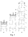
- Fig. 1a shows the retracted position of the ladder, in which all rail sections 3 are retracted.
- Fig. 1b shows a partially retracted position, in which only the spar sections 3a-c are retracted and in the other spar sections 3d, e are locked against the next lower Holmabête 3e, f.
- Fig. 1c shows the extended position of the ladder, in which the spar sections 3a-e are locked with the respective next lower spar sections 3b-f.
- the two bars 1 are each assigned a manual actuating device 5 for releasing the locking units 4 and that the actuating device 5 has an actuating shaft 6 which extends longitudinally within the respective spar 1 and in particular in dependence on the Teleskopierlage the Ladder is engaged with at least one locking unit 4 or can be brought.
- a synopsis of Fig. 4 and 5 shows that the operating shaft 6 depending on the telescoping position of the ladder can only be engaged with the locking unit 4a or with other locking units 4.
- the locking units 4 are rigidly connected to the spar sections 3 otherwise. Thus, if a spar section 3 is extended or retracted, the associated locking unit 4 performs the same movement.
- the operation preferably takes place from the upper end of the ladder.
- the actuating device 5 at the upper end of the respective spar 1 each have a rotary actuating handle 7, which is drivingly coupled to the actuating shaft 6.
- the rotary actuating handle 7 is simply placed on the actuating shaft 6.
- a rotation of the rotary actuating handle 7 correspondingly leads to a rotation of the actuating shaft 6 and as a result to the release of the respective locking units 4.
- the rotary actuating movement and the subsequent retraction are in Fig. 2 represented by arrows.
- rotational movement are here quite generally detected both rotational movements in the strict sense and pivotal movements.
- actuating shaft 6 extends there from the upper end of the respective spar 1 with a free end 6a downwards, wherein here and preferably the actuating shaft 6 in the uppermost Holmabêt 3a is mounted axially fixed and rotatable.
- the actuating shaft 6 follows the retraction of the uppermost spar section 3a.
- the interpretation of the length of the actuating shaft 6 for the function of the ladder has a very special meaning.
- the actuating shaft 6 is designed in particular with regard to their length so that it is in engagement with the locking unit 4 of the respective uppermost extended spar section 3, and not with locking units 4 of other extended spar sections 3. This ensures that only the respective uppermost extended spar section 3 can be released with the actuating device 5. This corresponds to the in Fig. 3 shown procedure when retracting the ladder.
- the length of the spar sections 3 is preferably about 1.5 times the distance between two rungs 2 when the ladder is extended. This ensures an overlap of the spar sections 3 of approximately half the distance between two rungs 2, which is important for the stability of the ladder.
- the length of the actuating shaft is approximately twice the distance between two rungs 2 when the ladder is extended. In any case, it is inevitable here that the length of the actuating shaft 6 is smaller than the height of the conductor located in the retracted position.
- the locking units 4 of the spar sections 3 each have an activatable coupling unit 8 for their coupling with a further locking unit 4.
- this further locking unit 4 is here and preferably always to the locking unit 4 of the next higher, retracted Holmabitess 3.
- the locking units 4a of the upper rail sections 3a are not equipped with such a coupling unit 8.
- the coupling acts here in the extension direction of the respective spar 1.
- the Fig. 7 to 10 show the locking units 4 in the assembled state in detail.
- the locking units 4 illustrated there are the locking units 4a of the uppermost spar sections 3a (FIG. Fig. 7, 8 ) and in addition to the locking units 4b of the next lower rail sections 3b ( Fig. 9, 10th ).
- the design of the respective items can be the Fig. 11 and 12 remove.
- the local locking unit 4a has an adjustable locking element 9 for the positive locking against the next lower rail section, here against the spar section 3b.
- the locking element 9 is depending on the locking state in a locking position ( Fig. 7a )) or in a release position ( Fig. 8a )).
- the locking element engages 9 for locking with the next lower rail section 3b in a local Vernegelungsausformung 10, which is designed here and preferably as a simple hole in the spar section 3b.
- the locking element 9 is correspondingly in the locking position.
- the locking can be provided shaping 10 at different locations on the respective rail section 3.
- the locking formation 10 is in each case arranged between two rungs 2 when the ladder is extended. This can be, for example, the representation in Fig. 6 remove.
- the locking element 9 can now be adjusted by means of the actuating device 5 via the actuating shaft 6 in the release position, in which the locking element 9 is disengaged from the Vernegelungsausformung 10. This is for example in Fig. 8a ). It is further preferably so that the locking element 9 is biased in the locking position by a spring element 19.
- the coupling unit 8 of the locking unit 4b is in the Fig. 9 and 10 shown.
- the coupling unit 8 has there an adjustable coupling element 11 for the positive coupling with a further locking unit 4a, wherein the coupling element 11 depending on the coupling state in an activated position ( Fig. 10 ) or in a deactivated position ( Fig. 9 ) stands.
- the coupling element 11 engages with a coupling formation 12 of the further locking unit 4a.
- FIG. 12 A look at the Fig. 12 shows that the coupling element 11 is here and preferably integrally connected to the locking element 9, so that the release the locking unit 4 is always accompanied by an activation of the coupling unit 8.
- the coupling element 11 is here and preferably integrally connected to the locking element 9, so that the release the locking unit 4 is always accompanied by an activation of the coupling unit 8.
- the coupling element 11 is here and preferably integrally connected to the locking element 9, so that the release the locking unit 4 is always accompanied by an activation of the coupling unit 8.
- the coupling element 11 is here and preferably integrally connected to the locking element 9, so that the release the locking unit 4 is always accompanied by an activation of the coupling unit 8.
- the coupling element 11 is here and preferably integrally connected to the locking element 9, so that the release the locking unit 4 is always accompanied by an activation of the coupling unit 8.
- the coupling element 11 is here and preferably integrally connected to the locking element 9, so that the release the locking unit 4 is always accompanied by
- the locking element 9 and the coupling element 11 are arranged on an actuating slide 13, wherein the actuating slide 13 is adjustable in the context of an actuation by the actuating device 5 substantially perpendicular to the extension of the respective spar 1. This is best done with a synopsis of the Fig. 11 and 12 remove. In principle, it can also be provided that only one of the components locking element or coupling element is arranged on the actuating slide 13. It is also conceivable realization of two mutually coupled actuating carriage.
- the mechanical interface between the actuating shaft 6 and the respective locking unit 4 is preferably realized in that the locking unit 4 has a rotatable actuating element 14, which is further preferably designed as a Betuschistssexzenter.
- the actuating element 14 is equipped with an eccentric 14a, which cooperates with a arranged on the actuating carriage 13 driver 14b.
- the actuating element 14 now has a driving opening 15 aligned with the actuating shaft axis, with which the actuating shaft 6 comes into driving engagement when the respective rail section 3 retracts and through which the actuating shaft 6 can be passed. It is preferably such that the actuating shaft 6 during retraction of the respective spar section 3 axially movable, but rotatably comes with the driving opening 15 of the actuating element 14 into engagement.
- the realization of a corresponding positive connection between the actuating shaft 6 and the actuating element 14 is advantageous.
- the driving opening 15 on the one hand and the actuating shaft 6 on the other hand be configured in cross section in the manner of a square or hexagonal profile or in the manner of a pinion. Other form-fitting connections are conceivable.
- the locking units 4 of the illustrated embodiment still have a special feature with which the reliability of the proposed ladder is further increased.
- this feature is namely avoided that the locking elements 9, here the locking pin 9, are pressed out of the Vernegelungsausformungen 10 in case of improper use from the outside.
- Fig. 7a shows that pushing out of the locking element 9, in the representation there to the right, would in principle be possible by the accessibility of the locking element 9 from the outside.
- the locking unit 4 has an adjustable blocking element 16 which blocks an adjustment of the locking element 9 out of the locking position, wherein a first rotation of the actuating element 14 in the context of the actuation causes the blocking by the blocking element 16 to be canceled.
- the blocking element 16 always has a blocking effect on the locking element 9 as long as a first rotation of the actuating element 14 has not yet taken place.
- FIG. 7 to 12 A preferred realization of the above blocking of the locking element 9 can be seen in the Fig. 7 to 12 remove.
- the blocking element 16 is pivotably articulated to the actuating slide 13 here. This shows, for example, a synopsis of Fig. 11 and 12 , The operation of the blocking element 16 is best shown in the representation in Fig. 7 , Without actuation, the locking element 9 is in the locking position and the blocking element 16 in the blocking position.
- the blocking element is in Fig. 7a ) pivoted downwards. Is now on the locking element 9, a force in Fig. 7a ) is exerted to the right, then comes a blocking surface 16a of the blocking element 16 into engagement with a shoulder 17 of the housing 18 of the locking unit 4a. By the articulation of the blocking element 16 on the actuating slide 13, the adjustment of the actuating carriage 13 is blocked.
- a link 14c ( Fig. 11 ) engages with a guide surface 16b of the blocking element 16 and pushes the blocking element 16 into the in Fig. 7b ) shown position. This is preferably done against the force of a spring element, not shown. Subsequently, it is possible, the actuating carriage 13 in Fig. 7b ) to move to the right. In this case, the blocking surface 16a of the blocking element 16 runs past the shoulder 17 of the housing 18.
- unactuated state causes a first rotation of the rotary operating handle 7 in the in Fig. 7b Initially, the blocking is blocked by the blocking element 16.
- the eccentric 14a engages with the driver 14b and thus causes an adjustment of the locking element 9 into the release position (FIG. Fig. 8a )).
- the locking unit 4a engages with the locking unit 4b of the next lower spar section 3b.
- the actuating shaft 6 still penetrates the actuating element 14 of the locking unit 4b, so that a first actuation first of all causes the blocking to be released by the blocking element 16 there ( Fig. 9b )).
- the locking element 9 of the locking unit 4b is now transferred into the release position ( Fig. 10a )).
- the coupling element 11 of the locking unit 4b comes into engagement with the coupling formation 12 of the locking unit 4a.
- the spar section 3b can be lowered into the next lower spar section 3c ( Fig. 10b )).
- the locking element 9 of the locking unit 4b slides on the inside of the spar portion 3c along, the coupling element 11 remains in the activated position.
- the two locking units 4a, 4b are coupled together until further notice.
Applications Claiming Priority (1)
| Application Number | Priority Date | Filing Date | Title |
|---|---|---|---|
| DE202009007991U DE202009007991U1 (de) | 2009-06-05 | 2009-06-05 | Teleskopierbare Leiter |
Publications (2)
| Publication Number | Publication Date |
|---|---|
| EP2264274A2 true EP2264274A2 (fr) | 2010-12-22 |
| EP2264274A3 EP2264274A3 (fr) | 2015-04-15 |
Family
ID=42244991
Family Applications (1)
| Application Number | Title | Priority Date | Filing Date |
|---|---|---|---|
| EP10005333.9A Withdrawn EP2264274A3 (fr) | 2009-06-05 | 2010-05-21 | Échelle télescopique |
Country Status (4)
| Country | Link |
|---|---|
| US (1) | US20100307870A1 (fr) |
| EP (1) | EP2264274A3 (fr) |
| CN (1) | CN101906930B (fr) |
| DE (1) | DE202009007991U1 (fr) |
Families Citing this family (10)
| Publication number | Priority date | Publication date | Assignee | Title |
|---|---|---|---|---|
| CN101050687B (zh) * | 2007-05-22 | 2011-02-23 | 王克诚 | 可伸缩梯子及其直立组合式梯子、平台高凳和人字梯 |
| CA2624211A1 (fr) * | 2008-03-04 | 2009-09-04 | Dean Lepage | Support extensible portatif pour arbre |
| US8844674B2 (en) * | 2011-08-19 | 2014-09-30 | Collin Smith | Assault ladder |
| US9539948B1 (en) | 2016-03-22 | 2017-01-10 | Jac Products, Inc. | Telescoping step assist system and method |
| US10858887B2 (en) | 2016-08-11 | 2020-12-08 | Bobo Ladders Llc | Boat or recreational vehicle ladder apparatus |
| USD815756S1 (en) * | 2016-10-20 | 2018-04-17 | Easytec Corporation | Ladder rung |
| CN106837155B (zh) * | 2017-01-10 | 2018-08-07 | 潘跃进 | 一种伸缩梯子 |
| US10723272B2 (en) | 2017-12-04 | 2020-07-28 | Jac Products, Inc. | Step rail system for vehicle |
| US11097639B2 (en) | 2018-05-24 | 2021-08-24 | Wonderland Switzerland Ag | Support base for a child safety seat |
| RU200399U1 (ru) * | 2020-04-14 | 2020-10-22 | Игорь Юрьевич Девятловский | Лестница для обслуживания опор контактной сети |
Citations (1)
| Publication number | Priority date | Publication date | Assignee | Title |
|---|---|---|---|---|
| EP0527766B1 (fr) | 1990-04-10 | 1996-06-05 | Bertschi, Bruno | Echelle escamotable |
Family Cites Families (20)
| Publication number | Priority date | Publication date | Assignee | Title |
|---|---|---|---|---|
| US2858154A (en) * | 1952-08-07 | 1958-10-28 | Johansson Karl-Erik | Telescopically extensible tubes |
| US3033309A (en) * | 1959-11-06 | 1962-05-08 | Fugere Dale | Retractible stepladder for vehicles |
| US3774720A (en) * | 1971-09-09 | 1973-11-27 | C Hovey | Power-operated retractable ladder for pleasure boats |
| DE2603488C3 (de) * | 1976-01-30 | 1979-02-22 | Dornier System Gmbh, 7990 Friedrichshafen | Teleskopartig längenveränderliche Einrichtung, insbesondere Auslegertragarm o.dgl., z.B. für ferngesteuerte Einrichtungen, insbesondere für die Raumfahrttechnik |
| DE3272023D1 (en) * | 1981-09-23 | 1986-08-21 | Boecker Albert Gmbh & Co Kg | Telescopic jib, in particular for inclined lifts |
| US5495915A (en) * | 1990-04-10 | 1996-03-05 | Charles A. McDonnell | Collapsible ladder |
| GB9008092D0 (en) * | 1990-04-10 | 1990-06-06 | Weston James | Tubular telescopic ladder |
| US5163650A (en) * | 1991-10-07 | 1992-11-17 | Tri-Ex Tower Corporation | Telescoping mast with improved holddown-locking mechanism |
| US6345691B1 (en) * | 2000-10-05 | 2002-02-12 | Windline Inc. | Ladder latch system |
| CN2495795Y (zh) * | 2001-07-16 | 2002-06-19 | 周涛 | 高低可调的梯子 |
| US6880675B2 (en) * | 2002-05-30 | 2005-04-19 | Kuo-Ching Huang | Multifunctional adjustable ladder assembly |
| CN2610056Y (zh) * | 2003-04-08 | 2004-04-07 | 钱贤平 | 一种可伸缩的梯子 |
| US6904863B2 (en) * | 2003-07-23 | 2005-06-14 | The Mardikian Family Trust | Self-retracting lockable step-assembly for boats |
| CN2716479Y (zh) * | 2004-02-06 | 2005-08-10 | 王万兴 | 一种可伸缩的梯子 |
| US7497140B2 (en) * | 2005-03-11 | 2009-03-03 | The Will-Burt Company | Heavy Duty field mast |
| US20060283665A1 (en) * | 2005-06-17 | 2006-12-21 | Kuo-Ching Yao | Extension ladder with improved structure |
| US7316293B2 (en) * | 2006-05-17 | 2008-01-08 | Norman William Liefke | Extension ladder with improved mechanism |
| US7967110B2 (en) * | 2006-07-27 | 2011-06-28 | Werner Co. | Tubular access ladder and method |
| CN101050687B (zh) * | 2007-05-22 | 2011-02-23 | 王克诚 | 可伸缩梯子及其直立组合式梯子、平台高凳和人字梯 |
| DK200900012U3 (da) * | 2008-11-28 | 2009-05-25 | Nielsen Otto Martinus | Sammenklappelig stige |
-
2009
- 2009-06-05 DE DE202009007991U patent/DE202009007991U1/de not_active Expired - Lifetime
-
2010
- 2010-05-21 EP EP10005333.9A patent/EP2264274A3/fr not_active Withdrawn
- 2010-06-04 CN CN201010191878.XA patent/CN101906930B/zh not_active Expired - Fee Related
- 2010-06-04 US US12/794,060 patent/US20100307870A1/en not_active Abandoned
Patent Citations (1)
| Publication number | Priority date | Publication date | Assignee | Title |
|---|---|---|---|---|
| EP0527766B1 (fr) | 1990-04-10 | 1996-06-05 | Bertschi, Bruno | Echelle escamotable |
Also Published As
| Publication number | Publication date |
|---|---|
| EP2264274A3 (fr) | 2015-04-15 |
| CN101906930B (zh) | 2012-10-31 |
| DE202009007991U1 (de) | 2010-10-28 |
| CN101906930A (zh) | 2010-12-08 |
| US20100307870A1 (en) | 2010-12-09 |
Similar Documents
| Publication | Publication Date | Title |
|---|---|---|
| EP2264274A2 (fr) | Échelle télescopique | |
| DE602005003932T2 (de) | Zusammenschiebbare Leiter mit Verriegelungsvorrichtung | |
| EP2326211B1 (fr) | Table avec un plateau de table basculant | |
| EP2364685B1 (fr) | Lit, en particulier lit de malade et/ou de soin | |
| EP2052707B1 (fr) | Lit, en particulier lit de malade ou de soin, avec parties latérales et/ou de tête et/ou de pied partiellement abaissables | |
| DE20221081U1 (de) | Zusammenschiebbare Leiter | |
| DE102014110215A1 (de) | Kinderwagengestell und Kinderwagen | |
| EP0090198A2 (fr) | Echelle pliante à plusieurs usages | |
| DE10241441A1 (de) | Fahrzeugsitz-Gestell und Sitz mit einem solchen Gestell | |
| EP0017765A1 (fr) | Dispositif de levage hydraulique | |
| EP3156025A1 (fr) | Plate-forme élévatrice | |
| DE3600245A1 (de) | Geruest | |
| DE102005029111B4 (de) | Dachreling für Fahrzeuge | |
| DE19530452A1 (de) | Teleskopleiter | |
| DE10328309B4 (de) | Klappgelenk mit Innenverriegelung | |
| DE102011001227A1 (de) | Teleskopierbare Leiter | |
| EP3162995A1 (fr) | Partie de ferrure d'une ferrure pour un battant d'une fenetre ou d'une porte | |
| DE2718341C3 (de) | Stehleiter | |
| DE3937535C1 (en) | Joint for folding ladder - has swivel legs with ratchet disc and stop to control pivoting | |
| DE19653003C2 (de) | Zusammenschiebbare Leiter | |
| DE2645438C2 (de) | Längenveränderbare Leiter | |
| EP0559622B1 (fr) | Cadre pliant pour un hamac | |
| DE102013014435B4 (de) | Selbsttätig verriegelndes Schwenkgelenk für eine leiterähnliche Vorrichtung und leiterähnliche Vorrichtung | |
| DE19947188C2 (de) | Ausziehtisch mit einem Tischgestell | |
| DE8201832U1 (de) | Falzschere für um eine waagerechte Achse schwenkbare Flügel von Fenstern, Türen und dergleichen |
Legal Events
| Date | Code | Title | Description |
|---|---|---|---|
| PUAI | Public reference made under article 153(3) epc to a published international application that has entered the european phase |
Free format text: ORIGINAL CODE: 0009012 |
|
| AK | Designated contracting states |
Kind code of ref document: A2 Designated state(s): AL AT BE BG CH CY CZ DE DK EE ES FI FR GB GR HR HU IE IS IT LI LT LU LV MC MK MT NL NO PL PT RO SE SI SK SM TR |
|
| AX | Request for extension of the european patent |
Extension state: BA ME RS |
|
| PUAL | Search report despatched |
Free format text: ORIGINAL CODE: 0009013 |
|
| AK | Designated contracting states |
Kind code of ref document: A3 Designated state(s): AL AT BE BG CH CY CZ DE DK EE ES FI FR GB GR HR HU IE IS IT LI LT LU LV MC MK MT NL NO PL PT RO SE SI SK SM TR |
|
| AX | Request for extension of the european patent |
Extension state: BA ME RS |
|
| RIC1 | Information provided on ipc code assigned before grant |
Ipc: F16B 7/10 20060101ALI20150306BHEP Ipc: E06C 1/12 20060101AFI20150306BHEP |
|
| STAA | Information on the status of an ep patent application or granted ep patent |
Free format text: STATUS: THE APPLICATION IS DEEMED TO BE WITHDRAWN |
|
| 18D | Application deemed to be withdrawn |
Effective date: 20151016 |