EP2263944B1 - Anlage zur Verarbeitung von Schalen - Google Patents
Anlage zur Verarbeitung von Schalen Download PDFInfo
- Publication number
- EP2263944B1 EP2263944B1 EP09380120A EP09380120A EP2263944B1 EP 2263944 B1 EP2263944 B1 EP 2263944B1 EP 09380120 A EP09380120 A EP 09380120A EP 09380120 A EP09380120 A EP 09380120A EP 2263944 B1 EP2263944 B1 EP 2263944B1
- Authority
- EP
- European Patent Office
- Prior art keywords
- trays
- machine
- installation
- stack
- dirt
- Prior art date
- Legal status (The legal status is an assumption and is not a legal conclusion. Google has not performed a legal analysis and makes no representation as to the accuracy of the status listed.)
- Not-in-force
Links
- 238000009434 installation Methods 0.000 title claims abstract description 22
- 230000003749 cleanliness Effects 0.000 claims abstract description 5
- 210000000078 claw Anatomy 0.000 claims description 6
- 230000004888 barrier function Effects 0.000 claims description 2
- 230000000694 effects Effects 0.000 claims description 2
- 230000005484 gravity Effects 0.000 claims description 2
- 238000000034 method Methods 0.000 description 4
- 238000004140 cleaning Methods 0.000 description 3
- 230000000295 complement effect Effects 0.000 description 2
- 239000007787 solid Substances 0.000 description 2
- 239000002699 waste material Substances 0.000 description 2
- 230000001143 conditioned effect Effects 0.000 description 1
- 238000000151 deposition Methods 0.000 description 1
- 238000001514 detection method Methods 0.000 description 1
- 239000003814 drug Substances 0.000 description 1
- 230000005611 electricity Effects 0.000 description 1
- 230000008030 elimination Effects 0.000 description 1
- 238000003379 elimination reaction Methods 0.000 description 1
- 238000005516 engineering process Methods 0.000 description 1
- 230000003068 static effect Effects 0.000 description 1
Images
Classifications
-
- B—PERFORMING OPERATIONS; TRANSPORTING
- B65—CONVEYING; PACKING; STORING; HANDLING THIN OR FILAMENTARY MATERIAL
- B65B—MACHINES, APPARATUS OR DEVICES FOR, OR METHODS OF, PACKAGING ARTICLES OR MATERIALS; UNPACKING
- B65B69/00—Unpacking of articles or materials, not otherwise provided for
-
- B—PERFORMING OPERATIONS; TRANSPORTING
- B65—CONVEYING; PACKING; STORING; HANDLING THIN OR FILAMENTARY MATERIAL
- B65G—TRANSPORT OR STORAGE DEVICES, e.g. CONVEYORS FOR LOADING OR TIPPING, SHOP CONVEYOR SYSTEMS OR PNEUMATIC TUBE CONVEYORS
- B65G47/00—Article or material-handling devices associated with conveyors; Methods employing such devices
- B65G47/22—Devices influencing the relative position or the attitude of articles during transit by conveyors
- B65G47/24—Devices influencing the relative position or the attitude of articles during transit by conveyors orientating the articles
- B65G47/248—Devices influencing the relative position or the attitude of articles during transit by conveyors orientating the articles by turning over or inverting them
- B65G47/252—Devices influencing the relative position or the attitude of articles during transit by conveyors orientating the articles by turning over or inverting them about an axis substantially perpendicular to the conveying direction
-
- G—PHYSICS
- G01—MEASURING; TESTING
- G01N—INVESTIGATING OR ANALYSING MATERIALS BY DETERMINING THEIR CHEMICAL OR PHYSICAL PROPERTIES
- G01N21/00—Investigating or analysing materials by the use of optical means, i.e. using sub-millimetre waves, infrared, visible or ultraviolet light
- G01N21/84—Systems specially adapted for particular applications
- G01N21/88—Investigating the presence of flaws or contamination
- G01N21/90—Investigating the presence of flaws or contamination in a container or its contents
- G01N21/9018—Dirt detection in containers
Definitions
- This invention refers to an installation that has been especially conceived for the processing of trays, of the kind used in product distribution lines of very diverse types, in which, once the content is extracted from them, they are returned to the distribution line to be used again.
- the purpose of the invention is to provide an installation by which the emptying of solids that may be in each tray is carried out in a totally automatic way prior to its subsequent use, including means to discriminate the entering trays, so that the trays that arrive wet or are dirtier than the established work levels are diverted to an area where the entering trays will be processed corresponding to their cleaning.
- the purpose of the invention is to provide an installation by which standards of cleanliness are guaranteed for the trays that are delivered to the warehouse.
- the invention has been especially conceived to be applied in the pharmaceutical sector, but obviously it can be applicable in other sectors in which similar features are required.
- distribution lines are used in factories in which the products, such as boxes of medicine and similar, are placed in trays, appropriately identified by means of bar codes or any other technology, so that by the conveyor belts, roller chains and similar, and the corresponding sensors and readers, the products are classified and distributed, according to the logistics of each case.
- the used trays are stacked and transported to a tray processing line, in which a separating machine is set up that puts the trays on a conveyor belt of the same type as used in the overturning machine, which hooks onto the trays, either lengthwise or crosswise, and turns them over a discard bin, in order to then return them to their initial position on the transport line.
- a separating machine is set up that puts the trays on a conveyor belt of the same type as used in the overturning machine, which hooks onto the trays, either lengthwise or crosswise, and turns them over a discard bin, in order to then return them to their initial position on the transport line.
- the tray processing installation that the invention proposes solves in a fully satisfactory way the aforementioned problem expressed in the different aspects, providing a high-quality cleaning system, totally automated, and with noticeable less work time.
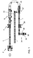
- the invention is comprised by a roller line, in which four stages are set up: a first stage of separating the trays, a second stage of overturning and emptying them, a third stage of inspecting for dirt and discrimination, and a fourth stage of stacking in uniform stacks.
- a lifting machine is connected which is in charge of raising the stack of trays to the level of the conveyor rollers where this stack is transported to a separator, which, by means of some claws driven hydraulically and vertically moveable, allow separating the lower tray from the stack by raising said stack; this tray will advance through the roller line to an overturning machine, in which a series of slanted conveyor belts and rotating supports receive and overturn the trays; the tray is overturned by the simple effect of gravity, dumping its contents into a waste collection bin, proceeding then and in the same manner to being overturned again to adopt its initial position.
- the empty tray is taken, on the aforementioned roller line to a machine that inspects for dirt by artificial vision, in which is attached a camera connected to hardware with programmed software which detects the possible adhered dirt as well as moisture, so that at the outlet of this machine the roller line diverges into two branches, one towards the belts corresponding to the trays that did not pass the required standards of cleanliness and a main branch that leads to a stacking machine, with a structure similar to the separating machine, but with the opposite function.
- a diverter is set up which sends each stack of trays towards different roller chains that take these stacks to the different warehouses.
- the machine In order to avoid collisions in raising and lowering the stacks, the machine includes two photoelectric barriers (10-10').
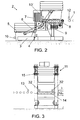
- the roller line (1) takes the stack to the separating machine (11), that shown in Figure 3 , comprised of a column in whose middle area there is a section of rollers (14) continuing the roller line (1) next to which there are two sensors (32) to control the position of the stack at the time of entering the machine.
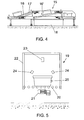
- This column incorporates some pneumatic claws (15) that are closed on the sides of the tray, holding it, and consequently the rest of the trays are stacked into it above, so that to separate it the machine is situated at the level of the second tray from the bottom, it closes on it, holding it, and proceeds to move said tray vertically, so that the lower tray is automatically separated, immediately connecting the drive of the roller section (14) that takes the separated tray alone towards the overturning machine (15), that shown in Figure 4 , which, through a pair of conveyor belts (16), open in their middle area and assisted on the ends by the respective overturning supports (17), allow in the first place to turn the tray over 180°, emptying its content into a bin (18), and subsequently returning to its initial position by means of the corresponding overturning.
- roller line section (1) with sufficient length as to permit accumulating several stacks of trays, including a photoelectric saturation sensor (12) and a pneumatic limit (13) that doses out and controls the entry of stacks to the separator.
- the outlet of the overturning machine is connected to a machine that inspects for dirt by artificial vision (19), in which there is a roller section (20), as a continuation of the roller line (1), a mechanism activated by means of a geared motor group (21).
- the machine includes a casing (22), open on both ends, in which a system of artificial vision is set up, which is comprised of a camera (23), a data processing unit, as well as LED projectors (24) that provide stable lighting conditions, so that through image-comparing software it detects the possible adhered dirt, as well as moisture, having provided that the flash of the camera (23) is done through a photoelectric sensor (25) that would detect the presence of the tray in the proper position to be photographed.
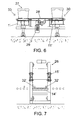
- roller line (1) diverges into two branches, a first branch (1') that takes the clean trays to a stacking machine (26), and a second branch (1") that by means of a diverter (27), that shown in the close up of Figure 6 , takes away the dirty trays for their proper cleaning.
- This diverter (27) is automatically activated upon detection of a dirty tray, so that through a photoelectric sensor (33) the drive of the rollers of the branch (1') stops and some belts (28) driven by a geared motor group (29) start up and move the tray to the branch (1"), a position that is detected through the corresponding photoelectric sensor (30), with this branch (1") including a photoelectric sensor (31) for the saturation of the line.
- the aforementioned stacking machine (26) will have a structure similar to that of the separator (11), with a column in the middle of which is a section of rollers (14'), two photoelectric sensors (32') for the control of the tray's position at the time it enters the machine, as well as some pneumatic claws (15') that close on the trays and move vertically, so that in this case, the claws (15) also move to the position immediately above the lower tray in order to proceed to open, depositing in that tray the set of trays that may have accumulated and stacked, in order to then move downwards a certain distance in order to hold the lower tray, and raise the entire stack allowing the entry of a new tray, and inserting in it the accumulated stack, repeating the process until reaching the programmed stack level.
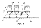
- a second diverter in charge of taking the checked and stacked trays to the two warehouses with rollers (35) and (36), for which a photoelectric sensor (37) to stop/start the motion of the corresponding rollers of the stopped line (1") after which some belts (38) connected to a geared motor group (41) start up which will divert crosswise the stacks of trays towards the corresponding roller warehouses (35) and (36), which will have photoelectric sensors (39-40) to stop the corresponding belts and activate the complementary rollers.
Landscapes
- Engineering & Computer Science (AREA)
- Mechanical Engineering (AREA)
- Sorting Of Articles (AREA)
- De-Stacking Of Articles (AREA)
- Attitude Control For Articles On Conveyors (AREA)
- Warehouses Or Storage Devices (AREA)
- Cleaning In General (AREA)
Claims (6)
- Einrichtung für die Bearbeitung von Tabletts, dadurch gekennzeichnet, dass diese eine Walzenreihe (1) besitzt, an deren Anfang sich eine Hebevorrichtung (2) befindet, die mit Mitteln für das Anheben eines Tablettstapels bis zu der Höhe von Laufrollen an einem Förderband der Walzenreihe (1) ausgestattet ist, einer Walzenreihe (1), die hinter einem Lagerbereich eine Trennmaschine (11) besitzt, die mit hydraulisch betriebenen Krallen (15) ausgestattet ist, die senkrecht, förmlich und dimensional auf geeignete Weise bewegt werden können, so dass die einzelnen Elemente des Stapels durch das Anheben des Stapels getrennt werden können. An dieses Gerät schließt sich eine Kippmaschine (15) an, die dann zum Einsatz kommt; in dieser befinden sich eine Reihe von geneigten Förderbändern (16, 16') und sich drehende Auflagen, von denen die Tabletts entgegen genommen und umgestürzt werden, wobei die Tabletts durch die Wirkung der Schwerkraft umkippen. Nach dieser Kippmaschine (15) ist eine Kontrollmaschine für die Verschmutzung mit einem künstlichen Visionssystem (19) angebracht. Diese ist mit einer, an eine Hardware mit einem Softwareprogramm angeschlossene Kamera ausgerüstet, von welcher eine an den Tabletts anhaftende Verschmutzung sowie Senf festgestellt werden kann. Am Ausgang dieser Maschine befinden sich ebenfalls zwei Verzweigungen, eine Verzweigung (1 "), auf der die Tabletts, welche die vorgeschriebenen Sauberkeitsstandards nicht erfüllt haben, umgeleitet werden und eine Hauptverzweigung (1'), die zu einer Stapelmaschine (26') führt, die einen der Trennmaschine (11) ähnlichen Aufbau, aber eine gegenteilige Funktion besitzt.
- Einrichtung für die Bearbeitung von Tabletts, gemäß dem ersten Patentanspruch, dadurch gekennzeichnet, dass sich am Ausgang der Stapelmaschine (26) ein Leitblech (34) mit einer Reihe von Bändern (38) befindet, die durch eine Triebwerkmotorgruppe (41) angetrieben werden, die durch den Einsatz verschiedener photoelektrischer Sensoren (37, 30, 40) den Tablettstapel ausrichten und ihn anschließend in verschiedene Walzenlager (35, 36) führen.
- Einrichtung für die Bearbeitung von Tabletts, gemäß dem ersten Patentanspruch, dadurch gekennzeichnet, dass sie mit einer Hebevorrichtung (2) ausgestattet ist, zu der ein niedriger Gestellrahmen (3) gehört, an dem sich ein photoelektrischer Sensor (4) befindet, der das Vorhandensein von Tabletts (5) feststellt. Die Hebevorrichtung ist mit zwei Armen (6) ausgestattet, durch die sich der Tablettstapel anheben lässt, und die durch eine Triebwerkmotorgruppe (7) angetrieben werden. Sie entladen den o. g. Stapel auf eine Reihe von Walzen, die durch eine Triebwerkmotorgruppe (9) angetrieben werden, die auf die Walzenreihe (1) ausgerichtet sind, wobei die Maschine mit zwei photoelektrischen Schranken (10-10') zur Bewegungseinschränkung der Arme (6) ausgestattet ist.
- Einrichtung für die Bearbeitung von Tabletts, gemäß dem ersten Patentanspruch, dadurch gekennzeichnet, dass eine Trennmaschine (11) vorhanden ist. Diese enthält eine Säule, in deren Mitte sich eine Walzenstrecke (14) befindet. An diese schließt sich eine Walzenreihe (1) an, neben der zwei photoelektrische Sensoren (32) für die Kontrolle des Stapels während dieser in die Maschine fährt, angebracht sind. In die Säule sind einige druckbetätigte Klauen angelassen (15), die mit Mitteln für das seitliche Aufheben des zweiten Tabletts von der Unterseite und für dessen Anheben ausgestattet sind.
- Einrichtung für die Bearbeitung von Tabletts, gemäß dem ersten Patentanspruch, dadurch gekennzeichnet, dass eine Kontrollmaschine für die Verschmutzung mit einem künstlichen Visionssystem (19) angebracht ist. In dieser befindet sich eine Walzenstrecke (20), an die sich eine Walzenreihe (1), ein von einer Triebwerkmotorgruppe (21) angetriebener Mechanismus, sowie ein beidseitig offenes Gehäuse (22) anschließt, in dem sich ein künstliches Visionssystem befindet, in dem eine Kamera (23), eine Datenverarbeitungseinheit sowie LED-Projektoren (24) zur Beleuchtung der Innenseite des Tabletts und ein photoelektrischer Sensoren (25) für das Ausrichten der Tabletts und das Auslösen der Kamera (23) untergebracht sind. Das Gerät enthält eine Software für das Feststellen von Verschmutzungen und Senf, mit der sich die, die Maschine verlassenden Tabletts unterschieden lassen.
- Einrichtung für die Bearbeitung von Tabletts, gemäß dem ersten Patentanspruch, dadurch gekennzeichnet, dass eine Einrichtung, die am Maschinenausgang für die Kontrolle von Verschmutzungen durch ein künstliches Visionssystem (19) sorgt, und ein Leitblech (27) vorhanden sind. Das Leitblech funktioniert gemäß der von der vorstehend genannten Maschine gesendeten Angaben und ist mit einem photoelektrischen Sensor (33) ausgerüstet, so dass die Walzen der Hauptverzweigung (1') angehalten und einige Bänder (28) aktiviert werden, die von einer Triebwerkmotorgruppe (29) angetrieben werden. Sie bringen das Tablett zu der Verzweigung (1 ") in eine Stellung, die durch den entsprechenden photoelektrischen Sensor (30) festgestellt wird. Diese Verzweigung (1") enthält ebenfalls einen photoelektrischen Sensor (31) für die Ausnutzung der Reihe.
Priority Applications (3)
| Application Number | Priority Date | Filing Date | Title |
|---|---|---|---|
| AT09380120T ATE555990T1 (de) | 2009-06-17 | 2009-06-17 | Anlage zur verarbeitung von schalen |
| ES09380120T ES2358716T1 (es) | 2009-06-17 | 2009-06-17 | Instalación para el tratamiento de cubetas. |
| EP09380120A EP2263944B1 (de) | 2009-06-17 | 2009-06-17 | Anlage zur Verarbeitung von Schalen |
Applications Claiming Priority (1)
| Application Number | Priority Date | Filing Date | Title |
|---|---|---|---|
| EP09380120A EP2263944B1 (de) | 2009-06-17 | 2009-06-17 | Anlage zur Verarbeitung von Schalen |
Publications (2)
| Publication Number | Publication Date |
|---|---|
| EP2263944A1 EP2263944A1 (de) | 2010-12-22 |
| EP2263944B1 true EP2263944B1 (de) | 2012-05-02 |
Family
ID=41127898
Family Applications (1)
| Application Number | Title | Priority Date | Filing Date |
|---|---|---|---|
| EP09380120A Not-in-force EP2263944B1 (de) | 2009-06-17 | 2009-06-17 | Anlage zur Verarbeitung von Schalen |
Country Status (3)
| Country | Link |
|---|---|
| EP (1) | EP2263944B1 (de) |
| AT (1) | ATE555990T1 (de) |
| ES (1) | ES2358716T1 (de) |
Cited By (1)
| Publication number | Priority date | Publication date | Assignee | Title |
|---|---|---|---|---|
| EP3962667A1 (de) * | 2019-05-02 | 2022-03-09 | Ocado Innovation Limited | Vorrichtung und verfahren für bilderzeugungsbehälter |
Families Citing this family (6)
| Publication number | Priority date | Publication date | Assignee | Title |
|---|---|---|---|---|
| DE102015106777B4 (de) * | 2015-04-30 | 2016-11-17 | Marianne Zippel | Verfahren sowie Inspektionssystem zur Ermittlung und Überprüfung des Oberflächenreinheitsgrades von industriell gereinigten Werkstücken oder Maschinenbauteilen |
| CN106124520B (zh) * | 2016-08-26 | 2018-08-28 | 武汉捷普瑞科技有限公司 | 一种全自动上下料和视觉检测的装置 |
| CA3091777A1 (en) * | 2019-09-02 | 2021-03-02 | Norman Schmidt | Pan cleaning system and improved cleaning stations |
| US12357145B2 (en) * | 2019-09-02 | 2025-07-15 | Food Machinery Engineering, LMTD | Pan cleaning machine and a method of operating the machine to clean pans |
| NL2027720B1 (en) * | 2021-03-08 | 2022-09-26 | One Tray S R L | An ultraviolet radiation cleaning system for baggage trays in an airport security environment |
| CN114308743B (zh) * | 2021-12-21 | 2024-04-05 | 重庆特斯联智慧科技股份有限公司 | 面向物流机器人的物品安检及装载系统 |
Family Cites Families (5)
| Publication number | Priority date | Publication date | Assignee | Title |
|---|---|---|---|---|
| GB710251A (en) * | 1950-05-18 | 1954-06-09 | Samuel John Young | Improvements in and relating to machines for emptying crates and like containers of bodies such as crown corks |
| GB900058A (en) * | 1959-11-19 | 1962-07-04 | Samuel John Young | Apparatus for inverting crates and like containers |
| DE1922490A1 (de) * | 1969-05-02 | 1970-11-19 | Hermann Kronseder | Automatische Inspektionsmaschine |
| DE4116183A1 (de) * | 1991-05-17 | 1992-11-19 | Kronseder Maschf Krones | Verfahren und abfuellanlage zum behandeln von mehrwegflaschen aus kunststoff |
| FR2746502B1 (fr) * | 1996-03-22 | 2004-07-09 | Kronenbourg Brasseries | Dispositif et procede de detection de debris de verre |
-
2009
- 2009-06-17 AT AT09380120T patent/ATE555990T1/de active
- 2009-06-17 ES ES09380120T patent/ES2358716T1/es active Pending
- 2009-06-17 EP EP09380120A patent/EP2263944B1/de not_active Not-in-force
Cited By (1)
| Publication number | Priority date | Publication date | Assignee | Title |
|---|---|---|---|---|
| EP3962667A1 (de) * | 2019-05-02 | 2022-03-09 | Ocado Innovation Limited | Vorrichtung und verfahren für bilderzeugungsbehälter |
Also Published As
| Publication number | Publication date |
|---|---|
| ES2358716T1 (es) | 2011-05-13 |
| ATE555990T1 (de) | 2012-05-15 |
| EP2263944A1 (de) | 2010-12-22 |
Similar Documents
| Publication | Publication Date | Title |
|---|---|---|
| EP2263944B1 (de) | Anlage zur Verarbeitung von Schalen | |
| EP2794439B1 (de) | Entpalettiersystem und entnahmeeinheit | |
| EP2125587B1 (de) | Vorrichtung und verfahren zur umsetzung von stückgut | |
| DE102009017211B3 (de) | Vorrichtung zur Rücknahme von Leergut, insbesondere Kunststoffflaschen und Metalldosen | |
| CN102781796B (zh) | 垃圾分类装置 | |
| CN207329025U (zh) | 一种全自动高速卸垛拆包机 | |
| US12006079B2 (en) | Stacking and packaging device | |
| CA2629264C (en) | System and method of sorting elongated wood boards for preparing rows | |
| CN108453062B (zh) | 基于速度匹配原理的包裹分拣方法 | |
| JPH02150221A (ja) | ひな鳥収容器の繰出し及び積重ね装置並びに繰出し及び積重ね方法 | |
| US10583998B2 (en) | Egg tray stacking machine | |
| US12428245B2 (en) | Device and conveyance system for packaging elongated items | |
| US20060219610A1 (en) | Tray stacking and buffer system and method of use | |
| KR101922513B1 (ko) | 도시락김 가공용 조미김 자동공급장치 | |
| CN110540032A (zh) | 送料机 | |
| JP2524927B2 (ja) | コンベヤ滞留防止装置 | |
| CN103979298A (zh) | Atm码垛机 | |
| CN212821173U (zh) | 一种铁块智能分拣系统 | |
| DE202008001683U1 (de) | Automatisierte Einlagerungsvorrichtung für ein Apothekerlager | |
| CN203855142U (zh) | Atm码垛机 | |
| CN115339662A (zh) | 一种冻干机进出料方法及自动进出料装置 | |
| US3161292A (en) | Device for elevating and sorting flexible sheets | |
| JPH089047Y2 (ja) | ゴミコンテナの受渡し装置 | |
| EP0864515B1 (de) | Vorrichtung zum Vereinzeln von aufgestapelten scheibenförmigen Datenträgern, insbesondere CD's | |
| JP6116203B2 (ja) | プリフォームコンテナ搬送システム、及び、同システムを構成するコンテナケース並びにコンテナケース装着部 |
Legal Events
| Date | Code | Title | Description |
|---|---|---|---|
| PUAI | Public reference made under article 153(3) epc to a published international application that has entered the european phase |
Free format text: ORIGINAL CODE: 0009012 |
|
| AK | Designated contracting states |
Kind code of ref document: A1 Designated state(s): AT BE BG CH CY CZ DE DK EE ES FI FR GB GR HR HU IE IS IT LI LT LU LV MC MK MT NL NO PL PT RO SE SI SK TR |
|
| AX | Request for extension of the european patent |
Extension state: AL BA RS |
|
| 17P | Request for examination filed |
Effective date: 20110325 |
|
| GRAP | Despatch of communication of intention to grant a patent |
Free format text: ORIGINAL CODE: EPIDOSNIGR1 |
|
| GRAS | Grant fee paid |
Free format text: ORIGINAL CODE: EPIDOSNIGR3 |
|
| GRAA | (expected) grant |
Free format text: ORIGINAL CODE: 0009210 |
|
| AK | Designated contracting states |
Kind code of ref document: B1 Designated state(s): AT BE BG CH CY CZ DE DK EE ES FI FR GB GR HR HU IE IS IT LI LT LU LV MC MK MT NL NO PL PT RO SE SI SK TR |
|
| REG | Reference to a national code |
Ref country code: GB Ref legal event code: FG4D |
|
| REG | Reference to a national code |
Ref country code: AT Ref legal event code: REF Ref document number: 555990 Country of ref document: AT Kind code of ref document: T Effective date: 20120515 Ref country code: CH Ref legal event code: EP |
|
| REG | Reference to a national code |
Ref country code: IE Ref legal event code: FG4D |
|
| REG | Reference to a national code |
Ref country code: DE Ref legal event code: R096 Ref document number: 602009006754 Country of ref document: DE Effective date: 20120621 |
|
| REG | Reference to a national code |
Ref country code: NL Ref legal event code: VDEP Effective date: 20120502 |
|
| REG | Reference to a national code |
Ref country code: LT Ref legal event code: MG4D Effective date: 20120502 |
|
| PG25 | Lapsed in a contracting state [announced via postgrant information from national office to epo] |
Ref country code: LT Free format text: LAPSE BECAUSE OF FAILURE TO SUBMIT A TRANSLATION OF THE DESCRIPTION OR TO PAY THE FEE WITHIN THE PRESCRIBED TIME-LIMIT Effective date: 20120502 Ref country code: CY Free format text: LAPSE BECAUSE OF FAILURE TO SUBMIT A TRANSLATION OF THE DESCRIPTION OR TO PAY THE FEE WITHIN THE PRESCRIBED TIME-LIMIT Effective date: 20120502 Ref country code: PL Free format text: LAPSE BECAUSE OF FAILURE TO SUBMIT A TRANSLATION OF THE DESCRIPTION OR TO PAY THE FEE WITHIN THE PRESCRIBED TIME-LIMIT Effective date: 20120502 Ref country code: SE Free format text: LAPSE BECAUSE OF FAILURE TO SUBMIT A TRANSLATION OF THE DESCRIPTION OR TO PAY THE FEE WITHIN THE PRESCRIBED TIME-LIMIT Effective date: 20120502 Ref country code: NO Free format text: LAPSE BECAUSE OF FAILURE TO SUBMIT A TRANSLATION OF THE DESCRIPTION OR TO PAY THE FEE WITHIN THE PRESCRIBED TIME-LIMIT Effective date: 20120802 Ref country code: IS Free format text: LAPSE BECAUSE OF FAILURE TO SUBMIT A TRANSLATION OF THE DESCRIPTION OR TO PAY THE FEE WITHIN THE PRESCRIBED TIME-LIMIT Effective date: 20120902 Ref country code: FI Free format text: LAPSE BECAUSE OF FAILURE TO SUBMIT A TRANSLATION OF THE DESCRIPTION OR TO PAY THE FEE WITHIN THE PRESCRIBED TIME-LIMIT Effective date: 20120502 |
|
| REG | Reference to a national code |
Ref country code: AT Ref legal event code: MK05 Ref document number: 555990 Country of ref document: AT Kind code of ref document: T Effective date: 20120502 |
|
| PG25 | Lapsed in a contracting state [announced via postgrant information from national office to epo] |
Ref country code: HR Free format text: LAPSE BECAUSE OF FAILURE TO SUBMIT A TRANSLATION OF THE DESCRIPTION OR TO PAY THE FEE WITHIN THE PRESCRIBED TIME-LIMIT Effective date: 20120502 Ref country code: PT Free format text: LAPSE BECAUSE OF FAILURE TO SUBMIT A TRANSLATION OF THE DESCRIPTION OR TO PAY THE FEE WITHIN THE PRESCRIBED TIME-LIMIT Effective date: 20120903 Ref country code: GR Free format text: LAPSE BECAUSE OF FAILURE TO SUBMIT A TRANSLATION OF THE DESCRIPTION OR TO PAY THE FEE WITHIN THE PRESCRIBED TIME-LIMIT Effective date: 20120803 Ref country code: LV Free format text: LAPSE BECAUSE OF FAILURE TO SUBMIT A TRANSLATION OF THE DESCRIPTION OR TO PAY THE FEE WITHIN THE PRESCRIBED TIME-LIMIT Effective date: 20120502 Ref country code: SI Free format text: LAPSE BECAUSE OF FAILURE TO SUBMIT A TRANSLATION OF THE DESCRIPTION OR TO PAY THE FEE WITHIN THE PRESCRIBED TIME-LIMIT Effective date: 20120502 |
|
| PG25 | Lapsed in a contracting state [announced via postgrant information from national office to epo] |
Ref country code: BE Free format text: LAPSE BECAUSE OF FAILURE TO SUBMIT A TRANSLATION OF THE DESCRIPTION OR TO PAY THE FEE WITHIN THE PRESCRIBED TIME-LIMIT Effective date: 20120502 |
|
| PG25 | Lapsed in a contracting state [announced via postgrant information from national office to epo] |
Ref country code: RO Free format text: LAPSE BECAUSE OF FAILURE TO SUBMIT A TRANSLATION OF THE DESCRIPTION OR TO PAY THE FEE WITHIN THE PRESCRIBED TIME-LIMIT Effective date: 20120502 Ref country code: EE Free format text: LAPSE BECAUSE OF FAILURE TO SUBMIT A TRANSLATION OF THE DESCRIPTION OR TO PAY THE FEE WITHIN THE PRESCRIBED TIME-LIMIT Effective date: 20120502 Ref country code: DK Free format text: LAPSE BECAUSE OF FAILURE TO SUBMIT A TRANSLATION OF THE DESCRIPTION OR TO PAY THE FEE WITHIN THE PRESCRIBED TIME-LIMIT Effective date: 20120502 Ref country code: NL Free format text: LAPSE BECAUSE OF FAILURE TO SUBMIT A TRANSLATION OF THE DESCRIPTION OR TO PAY THE FEE WITHIN THE PRESCRIBED TIME-LIMIT Effective date: 20120502 Ref country code: SK Free format text: LAPSE BECAUSE OF FAILURE TO SUBMIT A TRANSLATION OF THE DESCRIPTION OR TO PAY THE FEE WITHIN THE PRESCRIBED TIME-LIMIT Effective date: 20120502 Ref country code: AT Free format text: LAPSE BECAUSE OF FAILURE TO SUBMIT A TRANSLATION OF THE DESCRIPTION OR TO PAY THE FEE WITHIN THE PRESCRIBED TIME-LIMIT Effective date: 20120502 Ref country code: MC Free format text: LAPSE BECAUSE OF NON-PAYMENT OF DUE FEES Effective date: 20120630 Ref country code: CZ Free format text: LAPSE BECAUSE OF FAILURE TO SUBMIT A TRANSLATION OF THE DESCRIPTION OR TO PAY THE FEE WITHIN THE PRESCRIBED TIME-LIMIT Effective date: 20120502 |
|
| PG25 | Lapsed in a contracting state [announced via postgrant information from national office to epo] |
Ref country code: IT Free format text: LAPSE BECAUSE OF FAILURE TO SUBMIT A TRANSLATION OF THE DESCRIPTION OR TO PAY THE FEE WITHIN THE PRESCRIBED TIME-LIMIT Effective date: 20120502 Ref country code: MK Free format text: LAPSE BECAUSE OF FAILURE TO SUBMIT A TRANSLATION OF THE DESCRIPTION OR TO PAY THE FEE WITHIN THE PRESCRIBED TIME-LIMIT Effective date: 20120502 |
|
| PLBE | No opposition filed within time limit |
Free format text: ORIGINAL CODE: 0009261 |
|
| STAA | Information on the status of an ep patent application or granted ep patent |
Free format text: STATUS: NO OPPOSITION FILED WITHIN TIME LIMIT |
|
| REG | Reference to a national code |
Ref country code: IE Ref legal event code: MM4A |
|
| REG | Reference to a national code |
Ref country code: FR Ref legal event code: ST Effective date: 20130228 |
|
| 26N | No opposition filed |
Effective date: 20130205 |
|
| REG | Reference to a national code |
Ref country code: DE Ref legal event code: R119 Ref document number: 602009006754 Country of ref document: DE Effective date: 20130101 |
|
| PG25 | Lapsed in a contracting state [announced via postgrant information from national office to epo] |
Ref country code: ES Free format text: LAPSE BECAUSE OF FAILURE TO SUBMIT A TRANSLATION OF THE DESCRIPTION OR TO PAY THE FEE WITHIN THE PRESCRIBED TIME-LIMIT Effective date: 20120813 Ref country code: FR Free format text: LAPSE BECAUSE OF NON-PAYMENT OF DUE FEES Effective date: 20120702 Ref country code: DE Free format text: LAPSE BECAUSE OF NON-PAYMENT OF DUE FEES Effective date: 20130101 Ref country code: IE Free format text: LAPSE BECAUSE OF NON-PAYMENT OF DUE FEES Effective date: 20120617 |
|
| PG25 | Lapsed in a contracting state [announced via postgrant information from national office to epo] |
Ref country code: MT Free format text: LAPSE BECAUSE OF FAILURE TO SUBMIT A TRANSLATION OF THE DESCRIPTION OR TO PAY THE FEE WITHIN THE PRESCRIBED TIME-LIMIT Effective date: 20120502 Ref country code: BG Free format text: LAPSE BECAUSE OF FAILURE TO SUBMIT A TRANSLATION OF THE DESCRIPTION OR TO PAY THE FEE WITHIN THE PRESCRIBED TIME-LIMIT Effective date: 20120802 |
|
| REG | Reference to a national code |
Ref country code: CH Ref legal event code: PL |
|
| GBPC | Gb: european patent ceased through non-payment of renewal fee |
Effective date: 20130617 |
|
| PG25 | Lapsed in a contracting state [announced via postgrant information from national office to epo] |
Ref country code: TR Free format text: LAPSE BECAUSE OF FAILURE TO SUBMIT A TRANSLATION OF THE DESCRIPTION OR TO PAY THE FEE WITHIN THE PRESCRIBED TIME-LIMIT Effective date: 20120502 Ref country code: CH Free format text: LAPSE BECAUSE OF NON-PAYMENT OF DUE FEES Effective date: 20130630 Ref country code: LI Free format text: LAPSE BECAUSE OF NON-PAYMENT OF DUE FEES Effective date: 20130630 Ref country code: GB Free format text: LAPSE BECAUSE OF NON-PAYMENT OF DUE FEES Effective date: 20130617 |
|
| PG25 | Lapsed in a contracting state [announced via postgrant information from national office to epo] |
Ref country code: LU Free format text: LAPSE BECAUSE OF NON-PAYMENT OF DUE FEES Effective date: 20120617 |
|
| PG25 | Lapsed in a contracting state [announced via postgrant information from national office to epo] |
Ref country code: HU Free format text: LAPSE BECAUSE OF FAILURE TO SUBMIT A TRANSLATION OF THE DESCRIPTION OR TO PAY THE FEE WITHIN THE PRESCRIBED TIME-LIMIT Effective date: 20090617 |