EP2263238B1 - X-ray generator with polycapillary optic - Google Patents
X-ray generator with polycapillary optic Download PDFInfo
- Publication number
- EP2263238B1 EP2263238B1 EP09731087A EP09731087A EP2263238B1 EP 2263238 B1 EP2263238 B1 EP 2263238B1 EP 09731087 A EP09731087 A EP 09731087A EP 09731087 A EP09731087 A EP 09731087A EP 2263238 B1 EP2263238 B1 EP 2263238B1
- Authority
- EP
- European Patent Office
- Prior art keywords
- optic
- ray
- graded
- focusing
- source
- Prior art date
- Legal status (The legal status is an assumption and is not a legal conclusion. Google has not performed a legal analysis and makes no representation as to the accuracy of the status listed.)
- Active
Links
Images

Classifications
-
- G—PHYSICS
- G21—NUCLEAR PHYSICS; NUCLEAR ENGINEERING
- G21K—HANDLING OF PARTICLES OR IONISING RADIATION NOT OTHERWISE PROVIDED FOR; IRRADIATION DEVICES; GAMMA RAY OR X-RAY MICROSCOPES
- G21K1/00—Arrangements for handling particles or ionising radiation, e.g. focusing or moderating
- G21K1/06—Arrangements for handling particles or ionising radiation, e.g. focusing or moderating using diffraction, refraction or reflection, e.g. monochromators
-
- B—PERFORMING OPERATIONS; TRANSPORTING
- B82—NANOTECHNOLOGY
- B82Y—SPECIFIC USES OR APPLICATIONS OF NANOSTRUCTURES; MEASUREMENT OR ANALYSIS OF NANOSTRUCTURES; MANUFACTURE OR TREATMENT OF NANOSTRUCTURES
- B82Y10/00—Nanotechnology for information processing, storage or transmission, e.g. quantum computing or single electron logic
-
- G—PHYSICS
- G21—NUCLEAR PHYSICS; NUCLEAR ENGINEERING
- G21K—HANDLING OF PARTICLES OR IONISING RADIATION NOT OTHERWISE PROVIDED FOR; IRRADIATION DEVICES; GAMMA RAY OR X-RAY MICROSCOPES
- G21K2201/00—Arrangements for handling radiation or particles
- G21K2201/06—Arrangements for handling radiation or particles using diffractive, refractive or reflecting elements
- G21K2201/061—Arrangements for handling radiation or particles using diffractive, refractive or reflecting elements characterised by a multilayer structure
Definitions
- the present invention relates systems for generating and focusing x-ray radiation for analytical instruments including x-ray diffractometry, x-ray spectrometry or other x-ray analysis applications.
- X-rays are inherently difficult to direct.
- Different technologies have been employed to form x-ray beams. These include total reflection reflectors, optics based on total reflection principle such as capillary and polycapillary made of bundle of micro-sized waveguides, natural crystals, and man-made layered structures called multilayer optics.
- polychromatic radiation with energy spectrum over a relatively wide range may be desired.
- highly monochromitized radiation is desired.
- Optics are made with selected technologies to match with the beam requirements while maintain an acceptable cost.
- X-ray beam systems with excellent performance have been developed with microfocusing sources and variety of beam conditioning optics.
- Typical focal spot projection of these microfocusing sources is less than 100 micrometers and as small as 10 micrometers. Future development of source technology and optics technology may drive the brilliance even higher and spot size even smaller. Both stability of the spot size and spot position are critical for x-ray beams in analytical applications.
- microfocusing sources use much less energy therefore has a lower operation cost and cause less environment issues. Sealed tube microfocusing sources, not only offers good performance, but also offers good performance-cost ratio.
- Representative optics in a microfocusing sources based beam system include multilayer optics, crystal optics, total reflection mirrors, mono-capillary optics and polycapillary optics.
- Optics can be designed for redirecting x-rays in one direction only, i.e. so-called one-dimensional optics (1 D optics), or designed for redirecting x-rays in two perpendicular directions either through single interactions, two interactions or multiple interactions, i.e. so called two-dimensional optics (2D optics).
- one-dimensional optics 1 D optics
- 2D optics two-dimensional optics
- diffraction element should be a key part of the system.
- Multilayer optics naturally delivers monochromatic beams.
- the beam characteristics such as spatial definition, spectrum purity and intensity, can be optimized through various designs.
- Multilayer optics have been the major beam conditioning optics for x-ray scattering and diffraction.
- the probe beam is conditioned typically by a one-dimensional optic, meaning to redirect and form a beam in one direction only.
- optics include planar multilayer optic, parabolic multilayer optic, and elliptical multilayer optic. These optics have a profile of cylinder curve, i.e. the curvature in the direction perpendicular the beam propagation direction is straight line, and the curvature in the direction of beam propagation direction is a profile of either straight line (planar optic), or part of a parabola (collimating optics), or part of an ellipse (focusing optics). These optics are typically very efficient and are capable in delivering high flux beams.
- the probe beam has to be a two-dimensional beam, i.e. a "pencil-like" beam formed in two perpendicular directions.
- a beam can be formed by a two-dimensional optic.
- Multilayer two-dimensional optics are the major beam conditioning optics for the need of two-dimensional beam conditioning. These optics delivers beams with well defined spatial characteristics and good spectrum purity.
- Waveguide bundle optics represented by polycapillary optics
- waveguide bundle optics offer much large capture angle and therefore potentially much higher flux and brilliance.
- the issue with waveguide bundle optics is that the output, in nature, is x-rays with continuous spectrum and is not suitable for x-ray elastic scattering and x-ray diffraction.
- Such an optic could consist of two cylinder elliptical mirrors; each of the mirrors focuses x- rays in one of the two perpendicular directions and the two mirrors are in a so-called Kirkpatrick-Baez geometry, either in sequential or "side-by-side” arrangement as depicted in US patent 6,041,099 .
- Such an optic could also be part of an ellipsoid with multilayer coating inside, where a single reflection from the optic directing the x-rays in 2-dimensions.
- the first optic the polycapillary optic
- the polycapillary optic as a kinematical system, i.e. without energy input
- the entropy or the ordering represented by the spot size and divergence, of an isolated system without external energy input will at best be preserved and can not be reduced (or improved in terms of spot size and divergence).
- polycapillary lens comprises a plurality of tapered capillaries arranged such that both the diameter of the focal spot of an x-ray source and the angular divergence of x-rays are reduced" inevitably results in, in the best case, the same brilliance. Therefore, the performance of the system, in the best case, is equivalent to the performance of the direct coupling between the second optic and the source.
- the optic is a focusing optic
- the reflection angle gets smaller at first until the x-ray photons reach the point with largest diameter of the polycapillary optic, then gets larger with each consecutive reflection after passing the point with maximum diameter.
- photons reach the exit of the proposed optic in the patent 6,504,901 "bottle-shaped" optic where capillary diameter is smaller than at optic entrance, some portion of them will have incident angle larger than critical angle of external total reflection and will be lost, reducing optical system efficiency.
- US 6,333,966 B1 discloses an x-ray system comprising means for converting an electron beam to x-rays, a polycapillary x-ray lens having a "Point-To-Point Focus” and receiving said x-rays, and an energy filtering "Bent-Crystal" Bragg monochromator which receives the x-rays from the polycapillary x-ray lens and directs the x-rays to a sample.
- the present invention provides an improved x-ray system.
- the x-ray system includes a source of x-ray radiation configured to output divergent x-ray radiation, a waveguide bundle based optic, such as polycapillary optic, for collecting the x-ray radiation produced by the source at large capture angle, a focusing optic with a Bragg reflective surface for capturing the beam from the first optic and focusing the monochromatic x-ray radiation to a focal point.
- the waveguide bundle optic is designed in such a fashion that it provides a collimated beam.
- the focusing optic can be a Kirkpatrick-Baez side-by-side optic having multilayer Bragg x-ray reflecting surfaces that may be either laterally or laterally and depth graded.
- the focusing reflector can be parabolic cylinder surfaces.
- the focusing optic can also be a doubly curved optic, such as paraboloidal optics, having multilayer Bragg x-ray reflecting surface that may be either laterally or laterally and depth graded.
- the coupling between the waveguide bundle optic and the focusing optic is in such a way that the geometric focus of the focusing optic is at the virtual focus of the waveguide bundle optic or the other way around.
- the focusing optic preferably is a parabolic or paraboloidal optic having its focus at infinite.
- the x-ray system in accordance with this invention seeks to overcome the previously described design challenges of the prior art by providing a waveguide bundle based optical element closely coupled with an x-ray source which captures x-ray radiation from the source at a large capture angle and directs it to a further focusing element in a controlled beam size and desired ray configuration.
- collimated beam configurations can be readily provided.
- suitable additional focusing optics such as the previously mentioned Kirkpatrick-Baez multilayer parabolic optic or an paraboloidal optic, a beam with substantially high intensity can be acquired.
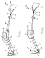
- Figure 1 illustrates an x-ray system having a waveguide bundle optic, such as polycapillary optic, and a Kirkpatrick-Baez side-by-side multilayer optic;
- a waveguide bundle optic such as polycapillary optic, and a Kirkpatrick-Baez side-by-side multilayer optic
- Figure 2 illustrates an x-ray system having a waveguide bundle optic (such as polycapillary optic) and a doubly curved multilayer optic; and
- Figure 3 illustrates a more detailed view of the waveguide bundle optic of Figures 1 and 2 .
- An x-ray analysis system 10a includes an x-ray source 12, a waveguide bundle optic (such as polycapillary optic) 14, a focusing optic 16a, an aperture 18, a sample 20, and an x-ray detector 22.
- the x-ray source 12 may be a laboratory source, such as a high brilliance rotating anode x-ray generator or a sealed tube microfocusing source.
- the x-ray source 12 generally includes an electron beam focusing system 24 and a target 26. Electron beam 28 is guided to the target 26 by the e-beam focusing system 24.
- the waveguide bundle optic 14 includes an input 30 and an output 32.
- the input 30 of the waveguide bundle optic is generally located about 3mm to 15mm, but not limited to, from the focus of the x-ray source 12. This distance between the input 30 of the waveguide bundle optic 14 and x-ray source 12 is better known as the focal distance.
- the waveguide bundle optic 14 guides the x-rays from its input to its output. The x-rays leaving the output 32 of the waveguide bundle optic are parallel.
- the focusing optic 16a in this embodiment is a Kirkpatrick-Baez side-by-side optic having multilayer Bragg x-ray reflecting surfaces 34 as described in U.S. Patent 6,041,099 .
- the Bragg x-ray reflecting surfaces 34 generally have graded-d spacing that is either lateral or lateral and depth graded.
- the x-rays 29 received by the Bragg x-ray reflecting surfaces 34 of the focusing optic 16a are then reflected by the Bragg x-ray reflecting surfaces 34 to a focal point 36.
- the surfaces of the mirrors preferably have a parabolic shape.
- the focusing optic 16a is positioned in such a way that the virtual focus of one of optics coincides with the real focus of other optic. This condition is critical and provides an effective acceptance by the focusing optic 16a of all the rays from the waveguide bundle optic 14.
- the reflected x-rays by the focusing optic 16a x-rays 31 are further defined by the aperture 18 in order to remove any unnecessary x-rays.
- the sample 20 is located adjacent to the focal point 36 and receives the reflected x-rays 31 shaped by the aperture 18.
- the sample 20 may be any sample, such as a biological sample, a polymer, or a crystallized protein, whose structure is the interest of study.
- the x-rays altered by the sample 20 are captured by an x-ray detector 22.
- the x-ray system 10b is similar to the x-ray system 10a in Figure 1 , however, the focusing optic 16b of the x-ray system 10b differs from that of the focusing optic 16a of the x-ray system 10a.
- the focusing optic 16b is a doubly curved optic, such as a paraboloidal optic, having multilayer Bragg x-ray reflecting surface.
- the multilayer Bragg reflecting surface 35 of the reflecting optic 16b has graded-d spacing that may be laterally graded or laterally and depth graded.
- the pre-conditioned x-rays 24 from the output 32 of the waveguide bundle optic, or polycapillary optic, 14 are reflected by the focusing optic 16b.
- the reflected x-rays 31 are then focused on a focal point 36.
- the sample 20 is located near the focal point 36 and is configured to receive the reflected x-rays 31.
- a detector 22 receives x- rays that have travelled through the sample 20 or are scattered or diffracted by the sample 20.
- the waveguide bundle optic 14 such as a polycapillary optic
- the source 12 emitting the x-rays 28 are separated from the input 30 of the waveguide bundle optic 14 by a distance f, known as the focal distance.
- the focal distance f is generally between about 3 millimeters to 15 millimeters but not limited to.
- the waveguide bundle optic 14 includes a plurality of hollow waveguides 40 which are bundled together and plastically shaped into configurations which allow efficient capture of divergent x-rays emerging from the x- ray source 12.
- the captured x-rays 28 are shaped by the waveguide bundle optic 14 into the collimated x-rays 29.
- Channel openings 42 located at the input 30 of the waveguide bundle optic 14 are pointing at the x-ray source 12.
- the diameters of the individual channel openings 42 at the input 30 of the waveguide bundle optic 14 preferably is smaller than the channel diameters at the output 32.
- the hollow waveguides, or capillaries, 40 are made of glass and have a diameter ranging from a few micrometers to sub-millimeters.
- the hollow capillaries may be made from carbon nanotubes with even smaller diameter of the channels.
Landscapes
- Engineering & Computer Science (AREA)
- Physics & Mathematics (AREA)
- Chemical & Material Sciences (AREA)
- Nanotechnology (AREA)
- Mathematical Physics (AREA)
- Theoretical Computer Science (AREA)
- Crystallography & Structural Chemistry (AREA)
- Spectroscopy & Molecular Physics (AREA)
- General Engineering & Computer Science (AREA)
- High Energy & Nuclear Physics (AREA)
- Analysing Materials By The Use Of Radiation (AREA)
Applications Claiming Priority (2)
| Application Number | Priority Date | Filing Date | Title |
|---|---|---|---|
| US4414808P | 2008-04-11 | 2008-04-11 | |
| PCT/US2009/040178 WO2009126868A1 (en) | 2008-04-11 | 2009-04-10 | X-ray generator with polycapillary optic |
Publications (2)
| Publication Number | Publication Date |
|---|---|
| EP2263238A1 EP2263238A1 (en) | 2010-12-22 |
| EP2263238B1 true EP2263238B1 (en) | 2012-06-20 |
Family
ID=40834348
Family Applications (1)
| Application Number | Title | Priority Date | Filing Date |
|---|---|---|---|
| EP09731087A Active EP2263238B1 (en) | 2008-04-11 | 2009-04-10 | X-ray generator with polycapillary optic |
Country Status (5)
| Country | Link |
|---|---|
| US (2) | US7933383B2 (enExample) |
| EP (1) | EP2263238B1 (enExample) |
| JP (1) | JP5531009B2 (enExample) |
| CA (1) | CA2720776C (enExample) |
| WO (1) | WO2009126868A1 (enExample) |
Families Citing this family (20)
| Publication number | Priority date | Publication date | Assignee | Title |
|---|---|---|---|---|
| WO2009126868A1 (en) * | 2008-04-11 | 2009-10-15 | Rigaku Innovative Technologies, Inc. | X-ray generator with polycapillary optic |
| FR2958858B1 (fr) * | 2010-04-15 | 2012-06-29 | Joel Kerjean | Dispositif de guidage de photons pour appareil de radiotherapie |
| JP2013528804A (ja) * | 2010-05-19 | 2013-07-11 | シルヴァー,エリック,エイチ | ハイブリッドx線光学機器および方法 |
| CN102543243B (zh) * | 2010-12-28 | 2016-07-13 | Ge医疗系统环球技术有限公司 | 集成毛细管式平行x射线聚焦透镜 |
| EP2740127B1 (en) * | 2011-08-06 | 2017-11-29 | Rigaku Innovative Technologies, Inc. | Nanotube based device for guiding x-ray photons and neutrons |
| US20130182827A1 (en) * | 2011-12-02 | 2013-07-18 | Canon Kabushiki Kaisha | X-ray waveguide and x-ray waveguide system |
| JP6016386B2 (ja) * | 2012-03-09 | 2016-10-26 | キヤノン株式会社 | X線光学装置 |
| JP5964705B2 (ja) * | 2012-09-14 | 2016-08-03 | 浜松ホトニクス株式会社 | ポリキャピラリレンズ |
| WO2014045273A1 (en) * | 2012-09-24 | 2014-03-27 | Convergent R.N.R Ltd | X-ray reflective lens arrangement |
| CN202905197U (zh) * | 2012-10-09 | 2013-04-24 | 北京师范大学 | 用于聚焦同步辐射光源的光学器件 |
| US20140161233A1 (en) * | 2012-12-06 | 2014-06-12 | Bruker Axs Gmbh | X-ray apparatus with deflectable electron beam |
| US9846132B2 (en) | 2013-10-21 | 2017-12-19 | Kla-Tencor Corporation | Small-angle scattering X-ray metrology systems and methods |
| US9885962B2 (en) * | 2013-10-28 | 2018-02-06 | Kla-Tencor Corporation | Methods and apparatus for measuring semiconductor device overlay using X-ray metrology |
| JP6069609B2 (ja) * | 2015-03-26 | 2017-02-01 | 株式会社リガク | 二重湾曲x線集光素子およびその構成体、二重湾曲x線分光素子およびその構成体の製造方法 |
| WO2017051890A1 (ja) * | 2015-09-25 | 2017-03-30 | 国立大学法人大阪大学 | X線顕微鏡 |
| US10677744B1 (en) * | 2016-06-03 | 2020-06-09 | U.S. Department Of Energy | Multi-cone x-ray imaging Bragg crystal spectrometer |
| KR102348995B1 (ko) * | 2016-07-15 | 2022-01-10 | 가부시키가이샤 리가쿠 | X선 검사 장치, x선 박막 검사 방법 및 로킹 커브 측정 방법 |
| JP6857400B2 (ja) * | 2018-03-01 | 2021-04-14 | 株式会社リガク | X線発生装置、及びx線分析装置 |
| JP2023539007A (ja) * | 2020-07-15 | 2023-09-13 | デンマークス、テクニスケ、ウニベルシテット | 実験室ベースの3D走査X線ラウエマイクロ回折システム及び方法(LAB3DμXRD) |
| CN119738425B (zh) * | 2024-12-13 | 2026-02-17 | 北京师范大学 | 一种组合镀膜毛细管x光单色聚焦透镜的分析系统及焦斑大小调节方法 |
Family Cites Families (27)
| Publication number | Priority date | Publication date | Assignee | Title |
|---|---|---|---|---|
| US5192869A (en) * | 1990-10-31 | 1993-03-09 | X-Ray Optical Systems, Inc. | Device for controlling beams of particles, X-ray and gamma quanta |
| US5497008A (en) * | 1990-10-31 | 1996-03-05 | X-Ray Optical Systems, Inc. | Use of a Kumakhov lens in analytic instruments |
| US5175755A (en) * | 1990-10-31 | 1992-12-29 | X-Ray Optical System, Inc. | Use of a kumakhov lens for x-ray lithography |
| EP0723272B1 (en) * | 1994-07-08 | 2001-04-25 | Muradin Abubekirovich Kumakhov | Method of guiding beams of neutral and charged particles and a device for implementing said method |
| US5570408A (en) * | 1995-02-28 | 1996-10-29 | X-Ray Optical Systems, Inc. | High intensity, small diameter x-ray beam, capillary optic system |
| US5604353A (en) * | 1995-06-12 | 1997-02-18 | X-Ray Optical Systems, Inc. | Multiple-channel, total-reflection optic with controllable divergence |
| US5745547A (en) * | 1995-08-04 | 1998-04-28 | X-Ray Optical Systems, Inc. | Multiple channel optic |
| US6041099A (en) * | 1998-02-19 | 2000-03-21 | Osmic, Inc. | Single corner kirkpatrick-baez beam conditioning optic assembly |
| GB9815968D0 (en) | 1998-07-23 | 1998-09-23 | Bede Scient Instr Ltd | X-ray focusing apparatus |
| US6333966B1 (en) * | 1998-08-18 | 2001-12-25 | Neil Charles Schoen | Laser accelerator femtosecond X-ray source |
| AU4161300A (en) * | 1999-04-01 | 2000-10-23 | Mamea Imaging Ab | Method and apparatus for simplified alignment in x-ray imaging |
| US6704389B1 (en) * | 1999-07-16 | 2004-03-09 | X-Ray Optical Systems, Inc. | Support device for a polycapillary optic |
| US6317483B1 (en) * | 1999-11-29 | 2001-11-13 | X-Ray Optical Systems, Inc. | Doubly curved optical device with graded atomic planes |
| US6697454B1 (en) * | 2000-06-29 | 2004-02-24 | X-Ray Optical Systems, Inc. | X-ray analytical techniques applied to combinatorial library screening |
| DE10112928C1 (de) * | 2001-03-12 | 2002-08-22 | Ifg Inst Fuer Geraetebau Gmbh | Kapillaroptisches Element bestehend aus Kanäle bildenden Kapillaren und Verfahren zu dessen Herstellung |
| RU2339974C2 (ru) * | 2001-06-19 | 2008-11-27 | Икс-Рэй Оптикал Системз, Инк. | Волновая дисперсивная рентгенофлуоресцентная система с использованием фокусирующей оптики для возбуждения и фокусирующий монохроматор для собирания |
| WO2003012797A1 (en) * | 2001-07-27 | 2003-02-13 | X-Ray Optical Systems, Inc. | Methods and devices for aligning and determining the focusing characteristics of x-ray optics |
| ATE476088T1 (de) * | 2001-12-04 | 2010-08-15 | X Ray Optical Sys Inc | Röntgenquelle mit verbesserter strahlstabilität und ihre anwendung in der analyse von strömenden flüssigkeiten |
| US6781060B2 (en) * | 2002-07-26 | 2004-08-24 | X-Ray Optical Systems Incorporated | Electrical connector, a cable sleeve, and a method for fabricating an electrical connection |
| US7382856B2 (en) * | 2001-12-04 | 2008-06-03 | X-Ray Optical Systems, Inc. | X-ray source assembly having enhanced output stability, and fluid stream analysis applications thereof |
| US7372880B2 (en) * | 2002-12-20 | 2008-05-13 | Alnair Labs Corporation | Optical pulse lasers |
| JP2007501503A (ja) * | 2003-08-04 | 2007-01-25 | エックス−レイ オプティカル システムズ インコーポレーテッド | 管電力調節および遠隔較正を使用して出力安定性が向上したx線源アセンブリ |
| US7023955B2 (en) * | 2003-08-12 | 2006-04-04 | X-Ray Optical System, Inc. | X-ray fluorescence system with apertured mask for analyzing patterned surfaces |
| WO2007019053A1 (en) * | 2005-08-04 | 2007-02-15 | X-Ray Optical Systems, Inc. | Monochromatic x-ray micro beam for trace element mapping |
| WO2008097345A2 (en) * | 2006-08-10 | 2008-08-14 | X-Ray Optical Systems, Inc. | Wide parallel beam diffraction imaging method and system |
| JP4860418B2 (ja) * | 2006-10-10 | 2012-01-25 | 株式会社リガク | X線光学系 |
| WO2009126868A1 (en) * | 2008-04-11 | 2009-10-15 | Rigaku Innovative Technologies, Inc. | X-ray generator with polycapillary optic |
-
2009
- 2009-04-10 WO PCT/US2009/040178 patent/WO2009126868A1/en not_active Ceased
- 2009-04-10 JP JP2011504197A patent/JP5531009B2/ja active Active
- 2009-04-10 EP EP09731087A patent/EP2263238B1/en active Active
- 2009-04-10 US US12/421,907 patent/US7933383B2/en active Active
- 2009-04-10 CA CA2720776A patent/CA2720776C/en active Active
-
2011
- 2011-03-18 US US13/051,708 patent/US20110280530A1/en not_active Abandoned
Also Published As
| Publication number | Publication date |
|---|---|
| US7933383B2 (en) | 2011-04-26 |
| JP2011516892A (ja) | 2011-05-26 |
| US20110280530A1 (en) | 2011-11-17 |
| JP5531009B2 (ja) | 2014-06-25 |
| CA2720776A1 (en) | 2009-10-15 |
| EP2263238A1 (en) | 2010-12-22 |
| WO2009126868A1 (en) | 2009-10-15 |
| CA2720776C (en) | 2013-07-02 |
| US20090279670A1 (en) | 2009-11-12 |
Similar Documents
| Publication | Publication Date | Title |
|---|---|---|
| EP2263238B1 (en) | X-ray generator with polycapillary optic | |
| CN1332399C (zh) | 用于x射线应用的光学装置 | |
| JP4860418B2 (ja) | X線光学系 | |
| JP3721305B2 (ja) | 単一隅カークパトリック・バエズのビーム調整光学素子組立体 | |
| JP4391019B2 (ja) | 並列カークパトリック・バエズ光学素子を備えた、x線方向付けシステム、x線反射システム及びx線光学素子 | |
| US20190011379A1 (en) | Method of performing x-ray spectroscopy and x-ray absorption spectrometer system | |
| US6249566B1 (en) | Apparatus for x-ray analysis | |
| EP1642304B1 (en) | Beam conditioning system | |
| CA2776726A1 (en) | Multiconfiguration x-ray optical system | |
| JP2007011403A (ja) | 徐々に変化する原子面を有する二重に湾曲した光学素子 | |
| JP2004506193A (ja) | X線測定および試験複合システム | |
| US11217357B2 (en) | X-ray mirror optics with multiple hyperboloidal/hyperbolic surface profiles | |
| US7280634B2 (en) | Beam conditioning system with sequential optic | |
| WO2001075488A1 (en) | Optical assembly for increasing the intensity of a formed x-ray beam | |
| CN120752520A (zh) | X射线聚焦与波长选择 | |
| EP2304739B9 (en) | High intensity x-ray beam system | |
| US7298822B2 (en) | X-ray optical element | |
| WO2025109498A2 (en) | X-ray focusing with wavelength selection systems for semiconductor metrology | |
| Poletto et al. | High-resolution monochromators for the utilization of the radiation from an EUV free-electron laser | |
| Jung et al. | Optimization of a spectromicroscopy beamline at BESSY II |
Legal Events
| Date | Code | Title | Description |
|---|---|---|---|
| PUAI | Public reference made under article 153(3) epc to a published international application that has entered the european phase |
Free format text: ORIGINAL CODE: 0009012 |
|
| 17P | Request for examination filed |
Effective date: 20101012 |
|
| AK | Designated contracting states |
Kind code of ref document: A1 Designated state(s): AT BE BG CH CY CZ DE DK EE ES FI FR GB GR HR HU IE IS IT LI LT LU LV MC MK MT NL NO PL PT RO SE SI SK TR |
|
| AX | Request for extension of the european patent |
Extension state: AL BA RS |
|
| 17Q | First examination report despatched |
Effective date: 20110322 |
|
| DAX | Request for extension of the european patent (deleted) | ||
| GRAP | Despatch of communication of intention to grant a patent |
Free format text: ORIGINAL CODE: EPIDOSNIGR1 |
|
| RAP1 | Party data changed (applicant data changed or rights of an application transferred) |
Owner name: RIGAKU INNOVATIVE TECHNOLOGIES, INC. |
|
| GRAS | Grant fee paid |
Free format text: ORIGINAL CODE: EPIDOSNIGR3 |
|
| GRAA | (expected) grant |
Free format text: ORIGINAL CODE: 0009210 |
|
| AK | Designated contracting states |
Kind code of ref document: B1 Designated state(s): AT BE BG CH CY CZ DE DK EE ES FI FR GB GR HR HU IE IS IT LI LT LU LV MC MK MT NL NO PL PT RO SE SI SK TR |
|
| REG | Reference to a national code |
Ref country code: GB Ref legal event code: FG4D |
|
| REG | Reference to a national code |
Ref country code: CH Ref legal event code: EP |
|
| REG | Reference to a national code |
Ref country code: AT Ref legal event code: REF Ref document number: 563453 Country of ref document: AT Kind code of ref document: T Effective date: 20120715 |
|
| REG | Reference to a national code |
Ref country code: IE Ref legal event code: FG4D |
|
| REG | Reference to a national code |
Ref country code: DE Ref legal event code: R096 Ref document number: 602009007745 Country of ref document: DE Effective date: 20120816 |
|
| REG | Reference to a national code |
Ref country code: NL Ref legal event code: T3 |
|
| PG25 | Lapsed in a contracting state [announced via postgrant information from national office to epo] |
Ref country code: NO Free format text: LAPSE BECAUSE OF FAILURE TO SUBMIT A TRANSLATION OF THE DESCRIPTION OR TO PAY THE FEE WITHIN THE PRESCRIBED TIME-LIMIT Effective date: 20120920 Ref country code: SE Free format text: LAPSE BECAUSE OF FAILURE TO SUBMIT A TRANSLATION OF THE DESCRIPTION OR TO PAY THE FEE WITHIN THE PRESCRIBED TIME-LIMIT Effective date: 20120620 Ref country code: LT Free format text: LAPSE BECAUSE OF FAILURE TO SUBMIT A TRANSLATION OF THE DESCRIPTION OR TO PAY THE FEE WITHIN THE PRESCRIBED TIME-LIMIT Effective date: 20120620 Ref country code: FI Free format text: LAPSE BECAUSE OF FAILURE TO SUBMIT A TRANSLATION OF THE DESCRIPTION OR TO PAY THE FEE WITHIN THE PRESCRIBED TIME-LIMIT Effective date: 20120620 |
|
| REG | Reference to a national code |
Ref country code: CH Ref legal event code: NV Representative=s name: TROESCH SCHEIDEGGER WERNER AG |
|
| REG | Reference to a national code |
Ref country code: LT Ref legal event code: MG4D Effective date: 20120620 |
|
| PG25 | Lapsed in a contracting state [announced via postgrant information from national office to epo] |
Ref country code: LV Free format text: LAPSE BECAUSE OF FAILURE TO SUBMIT A TRANSLATION OF THE DESCRIPTION OR TO PAY THE FEE WITHIN THE PRESCRIBED TIME-LIMIT Effective date: 20120620 Ref country code: SI Free format text: LAPSE BECAUSE OF FAILURE TO SUBMIT A TRANSLATION OF THE DESCRIPTION OR TO PAY THE FEE WITHIN THE PRESCRIBED TIME-LIMIT Effective date: 20120620 Ref country code: GR Free format text: LAPSE BECAUSE OF FAILURE TO SUBMIT A TRANSLATION OF THE DESCRIPTION OR TO PAY THE FEE WITHIN THE PRESCRIBED TIME-LIMIT Effective date: 20120921 Ref country code: HR Free format text: LAPSE BECAUSE OF FAILURE TO SUBMIT A TRANSLATION OF THE DESCRIPTION OR TO PAY THE FEE WITHIN THE PRESCRIBED TIME-LIMIT Effective date: 20120620 |
|
| PG25 | Lapsed in a contracting state [announced via postgrant information from national office to epo] |
Ref country code: IS Free format text: LAPSE BECAUSE OF FAILURE TO SUBMIT A TRANSLATION OF THE DESCRIPTION OR TO PAY THE FEE WITHIN THE PRESCRIBED TIME-LIMIT Effective date: 20121020 Ref country code: BE Free format text: LAPSE BECAUSE OF FAILURE TO SUBMIT A TRANSLATION OF THE DESCRIPTION OR TO PAY THE FEE WITHIN THE PRESCRIBED TIME-LIMIT Effective date: 20120620 Ref country code: CY Free format text: LAPSE BECAUSE OF FAILURE TO SUBMIT A TRANSLATION OF THE DESCRIPTION OR TO PAY THE FEE WITHIN THE PRESCRIBED TIME-LIMIT Effective date: 20120620 Ref country code: EE Free format text: LAPSE BECAUSE OF FAILURE TO SUBMIT A TRANSLATION OF THE DESCRIPTION OR TO PAY THE FEE WITHIN THE PRESCRIBED TIME-LIMIT Effective date: 20120620 Ref country code: SK Free format text: LAPSE BECAUSE OF FAILURE TO SUBMIT A TRANSLATION OF THE DESCRIPTION OR TO PAY THE FEE WITHIN THE PRESCRIBED TIME-LIMIT Effective date: 20120620 Ref country code: RO Free format text: LAPSE BECAUSE OF FAILURE TO SUBMIT A TRANSLATION OF THE DESCRIPTION OR TO PAY THE FEE WITHIN THE PRESCRIBED TIME-LIMIT Effective date: 20120620 |
|
| PG25 | Lapsed in a contracting state [announced via postgrant information from national office to epo] |
Ref country code: PL Free format text: LAPSE BECAUSE OF FAILURE TO SUBMIT A TRANSLATION OF THE DESCRIPTION OR TO PAY THE FEE WITHIN THE PRESCRIBED TIME-LIMIT Effective date: 20120620 Ref country code: PT Free format text: LAPSE BECAUSE OF FAILURE TO SUBMIT A TRANSLATION OF THE DESCRIPTION OR TO PAY THE FEE WITHIN THE PRESCRIBED TIME-LIMIT Effective date: 20121022 Ref country code: IT Free format text: LAPSE BECAUSE OF FAILURE TO SUBMIT A TRANSLATION OF THE DESCRIPTION OR TO PAY THE FEE WITHIN THE PRESCRIBED TIME-LIMIT Effective date: 20120620 |
|
| PLBE | No opposition filed within time limit |
Free format text: ORIGINAL CODE: 0009261 |
|
| STAA | Information on the status of an ep patent application or granted ep patent |
Free format text: STATUS: NO OPPOSITION FILED WITHIN TIME LIMIT |
|
| PG25 | Lapsed in a contracting state [announced via postgrant information from national office to epo] |
Ref country code: DK Free format text: LAPSE BECAUSE OF FAILURE TO SUBMIT A TRANSLATION OF THE DESCRIPTION OR TO PAY THE FEE WITHIN THE PRESCRIBED TIME-LIMIT Effective date: 20120620 Ref country code: ES Free format text: LAPSE BECAUSE OF FAILURE TO SUBMIT A TRANSLATION OF THE DESCRIPTION OR TO PAY THE FEE WITHIN THE PRESCRIBED TIME-LIMIT Effective date: 20121001 |
|
| 26N | No opposition filed |
Effective date: 20130321 |
|
| REG | Reference to a national code |
Ref country code: DE Ref legal event code: R097 Ref document number: 602009007745 Country of ref document: DE Effective date: 20130321 |
|
| PG25 | Lapsed in a contracting state [announced via postgrant information from national office to epo] |
Ref country code: BG Free format text: LAPSE BECAUSE OF FAILURE TO SUBMIT A TRANSLATION OF THE DESCRIPTION OR TO PAY THE FEE WITHIN THE PRESCRIBED TIME-LIMIT Effective date: 20120920 |
|
| PG25 | Lapsed in a contracting state [announced via postgrant information from national office to epo] |
Ref country code: MC Free format text: LAPSE BECAUSE OF FAILURE TO SUBMIT A TRANSLATION OF THE DESCRIPTION OR TO PAY THE FEE WITHIN THE PRESCRIBED TIME-LIMIT Effective date: 20120620 |
|
| REG | Reference to a national code |
Ref country code: IE Ref legal event code: MM4A |
|
| PG25 | Lapsed in a contracting state [announced via postgrant information from national office to epo] |
Ref country code: IE Free format text: LAPSE BECAUSE OF NON-PAYMENT OF DUE FEES Effective date: 20130410 |
|
| PG25 | Lapsed in a contracting state [announced via postgrant information from national office to epo] |
Ref country code: MT Free format text: LAPSE BECAUSE OF FAILURE TO SUBMIT A TRANSLATION OF THE DESCRIPTION OR TO PAY THE FEE WITHIN THE PRESCRIBED TIME-LIMIT Effective date: 20120620 |
|
| PG25 | Lapsed in a contracting state [announced via postgrant information from national office to epo] |
Ref country code: TR Free format text: LAPSE BECAUSE OF FAILURE TO SUBMIT A TRANSLATION OF THE DESCRIPTION OR TO PAY THE FEE WITHIN THE PRESCRIBED TIME-LIMIT Effective date: 20120620 |
|
| PG25 | Lapsed in a contracting state [announced via postgrant information from national office to epo] |
Ref country code: LU Free format text: LAPSE BECAUSE OF NON-PAYMENT OF DUE FEES Effective date: 20130410 Ref country code: MK Free format text: LAPSE BECAUSE OF FAILURE TO SUBMIT A TRANSLATION OF THE DESCRIPTION OR TO PAY THE FEE WITHIN THE PRESCRIBED TIME-LIMIT Effective date: 20120620 Ref country code: HU Free format text: LAPSE BECAUSE OF FAILURE TO SUBMIT A TRANSLATION OF THE DESCRIPTION OR TO PAY THE FEE WITHIN THE PRESCRIBED TIME-LIMIT; INVALID AB INITIO Effective date: 20090410 |
|
| REG | Reference to a national code |
Ref country code: FR Ref legal event code: PLFP Year of fee payment: 8 |
|
| REG | Reference to a national code |
Ref country code: FR Ref legal event code: PLFP Year of fee payment: 9 |
|
| REG | Reference to a national code |
Ref country code: FR Ref legal event code: PLFP Year of fee payment: 10 |
|
| P01 | Opt-out of the competence of the unified patent court (upc) registered |
Effective date: 20230526 |
|
| PGFP | Annual fee paid to national office [announced via postgrant information from national office to epo] |
Ref country code: DE Payment date: 20250317 Year of fee payment: 17 |
|
| PGFP | Annual fee paid to national office [announced via postgrant information from national office to epo] |
Ref country code: CH Payment date: 20250501 Year of fee payment: 17 |
|
| PGFP | Annual fee paid to national office [announced via postgrant information from national office to epo] |
Ref country code: AT Payment date: 20250326 Year of fee payment: 17 |
|
| PGFP | Annual fee paid to national office [announced via postgrant information from national office to epo] |
Ref country code: GB Payment date: 20260320 Year of fee payment: 18 |
|
| PGFP | Annual fee paid to national office [announced via postgrant information from national office to epo] |
Ref country code: NL Payment date: 20260323 Year of fee payment: 18 |
|
| PGFP | Annual fee paid to national office [announced via postgrant information from national office to epo] |
Ref country code: FR Payment date: 20260317 Year of fee payment: 18 |
|
| PGFP | Annual fee paid to national office [announced via postgrant information from national office to epo] |
Ref country code: CZ Payment date: 20260326 Year of fee payment: 18 |