EP2261191A1 - Piezoelectric ceramic, and piezoelectric elementing using the same - Google Patents
Piezoelectric ceramic, and piezoelectric elementing using the same Download PDFInfo
- Publication number
- EP2261191A1 EP2261191A1 EP09728523A EP09728523A EP2261191A1 EP 2261191 A1 EP2261191 A1 EP 2261191A1 EP 09728523 A EP09728523 A EP 09728523A EP 09728523 A EP09728523 A EP 09728523A EP 2261191 A1 EP2261191 A1 EP 2261191A1
- Authority
- EP
- European Patent Office
- Prior art keywords
- coo
- piezoelectric
- mass
- parts
- dynamic
- Prior art date
- Legal status (The legal status is an assumption and is not a legal conclusion. Google has not performed a legal analysis and makes no representation as to the accuracy of the status listed.)
- Granted
Links
Images


Classifications
-
- C—CHEMISTRY; METALLURGY
- C04—CEMENTS; CONCRETE; ARTIFICIAL STONE; CERAMICS; REFRACTORIES
- C04B—LIME, MAGNESIA; SLAG; CEMENTS; COMPOSITIONS THEREOF, e.g. MORTARS, CONCRETE OR LIKE BUILDING MATERIALS; ARTIFICIAL STONE; CERAMICS; REFRACTORIES; TREATMENT OF NATURAL STONE
- C04B35/00—Shaped ceramic products characterised by their composition; Ceramics compositions; Processing powders of inorganic compounds preparatory to the manufacturing of ceramic products
- C04B35/01—Shaped ceramic products characterised by their composition; Ceramics compositions; Processing powders of inorganic compounds preparatory to the manufacturing of ceramic products based on oxide ceramics
- C04B35/46—Shaped ceramic products characterised by their composition; Ceramics compositions; Processing powders of inorganic compounds preparatory to the manufacturing of ceramic products based on oxide ceramics based on titanium oxides or titanates
- C04B35/462—Shaped ceramic products characterised by their composition; Ceramics compositions; Processing powders of inorganic compounds preparatory to the manufacturing of ceramic products based on oxide ceramics based on titanium oxides or titanates based on titanates
- C04B35/475—Shaped ceramic products characterised by their composition; Ceramics compositions; Processing powders of inorganic compounds preparatory to the manufacturing of ceramic products based on oxide ceramics based on titanium oxides or titanates based on titanates based on bismuth titanates
-
- C—CHEMISTRY; METALLURGY
- C04—CEMENTS; CONCRETE; ARTIFICIAL STONE; CERAMICS; REFRACTORIES
- C04B—LIME, MAGNESIA; SLAG; CEMENTS; COMPOSITIONS THEREOF, e.g. MORTARS, CONCRETE OR LIKE BUILDING MATERIALS; ARTIFICIAL STONE; CERAMICS; REFRACTORIES; TREATMENT OF NATURAL STONE
- C04B35/00—Shaped ceramic products characterised by their composition; Ceramics compositions; Processing powders of inorganic compounds preparatory to the manufacturing of ceramic products
- C04B35/622—Forming processes; Processing powders of inorganic compounds preparatory to the manufacturing of ceramic products
- C04B35/64—Burning or sintering processes
-
- H—ELECTRICITY
- H10—SEMICONDUCTOR DEVICES; ELECTRIC SOLID-STATE DEVICES NOT OTHERWISE PROVIDED FOR
- H10N—ELECTRIC SOLID-STATE DEVICES NOT OTHERWISE PROVIDED FOR
- H10N30/00—Piezoelectric or electrostrictive devices
- H10N30/80—Constructional details
- H10N30/85—Piezoelectric or electrostrictive active materials
- H10N30/853—Ceramic compositions
- H10N30/8561—Bismuth based oxides
-
- C—CHEMISTRY; METALLURGY
- C04—CEMENTS; CONCRETE; ARTIFICIAL STONE; CERAMICS; REFRACTORIES
- C04B—LIME, MAGNESIA; SLAG; CEMENTS; COMPOSITIONS THEREOF, e.g. MORTARS, CONCRETE OR LIKE BUILDING MATERIALS; ARTIFICIAL STONE; CERAMICS; REFRACTORIES; TREATMENT OF NATURAL STONE
- C04B2235/00—Aspects relating to ceramic starting mixtures or sintered ceramic products
- C04B2235/02—Composition of constituents of the starting material or of secondary phases of the final product
- C04B2235/30—Constituents and secondary phases not being of a fibrous nature
- C04B2235/32—Metal oxides, mixed metal oxides, or oxide-forming salts thereof, e.g. carbonates, nitrates, (oxy)hydroxides, chlorides
- C04B2235/3201—Alkali metal oxides or oxide-forming salts thereof
- C04B2235/3203—Lithium oxide or oxide-forming salts thereof
-
- C—CHEMISTRY; METALLURGY
- C04—CEMENTS; CONCRETE; ARTIFICIAL STONE; CERAMICS; REFRACTORIES
- C04B—LIME, MAGNESIA; SLAG; CEMENTS; COMPOSITIONS THEREOF, e.g. MORTARS, CONCRETE OR LIKE BUILDING MATERIALS; ARTIFICIAL STONE; CERAMICS; REFRACTORIES; TREATMENT OF NATURAL STONE
- C04B2235/00—Aspects relating to ceramic starting mixtures or sintered ceramic products
- C04B2235/02—Composition of constituents of the starting material or of secondary phases of the final product
- C04B2235/30—Constituents and secondary phases not being of a fibrous nature
- C04B2235/32—Metal oxides, mixed metal oxides, or oxide-forming salts thereof, e.g. carbonates, nitrates, (oxy)hydroxides, chlorides
- C04B2235/3205—Alkaline earth oxides or oxide forming salts thereof, e.g. beryllium oxide
- C04B2235/3208—Calcium oxide or oxide-forming salts thereof, e.g. lime
-
- C—CHEMISTRY; METALLURGY
- C04—CEMENTS; CONCRETE; ARTIFICIAL STONE; CERAMICS; REFRACTORIES
- C04B—LIME, MAGNESIA; SLAG; CEMENTS; COMPOSITIONS THEREOF, e.g. MORTARS, CONCRETE OR LIKE BUILDING MATERIALS; ARTIFICIAL STONE; CERAMICS; REFRACTORIES; TREATMENT OF NATURAL STONE
- C04B2235/00—Aspects relating to ceramic starting mixtures or sintered ceramic products
- C04B2235/02—Composition of constituents of the starting material or of secondary phases of the final product
- C04B2235/30—Constituents and secondary phases not being of a fibrous nature
- C04B2235/32—Metal oxides, mixed metal oxides, or oxide-forming salts thereof, e.g. carbonates, nitrates, (oxy)hydroxides, chlorides
- C04B2235/3205—Alkaline earth oxides or oxide forming salts thereof, e.g. beryllium oxide
- C04B2235/3213—Strontium oxides or oxide-forming salts thereof
-
- C—CHEMISTRY; METALLURGY
- C04—CEMENTS; CONCRETE; ARTIFICIAL STONE; CERAMICS; REFRACTORIES
- C04B—LIME, MAGNESIA; SLAG; CEMENTS; COMPOSITIONS THEREOF, e.g. MORTARS, CONCRETE OR LIKE BUILDING MATERIALS; ARTIFICIAL STONE; CERAMICS; REFRACTORIES; TREATMENT OF NATURAL STONE
- C04B2235/00—Aspects relating to ceramic starting mixtures or sintered ceramic products
- C04B2235/02—Composition of constituents of the starting material or of secondary phases of the final product
- C04B2235/30—Constituents and secondary phases not being of a fibrous nature
- C04B2235/32—Metal oxides, mixed metal oxides, or oxide-forming salts thereof, e.g. carbonates, nitrates, (oxy)hydroxides, chlorides
- C04B2235/3205—Alkaline earth oxides or oxide forming salts thereof, e.g. beryllium oxide
- C04B2235/3215—Barium oxides or oxide-forming salts thereof
-
- C—CHEMISTRY; METALLURGY
- C04—CEMENTS; CONCRETE; ARTIFICIAL STONE; CERAMICS; REFRACTORIES
- C04B—LIME, MAGNESIA; SLAG; CEMENTS; COMPOSITIONS THEREOF, e.g. MORTARS, CONCRETE OR LIKE BUILDING MATERIALS; ARTIFICIAL STONE; CERAMICS; REFRACTORIES; TREATMENT OF NATURAL STONE
- C04B2235/00—Aspects relating to ceramic starting mixtures or sintered ceramic products
- C04B2235/02—Composition of constituents of the starting material or of secondary phases of the final product
- C04B2235/30—Constituents and secondary phases not being of a fibrous nature
- C04B2235/32—Metal oxides, mixed metal oxides, or oxide-forming salts thereof, e.g. carbonates, nitrates, (oxy)hydroxides, chlorides
- C04B2235/3224—Rare earth oxide or oxide forming salts thereof, e.g. scandium oxide
- C04B2235/3227—Lanthanum oxide or oxide-forming salts thereof
-
- C—CHEMISTRY; METALLURGY
- C04—CEMENTS; CONCRETE; ARTIFICIAL STONE; CERAMICS; REFRACTORIES
- C04B—LIME, MAGNESIA; SLAG; CEMENTS; COMPOSITIONS THEREOF, e.g. MORTARS, CONCRETE OR LIKE BUILDING MATERIALS; ARTIFICIAL STONE; CERAMICS; REFRACTORIES; TREATMENT OF NATURAL STONE
- C04B2235/00—Aspects relating to ceramic starting mixtures or sintered ceramic products
- C04B2235/02—Composition of constituents of the starting material or of secondary phases of the final product
- C04B2235/30—Constituents and secondary phases not being of a fibrous nature
- C04B2235/32—Metal oxides, mixed metal oxides, or oxide-forming salts thereof, e.g. carbonates, nitrates, (oxy)hydroxides, chlorides
- C04B2235/3224—Rare earth oxide or oxide forming salts thereof, e.g. scandium oxide
- C04B2235/3229—Cerium oxides or oxide-forming salts thereof
-
- C—CHEMISTRY; METALLURGY
- C04—CEMENTS; CONCRETE; ARTIFICIAL STONE; CERAMICS; REFRACTORIES
- C04B—LIME, MAGNESIA; SLAG; CEMENTS; COMPOSITIONS THEREOF, e.g. MORTARS, CONCRETE OR LIKE BUILDING MATERIALS; ARTIFICIAL STONE; CERAMICS; REFRACTORIES; TREATMENT OF NATURAL STONE
- C04B2235/00—Aspects relating to ceramic starting mixtures or sintered ceramic products
- C04B2235/02—Composition of constituents of the starting material or of secondary phases of the final product
- C04B2235/30—Constituents and secondary phases not being of a fibrous nature
- C04B2235/32—Metal oxides, mixed metal oxides, or oxide-forming salts thereof, e.g. carbonates, nitrates, (oxy)hydroxides, chlorides
- C04B2235/3231—Refractory metal oxides, their mixed metal oxides, or oxide-forming salts thereof
- C04B2235/3232—Titanium oxides or titanates, e.g. rutile or anatase
- C04B2235/3234—Titanates, not containing zirconia
- C04B2235/3236—Alkaline earth titanates
-
- C—CHEMISTRY; METALLURGY
- C04—CEMENTS; CONCRETE; ARTIFICIAL STONE; CERAMICS; REFRACTORIES
- C04B—LIME, MAGNESIA; SLAG; CEMENTS; COMPOSITIONS THEREOF, e.g. MORTARS, CONCRETE OR LIKE BUILDING MATERIALS; ARTIFICIAL STONE; CERAMICS; REFRACTORIES; TREATMENT OF NATURAL STONE
- C04B2235/00—Aspects relating to ceramic starting mixtures or sintered ceramic products
- C04B2235/02—Composition of constituents of the starting material or of secondary phases of the final product
- C04B2235/30—Constituents and secondary phases not being of a fibrous nature
- C04B2235/32—Metal oxides, mixed metal oxides, or oxide-forming salts thereof, e.g. carbonates, nitrates, (oxy)hydroxides, chlorides
- C04B2235/3231—Refractory metal oxides, their mixed metal oxides, or oxide-forming salts thereof
- C04B2235/3251—Niobium oxides, niobates, tantalum oxides, tantalates, or oxide-forming salts thereof
- C04B2235/3255—Niobates or tantalates, e.g. silver niobate
-
- C—CHEMISTRY; METALLURGY
- C04—CEMENTS; CONCRETE; ARTIFICIAL STONE; CERAMICS; REFRACTORIES
- C04B—LIME, MAGNESIA; SLAG; CEMENTS; COMPOSITIONS THEREOF, e.g. MORTARS, CONCRETE OR LIKE BUILDING MATERIALS; ARTIFICIAL STONE; CERAMICS; REFRACTORIES; TREATMENT OF NATURAL STONE
- C04B2235/00—Aspects relating to ceramic starting mixtures or sintered ceramic products
- C04B2235/02—Composition of constituents of the starting material or of secondary phases of the final product
- C04B2235/30—Constituents and secondary phases not being of a fibrous nature
- C04B2235/32—Metal oxides, mixed metal oxides, or oxide-forming salts thereof, e.g. carbonates, nitrates, (oxy)hydroxides, chlorides
- C04B2235/3262—Manganese oxides, manganates, rhenium oxides or oxide-forming salts thereof, e.g. MnO
- C04B2235/3267—MnO2
-
- C—CHEMISTRY; METALLURGY
- C04—CEMENTS; CONCRETE; ARTIFICIAL STONE; CERAMICS; REFRACTORIES
- C04B—LIME, MAGNESIA; SLAG; CEMENTS; COMPOSITIONS THEREOF, e.g. MORTARS, CONCRETE OR LIKE BUILDING MATERIALS; ARTIFICIAL STONE; CERAMICS; REFRACTORIES; TREATMENT OF NATURAL STONE
- C04B2235/00—Aspects relating to ceramic starting mixtures or sintered ceramic products
- C04B2235/02—Composition of constituents of the starting material or of secondary phases of the final product
- C04B2235/30—Constituents and secondary phases not being of a fibrous nature
- C04B2235/32—Metal oxides, mixed metal oxides, or oxide-forming salts thereof, e.g. carbonates, nitrates, (oxy)hydroxides, chlorides
- C04B2235/327—Iron group oxides, their mixed metal oxides, or oxide-forming salts thereof
- C04B2235/3272—Iron oxides or oxide forming salts thereof, e.g. hematite, magnetite
- C04B2235/3274—Ferrites
-
- C—CHEMISTRY; METALLURGY
- C04—CEMENTS; CONCRETE; ARTIFICIAL STONE; CERAMICS; REFRACTORIES
- C04B—LIME, MAGNESIA; SLAG; CEMENTS; COMPOSITIONS THEREOF, e.g. MORTARS, CONCRETE OR LIKE BUILDING MATERIALS; ARTIFICIAL STONE; CERAMICS; REFRACTORIES; TREATMENT OF NATURAL STONE
- C04B2235/00—Aspects relating to ceramic starting mixtures or sintered ceramic products
- C04B2235/02—Composition of constituents of the starting material or of secondary phases of the final product
- C04B2235/30—Constituents and secondary phases not being of a fibrous nature
- C04B2235/32—Metal oxides, mixed metal oxides, or oxide-forming salts thereof, e.g. carbonates, nitrates, (oxy)hydroxides, chlorides
- C04B2235/327—Iron group oxides, their mixed metal oxides, or oxide-forming salts thereof
- C04B2235/3275—Cobalt oxides, cobaltates or cobaltites or oxide forming salts thereof, e.g. bismuth cobaltate, zinc cobaltite
-
- C—CHEMISTRY; METALLURGY
- C04—CEMENTS; CONCRETE; ARTIFICIAL STONE; CERAMICS; REFRACTORIES
- C04B—LIME, MAGNESIA; SLAG; CEMENTS; COMPOSITIONS THEREOF, e.g. MORTARS, CONCRETE OR LIKE BUILDING MATERIALS; ARTIFICIAL STONE; CERAMICS; REFRACTORIES; TREATMENT OF NATURAL STONE
- C04B2235/00—Aspects relating to ceramic starting mixtures or sintered ceramic products
- C04B2235/02—Composition of constituents of the starting material or of secondary phases of the final product
- C04B2235/30—Constituents and secondary phases not being of a fibrous nature
- C04B2235/32—Metal oxides, mixed metal oxides, or oxide-forming salts thereof, e.g. carbonates, nitrates, (oxy)hydroxides, chlorides
- C04B2235/3298—Bismuth oxides, bismuthates or oxide forming salts thereof, e.g. zinc bismuthate
-
- C—CHEMISTRY; METALLURGY
- C04—CEMENTS; CONCRETE; ARTIFICIAL STONE; CERAMICS; REFRACTORIES
- C04B—LIME, MAGNESIA; SLAG; CEMENTS; COMPOSITIONS THEREOF, e.g. MORTARS, CONCRETE OR LIKE BUILDING MATERIALS; ARTIFICIAL STONE; CERAMICS; REFRACTORIES; TREATMENT OF NATURAL STONE
- C04B2235/00—Aspects relating to ceramic starting mixtures or sintered ceramic products
- C04B2235/02—Composition of constituents of the starting material or of secondary phases of the final product
- C04B2235/50—Constituents or additives of the starting mixture chosen for their shape or used because of their shape or their physical appearance
- C04B2235/54—Particle size related information
- C04B2235/5418—Particle size related information expressed by the size of the particles or aggregates thereof
- C04B2235/5445—Particle size related information expressed by the size of the particles or aggregates thereof submicron sized, i.e. from 0,1 to 1 micron
-
- C—CHEMISTRY; METALLURGY
- C04—CEMENTS; CONCRETE; ARTIFICIAL STONE; CERAMICS; REFRACTORIES
- C04B—LIME, MAGNESIA; SLAG; CEMENTS; COMPOSITIONS THEREOF, e.g. MORTARS, CONCRETE OR LIKE BUILDING MATERIALS; ARTIFICIAL STONE; CERAMICS; REFRACTORIES; TREATMENT OF NATURAL STONE
- C04B2235/00—Aspects relating to ceramic starting mixtures or sintered ceramic products
- C04B2235/70—Aspects relating to sintered or melt-casted ceramic products
- C04B2235/74—Physical characteristics
- C04B2235/76—Crystal structural characteristics, e.g. symmetry
- C04B2235/765—Tetragonal symmetry
-
- C—CHEMISTRY; METALLURGY
- C04—CEMENTS; CONCRETE; ARTIFICIAL STONE; CERAMICS; REFRACTORIES
- C04B—LIME, MAGNESIA; SLAG; CEMENTS; COMPOSITIONS THEREOF, e.g. MORTARS, CONCRETE OR LIKE BUILDING MATERIALS; ARTIFICIAL STONE; CERAMICS; REFRACTORIES; TREATMENT OF NATURAL STONE
- C04B2235/00—Aspects relating to ceramic starting mixtures or sintered ceramic products
- C04B2235/70—Aspects relating to sintered or melt-casted ceramic products
- C04B2235/96—Properties of ceramic products, e.g. mechanical properties such as strength, toughness, wear resistance
-
- H—ELECTRICITY
- H10—SEMICONDUCTOR DEVICES; ELECTRIC SOLID-STATE DEVICES NOT OTHERWISE PROVIDED FOR
- H10N—ELECTRIC SOLID-STATE DEVICES NOT OTHERWISE PROVIDED FOR
- H10N30/00—Piezoelectric or electrostrictive devices
- H10N30/30—Piezoelectric or electrostrictive devices with mechanical input and electrical output, e.g. functioning as generators or sensors
- H10N30/302—Sensors
Definitions
- the present invention relates to a piezoelectric ceramic and a piezoelectric element using the same, and more specifically, to a piezoelectric ceramic suitable for resonators, ultrasonic oscillators, ultrasonic motors, acceleration sensors, knocking sensors, AE sensors, and the like, and in particular, a piezoelectric ceramic preferably applicable to piezoelectric sensors utilizing a positive piezoelectric effect of thickness longitudinal vibration, and a piezoelectric element using the same.
- Products utilizing a piezoelectric ceramic include, for example, piezoelectric sensors, filters, piezoelectric resonators, ultrasonic oscillators, ultrasonic motors, and the like.
- Piezoelectric sensors are used as shock sensors, acceleration sensor, or on-vehicle knocking sensors.
- a piezoelectric sensor as a pressure sensor for directly detecting a pressure in a cylinder to optimize a timing of fuel injection from an injector in order to improve fuel efficiency and reduce exhaust gas (HC, NOx).
- the pressure comprises, for example: a pressure transmission pin protruding in a cylinder of an engine; and a piezoelectric sensor which detects a change in pressure transmitted through the pressure transmission pin in the cylinder.
- a portion of a head of the pressure transmission pin protrudes inside the cylinder so as to transmit pressure in the cylinder, and the portion is subjected to high temperatures during combustion in the cylinder. Consequently, in addition to a large change in pressure, heat is also transmitted to the piezoelectric sensor connected to the pressure transmission pin, and its temperature reaches 150°C.
- Existing piezoelectric ceramics comprise, a PZT (lead zirconate titanate)-based material or a PT (lead titanate)-based material, which has a high piezoelectric property and a large piezoelectric constant d.
- the piezoelectric constant d decreases when used under a high temperature of about 150°C, and the piezoelectric constant d at 150°C largely varies with respect to the piezoelectric constant d at room temperature. Therefore, use thereof has been restricted greatly.
- a piezoelectric material that is a PZT-based material or PT-based material is used as a pressure sensor which directly detects the pressure in an engine cylinder, when the piezoelectric material is subjected to a high temperature of 150°C, it changes with time, resulting in a decrease in the piezoelectric constant d.
- the output voltage varies even under the same applied pressure, and since the piezoelectric constant d at 150°C largely varies with respect to the piezoelectric constant d at room temperature, linearity cannot be obtained in the relationship between pressure and output voltage, and it is difficult to calculate an accurate pressure from the output voltage.
- Patent Document 1 proposes a material containing, as a main component, a bismuth layered compound.
- Many piezoelectric ceramics containing, as a main component, a bismuth layered compound have a Curie temperature of about 400°C or higher.
- Such piezoelectric materials have high heat resistance, and there is a possibility that they can be applied to piezoelectric elements used in an environment subjected to high temperatures, for example, in an engine room.
- a piezoelectric ceramic according to the present invention comprises a bismuth layered compound represented by the composition formula: Bi 4 Ti 3 O 12 ⁇ [(1- ⁇ )(M1 1- ⁇ Ln ⁇ )TiO 3 + ⁇ M2M3O 3 ], (wherein ⁇ , ⁇ , and ⁇ satisfy 0.3 ⁇ ⁇ ⁇ 0.95, 0 ⁇ ⁇ ⁇ 0.5, and 0 ⁇ ⁇ ⁇ 0.5; M1 is at least one selected from Sr, Ba, Ca, (Bi 0.5 Na 0.5 ), (Bi 0.5 K 0.5 ), and (Bi 0.5 Li 0.5 ); M2 is at least one selected from Bi, Na, K, and Li; M3 is at least one selected from Fe and Nb; and Ln represents a lanthanoid), and Co in an amount of 0.01 to 0.7 parts by mass in terms of CoO, with respect to 100 parts by mass of the bismuth layered compound.
- M1 is at least one selected from Sr, Ba, Ca,
- Co is contained in an amount of 0.1 parts by mass or more, in terms of CoO, with respect to 100 parts by mass of the bismuth layered compound in which 0.01 ⁇ ⁇ in the composition formula.
- Co is contained in an amount of 0.1 to 0.5 parts by mass, in terms of CoO, with respect to 100 parts by mass of the bismuth layered compound in which, in the composition formula, 0.4 ⁇ ⁇ ⁇ 0.7, M2M3O 3 is BiFeO 3 , 0.1 ⁇ ⁇ ⁇ 0.3, the total content of Sr and Ba in M1 is 90 atomic percent or more, and Ln is La.
- a piezoelectric element according to the present invention includes a base member composed of the above piezoelectric ceramic and electrodes located on both surfaces of the base member.
- the piezoelectric ceramic of the present invention since Co is contained in an amount of 0.01 to 0.7 parts by mass, in terms of CoO, with respect to 100 parts by mass of the bismuth layered compound represented by the composition formula described above, the hysteresis of dynamic piezoelectric constant d 33 can be decreased.
- Co is contained in an amount of 0.1 parts by mass or more, in terms of CoO, with respect to 100 parts by mass of the bismuth layered compound in which, in the composition formula, 0.01 ⁇ ⁇ , the flexural strength of the piezoelectric ceramic increases, and the piezoelectric ceramic is not easily broken by stress.
- the dynamic piezoelectric constant d 33 can be further increased.
- Co is contained in an amount of 0.1 to 0.5 parts by mass, in terms of CoO, with respect to 100 parts by mass of the bismuth layered compound in which, in the composition formula, 0.4 ⁇ ⁇ ⁇ 0.7, M2M3O 3 is BiFeO 3 , 0.1 ⁇ ⁇ ⁇ 0.3, the total content of Sr and Ba in M1 is 90 atomic percent or more, and Ln is La, the dynamic piezoelectric constant d 33 can be further increased.
- the piezoelectric element has a structure in which electrodes are provided on both surfaces of a base member composed of the piezoelectric ceramic. Since the piezoelectric element is a polycrystal, it is possible to obtain a piezoelectric element which, unlike a single crystal, does not have a property of being easily cracked along a specific plane, in which flaws, such as chipping, do not easily occur, and the amount of defects due thereto decreases, and which has a good yield.
- Figure 1 is a schematic illustration showing an apparatus for evaluating the dynamic piezoelectric constant d 33 of a piezoelectric ceramic.
- a piezoelectric ceramic of the present invention contains a bismuth layered compound, as a main component, represented by the composition formula Bi 4 Ti 3 O 12 ⁇ [(1- ⁇ )(M1 1- ⁇ Ln ⁇ )TiO 3 + ⁇ M2M3O 3 ], wherein ⁇ , ⁇ , and ⁇ satisfy the relationships 0.3 ⁇ ⁇ ⁇ 0.95, 0 ⁇ ⁇ ⁇ 0.5, and 0 ⁇ ⁇ ⁇ 0.5; M1 is at least one selected from Sr, Ba, Ca, (Bi 0.5 Na 0.5 ), (Bi 0.5 K 0.5 ), and (Bi 0.5 Li 0.5 ); M2 is at least one selected from Bi, Na, K, and Li; M3 is at least one selected from Fe and Nb; and Ln represents a lanthanoid, and Co in an amount of 0.01 to 0.7 parts by mass in terms of CoO, with respect to 100 parts by mass of the main component.
- the output charge caused by a positive piezoelectric effect can be measured, for example, using an apparatus shown in Figure 1 .
- a load F low is applied to a piezoelectric element 5 including electrodes 2 and 3 located on upper and lower surfaces of a plate-like piezoelectric ceramic 1.
- the load applied to the piezoelectric element 5 is increased to F high and then decreased to F low , and this procedure is repeated, during which the output charge Q generated in the piezoelectric element 5 is measured by a charge amplifier.
- the relationship between the load and the output charge measured in such a manner is, for example, shown in Figure 2 .
- the arrows indicate whether measurement is made when the load is increased or measurement is made when the load is decreased.
- the output charge measured when the applied load is increased is lower.
- Q 0 represents the output charge at the load F low
- Q 2 represents the output charge at the load F high
- Q 3 represents the output charge at the load F mid when the load is decreased.
- Q1 and Q3 do not coincide with each other, and a difference therebetween corresponds to a hysteresis.
- the value (Q 3 - Q 1 )/(Q 2 - Q 0 ) is considered as an index of hysteresis, and simply referred to as "hysteresis".
- the value of hysteresis is preferably 1% or less, and particularly preferably 0.5% or less. Note that the hysteresis is basically 0 or more.
- the dynamic piezoelectric constant d 33 is determined according to the formula described below, using the observed value of output voltage when a load is directly applied to the piezoelectric element 5.
- the piezoelectric constant d 33 has been measured using a resonance impedance method.
- the specific measurement apparatus and measurement method are the same as those in the case of the hysteresis measurement described above.
- an offset load of 250 N is applied to the piezoelectric element 5, and a load of 50 N in the form of a triangle wave is applied in addition to the offset load.
- the output charge Q at the peak load of 50 N of the triangle wave applied to the piezoelectric element 5 is measured by a charge amplifier.
- the reason for applying an offset load of 250 N is that by preventing a tensile force from being applied to the piezoelectric element 5, stable output characteristics are obtained. Furthermore, a change in load is set at 50 N in order to exemplify, for example, a range required for detecting a change in pressure in a cylinder of an engine as an application example.
- the reason for setting the range 0.3 ⁇ ⁇ ⁇ 0.95 in the composition formula is that, if ⁇ is less than 0.3, the hysteresis increases. Furthermore, if ⁇ is less than 0.3, leakage current increases, and the dynamic piezoelectric constant d 33 decreases. On the other hand, if ⁇ exceeds 0.95, the hysteresis increases, and the dynamic piezoelectric constant d 33 decreases.
- M1 is at least one selected from Sr, Ba, Ca, (Bi 0.5 Na 0.5 ), (Bi 0.5 K 0.5 ), and (Bi 0.5 Li 0.5 ). If the molar percentage of Si in M1 is high, the dynamic piezoelectric constant d 33 can be increased, which is preferable. If the molar percentage of Ba in M1 is high, the hysteresis can be decreased, which is preferable. The molar percentage of Ba in M1 is preferably 20% or more, and particularly preferably 40% or more. If the molar percentage of Ca in M1 is high, linearity of the change in dynamic piezoelectric constant d 33 with respect to temperature improves, which is preferable. Furthermore, if the total molar percentage of Ba and Ca in M1 is high, the temperature dependence of the dynamic piezoelectric constant d 33 decreases, which is preferable.
- sinterability of the piezoelectric ceramic improves.
- the sinterability improves as the total molar percentage of (Bi 0.5 Na 0.5 ), (Bi 0.5 K 0.5 ), and (Bi 0.5 Li 0.5 ) in M1 increases. Since (Bi 0.5 Na 0.5 ), (Bi 0.5 K 0.5 ), and (Bi 0.5 Li 0.5 ) are each divalent in average, they can be mixed for use at any ratio with Sr, Ba, and Ca.
- M1 is Sr ⁇ Ba (1- ⁇ ) , and 0.2 ⁇ ⁇ ⁇ 0.8.
- M1 is Sr ⁇ Ba (1- ⁇ ) , and 0.2 ⁇ ⁇ ⁇ 0.8.
- M1 is Sr ⁇ Ba (1- ⁇ ) , and 0.2 ⁇ ⁇ ⁇ 0.8.
- M2M3O 3 has the effect of expanding the range of firing temperature at which stable characteristics can be obtained (stable firing temperature range). If 0 ⁇ ⁇ ⁇ 0.05, the stable firing temperature range can be set within a range of about 10°C or less.
- the stable firing temperature range can be expanded to about 15°C to 30°C without substantially decreasing the dynamic piezoelectric constant d 33 .
- the range 0.1 ⁇ ⁇ ⁇ 0.3 is more preferable because the stable firing temperature range can be expanded, and a decrease in the dynamic piezoelectric constant d 33 can be reduced significantly.
- M2M3O 3 is BiFeO 3 .
- the amount of Co contained with respect to 100 parts by mass of the Bi 4 Ti 3 O 12 ⁇ [(1- ⁇ )(M1 1- ⁇ Ln ⁇ )TiO 3 + ⁇ M2M3O 3 ] component is described. If the content of Co, in terms of CoO, is less than 0.01 parts by mass, the dynamic piezoelectric constant d 33 decreases, and the hysteresis increases. On the other hand, if the content of Co, in terms of CoO, exceeds 0.7 parts by mass, the hysteresis also increases.
- the content of CoO is preferably 0.1 to 0.3 parts by mass, at which the hysteresis can be further decreased, and particularly preferably 0.2 to 0.3 parts by mass.
- the reason for the decrease in hysteresis is believed to be that, if the piezoelectric ceramic is subjected to a change in pressure, a change in the ferroelectric domain structure does not easily occur, and since the charge caused by the positive piezoelectric effect is supplied to the detection apparatus without being consumed in the ceramic, a drift in output charge is significantly decreased.
- MnO 2 may be added thereto as a sintering aid.
- Mn is added in an amount of 0.1 parts by mass or less, in terms of MnO 2 , with respect to 100 parts by mass of the Bi 4 Ti 3 O 12 ⁇ [(1- ⁇ )(M1 1- ⁇ Ln ⁇ )TiO 3 + ⁇ M2M3O 3 ] component. If the amount of Mn, in terms of MnO 2 , exceeds 0.1 parts by mass, there is a possibility that the hysteresis may be increased.
- Ln is specifically at least one selected from La, Ce, Pr, Nd, Pm, Sm, Eu, Gd, Tb, Dy, Ho, Er, Tm, Yb, and Lu.
- the flexural strength of the piezoelectric ceramic can be set at 200 MPa or more.
- the reason for setting the substitution amount ⁇ of Ln so as to satisfy 0.01 ⁇ ⁇ ⁇ 0.5 is that, if ⁇ is less than 0.01, the flexural strength decreases.
- the dynamic piezoelectric constant d 33 which will be described below, decreases.
- lf ⁇ is 0.4 or more, the optimum firing temperature range expands, which is preferable.
- La and Nd are preferable from the standpoint that the optimum firing temperature range expands, and in particular, La is preferable from the standpoint that the dynamic piezoelectric constant d 33 increases.
- the dynamic piezoelectric constant d 33 of the piezoelectric ceramic can be set at 20 pC/N.
- the dynamic piezoelectric constant d 33 of the piezoelectric ceramic can be set at 20 pC/N.
- the piezoelectric ceramic according to the present invention has a main crystal phase composed of a bismuth layered compound. Basically, this is believed to a bismuth layered compound represented by Bi 4 T 3 O 12 ⁇ M1TiO 3 , in which part of M1 constituting the pseudo-perovskite layer of the bismuth layered compound is replaced by M2, and part of Ti is replaced by M3.
- MPB morphotropic phase boundary
- Zr or the like may be mixed into the piezoelectric ceramic of the present invention from ZrO 2 balls during pulverization. However, as long as the amount thereof is very small, no problem arises in terms of properties.
- the piezoelectric ceramic of the present invention as raw materials, for example, various oxides including SrCO 3 , BaCO 3 , CaCO 3 , Nb 2 O 5 , Bi 2 O 3 , TiO 2 , Na 2 CO 3 , K 2 CO 3 , Li 2 CO 3 , Fe 2 O 3 , Ln 2 O 3 , and CoO, or salts thereof can be used.
- Ln is at least one selected from La, Ce, Pr, Nd, Pm, Sm, Eu, Gd, Tb, Dy, Ho, Er, Tm, Yb, and Lu.
- the raw materials are not limited thereto, and metal salts, such as carbonates and nitrates, which produce oxides upon firing may be used.
- the powders weighed and mixed are pulverized such that the mean particle size distribution (D 50 ) is in the range of 0.5 to 1 ⁇ m, and the mixture is calcined at 800°C to 1,050°C.
- a predetermined organic binder is added thereto, and the resulting mixture is wet-mixed and granulated.
- the powder thus obtained is formed into a predetermined shape by known press forming or the like, and firing is performed in an oxidizing atmosphere, such as in the air, in a temperature range of 1,050°C to 1,250°C for 2 to 5 hours. Thereby, a piezoelectric ceramic of the present invention is obtained.
- the piezoelectric ceramic of the present invention is most suitable as a piezoelectric ceramic for pressure sensors, and in addition, can be used for piezoelectric resonators, ultrasonic oscillators, ultrasonic motors, and piezoelectric sensors, such as acceleration sensors, knocking sensors, and AE sensors.
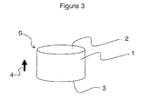
- FIG 3 shows a piezoelectric element 5 according to an embodiment of the present invention.
- the piezoelectric element 5 includes a cylindrical base member 1 composed of the piezoelectric ceramic described above and electrodes 2 and 3 provided on both surfaces of the base member 1.
- the electrodes 2 and 3 are formed over the entire circular surfaces, which are upper and lower surfaces, of the base member 1.
- polarization has been performed in the thickness direction, indicated by an arrow 4, of the base member 1.
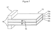
- FIG. 7 shows a shock sensor 17 using a piezoelectric element 15 according to an embodiment of the present invention.
- the piezoelectric element 15 has a bimorph structure in which plate-like base members 11 a and 11 b, each composed of the piezoelectric ceramic described above, are stacked, electrodes 12a and 12b are formed on both surfaces of the base member 11a, and electrodes 12b and 12c are formed on both surfaces of the base member 11b. Furthermore, polarization has been performed in the thickness direction, indicated by arrows 14, of the base members 11a and 11b. One end of the piezoelectric element 15 is fixed with a stationary portion 16, thus constituting the shock sensor 17 as a whole.
- Such a shock sensor 17 can be fabricated using a PZT-based piezoelectric ceramic.
- a metal plate is used for the electrode 12b or the like so that cracking does not occur when large acceleration is applied, such as in the case of being dropped.
- the electrode 12b is composed of a metal plate, sensitivity of the piezoelectric element may be degraded, or the size of the element may be increased, which is a problem.
- a sintered conductor such as Ag/Pd
- a sintered conductor such as Ag/Pd
- the electrodes 12a, 12b, and 12c can be used for the electrodes 12a, 12b, and 12c, and it is possible to fabricate a small, high-sensitivity shock sensor 17 which is difficult to break.
- a sensing portion i.e., a deflection portion extending from the stationary portion 16
- the size of a sensing portion i.e., a deflection portion extending from the stationary portion 16
- Such a shock sensor 17 can be, for example, mounted on a hard disk drive and used as a sensor for protecting against dropping shock.
- Drop shock reliability test for such a shock sensor 17 is performed, for example, by a method in which the shock sensor 17 is mounted on a 2.5-inch hard disk circuit board, and dropped naturally from a height of 1.5 m onto a concrete plane.
- the shock sensor 17 is mounted on a 2.5-inch hard disk circuit board, and dropped naturally from a height of 1.5 m onto a concrete plane.
- piezoelectric ceramics having a flexural strength of less than 200 MPa when sensor characteristics were tested after the drop test was carried out 10 times, breakage or cracking occurred in some of piezoelectric ceramics, and defects, such as spurious defects, occurred in characteristics of many piezoelectric ceramics.
- CoO powder and/or MnO 2 powder was weighed in the amounts (parts by weight) shown in Tables 1 to 4 with respect to 100 parts by weight of the main component, and mixing was performed.
- the resulting mixture was charged into a 500 ml resin pot together with zirconia balls having a purity of 99.9% and water or isopropyl alcohol (IPA), and mixing was performed for 16 hours with the resin pot being placed on a rotating table.
- IPA isopropyl alcohol
- the synthetic powder thus obtained was charged into a 500 ml resin pot together with ZrO 2 balls having a purity of 99.9% and water or isopropyl alcohol (IPA), and pulverization was performed for 20 hours with the resin pot being placed on a rotating table.
- IPA isopropyl alcohol
- the dynamic piezoelectric constant d 33 at room temperature (25°C) and the hysteresis were evaluated. Specifically, first, an offset load of 250 N was applied to the piezoelectric element 5. Thereafter, the load applied to the piezoelectric element 5 was increased to 300 N and then decreased back to 250 N, and this procedure was repeated, during which a change in the amount of charge output from the piezoelectric element 5 was measured by a charge amplifier. During this procedure, the load was applied by a triangular wave of 10 Hz.
- the rate of change in dynamic piezoelectric constant d 33 due to temperature change was calculated.
- the rate of change in dynamic piezoelectric constant d 33 due to temperature change from room temperature to T°C was calculated from the dynamic piezoelectric constant d 33 at room temperature (25°C) and the dynamic piezoelectric constant d 33 at T°C, according to the formula: (dynamic piezoelectric constant d 33 at T°C - dynamic piezoelectric constant d 33 at room temperature (25°C))/(dynamic piezoelectric constant d 33 at room temperature (25°C)).
- test pieces for measuring flexural strength were produced in the same manner as described above, and the flexural strength was evaluated by the four-point bending method according to JIS R1606. In each of the samples shown in Tables 1 and 2, the flexural strength was 182 MPa or less.
- the volume resistivity was evaluated according to JIS-C2141.
- a volume resistivity of 1 ⁇ 10 9 ⁇ m or more is evaluated to be good, which is expressed by "O" in Tables 1 to 4
- a volume resistivity of less than 1 ⁇ 10 9 ⁇ m is evaluated to be poor, which is expressed by " ⁇ " in Tables 1 to 4.
- the reason for this is that, in order to maintain detection sensitivity at a high temperature of 150°C, the piezoelectric element 5 is desired to have a volume resistivity of 1 ⁇ 10 9 ⁇ m or more.
- the output charge is suppressed from being consumed by the piezoelectric element 5, and is supplied to a signal processing circuit. Therefore, the variation in sensitivity is small, and the output charge does not decrease sensitivity or does not cause noise, thus preventing degradation in sensor characteristics.
- the results of the sample having the largest dynamic piezoelectric constant d 33 which are picked up among those produced at the different firing peak temperatures, for each composition are shown in Tables 1 to 4. Furthermore, in each composition, the dynamic piezoelectric constant d 33 of samples for which the firing peak temperature was changed was compared with the sample having the largest dynamic piezoelectric constant d 33 , and a firing temperature range in which the decrease in the dynamic piezoelectric constant d 33 was 3% or less was checked, and this range was considered as the stable firing temperature range for each composition. If the temperature range is large, the variation in the dynamic piezoelectric constant d 33 is small when the firing temperature varies during manufacturing, and it is possible to produce a piezoelectric ceramic having stable piezoelectric characteristics.
- These samples are piezoelectric ceramics within the range of the present invention, and in the piezoelectric ceramics, when a bismuth layered compound, as a main component, is represented by the composition formula Bi 4 Ti 3 O 12 ⁇ [(1- ⁇ )(M1 1- ⁇ Ln ⁇ )TiO 3 + ⁇ M2M3O 3 ], the relationships 0.3 ⁇ ⁇ ⁇ 0.95, 0 ⁇ ⁇ ⁇ 0.5, and 0 ⁇ ⁇ ⁇ 0.5 are satisfied; M1 is at least one selected from Sr, Ba, Ca, (Bi 0.5 Na 0.5 ), (Bi 0.5 K 0.5 ), and (Bi 0.5 Li 0.5 ); M2 is at least one selected from Bi, Na, K, and Li; M3 is at least one selected from Fe and Nb; and Ln represents a lanthanoid, and Co is contained in an amount of 0.01 to 0.7 parts by mass, in terms of CoO, with respect to 100 parts by mass of the main component.
- Figure 4 shows the measurement results of the load and the generated charge in Sample No. 33.
- the change in the generated charge with respect to the load is substantially linear, and the hysteresis is very small at 0.02%.
- the flexural strength is large at 200 MPa or more, and the change in the dynamic piezoelectric constant d 33 at -40°C and 150°C with respect to the dynamic piezoelectric constant d 33 at 25°C is within ⁇ 5%.
- These samples contain 0.1 parts by mass or more of Co, in terms of CoO, with respect to 100 parts by mass of the main component of the bismuth layered compound in which, in the composition formula, 0.01 ⁇ ⁇ .
- the dynamic piezoelectric constant d 33 is large at 20.1 pC/N or more.
- the dynamic piezoelectric constant d 33 is large at 20.1 pC/N or more.
- These samples contain 0.1 to 0.5 parts by mass of Co, in terms of CoO, with respect to 100 parts by mass of the main component of the bismuth layered compound in which, in the composition formula, 0.4 ⁇ ⁇ ⁇ 0.7, M2M3O 3 is BiFeO 3 , 0.1 ⁇ ⁇ ⁇ 0.3, the total content of Sr and Ba in M1 is 90 atomic percent or more, and Ln is La.
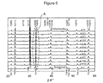
- Figure 5 shows the results of X-ray diffraction of Sample Nos. 28 to 39
- the tetragonal crystal and the orthorhombic crystal coexist, and in particular, in the range 0.4 ⁇ ⁇ ⁇ 0.45, a morphotropic phase boundary MPB is observed.
- the MPB is well known in the field of PZT piezoelectric materials, and the MPB is formed in a compositional region containing the rhombohedral crystal of PZ and the tetragonal crystal of PT at a ratio of about 1:1.
- the piezoelectric constant d has the maximum value in the vicinity of the MPB of PZT, and the temperature coefficient of the piezoelectric constant d largely varies.
- the compositional range 0.4 ⁇ ⁇ ⁇ 0.45 corresponds to a boundary between two types of crystal phase
- Figure 8 shows the results of X-ray diffraction of Sample Nos. 60, 65, and 71
- the produced samples were subjected to composition analysis using an X-ray fluorescence analysis apparatus.
- the composition of the piezoelectric ceramic of each sample had the same composition ratio as that of the composition of the raw materials prepared.
Abstract
Description
- The present invention relates to a piezoelectric ceramic and a piezoelectric element using the same, and more specifically, to a piezoelectric ceramic suitable for resonators, ultrasonic oscillators, ultrasonic motors, acceleration sensors, knocking sensors, AE sensors, and the like, and in particular, a piezoelectric ceramic preferably applicable to piezoelectric sensors utilizing a positive piezoelectric effect of thickness longitudinal vibration, and a piezoelectric element using the same.
- Products utilizing a piezoelectric ceramic include, for example, piezoelectric sensors, filters, piezoelectric resonators, ultrasonic oscillators, ultrasonic motors, and the like.
- Piezoelectric sensors are used as shock sensors, acceleration sensor, or on-vehicle knocking sensors. In particular, in recent years, research has been conducted on use of a piezoelectric sensor as a pressure sensor for directly detecting a pressure in a cylinder to optimize a timing of fuel injection from an injector in order to improve fuel efficiency and reduce exhaust gas (HC, NOx).
- A mechanism for detecting a change in pressure in a cylinder is now described. The pressure comprises, for example: a pressure transmission pin protruding in a cylinder of an engine; and a piezoelectric sensor which detects a change in pressure transmitted through the pressure transmission pin in the cylinder. A portion of a head of the pressure transmission pin protrudes inside the cylinder so as to transmit pressure in the cylinder, and the portion is subjected to high temperatures during combustion in the cylinder. Consequently, in addition to a large change in pressure, heat is also transmitted to the piezoelectric sensor connected to the pressure transmission pin, and its temperature reaches 150°C.
- Existing piezoelectric ceramics comprise, a PZT (lead zirconate titanate)-based material or a PT (lead titanate)-based material, which has a high piezoelectric property and a large piezoelectric constant d.
- However, it has been pointed out that, since the PZT- or PT-based material contains about 60% by mass of lead, there is a possibility that leaching of lead may be caused by acid rain, resulting in environmental contamination.
- In addition, since the PZT-based material or the PT-based material has a Curie temperature Tc of about 200°C to 300°C, the piezoelectric constant d decreases when used under a high temperature of about 150°C, and the piezoelectric constant d at 150°C largely varies with respect to the piezoelectric constant d at room temperature. Therefore, use thereof has been restricted greatly. For example, in the case where a piezoelectric material that is a PZT-based material or PT-based material is used as a pressure sensor which directly detects the pressure in an engine cylinder, when the piezoelectric material is subjected to a high temperature of 150°C, it changes with time, resulting in a decrease in the piezoelectric constant d. Therefore, the output voltage varies even under the same applied pressure, and since the piezoelectric constant d at 150°C largely varies with respect to the piezoelectric constant d at room temperature, linearity cannot be obtained in the relationship between pressure and output voltage, and it is difficult to calculate an accurate pressure from the output voltage.
- On the other hand, in order to obtain pressure sensor characteristics which are stable even under a high temperature of 150°C, use of a single crystal of langasite, quartz, or the like has also been studied. However, in the case of a single crystal, the piezoelectric constant d is small, which is a problem. Moreover, the single crystal is easily chipped and cracked during processing, and is easily cracked when pressure is applied during actual use. Furthermore, the production cost of the single crystal is very high, which is a problem.
- Under these circumstances, there is a high expectation for piezoelectric materials not containing lead. As a piezoelectric material not containing lead, for example,
Patent Document 1 proposes a material containing, as a main component, a bismuth layered compound. Many piezoelectric ceramics containing, as a main component, a bismuth layered compound have a Curie temperature of about 400°C or higher. Such piezoelectric materials have high heat resistance, and there is a possibility that they can be applied to piezoelectric elements used in an environment subjected to high temperatures, for example, in an engine room. - However, in the piezoelectric ceramic mainly composed of a bismuth layered compound described in
Patent Document 1, the hysteresis of the output charge caused by a positive piezoelectric effect when a load is applied is large. That is, the difference between the output charge caused in a state in which the applied load increases and the output charge caused in a state in which the applied load decreases is large, which is a problem. Accordingly, when such a piezoelectric ceramic is used, for example, as a piezoelectric element for a pressure sensor, the difference in hysteresis causes an error in the load measured, and its pressure detection accuracy is degraded.
Patent Document 1: Japanese Unexamined Patent Application Publication No.2002-167276 - It is an object of the present invention to provide a piezoelectric ceramic which has good heat resistance and a small hysteresis in the potential difference caused by a positive piezoelectric effect, and a piezoelectric element.
- A piezoelectric ceramic according to the present invention comprises a bismuth layered compound represented by the composition formula: Bi4Ti3O12·α[(1-β)(M11-γLnγ)TiO3 + βM2M3O3], (wherein α, β, and γ satisfy 0.3 ≤ α ≤ 0.95, 0 ≤ β ≤ 0.5, and 0 ≤ γ ≤ 0.5; M1 is at least one selected from Sr, Ba, Ca, (Bi0.5Na0.5), (Bi0.5K0.5), and (Bi0.5Li0.5); M2 is at least one selected from Bi, Na, K, and Li; M3 is at least one selected from Fe and Nb; and Ln represents a lanthanoid), and Co in an amount of 0.01 to 0.7 parts by mass in terms of CoO, with respect to 100 parts by mass of the bismuth layered compound.
- According to the present invention, particularly and preferably, 0.05 ≤ β ≤ 0.5.
- Preferably, M1 is SrδBa(1-δ), 0.2 ≤ δ ≤ 0.8, and γ = 0.
- Preferably, Co is contained in an amount of 0.1 parts by mass or more, in terms of CoO, with respect to 100 parts by mass of the bismuth layered compound in which 0.01 ≤ γ in the composition formula.
- Preferably, Co is contained in an amount of 0.2 parts by mass or more in terms of CoO, with respect to 100 parts by mass of the bismuth layered compound in which, in the composition formula, 0.4 ≤ α ≤ 0.7, β = 0, the total content of Sr and Ba in M1 is 90 atomic percent or more, and Ln is La.
- Preferably, Co is contained in an amount of 0.1 to 0.5 parts by mass, in terms of CoO, with respect to 100 parts by mass of the bismuth layered compound in which, in the composition formula, 0.4 ≤ α ≤ 0.7, M2M3O3 is BiFeO3, 0.1 ≤ β ≤ 0.3, the total content of Sr and Ba in M1 is 90 atomic percent or more, and Ln is La.
- A piezoelectric element according to the present invention includes a base member composed of the above piezoelectric ceramic and electrodes located on both surfaces of the base member.
- According to the piezoelectric ceramic of the present invention, since Co is contained in an amount of 0.01 to 0.7 parts by mass, in terms of CoO, with respect to 100 parts by mass of the bismuth layered compound represented by the composition formula described above, the hysteresis of dynamic piezoelectric constant d33 can be decreased.
- In particular, if 0.05 ≤ β ≤ 0.5, it is possible to obtain a piezoelectric ceramic having stable piezoelectric characteristics in which the variation in dynamic piezoelectric constant d33 is small even if the firing temperature varies.
- If M1 is SrδBa(1-δ), 0.2 ≤ δ ≤ 0.8, and γ = 0, the dynamic piezoelectric constant d33 can be increased, and the change in dynamic piezoelectric constant d33 due to temperature change can be decreased.
- If Co is contained in an amount of 0.1 parts by mass or more, in terms of CoO, with respect to 100 parts by mass of the bismuth layered compound in which, in the composition formula, 0.01 ≤ γ, the flexural strength of the piezoelectric ceramic increases, and the piezoelectric ceramic is not easily broken by stress.
- If Co is contained in an amount of 0.2 parts by mass or more, in terms of CoO, with respect to 100 parts by mass of the bismuth layered compound in which, in the composition formula, 0.4 ≤ α ≤ 0.7, β = 0, the total content of Sr and Ba in M1 is 90 atomic percent or more, and Ln is La, the dynamic piezoelectric constant d33 can be further increased.
- If Co is contained in an amount of 0.1 to 0.5 parts by mass, in terms of CoO, with respect to 100 parts by mass of the bismuth layered compound in which, in the composition formula, 0.4 ≤ α ≤ 0.7, M2M3O3 is BiFeO3, 0.1 ≤ β ≤ 0.3, the total content of Sr and Ba in M1 is 90 atomic percent or more, and Ln is La, the dynamic piezoelectric constant d33 can be further increased.
- Furthermore, according to the piezoelectric element of the present invention, the piezoelectric element has a structure in which electrodes are provided on both surfaces of a base member composed of the piezoelectric ceramic. Since the piezoelectric element is a polycrystal, it is possible to obtain a piezoelectric element which, unlike a single crystal, does not have a property of being easily cracked along a specific plane, in which flaws, such as chipping, do not easily occur, and the amount of defects due thereto decreases, and which has a good yield.
-
Figure 1 is a schematic illustration showing an apparatus for evaluating the dynamic piezoelectric constant d33 of a piezoelectric ceramic. -
Figure 2 is a diagram showing a hysteresis of generated charge. -
Figure 3 is a perspective view of a pressure sensor which is an embodiment of a piezoelectric element of the present invention. -
Figure 4 is a diagram showing the relationship between the load and the generated charge for a piezoelectric ceramic of Sample No. 33. -
Figure 5 is an X-ray diffraction chart of piezoelectric ceramics of Sample Nos. 28 to 39. -
Figure 6 is an enlarged view of the section A of the X-ray diffraction chart shown inFigure 5 . -
Figure 7 is a perspective view of a shock sensor which is an embodiment of a piezoelectric element of the present invention. -
Figure 8 is an X-ray diffraction chart of piezoelectric ceramics of Sample Nos. 101, 106, and 112. -
Figure 9 is an enlarged view of the section B of the X-ray diffraction chart shown inFigure 8 . - A piezoelectric ceramic of the present invention contains a bismuth layered compound, as a main component, represented by the composition formula Bi4Ti3O12·α[(1-β)(M11-γLnγ)TiO3 + βM2M3O3], wherein α, β, and γ satisfy the relationships 0.3 ≤ α ≤ 0.95, 0 ≤ β ≤ 0.5, and 0 ≤ γ ≤ 0.5; M1 is at least one selected from Sr, Ba, Ca, (Bi0.5Na0.5), (Bi0.5K0.5), and (Bi0.5Li0.5); M2 is at least one selected from Bi, Na, K, and Li; M3 is at least one selected from Fe and Nb; and Ln represents a lanthanoid, and Co in an amount of 0.01 to 0.7 parts by mass in terms of CoO, with respect to 100 parts by mass of the main component.
- First, the output charge caused by a positive piezoelectric effect and a hysteresis thereof is now described. The output charge caused by a positive piezoelectric effect can be measured, for example, using an apparatus shown in
Figure 1 . In the apparatus, a load Flow is applied to apiezoelectric element 5 includingelectrodes piezoelectric element 5 is increased to Fhigh and then decreased to Flow, and this procedure is repeated, during which the output charge Q generated in thepiezoelectric element 5 is measured by a charge amplifier. During this procedure, the load is applied, for example, by a triangular wave of 10 Hz in which Flow = 250 N and Fhigh = 300 N. - The relationship between the load and the output charge measured in such a manner is, for example, shown in
Figure 2 . In the graph, the arrows indicate whether measurement is made when the load is increased or measurement is made when the load is decreased. InFigure 2 , the output charge measured when the applied load is increased is lower. Q0 represents the output charge at the load Flow, Q1 represents the output charge at the load Fmid (= (Flow + Fhigh)/2) when the load is increased, Q2 represents the output charge at the load Fhigh, and Q3 represents the output charge at the load Fmid when the load is decreased. Q1 and Q3 do not coincide with each other, and a difference therebetween corresponds to a hysteresis. Hereinafter, the value (Q3 - Q1)/(Q2 - Q0) is considered as an index of hysteresis, and simply referred to as "hysteresis". The value of hysteresis is preferably 1% or less, and particularly preferably 0.5% or less. Note that the hysteresis is basically 0 or more. - Next, the dynamic piezoelectric constant d33 is described. The dynamic piezoelectric constant d33 is determined according to the formula described below, using the observed value of output voltage when a load is directly applied to the
piezoelectric element 5. Conventionally, the piezoelectric constant d33 has been measured using a resonance impedance method. However, in that method, since the load applied to thepiezoelectric element 5 is small, the dynamic characteristic at the time of applying an actual load cannot be evaluated. Therefore, the piezoelectric constant d33 (= output charge/change in load) is measured from the relationship between load and output charge at the time of applying an actual load, and this is considered as the dynamic piezoelectric constant d33. - The specific measurement apparatus and measurement method are the same as those in the case of the hysteresis measurement described above. For example, first, an offset load of 250 N is applied to the
piezoelectric element 5, and a load of 50 N in the form of a triangle wave is applied in addition to the offset load. The output charge Q at the peak load of 50 N of the triangle wave applied to thepiezoelectric element 5 is measured by a charge amplifier. From the relationship between the applied load of 50 N and the output charge Q, the dynamic piezoelectric constant d33 is determined to be d33 = Q/50N (change in load). That is, the dynamic piezoelectric constant d33 has a unit of measure of C (coulomb)/N, and means a piezoelectric constant d33 in a dynamic state at the time of applying a load to the piezoelectric element. - The reason for applying an offset load of 250 N is that by preventing a tensile force from being applied to the
piezoelectric element 5, stable output characteristics are obtained. Furthermore, a change in load is set at 50 N in order to exemplify, for example, a range required for detecting a change in pressure in a cylinder of an engine as an application example. - The reason for setting the range 0.3 ≤ α ≤ 0.95 in the composition formula is that, if α is less than 0.3, the hysteresis increases. Furthermore, if α is less than 0.3, leakage current increases, and the dynamic piezoelectric constant d33 decreases. On the other hand, if α exceeds 0.95, the hysteresis increases, and the dynamic piezoelectric constant d33 decreases.
- M1 is at least one selected from Sr, Ba, Ca, (Bi0.5Na0.5), (Bi0.5K0.5), and (Bi0.5Li0.5). If the molar percentage of Si in M1 is high, the dynamic piezoelectric constant d33 can be increased, which is preferable. If the molar percentage of Ba in M1 is high, the hysteresis can be decreased, which is preferable. The molar percentage of Ba in M1 is preferably 20% or more, and particularly preferably 40% or more. If the molar percentage of Ca in M1 is high, linearity of the change in dynamic piezoelectric constant d33 with respect to temperature improves, which is preferable. Furthermore, if the total molar percentage of Ba and Ca in M1 is high, the temperature dependence of the dynamic piezoelectric constant d33 decreases, which is preferable.
- Furthermore, in the case where M1 contains at least one of (Bi0.5Na0.5), (Bi0.5K0.5), and (Bi0.5Li0.5), sinterability of the piezoelectric ceramic improves. The sinterability improves as the total molar percentage of (Bi0.5Na0.5), (Bi0.5K0.5), and (Bi0.5Li0.5) in M1 increases. Since (Bi0.5Na0.5), (Bi0.5K0.5), and (Bi0.5Li0.5) are each divalent in average, they can be mixed for use at any ratio with Sr, Ba, and Ca.
- In order to increase the dynamic piezoelectric constant d33 and decrease the temperature dependence of the dynamic piezoelectric constant d33, preferably, M1 is SrδBa(1-δ), and 0.2 ≤ δ ≤ 0.8. In order to further decrease the hysteresis, more preferably 0.4 ≤ δ ≤ 0.8, and particularly preferably 0.4 ≤ δ ≤ 0.6.
- The reason for setting the substitution amount β of M2M3O3, in which M2 is at least one selected from Bi, Na, K, and Li, and M3 is at least one selected from Fe and Nb, so as to satisfy 0 ≤ β ≤ 0.5 is that, if β exceeds 0.5, the dynamic piezoelectric constant d33 decreases. M2M3O3 has the effect of expanding the range of firing temperature at which stable characteristics can be obtained (stable firing temperature range). If 0 ≤ β ≤ 0.05, the stable firing temperature range can be set within a range of about 10°C or less. Furthermore, if 0.05 ≤ β ≤ 0.5, sinterability improves, and the stable firing temperature range can be expanded to about 15°C to 30°C without substantially decreasing the dynamic piezoelectric constant d33. The range 0.1 ≤ β ≤ 0.3 is more preferable because the stable firing temperature range can be expanded, and a decrease in the dynamic piezoelectric constant d33 can be reduced significantly. In addition, in view of expanding the stable firing temperature range, particularly preferably, M2M3O3 is BiFeO3.
- Next, the amount of Co contained with respect to 100 parts by mass of the Bi4Ti3O12·α[(1-β)(M11-γLnγ)TiO3 + βM2M3O3] component is described. If the content of Co, in terms of CoO, is less than 0.01 parts by mass, the dynamic piezoelectric constant d33 decreases, and the hysteresis increases. On the other hand, if the content of Co, in terms of CoO, exceeds 0.7 parts by mass, the hysteresis also increases. The content of CoO is preferably 0.1 to 0.3 parts by mass, at which the hysteresis can be further decreased, and particularly preferably 0.2 to 0.3 parts by mass.
- The reason for the decrease in hysteresis is believed to be that, if the piezoelectric ceramic is subjected to a change in pressure, a change in the ferroelectric domain structure does not easily occur, and since the charge caused by the positive piezoelectric effect is supplied to the detection apparatus without being consumed in the ceramic, a drift in output charge is significantly decreased.
- Since the bismuth layered compound is composed of tabular crystals and difficult to sinter, MnO2 may be added thereto as a sintering aid. In such a case, preferably, Mn is added in an amount of 0.1 parts by mass or less, in terms of MnO2, with respect to 100 parts by mass of the Bi4Ti3O12·α[(1-β)(M11-γLnγ)TiO3 + βM2M3O3] component. If the amount of Mn, in terms of MnO2, exceeds 0.1 parts by mass, there is a possibility that the hysteresis may be increased.
- Ln is specifically at least one selected from La, Ce, Pr, Nd, Pm, Sm, Eu, Gd, Tb, Dy, Ho, Er, Tm, Yb, and Lu. By incorporating Ln and Co in the ranges described above, the flexural strength of the piezoelectric ceramic can be set at 200 MPa or more. The reason for setting the substitution amount γ of Ln so as to satisfy 0.01 ≤ γ ≤ 0.5 is that, if γ is less than 0.01, the flexural strength decreases. Furthermore, if γ exceeds 0.5, the dynamic piezoelectric constant d33, which will be described below, decreases. lf γ is 0.4 or more, the optimum firing temperature range expands, which is preferable. Furthermore, among lanthanoids, La and Nd are preferable from the standpoint that the optimum firing temperature range expands, and in particular, La is preferable from the standpoint that the dynamic piezoelectric constant d33 increases.
- Taking all the factors described above into consideration, when Co is incorporated in an amount of 0.2 to 1 part by mass, in terms of CoO, with respect to 100 parts by mass of the bismuth layered compound (main component) in which 0.4 ≤ α ≤ 0.7, β = 0, the total content of Sr and Ba in M1 is 90 atomic percent or more, and Ln is La, the dynamic piezoelectric constant d33 of the piezoelectric ceramic can be set at 20 pC/N. Furthermore, by incorporating Co in an amount of 0.1 to 0.5 parts by mass, in terms of CoO, with respect to 100 parts by mass of the bismuth layered compound (main component) in which 0.4 ≤ α ≤ 0.7, M2M3O3 is BiFeO3, 0.1 ≤ β ≤ 0.3, the total content of Sr and Ba in M1 is 90 atomic percent or more, and Ln is La, the dynamic piezoelectric constant d33 of the piezoelectric ceramic can be set at 20 pC/N.
- The piezoelectric ceramic according to the present invention, the composition formula of which is represented by Bi4Ti3O12·α[(1-β)(M11-γLnγ)TiO3 + βM2M3O3], has a main crystal phase composed of a bismuth layered compound. Basically, this is believed to a bismuth layered compound represented by Bi4T3O12·αM1TiO3, in which part of M1 constituting the pseudo-perovskite layer of the bismuth layered compound is replaced by M2, and part of Ti is replaced by M3. That is, in the piezoelectric ceramic of the present invention, in a bismuth layered structure represented by the general formula (Bi2O2)2+(αm-1αmO3m+1)2-, by adjusting the types and amounts of constituent elements coordinated to the α site, the α site, and the oxygen site, it is possible to obtain a bismuth layered structure having a morphotropic phase boundary (MPB) in which there are both a tetragonal crystal produced if m = 4 and an orthorhombic crystal produced if m = 3. As a result, it is possible to realize characteristic piezoelectric properties in the vicinity of the MPB composition, which is also known in PZT, in the bismuth layered compound.
- Furthermore, there may be cases where Co is dissolved as a solid solution in the main crystal phase and partially precipitated as crystals of Co compounds in the grain boundaries, or there may be cases where there are, as other crystal phases, a pyrochlore phase, a perovskite phase, and bismuth layered compounds having different structures. However, as long as the amount thereof is very small, no problem arises in terms of properties.
- In some cases, Zr or the like may be mixed into the piezoelectric ceramic of the present invention from ZrO2 balls during pulverization. However, as long as the amount thereof is very small, no problem arises in terms of properties.
- In the piezoelectric ceramic of the present invention, as raw materials, for example, various oxides including SrCO3, BaCO3, CaCO3, Nb2O5, Bi2O3, TiO2, Na2CO3, K2CO3, Li2CO3, Fe2O3, Ln2O3, and CoO, or salts thereof can be used. Ln is at least one selected from La, Ce, Pr, Nd, Pm, Sm, Eu, Gd, Tb, Dy, Ho, Er, Tm, Yb, and Lu. The raw materials are not limited thereto, and metal salts, such as carbonates and nitrates, which produce oxides upon firing may be used.
- These raw materials are weighed such that, when a bismuth layered compound, as a main component, is represented by the formula Bi4Ti3O2·α[(1-)(M11-γLnγ)TiO3 + βM2M3O3], 0.3 ≤ α ≤ 0.95, 0 ≤ β ≤ 0.5, and 0 ≤ γ ≤ 0.5 are satisfied; M1 is at least one selected from Sr, Ba, Ca, (Bi0.5Na0.5), (Bi0.5K0.5), and (Bi0.5Li0.5); M2 is at least one selected from Bi, Na, K, and Li; M3 is at least one selected from Fe and Nb; and Ln represents a lanthanoid, and such that Co is contained in an amount of 0.01 to 0.7 parts by mass, in terms of CoO, with respect to 100 parts by mass of the bismuth layered compound. The powders weighed and mixed are pulverized such that the mean particle size distribution (D50) is in the range of 0.5 to 1 µm, and the mixture is calcined at 800°C to 1,050°C. A predetermined organic binder is added thereto, and the resulting mixture is wet-mixed and granulated. The powder thus obtained is formed into a predetermined shape by known press forming or the like, and firing is performed in an oxidizing atmosphere, such as in the air, in a temperature range of 1,050°C to 1,250°C for 2 to 5 hours. Thereby, a piezoelectric ceramic of the present invention is obtained.
- The piezoelectric ceramic of the present invention is most suitable as a piezoelectric ceramic for pressure sensors, and in addition, can be used for piezoelectric resonators, ultrasonic oscillators, ultrasonic motors, and piezoelectric sensors, such as acceleration sensors, knocking sensors, and AE sensors.
-
Figure 3 shows apiezoelectric element 5 according to an embodiment of the present invention. Thepiezoelectric element 5 includes acylindrical base member 1 composed of the piezoelectric ceramic described above andelectrodes base member 1. Referring toFigure 3 , theelectrodes base member 1. Furthermore, polarization has been performed in the thickness direction, indicated by anarrow 4, of thebase member 1. When such apiezoelectric element 5 is used for directly detecting a pressure in an automotive engine cylinder, for example, even if a high load of 500 N is applied at a high temperature of 150°C, the piezoelectric element operates stably without being broken. According to simulation stress analysis, even when a load of 500 N is applied, the maximum principal stress generated in thepiezoelectric element 5 is about one-tenth or less of the mechanical strength of the piezoelectric ceramic constituting thebase member 1. -
Figure 7 shows ashock sensor 17 using apiezoelectric element 15 according to an embodiment of the present invention. Thepiezoelectric element 15 has a bimorph structure in which plate-like base members electrodes base member 11a, andelectrodes base member 11b. Furthermore, polarization has been performed in the thickness direction, indicated byarrows 14, of thebase members piezoelectric element 15 is fixed with astationary portion 16, thus constituting theshock sensor 17 as a whole. When shock (acceleration) is applied from the outside to theshock sensor 17, the other end of thepiezoelectric element 15 is displaced with respect to thestationary portion 16, and the charge generated in thepiezoelectric element 15, which is deflected in the stacking direction, is measured by a potential difference between theelectrode 12b and each of theelectrodes shock sensor 17. - Such a
shock sensor 17 can be fabricated using a PZT-based piezoelectric ceramic. However, in the PZT-based piezoelectric ceramic, since the flexural strength is about 80 MPa at a maximum, a metal plate is used for theelectrode 12b or the like so that cracking does not occur when large acceleration is applied, such as in the case of being dropped. However, when theelectrode 12b is composed of a metal plate, sensitivity of the piezoelectric element may be degraded, or the size of the element may be increased, which is a problem. - In contrast, in a piezoelectric ceramic having a flexural strength of 200 MPa or more, as in the piezoelectric ceramic according to the present invention, a sintered conductor, such as Ag/Pd, can be used for the
electrodes sensitivity shock sensor 17 which is difficult to break. For example, usingbase members stationary portion 16, is set to be 1.0 mm in length × 0.21 mm in width × 30 µm in thickness, it is possible to fabricate ashock sensor 17 having a bimorph structure including two layers. Such ashock sensor 17 can be, for example, mounted on a hard disk drive and used as a sensor for protecting against dropping shock. - Drop shock reliability test for such a
shock sensor 17 is performed, for example, by a method in which theshock sensor 17 is mounted on a 2.5-inch hard disk circuit board, and dropped naturally from a height of 1.5 m onto a concrete plane. In the case of piezoelectric ceramics having a flexural strength of less than 200 MPa, when sensor characteristics were tested after the drop test was carried out 10 times, breakage or cracking occurred in some of piezoelectric ceramics, and defects, such as spurious defects, occurred in characteristics of many piezoelectric ceramics. In contrast, in the case of piezoelectric ceramics having a flexural strength of 200 MPa or more, occurrences of cracking or changes in characteristics are not substantially observed, and the failure probability according to the Weibull evaluation can be reduced to 1 ppm or less. - The present invention is described in detail with using examples below. However, it is to be understood that the present invention is not limited to the examples below.
- First, as starting materials, SrCO3 powder, BaCO3 powder, CaCO3 powder, Bi2O3 powder, TiO2 powder, Na2CO3 powder, K2CO3Q powder, Li2CO3 powder, Fe2O3 powder, Nb2O5 powder, and Ln2O3 powder, each having a purity of 99.9%, were weighed such that, when a composition formula by the molar ratio was represented by Bi4Ti3O12·α[(1-β)(M11-γLnγ)TiO3·βM2M3O3], M1, M2, M3, Ln, α, β, and γ were elements or mixing ratios shown in Tables 1 to 4.
- CoO powder and/or MnO2 powder was weighed in the amounts (parts by weight) shown in Tables 1 to 4 with respect to 100 parts by weight of the main component, and mixing was performed. The resulting mixture was charged into a 500 ml resin pot together with zirconia balls having a purity of 99.9% and water or isopropyl alcohol (IPA), and mixing was performed for 16 hours with the resin pot being placed on a rotating table.
- After mixing, the resulting slurry was dried in the air and passed through a No. 40 mesh. Then, the resulting product was calcined by being retained in the air at 950°C for 3 hours. The synthetic powder thus obtained was charged into a 500 ml resin pot together with ZrO2 balls having a purity of 99.9% and water or isopropyl alcohol (IPA), and pulverization was performed for 20 hours with the resin pot being placed on a rotating table.
- An appropriate amount of an organic binder was added to the powder thus obtained, and granulation was performed. The resulting granules were formed into a cylindrical shaped body by die pressing at a load of 150 MPa, followed by binder removal. Then, firing was performed in the air atmosphere, at a peak temperature at which the dynamic piezoelectric constant d33 of each sample had the largest value between 1,050°C and 1,250°C, for 3 hours. Thereby, a disk-like piezoelectric ceramic having a diameter of 4 mm and a thickness of 2 mm was obtained. Furthermore, piezoelectric ceramics were produced by firing while varying the firing peak temperature in steps of 5°C within the range of -20°C to +20°C with respect to the firing peak temperature at which the dynamic piezoelectric constant d33 had the largest value.
- Then, Ag electrodes were attached by baking to both main surfaces of the cylindrical piezoelectric ceramic, and polarization treatment was performed under a condition of 200°C by applying a DC voltage of 5 kV/mm or more in the thickness direction, followed by thermal aging at 300°C for 24 hours.
- Next, using the apparatus shown in
Figure 1 , the dynamic piezoelectric constant d33 at room temperature (25°C) and the hysteresis were evaluated. Specifically, first, an offset load of 250 N was applied to thepiezoelectric element 5. Thereafter, the load applied to thepiezoelectric element 5 was increased to 300 N and then decreased back to 250 N, and this procedure was repeated, during which a change in the amount of charge output from thepiezoelectric element 5 was measured by a charge amplifier. During this procedure, the load was applied by a triangular wave of 10 Hz. The dynamic piezoelectric constant d33 was calculated according to the formula: dynamic piezoelectric constant d33 = output charge/change in load (units: pC/N). Similarly, by measuring the dynamic piezoelectric constant d33 at -40°C and 150°C, the rate of change in dynamic piezoelectric constant d33 due to temperature change was calculated. The rate of change in dynamic piezoelectric constant d33 due to temperature change from room temperature to T°C was calculated from the dynamic piezoelectric constant d33 at room temperature (25°C) and the dynamic piezoelectric constant d33 at T°C, according to the formula: (dynamic piezoelectric constant d33 at T°C - dynamic piezoelectric constant d33 at room temperature (25°C))/(dynamic piezoelectric constant d33 at room temperature (25°C)). - Furthermore, test pieces for measuring flexural strength were produced in the same manner as described above, and the flexural strength was evaluated by the four-point bending method according to JIS R1606. In each of the samples shown in Tables 1 and 2, the flexural strength was 182 MPa or less.
- Furthermore, the volume resistivity was evaluated according to JIS-C2141. A volume resistivity of 1 × 10⁹ Ω·m or more is evaluated to be good, which is expressed by "O" in Tables 1 to 4, and a volume resistivity of less than 1 × 10⁹ Ω·m is evaluated to be poor, which is expressed by "×" in Tables 1 to 4. The reason for this is that, in order to maintain detection sensitivity at a high temperature of 150°C, the
piezoelectric element 5 is desired to have a volume resistivity of 1 × 10⁹ Ω·m or more. When the volume resistivity is higher than this value, the output charge is suppressed from being consumed by thepiezoelectric element 5, and is supplied to a signal processing circuit. Therefore, the variation in sensitivity is small, and the output charge does not decrease sensitivity or does not cause noise, thus preventing degradation in sensor characteristics. - The results of the sample having the largest dynamic piezoelectric constant d33 which are picked up among those produced at the different firing peak temperatures, for each composition are shown in Tables 1 to 4. Furthermore, in each composition, the dynamic piezoelectric constant d33 of samples for which the firing peak temperature was changed was compared with the sample having the largest dynamic piezoelectric constant d33, and a firing temperature range in which the decrease in the dynamic piezoelectric constant d33 was 3% or less was checked, and this range was considered as the stable firing temperature range for each composition. If the temperature range is large, the variation in the dynamic piezoelectric constant d33 is small when the firing temperature varies during manufacturing, and it is possible to produce a piezoelectric ceramic having stable piezoelectric characteristics.
-
Table 1 Sample No. Composition Stable firing temperature range Dynamic piezoelectric constant d33 Hysteresis Rate of change in dynamic piezoelectric constant d33 due to temperature change Volume resistivity M1 α M2 M3 β Ln γ Additive 25→-40°C 25→150°C Composition parts by mass °C pC/N % % % * 1 Sr0.5Ba0.5 0 - - - - - CoO 0.2 10 5.3 1.8 1.1 5.5 × * 2 Sr0.5Ba0.5 0.2 - - - - - CoO 0.2 10 8.7 1.5 0.8 2.8 × 3 Sr0.5Ba0.5 0.3 - - - - - CoO 0.2 10 18.5 0.5 1 -0.18 ○ 4 Sr0.5Ba0.5 0.4 - - - - - CoO 0.2 10 20.8 0.11 0.8 -0.2 ○ 5 Sr0.5Ba0.5 0.43 - - - - - CoO 0.2 10 21.1 0.08 -0.08 0.3 ○ 6 Sr0.5Ba0.5 0.45 - - - - - CoO 0.2 10 22.3 0.07 -0.05 0.24 ○ 7 Sr0.5Sa0.5 0.47 - - - - - CoO 0.2 10 20.4 0.06 -0.05 0.18 ○ 8 Sr0.5Ba0.5 0.5 - - - - - CoO 0.2 10 20.3 0.17 -0.07 1.3 ○ 9 Sr0.5Ba0.5 0.7 - - - - - CoO 0.2 10 18.9 0.32 -0.11 2.8 ○ 10 Sr0.5Ba0.5 0.9 - - - - - CoO 0.2 10 17.8 0.5 -0.15 3.4 ○ 11 Sr0.5Ba0.5 0.95 - - - - - CoO 0.2 10 16.5 0.83 -0.18 3.8 ○ * 12 Sr0.5Ba0.5 1 - - - - - CoO 0.2 10 15.8 1.34 -2.51 6.7 ○ 13 Sr 0.45 - - - - - CoO 0.2 10 20.6 0.85 -0.11 5.3 ○ 14 Sr0.8Ba0.2 0.45 - - - - - CoO 0.2 10 20.3 0.55 -0.18 4.1 ○ 15 Sr0.6Ba0.4 0.45 - - - - CoO 0.2 10 19.9 0.24 -0.09 2.5 ○ 16 Sr0.4Ba0.6 0.45 - - - - - CoO 0.2 10 18.6 0.11 -0.06 1.3 ○ 17 Sr0.2Ba0.8 0.45 - - - - - CoO 0.2 10 16.3 0.14 -0.05 1.1 ○ 18 Ba 0.45 - - - - - CoO 0.2 10 15.3 0.22 -0.05 0.7 ○ 19 Ca 0.45 - - - - - CoO 0.2 10 15.1 0.42 -0.13 0.8 ○ * 20 Sr0.5Ba0.5 0.45 - - - - - - - Unable to measure because of sample breakage 21 Sr0.5Ba0.5 0.45 - - - - - CoO 0.01 10 16.8 0.74 -0.7 1.3 ○ 22 Sr0.5Ba0.5 0.45 - - - - - CoO 0.1 10 18.8 0.32 -0.55 1.5 ○ 23 Sr0.5Ba0.5 0.45 - - - - - CoO 0.3 10 23.8 0.14 -0.51 2.6 ○ 24 Sr0.5Ba0.5 0.45 - - - - - CoO 0.5 10 24.5 0.33 -0.37 3.7 ○ 25 Sr0.5Ba0.5 0.45 - - - - - CoO 0.7 10 25.6 0.88 -0.32 4.3 ○ * 26 Sr0.5Ba0.5 0.45 - - - - - CoO 0.8 10 25.3 1.35 -0.78 4.7 ○ 27 Sr0.5Ba0.5 0.45 - - - - - CoO 0.1 10 17.7 0.88 -0.12 0.84 ○ MnO2 0.1 Asterisk (*) indicates sample out of range of present invention -
Table2 Sample No. Composition Stable firing temperature range Dynamic piezoelectric constant d33 Hysteresis Rate of change in dynamic piezoelectric constant d33 due to temperature Volume resistivity M1 α M2 M3 β Ln γ Additive 25→-40°C 25→150°C Composition parts by mass °C pC/N % % % * 28 Sr0.5Ba0.5 0 Bi Fe 0 - - CoO 0.2 30 8 2 -2.3 5.8 × * 29 Sr0.5Ba0.5 0.2 Bi Fe 0 - - CoO 0.2 30 13.1 1.5 -1.9 4.3 × 30 Sr0.5Ba0.5 0.3 Bi Fe 0 - - CoO 0.2 30 19.4 0.5 -1.7 4.9 ○ 31 Sr0.5Ba0.5 0.4 Bi Fe 0 - - CoO 0.2 30 21.8 0.2 -0.1 3 ○ 32 Sr0.5Ba0.5 0.4 Bi Fe 0 - - CoO 0.2 30 22.2 0.01 -0.08 0.48 ○ 33 Sr0.5Ba0.5 0.5 Bi Fe 0 - - CoO 0.2 30 22.8 0.02 -0.05 0.75 ○ 34 Sr0.5Ba0.5 0.5 Bi Fe 0 - - CoO 0.2 30 21.1 0.05 -0.05 1.1 ○ 35 Sr0.5Ba0.5 0.5 Bi Fe 0 - - CoO 0.2 30 20.7 0.11 -0.07 3.6 ○ 36 Sr0.5Ba0.5 0.7 Bi Fe 0 - - CoO 0.2 30 20.5 0.5 -0.11 4.1 ○ 37 Sr0.5Ba0.5 0.9 Bi Fe 0 - - CoO 0.2 30 17.8 0.8 -0.15 4.3 ○ 38 Sr0.5Ba0.5 1 Bi Fe 0 - - CoO 0.2 30 17.7 0.97 -0.18 4.8 ○ * 39 Sr0.5Ba0.5 1 Bi Fe 0 - - CoO 0.2 30 14.8 1.8 -2.51 6.7 ○ 40 Sr 0.5 Bi Fe 0 - - CoO 0.2 30 21.8 0.85 -0.11 5.1 ○ 41 Sr0.8Ba0.2 0.5 Bi Fe 0 - - CoO 0.2 30 21.5 0.55 -0.18 3.4 ○ 42 Sr0.8Ba0.4 0.5 Bi Fe 0 - - CoO 0.2 30 21.1 0.24 -0.09 2.2 ○ 43 Sr0.4Ba0.6 0.5 Bi Fe 0 - - CoO 0.2 30 19.8 0.21 -0.06 1 ○ 44 Sr0.2Be0.8 0.5 Bi Fe 0 - - CoO 0.2 30 17.5 0.2 -0.05 0.8 ○ 45 Ba 0.5 Bi Fe 0 - - CoO 0.2 30 15.2 0.35 -0.05 0.8 ○ 46 Ca 0.5 Bi Fe 0 - - CoO 0.2 30 15.4 0.42 0.16 -0.7 ○ 47 Sr0.5Ba0.5 0.5 Bi Fe 0 - - CoO 0.2 10 21.1 0.11 -0.05 1.8 ○ 48 Sr0.5Bs0.5 0.5 Bi Fe 0 - - CoO 0.2 15 21.8 0.2 -0.09 1.8 ○ 49 Sr0.5Ba0.5 0.5 Bi Fe 0 - - CoO 0.2 35 20.8 0.37 -0.07 1.9 ○ 50 Sr0.5Ba0.5 0.5 Bi Fe 1 - - CoO 0.2 40 19.5 0.77 -0.08 1.3 ○ * 51 Sr0.5Ba0.5 0.5 Bi Fe 1 - - CoO 0.2 45 18.4 1.13 -0.08 1.2 ○ * 52 Sr0.5Ba0.5 0.5 Bi Fe 0 - - - - 30 18.3 1.6 -1.5 5.3 ○ 53 Sr0.5Ba0.5 0.5 Bi Fe 0 - - CoO 0.01 30 19.4 0.73 -1.4 4.2 ○ 54 Sr0.5Ba0.5 0.5 Bi Fe 0 - - CoO 0.1 30 20.5 0.15 -1.1 2.4 ○ 55 Sr0.5Ba0.5 0.5 Bi Fe 0 - - CoO 0.3 30 21 0.65 -1.1 1.6 ○ 56 Sr0.5Ba0.5 0.5 Bi Fe 0 - - CoO 0.5 30 22.8 0.9 -1.3 1.5 ○ 57 Sr0.5Ba0.5 0.5 Bi Fe 0 - - CoO 0.7 30 24.9 0.98 -1.8 1.5 ○ * 58 Sr0.5Ba0.5 0.5 Bi Fe 0 - - CoO 0.8 30 25.7 2.15 -2.1 1.46 ○ 59 Sr0.5Ba0.5 0.5 Bi Fe 0 - - CoO 0.1 30 22.5 0.25 -1.5 1.1 ○ MnO2 0.1 Asterisk (*) indicates sample out of range of present invention -
[Table 3] Sample No. Composition Stable firing temperature range Dynamic piezoelectric constant d33 Hysteresis Rate of change in dynamic piezoelectric constant d33 due to temperature change Fiexura l strengt h Volume resistivity M1 α M2 M3 β Ln γ Additive 25→40°C 25→150°C Composition parts by mass °C pC/N % % % MPa * 60 Sr0.5Ba0.5 0 - - - La 0 CoO 0.2 5 3.2 1.82 1.1 8.7 220 × * 61 Sr0.5Ba0.5 0.2 - - - La 0 CoO 0.2 10 6.2 1.5 1.1 4.8 222 × 62 Sr0.5Ba0.5 0.3 - - - La 0 CoO 0.2 15 18.5 0.52 1 -0.18 238 ○ 63 Sr0.5Ba0.5 0.4 - - - La 0 CoO 0.2 15 21.9 0.16 0.8 -0.2 245 ○ 64 Sr0.5Ba0.5 0.4 - - - La 0 CoO 0.2 15 22.1 0.13 -0.08 0.3 238 ○ 65 Sr0.5Ba0.5 0.5 - - - La 0 CoO 0.2 15 23.4 0.09 -0.05 0.24 240 ○ 66 Sr0.5Ba0.5 0.5 - - - La 0 CoO 0.2 15 21.8 0.01 -0.05 0.18 235 ○ 67 Sr0.5Ba0.5 0.5 - - - La 0 CoO 0.2 15 20.3 0.13 -0.08 1.02 235 ○ 68 Sr0.5Ba0.5 0.7 - - - La 0 CoO 0.2 15 20.1 0.27 -0.34 1.95 220 ○ 69 Sr0.5Ba0.5 0.9 - - - La 0 CoO 0.2 10 18.4 0.56 -0.64 3.22 210 ○ 70 Sr0.5Ba0.5 1 - - - La 0 CoO 0.2 15 17.7 0.86 -1 4.21 215 ○ * 71 Sr0.5Ba0.5 1 - - - La 0 CoO 0.2 15 16.3 1.33 -2.22 7.15 213 ○ 72 Sr 0.5 - - - La 0 CoO 0.2 15 20.6 0.89 -1.01 4.32 212 ○ 73 Ba 0.5 - - - La 0 CoO 0.2 10 20.1 0.26 -0.95 1.37 223 ○ 74 Ca 0.5 - - - La 0 CoO 0.2 10 15.1 0.38 -0.85 1.25 210 ○ 75 Sr0.45Ba0.45Ca0.1 0.5 - - - La 0 CoO 0.2 15 23.4 0.54 -0.58 0.74 226 ○ 76 Ba0.85(Bi0.5Na0.5)0.05 0.5 - - - La 0 CoO 0.2 15 22.5 0.3 -1.38 2.08 230 ○ 77 Sr0.5(Bi0.5Li0.5)0.5 0.5 - - - La 0 CoO 0.2 15 17.4 0.07 -1.28 3.87 240 ○ 78 Sr0.5(Bi0.5K0.5)0.5 0.5 - - - La 0 CoO 0.2 10 15.8 0.09 -2.01 4.44 210 ○ 79 Sr0.5Ba0.5 0.5 - - - - - CoO 0.2 10 22.3 0.07 -0.05 0.24 170 ○ 80 Sr0.5Ba0.5 0.5 - - - La 0 CoO 0.2 10 21.4 0.15 -0.81 1.28 235 ○ 81 Br0.5Ba0.5 0.5 - - - La 0 CoO 0.2 15 23.4 0.18 -0.41 0.76 240 ○ 82 Sr0.5Ba0.5 0.5 - - - La 0 CoO 0.2 15 24.1 0.25 -0.07 0.34 240 ○ 83 Sr0.5Ba0.5 0.5 - - - La 0 CoO 0.2 20 20.2 0.3 -0.18 0.84 240 ○ 84 Sr0.5Ba0.5 0.5 - - - La 1 CoO 0.2 20 25.7 0.65 -0.05 0.88 240 ○ * 85 Sr0.5Ba0.5 0.5 - - - La 1 CoO 0.2 20 9.4 0.92 -0.33 1.19 277 × 86 Sr0.5Ba0.5 0.5 - - - Nd 0 CoO 0.2 10 19.9 0.33 -0.08 0.3 200 ○ 87 Sr0.5Ba0.5 0.5 - - - Nd 0 CoO 0.2 15 17.5 0.3 -0.3 1.25 210 ○ 88 Sr0.5Ba0.5 0.5 - - - Nd 1 CoO 0.2 20 15.5 0.35 -1.23 2.83 275 ○ * 89 Sr0.5Ba0.5 0.5 - - - Nd 1 CoO 0.2 20 7.3 0.31 -1.3 2.97 280 ○ * 90 Sr0.5Ba0.5 0.5 - - - La 0 - - Unable to measure because of sample breakage 91 Sr0.5Ba0.5 0.5 - - - La 0 CoO 0.1 10 18.8 0.69 -0.55 1.5 277 ○ 92 Sr0.5Ba0.5 0.5 - - - La 0 CoO 0.5 10 24.5 0.27 -0.37 2.7 265 ○ 93 Sr0.5Ba0.5 0.5 - - - La 0 CoO 0.7 10 24,1 0.84 -0.79 2.8 256 ○ * 94 Sr0.5Ba0.5 0.5 - - - La 0 CoO 1 15 24.3 1.28 -1.33 2.87 268 ○ * 95 Sr0.5Ba0.5 0.5 - - - La 0 CoO 1.5 20 21.4 2.53 -1.12 3.98 180 × Asterisk (*) indicates sample out of range of present invention -
[Table 4] Sample No. Composition Stable firing temperature range Dynamic piezoelectric constant d33 Hysteresis Rate of change in dynamic piezoelectric constant d23 due to temperature change Flexural strength Volume resistivity M1 α M2 M3 β Ln γ Additive 25→40°C 25→150°C Composition parts by mass °C pC/N % % % MPa * 96 Sr0.5Ba0.5 0.2 Bi Fe 0 La 0 CoO 0.2 10 6.2 1.49 1.1 4.8 222 × 97 Sr0.5Ba0.5 0.3 Bi Fe 0 La 0 CoO 0.2 20 18.8 0.55 1 -0.18 240 ○ 98 Sr0.5Ba0.5 0.4 Bi Fe 0 La 0 CoO 0.2 20 21.1 0.11 0.8 -0.2 255 ○ 99 Sr0.5Ba0.5 0.43 Bi Fe 0 La 0 CoO 0.2 20 23.1 0.02 -0.08 0.3 255 ○ 100 Sr0.5Ba0.5 0.45 Bi Fe 0 La 0 CoO 0.2 20 23.7 0.1 -0.05 0.24 256 ○ 101 Sr0.5Ba0.5 0.47 Bi Fe 0 La 3 CoO 0.2 20 23.8 0.01 -0.05 0.18 258 ○ 102 Sr0.5Ba0.5 0.5 Bi Fe 0 La 0 CoO 0.2 20 22.5 0.12 -0.08 1.02 255 ○ 103 Sr0.8Ba0.5 0.7 Bi Fe 0 La 0 CoO 0.2 20 21.1 0.36 -0.54 1.95 260 ○ 104 Sr0.5Ba0.5 0.9 Bi Fe 0 La 0 CoO 0.2 20 19.8 0.57 -0.64 3.28 255 ○ 105 Sr0.5Ba0.5 0.95 Bi Fe 0 La 0 CoO 0.2 20 18.4 0.83 -1 4.89 258 ○ * 106 Sr0.5Ba0.5 1 Bi Fe 0 La 0 CoO 0.2 20 17.8 1.3 -2.22 7.28 255 ○ 107 Sr 0.45 Bi Fe 0 La 0 CoO 0.2 15 21.4 0.84 -1.01 4,12 240 ○ 108 Ba 0.45 Bi Fe 0 La 0 CoO 0.2 15 20.1 0.34 -0,95 2,1 223 ○ 109 Ca 0.45 Bi Fe 0 La 0 CoO 0.2 15 16.3 0.27 -0,85 3.2 210 ○ 110 Sr0.45Ba0.45Ca0.1 0.45 Bi Fe 0 La 0 CoO 0.2 15 23.4 0.37 -0.58 1.8 226 ○ 111 Ba0.66(Bi0.5Na0.6)0.05 0.45 Bi Fe 0 La 0 CoO 0.2 20 22.5 0.59 -1.38 2.08 230 ○ 112 Sr0.5(Bi0.5Li0.5)0.5 0.45 Bi Fe 0 La 0 CoO 0.2 15 17.4 0.26 -1.26 3.87 240 ○ 113 Sr0.5(Bi0.5K0.5)0.5 0.45 Bi Fe 0 La 0 CoO 0.2 10 15.8 0.07 -2.01 4.44 210 ○ 114 Sr0.5Ba0.5 0.45 Bi Fe 0 - - CoO 0.2 15 22.8 0.02 -0.05 0.75 180 ○ 115 Sr0.5Ba0.5 0.45 Bi Fe 0 La 0 CoO 0.2 15 22.1 0.19 -0.81 1.28 250 ○ 116 Sr0.5Ba0.5 0.45 Bi Fe D La 0 CoO 0.2 20 22.8 0.21 -0.41 0.76 255 ○ 117 Sr0.5Ba0.5 0.45 Bi Fe 0 La 0 CoO 0.2 20 22.7 0.33 -0.07 0.34 260 ○ 118 Sr0.5Ba0.5 0.45 Bi Fe 0 La 0 CoO 0.2 20 18.3 0.37 -0.16 0.89 268 ○ 119 Sr0.5Ba0.5 0.45 Bi Fe 0 La 1 CoO 0.2 20 15.9 0.69 -0.05 1.78 270 ○ * 120 Sr0.5Ba0.5 0.45 Bi Fe 0 La 1 CoO 0.2 20 9.4 0.97 -0.33 2.19 277 × 121 Sr0.5Ba0.5 0.45 Bi Fa 0 Nd 0 CoO 0.2 10 19.9 0.35 -0.08 0.3 210 ○ 122 Sr0.5Ba0.5 0.45 Bi Fe 0 Nd 0 CoO 0.2 15 18.8 0.33 -1.01 2.23 220 ○ 123 Sr0.5Ba0.5 0.45 Bi Fe 0 Nd 1 CoO 0.2 20 15.5 0.28 -1.23 2.83 275 ○ * 124 Sr0.5Ba0.5 0.45 Bi Fe 0 Nd 1 CoO 0.2 25 7.3 0.25 -1.3 2.97 280 ○ 125 Sr0.5Ba0.5 0.45 Bi Fe 0 La 0 CoO 0.2 25 21.3 0.31 -0.85 1.11 256 ○ 126 Sr0.5Ba0.5 0.45 Bi Fe 1 La 0 CoO 0.2 25 16.3 0.35 -0.75 1.3 254 ○ * 127 Sr0.5Ba0.5 0.45 Bi Fe 1 La 0 CoO 0.2 25 12.3 0.26 -0.05 2.84 288 ○ 128 Sr0.5Ba0.5 0.45 Na Nb 0 La 0 CoO 0.2 30 16.4 0.25 -0.88 2.87 220 ○ 129 Sr0.5Ba0.5 0.45 K Nb 0 La 0 CoO 0.2 25 15.1 0.34 -1.46 2.83 210 ○ 130 Sr0.5Ba0.5 0.45 Li Nb 0 La 0 CoO 0.2 30 15.4 0.3 -1.82 3.12 230 ○ * 131 Sr0.5Ba0.5 0.45 Bi Fe 0 La 0 - - 30 18.3 1.28 -1.5 5.3 175 ○ 132 Sr0.5Ba0.5 0.45 Bi Fe 0 La 0 CoO 0.1 20 23.9 0.72 -0.05 3.08 212 ○ 133 Sr0.5Ba0.5 0.45 Bi Fe 0 La 0 CoO 0.5 25 21.8 0.3 -0.05 1.35 232 ○ 134 Sr0.5Ba0.5 0.45 Bi Fe 0 La 0 CoO 0.7 25 19.2 0.89 -0.05 0.87 232 ○ * 135 Sr0.5Ba0.5 0.45 Bi Fe 0 La 0 CoO 1 30 17.6 1.37 -0.05 0.21 230 ○ * 136 Sr0.5Ba0.5 0.45 Bi Fe 0 La 0 CoO 1.5 30 13.7 2.49 -0.05 0.22 230 × Asterisk (*) indicates sample out of range of present invention - As is evident from Tables 1 to 4, in Sample Nos. 3 to 11, 13 to 19, 21 to 25, 27, 30 to 38, 40 to 50, 53 to 57, 59, 62 to 70, 72 to 84, 86 to 88, 91 to 93, 97 to 105, 107 to 119, 121 to 123, 125, 126, 128 to 130, and 132 to 134, the hysteresis is very small at 1 % or less, and the dynamic piezoelectric constant d33 is 15.1 pC/N or more. These samples are piezoelectric ceramics within the range of the present invention, and in the piezoelectric ceramics, when a bismuth layered compound, as a main component, is represented by the composition formula Bi4Ti3O12·α[(1-β)(M11-γLnγ)TiO3 + βM2M3O3], the relationships 0.3 ≤ α ≤ 0.95, 0 ≤ β ≤ 0.5, and 0 ≤ γ ≤ 0.5 are satisfied; M1 is at least one selected from Sr, Ba, Ca, (Bi0.5Na0.5), (Bi0.5K0.5), and (Bi0.5Li0.5); M2 is at least one selected from Bi, Na, K, and Li; M3 is at least one selected from Fe and Nb; and Ln represents a lanthanoid, and Co is contained in an amount of 0.01 to 0.7 parts by mass, in terms of CoO, with respect to 100 parts by mass of the main component.
-
Figure 4 shows the measurement results of the load and the generated charge in Sample No. 33. The change in the generated charge with respect to the load is substantially linear, and the hysteresis is very small at 0.02%. - In particular, in Sample Nos. 3 to 11, 14 to 17, 21 to 25, 27, 30 to 38, 41 to 44, 47 to 50, 53 to 57, and 59 in which M1 is SrδBa(1-δ), 0.2 ≤ δ ≤ 0.8, and γ = 0, the dynamic piezoelectric constant d33 is large at 16.3 pC/N or more, and the changes in the dynamic piezoelectric constant d33 at -40°C and 150°C with respect to the dynamic piezoelectric constant d33 at 25°C can be within ±5%.
- In addition, in Sample Nos. 1 to 11, 13 to 19, 21 to 25, 27, and 47 in which β < 0.05, the stable firing temperature range is -5°C to +5°C, which is in the range of 10°C. In contrast, in Sample Nos. 30 to 38, 40 to 45, 48 to 50, 53 to 57, and 59, since 0.05 ≤ β ≤ 0.5, the stable firing temperature range is 15°C or more even when γ = 0.
- In particular, in Sample Nos. 62 to 70, 72 to 78, 80 to 84, 86 to 88, 91 to 93, 97 to 105, 107 to 113, 115 to 119, 121 to 123, 125, 128, 128 to 130, and 132 to 134, the flexural strength is large at 200 MPa or more, and the change in the dynamic piezoelectric constant d33 at -40°C and 150°C with respect to the dynamic piezoelectric constant d33 at 25°C is within ±5%. These samples contain 0.1 parts by mass or more of Co, in terms of CoO, with respect to 100 parts by mass of the main component of the bismuth layered compound in which, in the composition formula, 0.01 ≤ γ.
- Furthermore, in Sample Nos. 63 to 68, 72, 73, 75, 76, 80 to 84, 92, and 93, the dynamic piezoelectric constant d33 is large at 20.1 pC/N or more. These samples contain 0.2 to 1 part by mass of Co, in terms of CoO, with respect to 100 parts by mass of the main component of the bismuth layered compound in which, in the composition formula, 0.4 ≤ α ≤ 0.7, β = 0, the total content of Sr and Ba in M1 is 90 atomic percent or more, and Ln is La.
- Furthermore, in Sample Nos. 98 to 103, 108, 110, 111, 115 to 117, 125, 132, and 133, the dynamic piezoelectric constant d33 is large at 20.1 pC/N or more. These samples contain 0.1 to 0.5 parts by mass of Co, in terms of CoO, with respect to 100 parts by mass of the main component of the bismuth layered compound in which, in the composition formula, 0.4 ≤ α ≤ 0.7, M2M3O3 is BiFeO3, 0.1 ≤ β ≤ 0.3, the total content of Sr and Ba in M1 is 90 atomic percent or more, and Ln is La.
- In addition, in the samples containing 0.1 to 1 part by mass of Co, in terms of CoO, with respect to 100 parts by mass of the bismuth layered compound (main component) in which, in the composition formula represented by Bi4Ti3O12·α[(1-β)(M11- γLnγ)TiO3·βM2M3O3], the relationships 0.3 ≤ α ≤ 0.95, 0 ≤ β ≤ 0.3, and 0.01 ≤ γ ≤ 0.5 are satisfied; M1 is at least one selected from Sr, Ba, Ca, (Bi0.5Na0.5), (Bi0.5K0.5), and (Bi0.5Li0.5); M2 is at least one selected from Bi, Na, K, and Li; M3 is at least one selected from Fe and Nb; and Ln represents a lanthanoid, the flexural strength is large at 200 MPa or more, the dynamic piezoelectric constant d33 is 15.1 pC/N or more, and the change in the dynamic piezoelectric constant d33 at -40°C and 150°C with respect to the dynamic piezoelectric constant d33 at 25°C is within ±5%.
-
Figure 5 shows the results of X-ray diffraction of Sample Nos. 28 to 39, andFigure 6 is an enlarged view of a section in which 2θ = 32° to 34° inFigure 5 . It is understood that the samples each have a bismuth layered compound as a main crystal phase. If α = 0, the crystal is an orthorhombic crystal (length of a axis ≠ length of b axis), and if α = 1, the crystal is a tetragonal crystal (length of a axis = length of b axis). In the range 0.3 ≤ α ≤ 0.95, the tetragonal crystal and the orthorhombic crystal coexist, and in particular, in the range 0.4 ≤ α ≤ 0.45, a morphotropic phase boundary MPB is observed. The MPB is well known in the field of PZT piezoelectric materials, and the MPB is formed in a compositional region containing the rhombohedral crystal of PZ and the tetragonal crystal of PT at a ratio of about 1:1. The piezoelectric constant d has the maximum value in the vicinity of the MPB of PZT, and the temperature coefficient of the piezoelectric constant d largely varies. As in this phenomenon, since the compositional range 0.4 ≤ α ≤ 0.45 corresponds to a boundary between two types of crystal phase, this is the morphotropic phase boundary MPB which exhibits a specific phenomenon of a piezoelectric material, and in which the rate of change in dynamic piezoelectric constant d33 due to temperature change decreases to near 0, and a large dynamic piezoelectric constant d33 can be obtained. -
Figure 8 shows the results of X-ray diffraction of Sample Nos. 60, 65, and 71, andFigure 9 is an enlarged view of a section in which 2θ = 32° to 34° inFigure 8 . In the samples in which substitution of a lanthanoid was performed, as in the samples described above, it is understood that the samples each have a bismuth layered compound as a main crystal phase, and the morphotropic phase boundary MPB is observed in the vicinity of α = 0.45. - Furthermore, the produced samples were subjected to composition analysis using an X-ray fluorescence analysis apparatus. As a result, the composition of the piezoelectric ceramic of each sample had the same composition ratio as that of the composition of the raw materials prepared. This was confirmed by a method in which the proportions of Bi, Ti, Sr, Ba, Ca, Na, K, Li, Nb, Fe, Co, and Ln (lanthanoid), out of the elements detected, were applied to the composition formula Bi4Ti3O12·α[(1-β)(M11-γLny)TiO3·βM2M3O3] (wherein M1 is at least one selected from Sr, Ba, Ca, (Bi0.5Na0.5), (Bi0.5K0.5), and (Bi0.5Li0.5); M2 is at least one selected from Bi, Na, K, and Li; and M3 is at least one selected from Fe and Nb) to calculate α, β, and γ, and also, on the basis of the ratio between the amount of the components in the composition formula and the amount of CoO, the content (parts by weight) of CoO with respect to 100 parts by weight of the components in the composition formula was calculated.
Claims (7)
- A piezoelectric ceramic comprising:a bismuth layered compound represented by a composition formula:Co in an amount of 0.01 to 0.7 parts by mass in terms of CoO, with respect to 100 parts by mass of the bismuth layered compound.
Bi4Ti3O12·α[(1-β)(M11-γLny)TiO3 + βM2M3O3],
(wherein α, β, and γ satisfy 0.3 ≤ α ≤ 0.95, 0 ≤ β ≤ 0.5, and 0 ≤ γ ≤ 0.5; M1 is at least one selected from Sr, Ba, Ca, (Bi0.5Na0.5), (Bi0.5K0.5), and (Bi0.5Li0.5); M2 is at least one selected from Bi, Na, K, and Li; M3 is at least one selected from Fe and Nb; and
Ln represents a lanthanoid); and - The piezoelectric ceramic according to claim 1, wherein 0.05 ≤ β ≤ 0.5.
- The piezoelectric ceramic according to claim 1 or 2, wherein γ = 0, M1 is SrδBa(1-δ), and 0.2 ≤ δ ≤ 0.8.
- The piezoelectric ceramic according to claim 1, wherein Co is contained in an amount of 0.1 parts by mass or more, in terms of CoO, with respect to 100 parts by mass of the bismuth layered compound in which 0.01 ≤ γ in the composition formula.
- The piezoelectric ceramic according to claim 4, wherein Co is contained in an amount of 0.2 parts by mass or more, in terms of CoO, with respect to 100 parts by mass of the bismuth layered compound in which, in the composition formula:0.4 ≤ α ≤ 0.7 and β = 0;
the total content of Sr and Ba in M1 is 90 atomic percent or more; and
Ln is La. - The piezoelectric ceramic according to claim 4, wherein Co is contained in an amount of 0.1 to 0.5 parts by mass, in terms of CoO, with respect to 100 parts by mass of the bismuth layered compound in which, in the composition formula:0.4 ≤ α ≤ 0.7;
M2M3O3 is BiFeO3;0.1 ≤ β ≤ 0.3;
the total content of Sr and Ba in M1 is 90 atomic percent or more; and Ln is La. - A piezoelectric element comprising:a base member composed of the piezoelectric ceramic according to any one of claims 1 to 6; andelectrodes on both surfaces of the base member.
Applications Claiming Priority (3)
| Application Number | Priority Date | Filing Date | Title |
|---|---|---|---|
| JP2008069012A JP5376817B2 (en) | 2008-03-18 | 2008-03-18 | Piezoelectric ceramic and piezoelectric element using the same |
| JP2008191768 | 2008-07-25 | ||
| PCT/JP2009/055353 WO2009122916A1 (en) | 2008-03-18 | 2009-03-18 | Piezoelectric ceramic, and piezoelectric elementing using the same |
Publications (3)
| Publication Number | Publication Date |
|---|---|
| EP2261191A1 true EP2261191A1 (en) | 2010-12-15 |
| EP2261191A4 EP2261191A4 (en) | 2011-07-13 |
| EP2261191B1 EP2261191B1 (en) | 2018-06-13 |
Family
ID=41135302
Family Applications (1)
| Application Number | Title | Priority Date | Filing Date |
|---|---|---|---|
| EP09728523.3A Active EP2261191B1 (en) | 2008-03-18 | 2009-03-18 | Piezoelectric ceramic, and piezoelectric elementing using the same |
Country Status (3)
| Country | Link |
|---|---|
| US (1) | US8643255B2 (en) |
| EP (1) | EP2261191B1 (en) |
| WO (1) | WO2009122916A1 (en) |
Families Citing this family (9)
| Publication number | Priority date | Publication date | Assignee | Title |
|---|---|---|---|---|
| JP5094334B2 (en) * | 2006-12-25 | 2012-12-12 | 京セラ株式会社 | Piezoelectric ceramic and piezoelectric element |
| JP5526945B2 (en) * | 2010-03-31 | 2014-06-18 | Tdk株式会社 | Piezoelectric composition, piezoelectric ceramic, vibrator, and ultrasonic motor |
| CN103492885A (en) * | 2010-12-08 | 2014-01-01 | 晶致材料科技私人有限公司 | High-performance bending accelerometer |
| JP6234664B2 (en) * | 2012-06-10 | 2017-11-22 | 株式会社富士セラミックス | Piezoelectric ceramic composition and method for producing the same |
| JP6234663B2 (en) * | 2012-06-10 | 2017-11-22 | 株式会社富士セラミックス | Piezoelectric ceramic composition and method for producing the same |
| JP6234709B2 (en) * | 2013-05-29 | 2017-11-22 | 株式会社富士セラミックス | Piezoelectric ceramic composition and method for producing the same |
| US9923136B2 (en) * | 2014-05-07 | 2018-03-20 | The Penn State Research Foundation | High temperature sensors and transducers |
| CN107851514B (en) * | 2015-05-27 | 2020-08-21 | 爱普科斯公司 | Dielectric composition based on bismuth sodium strontium titanate, dielectric element, electronic component and laminated electronic component thereof |
| CN110540423A (en) * | 2019-08-19 | 2019-12-06 | 同济大学 | Sodium bismuth titanate-based ceramic with high energy storage density and power density, and preparation method and application thereof |
Citations (1)
| Publication number | Priority date | Publication date | Assignee | Title |
|---|---|---|---|---|
| JP2007119269A (en) * | 2005-10-25 | 2007-05-17 | Ngk Spark Plug Co Ltd | Piezoelectric ceramic composition and piezoelectric element |
Family Cites Families (22)
| Publication number | Priority date | Publication date | Assignee | Title |
|---|---|---|---|---|
| JPS5034313B1 (en) | 1970-12-30 | 1975-11-07 | ||
| JPS5516380B2 (en) * | 1973-07-28 | 1980-05-01 | ||
| JP3244027B2 (en) * | 1997-07-09 | 2002-01-07 | 株式会社村田製作所 | Piezoelectric ceramic composition |
| US6231779B1 (en) * | 1997-10-20 | 2001-05-15 | Massachusetts Institute Of Technology | Piezoelectric actuators and method of making same |
| JP3399364B2 (en) * | 1998-05-20 | 2003-04-21 | 株式会社村田製作所 | Piezoelectric ceramic composition |
| JP3671791B2 (en) * | 1999-02-08 | 2005-07-13 | 株式会社村田製作所 | Piezoelectric ceramic composition and piezoelectric ceramic element using the same |
| JP3791299B2 (en) * | 2000-05-18 | 2006-06-28 | 株式会社村田製作所 | Piezoelectric ceramic composition and piezoelectric ceramic element using the same |
| JP4234898B2 (en) | 2000-11-29 | 2009-03-04 | 京セラ株式会社 | Piezoelectric ceramic composition and piezoelectric resonator |
| JP4234902B2 (en) * | 2000-12-26 | 2009-03-04 | 京セラ株式会社 | Piezoelectric ceramic composition and piezoelectric resonator |
| US6764609B2 (en) * | 2001-10-11 | 2004-07-20 | Matsushita Electric Industrial Co., Ltd. | Piezoelectric ceramic composition and piezoelectric element using the same |
| US6891714B2 (en) * | 2003-02-26 | 2005-05-10 | Tdk Corporation | Multi-layered unit including electrode and dielectric layer |
| JP4423872B2 (en) * | 2003-03-28 | 2010-03-03 | Tdk株式会社 | Piezoelectric ceramics and manufacturing method thereof |
| WO2005102958A1 (en) * | 2004-04-26 | 2005-11-03 | Tdk Corporation | Composition for thin film capacitive device, insulating film with high dielectric constant, thin film capacitive device, thin-film laminated capacitor and process for producing thin film capacitive device |
| CN102942360B (en) * | 2004-11-19 | 2014-09-03 | 阿克伦大学 | Lead-free ferroelectric/electrostrictive ceramic material |
| KR20070088274A (en) * | 2005-04-28 | 2007-08-29 | 가부시키가이샤 무라타 세이사쿠쇼 | Piezoelectric ceramic composition and piezoelectric ceramic electronic component |
| WO2007039971A1 (en) * | 2005-09-30 | 2007-04-12 | Murata Manufacturing Co., Ltd. | Piezoelectric ceramic composition and piezoelectric component |
| DE112006003620T5 (en) * | 2006-01-17 | 2008-11-06 | Murata Manufacturing Co., Ltd., Nagaokakyo | Resonant actuator |
| US7525239B2 (en) * | 2006-09-15 | 2009-04-28 | Canon Kabushiki Kaisha | Piezoelectric element, and liquid jet head and ultrasonic motor using the piezoelectric element |
| JP5094334B2 (en) * | 2006-12-25 | 2012-12-12 | 京セラ株式会社 | Piezoelectric ceramic and piezoelectric element |
| JP4849338B2 (en) * | 2007-03-26 | 2012-01-11 | Tdk株式会社 | Piezoelectric ceramic composition |
| JP5537931B2 (en) * | 2007-04-19 | 2014-07-02 | 日本特殊陶業株式会社 | Piezoelectric ceramic composition and piezoelectric element |
| JP5526945B2 (en) * | 2010-03-31 | 2014-06-18 | Tdk株式会社 | Piezoelectric composition, piezoelectric ceramic, vibrator, and ultrasonic motor |
-
2009
- 2009-03-18 US US12/933,404 patent/US8643255B2/en active Active
- 2009-03-18 EP EP09728523.3A patent/EP2261191B1/en active Active
- 2009-03-18 WO PCT/JP2009/055353 patent/WO2009122916A1/en active Application Filing
Patent Citations (1)
| Publication number | Priority date | Publication date | Assignee | Title |
|---|---|---|---|---|
| JP2007119269A (en) * | 2005-10-25 | 2007-05-17 | Ngk Spark Plug Co Ltd | Piezoelectric ceramic composition and piezoelectric element |
Non-Patent Citations (3)
| Title |
|---|
| SANSON A ET AL: "Phase diagram of the Bi4Ti3O12-BaTiO3-(Na1/2Bi1/2)TiO3", JOURNAL OF THE AMERICAN CERAMIC SOCIETY AMERICAN CERAMIC SOC. USA, vol. 88, no. 11, November 2005 (2005-11), pages 3147-3153, XP2639332, ISSN: 0002-7820 * |
| SANSON ALESSANDRA ET AL: "Properties of Bi4Ti3O12-(Na1/2Bi1/2)TiO3 piezoelectric ceramics", JAPANESE JOURNAL OF APPLIED PHYSICS, JAPAN SOCIETY OF APPLIED PHYSICS, JP, vol. 41, no. 11B, 1 November 2002 (2002-11-01), pages 7127-7130, XP008137286, ISSN: 0021-4922, DOI: DOI:10.1143/JJAP.41.7127 * |
| See also references of WO2009122916A1 * |
Also Published As
| Publication number | Publication date |
|---|---|
| US8643255B2 (en) | 2014-02-04 |
| EP2261191A4 (en) | 2011-07-13 |
| WO2009122916A1 (en) | 2009-10-08 |
| US20110133608A1 (en) | 2011-06-09 |
| EP2261191B1 (en) | 2018-06-13 |
Similar Documents
| Publication | Publication Date | Title |
|---|---|---|
| EP2119685B1 (en) | Piezoelectric ceramic and piezoelectric element | |
| EP2261191B1 (en) | Piezoelectric ceramic, and piezoelectric elementing using the same | |
| EP1367036A2 (en) | Piezoelectric ceramic production method and piezoelectric element production method | |
| KR101235434B1 (en) | Piezoelectric ceramic composition and piezoelectric element made by using the same | |
| JP2010030832A (en) | Piezoelectric ceramic and piezoelectric element using it | |
| US8231803B2 (en) | Piezoelectric ceramic and piezoelectric ceramic composition | |
| EP3085678B1 (en) | Piezoelectric ceramic, manufacturing method therefor, and electronic component | |
| JP5116584B2 (en) | Piezoelectric ceramic and piezoelectric element using the same | |
| JP5421010B2 (en) | Piezoelectric ceramic and piezoelectric element using the same | |
| JP2008179532A (en) | Piezoelectric ceramic material and piezoelectric element | |
| EP2119686B1 (en) | Piezoelectric ceramic material and piezoelectric element | |
| JP3020493B1 (en) | Piezoelectric ceramics | |
| JP5376817B2 (en) | Piezoelectric ceramic and piezoelectric element using the same | |
| JP3032761B1 (en) | Piezoelectric ceramics | |
| JP3830315B2 (en) | Piezoelectric ceramic composition | |
| JP5207793B2 (en) | Piezoelectric sensor | |
| JP5072760B2 (en) | Piezoelectric ceramic and piezoelectric element using the same | |
| JP5322401B2 (en) | Piezoelectric ceramic and piezoelectric element | |
| JP4903659B2 (en) | Piezoelectric ceramic and piezoelectric element | |
| JP5219421B2 (en) | Piezoelectric ceramic and piezoelectric element | |
| JP5100138B2 (en) | Piezoelectric ceramic and piezoelectric element | |
| KR102069360B1 (en) | Lead-free piezoceramics composition and manufacturing the same | |
| JP2000264732A (en) | Piezoelectric ceramics | |
| JP2001294486A (en) | Piezoelectric ceramic | |
| JP2004292241A (en) | Piezoelectric ceramic |
Legal Events
| Date | Code | Title | Description |
|---|---|---|---|
| PUAI | Public reference made under article 153(3) epc to a published international application that has entered the european phase |
Free format text: ORIGINAL CODE: 0009012 |
|
| 17P | Request for examination filed |
Effective date: 20101018 |
|
| AK | Designated contracting states |
Kind code of ref document: A1 Designated state(s): AT BE BG CH CY CZ DE DK EE ES FI FR GB GR HR HU IE IS IT LI LT LU LV MC MK MT NL NO PL PT RO SE SI SK TR |
|
| AX | Request for extension of the european patent |
Extension state: AL BA RS |
|
| DAX | Request for extension of the european patent (deleted) | ||
| A4 | Supplementary search report drawn up and despatched |
Effective date: 20110615 |
|
| 17Q | First examination report despatched |
Effective date: 20140107 |
|
| REG | Reference to a national code |
Ref country code: DE Ref legal event code: R079 Ref document number: 602009052751 Country of ref document: DE Free format text: PREVIOUS MAIN CLASS: C04B0035460000 Ipc: C04B0035475000 |
|
| GRAP | Despatch of communication of intention to grant a patent |
Free format text: ORIGINAL CODE: EPIDOSNIGR1 |
|
| STAA | Information on the status of an ep patent application or granted ep patent |
Free format text: STATUS: GRANT OF PATENT IS INTENDED |
|
| RIC1 | Information provided on ipc code assigned before grant |
Ipc: C04B 35/64 20060101ALI20171130BHEP Ipc: H01L 41/187 20060101ALI20171130BHEP Ipc: C04B 35/475 20060101AFI20171130BHEP |
|
| INTG | Intention to grant announced |
Effective date: 20180102 |
|
| GRAS | Grant fee paid |
Free format text: ORIGINAL CODE: EPIDOSNIGR3 |
|
| GRAA | (expected) grant |
Free format text: ORIGINAL CODE: 0009210 |
|
| STAA | Information on the status of an ep patent application or granted ep patent |
Free format text: STATUS: THE PATENT HAS BEEN GRANTED |
|
| AK | Designated contracting states |
Kind code of ref document: B1 Designated state(s): AT BE BG CH CY CZ DE DK EE ES FI FR GB GR HR HU IE IS IT LI LT LU LV MC MK MT NL NO PL PT RO SE SI SK TR |
|
| REG | Reference to a national code |
Ref country code: GB Ref legal event code: FG4D |
|
| REG | Reference to a national code |
Ref country code: CH Ref legal event code: EP Ref country code: AT Ref legal event code: REF Ref document number: 1008356 Country of ref document: AT Kind code of ref document: T Effective date: 20180615 |
|
| REG | Reference to a national code |
Ref country code: IE Ref legal event code: FG4D |
|
| REG | Reference to a national code |
Ref country code: DE Ref legal event code: R096 Ref document number: 602009052751 Country of ref document: DE |
|
| REG | Reference to a national code |
Ref country code: NL Ref legal event code: MP Effective date: 20180613 |
|
| REG | Reference to a national code |
Ref country code: LT Ref legal event code: MG4D |
|
| PG25 | Lapsed in a contracting state [announced via postgrant information from national office to epo] |
Ref country code: ES Free format text: LAPSE BECAUSE OF FAILURE TO SUBMIT A TRANSLATION OF THE DESCRIPTION OR TO PAY THE FEE WITHIN THE PRESCRIBED TIME-LIMIT Effective date: 20180613 Ref country code: BG Free format text: LAPSE BECAUSE OF FAILURE TO SUBMIT A TRANSLATION OF THE DESCRIPTION OR TO PAY THE FEE WITHIN THE PRESCRIBED TIME-LIMIT Effective date: 20180913 Ref country code: CY Free format text: LAPSE BECAUSE OF FAILURE TO SUBMIT A TRANSLATION OF THE DESCRIPTION OR TO PAY THE FEE WITHIN THE PRESCRIBED TIME-LIMIT Effective date: 20180613 Ref country code: LT Free format text: LAPSE BECAUSE OF FAILURE TO SUBMIT A TRANSLATION OF THE DESCRIPTION OR TO PAY THE FEE WITHIN THE PRESCRIBED TIME-LIMIT Effective date: 20180613 Ref country code: FI Free format text: LAPSE BECAUSE OF FAILURE TO SUBMIT A TRANSLATION OF THE DESCRIPTION OR TO PAY THE FEE WITHIN THE PRESCRIBED TIME-LIMIT Effective date: 20180613 Ref country code: SE Free format text: LAPSE BECAUSE OF FAILURE TO SUBMIT A TRANSLATION OF THE DESCRIPTION OR TO PAY THE FEE WITHIN THE PRESCRIBED TIME-LIMIT Effective date: 20180613 Ref country code: NO Free format text: LAPSE BECAUSE OF FAILURE TO SUBMIT A TRANSLATION OF THE DESCRIPTION OR TO PAY THE FEE WITHIN THE PRESCRIBED TIME-LIMIT Effective date: 20180913 |
|
| PG25 | Lapsed in a contracting state [announced via postgrant information from national office to epo] |
Ref country code: HR Free format text: LAPSE BECAUSE OF FAILURE TO SUBMIT A TRANSLATION OF THE DESCRIPTION OR TO PAY THE FEE WITHIN THE PRESCRIBED TIME-LIMIT Effective date: 20180613 Ref country code: GR Free format text: LAPSE BECAUSE OF FAILURE TO SUBMIT A TRANSLATION OF THE DESCRIPTION OR TO PAY THE FEE WITHIN THE PRESCRIBED TIME-LIMIT Effective date: 20180914 Ref country code: LV Free format text: LAPSE BECAUSE OF FAILURE TO SUBMIT A TRANSLATION OF THE DESCRIPTION OR TO PAY THE FEE WITHIN THE PRESCRIBED TIME-LIMIT Effective date: 20180613 |
|
| REG | Reference to a national code |
Ref country code: AT Ref legal event code: MK05 Ref document number: 1008356 Country of ref document: AT Kind code of ref document: T Effective date: 20180613 |
|
| PG25 | Lapsed in a contracting state [announced via postgrant information from national office to epo] |
Ref country code: NL Free format text: LAPSE BECAUSE OF FAILURE TO SUBMIT A TRANSLATION OF THE DESCRIPTION OR TO PAY THE FEE WITHIN THE PRESCRIBED TIME-LIMIT Effective date: 20180613 |
|
| PG25 | Lapsed in a contracting state [announced via postgrant information from national office to epo] |
Ref country code: SK Free format text: LAPSE BECAUSE OF FAILURE TO SUBMIT A TRANSLATION OF THE DESCRIPTION OR TO PAY THE FEE WITHIN THE PRESCRIBED TIME-LIMIT Effective date: 20180613 Ref country code: CZ Free format text: LAPSE BECAUSE OF FAILURE TO SUBMIT A TRANSLATION OF THE DESCRIPTION OR TO PAY THE FEE WITHIN THE PRESCRIBED TIME-LIMIT Effective date: 20180613 Ref country code: RO Free format text: LAPSE BECAUSE OF FAILURE TO SUBMIT A TRANSLATION OF THE DESCRIPTION OR TO PAY THE FEE WITHIN THE PRESCRIBED TIME-LIMIT Effective date: 20180613 Ref country code: PL Free format text: LAPSE BECAUSE OF FAILURE TO SUBMIT A TRANSLATION OF THE DESCRIPTION OR TO PAY THE FEE WITHIN THE PRESCRIBED TIME-LIMIT Effective date: 20180613 Ref country code: EE Free format text: LAPSE BECAUSE OF FAILURE TO SUBMIT A TRANSLATION OF THE DESCRIPTION OR TO PAY THE FEE WITHIN THE PRESCRIBED TIME-LIMIT Effective date: 20180613 Ref country code: AT Free format text: LAPSE BECAUSE OF FAILURE TO SUBMIT A TRANSLATION OF THE DESCRIPTION OR TO PAY THE FEE WITHIN THE PRESCRIBED TIME-LIMIT Effective date: 20180613 Ref country code: IS Free format text: LAPSE BECAUSE OF FAILURE TO SUBMIT A TRANSLATION OF THE DESCRIPTION OR TO PAY THE FEE WITHIN THE PRESCRIBED TIME-LIMIT Effective date: 20181013 |
|
| PG25 | Lapsed in a contracting state [announced via postgrant information from national office to epo] |
Ref country code: IT Free format text: LAPSE BECAUSE OF FAILURE TO SUBMIT A TRANSLATION OF THE DESCRIPTION OR TO PAY THE FEE WITHIN THE PRESCRIBED TIME-LIMIT Effective date: 20180613 |
|
| REG | Reference to a national code |
Ref country code: DE Ref legal event code: R097 Ref document number: 602009052751 Country of ref document: DE |
|
| PLBE | No opposition filed within time limit |
Free format text: ORIGINAL CODE: 0009261 |
|
| STAA | Information on the status of an ep patent application or granted ep patent |
Free format text: STATUS: NO OPPOSITION FILED WITHIN TIME LIMIT |
|
| 26N | No opposition filed |
Effective date: 20190314 |
|
| PG25 | Lapsed in a contracting state [announced via postgrant information from national office to epo] |
Ref country code: DK Free format text: LAPSE BECAUSE OF FAILURE TO SUBMIT A TRANSLATION OF THE DESCRIPTION OR TO PAY THE FEE WITHIN THE PRESCRIBED TIME-LIMIT Effective date: 20180613 Ref country code: SI Free format text: LAPSE BECAUSE OF FAILURE TO SUBMIT A TRANSLATION OF THE DESCRIPTION OR TO PAY THE FEE WITHIN THE PRESCRIBED TIME-LIMIT Effective date: 20180613 |
|
| PG25 | Lapsed in a contracting state [announced via postgrant information from national office to epo] |
Ref country code: MC Free format text: LAPSE BECAUSE OF FAILURE TO SUBMIT A TRANSLATION OF THE DESCRIPTION OR TO PAY THE FEE WITHIN THE PRESCRIBED TIME-LIMIT Effective date: 20180613 |
|
| REG | Reference to a national code |
Ref country code: CH Ref legal event code: PL |
|
| PG25 | Lapsed in a contracting state [announced via postgrant information from national office to epo] |
Ref country code: LU Free format text: LAPSE BECAUSE OF NON-PAYMENT OF DUE FEES Effective date: 20190318 |
|
| REG | Reference to a national code |
Ref country code: BE Ref legal event code: MM Effective date: 20190331 |
|
| PG25 | Lapsed in a contracting state [announced via postgrant information from national office to epo] |
Ref country code: IE Free format text: LAPSE BECAUSE OF NON-PAYMENT OF DUE FEES Effective date: 20190318 Ref country code: LI Free format text: LAPSE BECAUSE OF NON-PAYMENT OF DUE FEES Effective date: 20190331 Ref country code: CH Free format text: LAPSE BECAUSE OF NON-PAYMENT OF DUE FEES Effective date: 20190331 |
|
| PG25 | Lapsed in a contracting state [announced via postgrant information from national office to epo] |
Ref country code: BE Free format text: LAPSE BECAUSE OF NON-PAYMENT OF DUE FEES Effective date: 20190331 |
|
| PG25 | Lapsed in a contracting state [announced via postgrant information from national office to epo] |
Ref country code: TR Free format text: LAPSE BECAUSE OF FAILURE TO SUBMIT A TRANSLATION OF THE DESCRIPTION OR TO PAY THE FEE WITHIN THE PRESCRIBED TIME-LIMIT Effective date: 20180613 |
|
| PG25 | Lapsed in a contracting state [announced via postgrant information from national office to epo] |
Ref country code: MT Free format text: LAPSE BECAUSE OF NON-PAYMENT OF DUE FEES Effective date: 20190318 Ref country code: PT Free format text: LAPSE BECAUSE OF FAILURE TO SUBMIT A TRANSLATION OF THE DESCRIPTION OR TO PAY THE FEE WITHIN THE PRESCRIBED TIME-LIMIT Effective date: 20181015 |
|
| PG25 | Lapsed in a contracting state [announced via postgrant information from national office to epo] |
Ref country code: HU Free format text: LAPSE BECAUSE OF FAILURE TO SUBMIT A TRANSLATION OF THE DESCRIPTION OR TO PAY THE FEE WITHIN THE PRESCRIBED TIME-LIMIT; INVALID AB INITIO Effective date: 20090318 |
|
| PG25 | Lapsed in a contracting state [announced via postgrant information from national office to epo] |
Ref country code: MK Free format text: LAPSE BECAUSE OF FAILURE TO SUBMIT A TRANSLATION OF THE DESCRIPTION OR TO PAY THE FEE WITHIN THE PRESCRIBED TIME-LIMIT Effective date: 20180613 |
|
| PGFP | Annual fee paid to national office [announced via postgrant information from national office to epo] |
Ref country code: FR Payment date: 20230208 Year of fee payment: 15 |
|
| PGFP | Annual fee paid to national office [announced via postgrant information from national office to epo] |
Ref country code: GB Payment date: 20230202 Year of fee payment: 15 Ref country code: DE Payment date: 20230131 Year of fee payment: 15 |
|
| P01 | Opt-out of the competence of the unified patent court (upc) registered |
Effective date: 20230505 |