EP2259899B2 - Block piece for holding an optical workpiece, in particular a spectacle lens, for processing thereof, and method for manufacturing spectacle lenses according to a prescription - Google Patents
Block piece for holding an optical workpiece, in particular a spectacle lens, for processing thereof, and method for manufacturing spectacle lenses according to a prescription Download PDFInfo
- Publication number
- EP2259899B2 EP2259899B2 EP09714323.4A EP09714323A EP2259899B2 EP 2259899 B2 EP2259899 B2 EP 2259899B2 EP 09714323 A EP09714323 A EP 09714323A EP 2259899 B2 EP2259899 B2 EP 2259899B2
- Authority
- EP
- European Patent Office
- Prior art keywords
- block piece
- basic body
- face
- lens blank
- blocked
- Prior art date
- Legal status (The legal status is an assumption and is not a legal conclusion. Google has not performed a legal analysis and makes no representation as to the accuracy of the status listed.)
- Active
Links
Images


Classifications
-
- B—PERFORMING OPERATIONS; TRANSPORTING
- B24—GRINDING; POLISHING
- B24B—MACHINES, DEVICES, OR PROCESSES FOR GRINDING OR POLISHING; DRESSING OR CONDITIONING OF ABRADING SURFACES; FEEDING OF GRINDING, POLISHING, OR LAPPING AGENTS
- B24B13/00—Machines or devices designed for grinding or polishing optical surfaces on lenses or surfaces of similar shape on other work; Accessories therefor
- B24B13/005—Blocking means, chucks or the like; Alignment devices
- B24B13/0057—Deblocking of lenses
-
- B—PERFORMING OPERATIONS; TRANSPORTING
- B29—WORKING OF PLASTICS; WORKING OF SUBSTANCES IN A PLASTIC STATE IN GENERAL
- B29D—PRODUCING PARTICULAR ARTICLES FROM PLASTICS OR FROM SUBSTANCES IN A PLASTIC STATE
- B29D11/00—Producing optical elements, e.g. lenses or prisms
- B29D11/00009—Production of simple or compound lenses
-
- B—PERFORMING OPERATIONS; TRANSPORTING
- B29—WORKING OF PLASTICS; WORKING OF SUBSTANCES IN A PLASTIC STATE IN GENERAL
- B29D—PRODUCING PARTICULAR ARTICLES FROM PLASTICS OR FROM SUBSTANCES IN A PLASTIC STATE
- B29D11/00—Producing optical elements, e.g. lenses or prisms
- B29D11/00932—Combined cutting and grinding thereof
- B29D11/00942—Combined cutting and grinding thereof where the lens material is mounted in a support for mounting onto a cutting device, e.g. a lathe, and where the support is of machinable material, e.g. plastics
Definitions
- the present invention generally relates to a workpiece support block ("block piece”) for supporting an optical workpiece during the processing thereof.
- the invention relates to a block piece for holding a spectacle lens for processing thereof according to the preamble portion of claim 1, as used in prescription workshops in masses, that is to say production workshops for manufacturing individual spectacle lenses from customary materials (mineral glass, polycarbonate, PMMA, CR 39, HI index, etc.) according to a prescription.
- the invention also concerns a method for manufacturing spectacle lenses according to a prescription, as outlined in the preamble portion of claim 11.
- An ophthalmic lens blank generally has a first face with a predetermined curvature and a second face, opposite the first face on which a desired surface contour is generated by a machining process.
- the overall process is generally referred to as "lens surfacing" and the overall object is to yield a finished spectacle lens so that the first and second face curvatures cooperate to yield desired optical properties.
- first and/or second faces of the lens are usually coated to provide the finished spectacle lens with an enhanced ability to resist scratching (by means of a "hard coating"), with a low residual reflection and a desired color (by means of an “antireflection coating”), and/or with certain surface properties such as hydrophobic, oleophobic and dust repelling properties (by means of a "top coating”).
- a further machining process takes place (the so-called "edging"), the aim of which is to finish-machine the edge of the spectacle lens in such a way that the spectacle lens may be inserted into a spectacle frame. In all these process steps the spectacle lens (blank) must somehow be held in the machining machine (s) and coating apparatus respectively.
- a suitable right and/or left ophthalmic lens blank is removed from a semifinished product store.
- the term "semifinished” is used to mean that the spectacle lens blanks, which are usually round or oval in plan view and have not yet been edged, have already been molded, machined or in another way contoured (surfaced) on one of their two optically active faces only.
- the spectacle lens blanks are then prepared for the blocking operation, namely by applying a suitable protective film or a suitable protective lacquer to protect the optically active face which has already been machined or contoured, i.e. the first face or blocking face.
- the spectacle lens blank is joined to a suitable block piece, for example a lens block according to German standard DIN 58766 or document EP 1 593 458 A2 .
- a suitable block piece for example a lens block according to German standard DIN 58766 or document EP 1 593 458 A2 .
- the block piece is firstly brought into a predefined position with respect to the protected first face of the spectacle lens blank, and then in this position the space between block piece and spectacle lens blank is filled with a molten material (normally a metal alloy or wax) or an adhesive composition that is curable, e.g., by UV or visible light, as described in document EP 2 011 604 A1 by the same applicant for instance.
- a molten material normally a metal alloy or wax
- an adhesive composition that is curable, e.g., by UV or visible light, as described in document EP 2 011 604 A1 by the same applicant for instance.
- the block piece forms a holder or support for machining the second face of the spectacle lens blank.
- the block piece is grasped by a chuck or other suitable coupling means during lens generation to provide in particular secure mounting to the profiling machine while avoiding damage to the lens.
- Lens surfacing is carried out then using profiling machines which typically have a cutter of some type that is moved across the second face of the ophthalmic lens blank to give the second face its macrogeometry according to the prescription.
- the spectacle lens blank may be stationary or rotating during the cutting operation, depending on the particular profiling machine which is being used.
- Typical machining processes for surfacing spectacle lenses include single point diamond turning (as the presently preferred fine cutting process for plastic materials and described in, e.g., document EP 1 719 585 A2 by the same applicant), diamond tool fly-cutting, milling (as the presently preferred rough cutting process for plastic materials and described in, e.g., document EP 0 758 571 A1 by the same applicant), and grinding processes, applied depending on the lens material.
- the fine machining process is divided into a fine grinding operation and a subsequent polishing operation, or includes only a polishing operation if a polishable second face has already been produced during the pre-machining stage.
- the coating process(es) take(s) place that, depending on among other things the material of the lens blank, may include spin (or dip) coating of the deblocked spectacle lens blank so as to provide at least the second face of the lens blank with a hard coating or the like, as described, e.g., in document US 2008 0035053 A1 , wherein the spectacle lens blank is held in the spin coating apparatus by means of a lens holder that has a suction cup for instance.
- At any rate coating includes vacuum coating of the deblocked spectacle lens blank so as to provide at least the second face of the lens blank with an antireflection coating and optionally a top coating serving the above mentioned purpose(s).
- the spectacle lens blank is clamped to a substrate carrier of a rotary carrier device that is located in a vacuum chamber in a vertically spaced relation with respect to an evaporation source for emitting a vapor stream onto the lens blank mounted on the substrate carrier, as described, e.g., in document EP 0 806 492 A1 .
- the ophthalmic lens blank After the coating step(s) the ophthalmic lens blank usually is edged so that the spectacle lens can be inserted into a spectacle frame. To this end, the coated spectacle lens blank is blocked again, at this time however to a different, smaller block piece by means of an adhesive film portion for instance, as described, e.g., in document EP 1 243 381 A2 by the same applicant.
- the edging process may also include the forming of bores, grooves, channels and/or bevels corresponding to the respective mounting requirements in the edge area of the spectacle lens, as described, e.g., in document EP 1 243 380 A2 by the same applicant.
- the spectacle lens is cleaned again and ready for inspection and insertion into / mounting to the spectacle frame.
- One disadvantage of the conventional overall process as outlined above consists in the fact that the spectacle lens blank needs to be deblocked after surfacing prior to coating, and then again blocked after coating prior to edging, for this requiring manual operations that are time-consuming and labor-intensive.
- a known method for fitting a block piece to a semifinished blank of an ophthalmic lens intended to have a particular prism generally consists of positioning the lens blank on a fixed base, in a centered and angularly defined manner, so that the finished face of the lens blank bears conjointly on a plurality of bearing points of the base, defining an orientation of the block piece relative to the lens blank, orienting the block piece in the defined manner, and fixing the block piece to the finished face while maintaining orientation, by means of a castable low melting point metal alloy as the blocking material.
- the lens blank is blocked on the block piece with the predetermined amount of prism that the spectacle lens shall have after surfacing, there is no need to generate, i.e. cut any prism during the surfacing process.
- one disadvantage of this known approach consists in the fact that, if the lens blank is blocked with a greater amount of prism, say 7 or 8 degrees of prism, the thickness of the wedge-shaped layer of blocking material between lens blank and block piece strongly varies along the prism axis.
- the object of the present invention is to provide a block piece for holding an optical workpiece, in particular a spectacle lens, for processing thereof, which block piece serves to solve the drawbacks previously cited of the techniques known in the art and enables in particular spectacle lenses with high optical qualities to be produced more quickly and at lower cost, without restrictions as to the lens geometries usually processed in prescription workshops.
- the object of the invention further encompasses the provision of a method for manufacturing spectacle lenses according to a prescription that serves the above purposes.
- a block piece for holding an optical workpiece, in particular a spectacle lens, for processing thereof comprising a basic body that is injection molded as one piece from a plastic material and has a central axis, a workpiece mounting face portion, which is essentially spherical in shape, and against which the workpiece can be blocked by means of a blocking material, and a clamping portion via which the workpiece blocked on the basic body can be fixed in a machine or apparatus for processing of the workpiece; wherein the workpiece mounting face portion is free of cut-outs to provide full support of the blocked workpiece, and tilted or shifted by a predetermined amount with respect to the central axis of the basic body in order to provide a defined amount of prism in the block piece, wherein said plastic material of the basic body is capable of transmitting UV and VIS for curing of said blocking material, and has a water absorption of less than 1% by weight at saturation, measured in accordance with DIN EN ISO 62:1999-08, method 1.
- the PBP block piece would be provided with 2.5 degrees of pre-blocked prism.
- all lens blanks blocked on these PBP block pieces would have 2.5 degrees of prism tilt in a known direction.
- this 2.5 degrees of prism could be cancelled out by cutting -2.5 degrees of prism to end up with a lens of 0 degrees of prism, or prism could be added to the 2.5 degrees of pre-blocked prism by cutting up to 3 degrees of prism to obtain a total of 5.5 degrees of prism, i.e. without cutting more than the above limit of 3 degrees of prism.
- any prism angle in between +/- 3 degrees could safely be cut to obtain between 0 and 5.5 degrees of prism in the final lens.
- the lens layout calculation program would then need to keep track of the placement of the cylinder axis according to the prescription relative to the prism axis as the PBP block piece has a fixed prism orientation, but a variable cylinder axis orientation relative to the block reference geometry (unlike the conventional surfacing technology where the cylinder axis is aligned in a fixed orientation relative to the block reference geometry, and the prism alignment is variable).
- such a PBP block piece also addresses the above described problems that are associated with a strong thickness variation in any wedge-shaped layer of blocking material between lens blank and block piece. It is evident that, even if the final lens shall have a greater amount of prism, say, e.g., the above 5.5 degrees of prism, with the PBP block piece the thickness of the layer of blocking material along the prism axis does not vary as strongly as would be the case if a block piece without prism in the workpiece mounting face portion was used. In the example the wedge angle between lens blank and block piece would only amount to 3 degrees with the PBP block piece having 2.5 degrees of prism in the workpiece mounting face portion, whereas it would amount to 5.5 degrees without prism in the workpiece mounting face portion of the block piece. Consequently also the risk that any shrinkage of the blocking material upon solidifying or curing will distort the blocked lens blank and/or change the desired prism is minimized by using the PBP block piece.
- an advantageous secondary effect consists in the fact that, since the gap between lens blank and block piece that must be filled with the blocking material is minimized by using the PBP block piece, also the amount of blocking material necessary for this purpose is minimized, again helping to reduce costs in prescription workshops.
- the clamping portion is adapted to be clamped by clamping forces that are directed essentially in a circumferential direction with respect to the central axis of the basic body, or essentially in a tangential direction at a distance with respect to the central axis of the basic body.
- this block piece design helps to manufacture in, e.g., prescription workshops spectacle lenses with high optical qualities.
- the clamping portion of the basic body may comprise at least one radially extending clamping protrusion that has two opposed side faces each facing in the circumferential direction, for application of the clamping forces.
- the clamping portion of the basic body comprises three radially extending clamping protrusions that are distributed over the perimeter. This could be a uniform distribution; preferred however would be a non-uniform distribution of the clamping protrusions over the perimeter so that the clamping protrusions can also serve to rotationally orient the block piece in the machining machine(s).
- clamping protrusions of the clamping portion each have a radial outer face that is inclined with respect to the central axis of the basic body so that the radial outer faces together define an outer conical centering portion of the basic body, corresponding to German standard DIN 58766, for centering the block piece in the assigned chuck of the respective machining machine.
- clamping protrusions preferably each have an axial end portion facing away from the workpiece mounting face portion, wherein the axial end portions each have a V-shaped cross-section seen in the radial direction, again serving to facilitate the mounting of the block piece in the assigned chuck of the respective machining machine.
- the basic body on a side facing away from the workpiece mounting face portion, comprises two annular portions of different diameter that are concentrically arranged about the central axis of the basic body, the radial inner annular portion protruding beyond the radial outer annular portion in the axial direction, wherein the clamping protrusions extend between the annular portions.
- the clamping protrusions by extending between the annular portions or bridging across the annular gap therebetween, advantageously also serve to stiffen or reinforce the basic body of the block piece.
- a further advantage of this embodiment is that the block piece, owing to its "honeycombed" structure already, has a low weight so that there are lower moving masses on the workpiece side during machining of the blocked workpiece compared to conventional block pieces, e.g., the block piece according to German standard DIN 58766.
- the radial inner annular portion of the basic body may be provided with two cut-outs that are arranged on diametrically opposed sides with respect to the central axis of the basic body, for cylinder axis alignment of the block piece on a spindle of a machining machine, corresponding to German standard DIN 58766.
- the radial inner annular portion of the basic body may further define a central cylindrical blind hole having a flat bottom, wherein a plurality of stiffening ribs extends between the bottom and an inner circumference of the radial inner annular portion.
- the stiffening ribs preferably each have a radial inner face that is inclined with respect to the central axis of the basic body, wherein the radial inner faces together define an inner conical centering portion of the basic body, again corresponding to German standard DIN 58766, so that the block piece as a whole is compatible with standard chuck situations, including the reception in handling devices and in job trays (e.g. such as described in German standard DIN 58763).
- the invention also provides for a method for manufacturing spectacle lenses according to a prescription, comprising the steps of: (i) blocking a lens blank with a blocking face on a workpiece mounting face portion of a block piece with the aid of a blocking material, the lens blank having a second face, opposite the blocking face, and an edge between the blocking face and the second face, (ii) processing the blocked lens blank on the second face and, if required, the edge to obtain a processed lens, and (iii) deblocking the processed lens from the block piece; wherein one and the same block piece as described above is used on which the blocked lens blank remains throughout step (ii).
- the spectacle lens blank remains on the block piece throughout the whole processing step the latter can be carried out faster and more efficient with less handling effort as compared to the conventional approach where the lens blank needs to be deblocked and blocked again in the processing stage. This reduces the manufacturing costs and even allows for more automation in the prescription workshops.
- the approach according to the invention also serves to ensure the production of spectacle lenses with high optical qualities because one and the same geometrical relation between lens blank and block piece is maintained throughout the whole processing stage, thus any errors that are consequential on the conventional re-blocking approach where the orientation of the lens blank relative to the assigned different block pieces may unintentionally change upon re-blocking are avoided.
- a further advantage consists in the fact that all production information can be kept on the block piece, for instance by means of a "transponder” integrated in or fixed to the block piece, as proposed in the generic document EP 1 593 458 A2 , which offers full tracking possibility throughout the whole process.
- the above processing step (ii) may comprise the following substeps: machining of the blocked lens blank to give the second face a macrogeometry according to the prescription; fine machining of the blocked lens blank to give the second face the required microgeometry; cleaning the blocked lens blank that has been machined and fine machined; if required, spin or dip coating of the blocked lens blank in order to provide the second face with a hard coating, or a primer, or a primer and a hard coating; vacuum coating of the blocked lens blank to provide an antireflection coating and, if required, a top coating such as hydrophobic and/or oleophobic and/or dust repelling coating on the second face; and, if required, edging of the blocked lens blank to give the edge the required geometry so that the processed lens is ready for insertion into a spectacle frame or a spectacle holder.
- the blocking face of the lens blank is fully finished prior to the above blocking step (i), including hard coating, antireflection coating and, if required, top coating such as hydrophobic and/or oleophobic and/or dust repelling coating.
- the blocked spectacle lens blank could advantageously be shipped from the lens manufacturer to the prescription workshop where only the second face and, if required, the edge of the lens blank would need to be processed to obtain a spectacle lens ready for insertion into / mounting to the spectacle frame, wherein the first face of the lens blank would be protected by the block piece until the finished spectacle lens is deblocked. This approach would also minimize the production efforts in the prescription workshop.
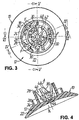
- FIGS. 1 to 6 show a block piece 10 for holding an optical workpiece, in particular a spectacle lens blank B (cf. FIGS. 7 and 8 ), for processing thereof.
- the block piece 10 comprises a basic body 12 that has a workpiece mounting face portion 14 against which the spectacle lens blank B can be blocked by means of a blocking material 16 (see FIG. 8 ), preferably a UV and/or VIS curable adhesive blocking composition as disclosed in document EP 2 011 604 A1 by the same applicant.
- the basic body 12 of the block piece 10 further comprises a clamping portion 18 via which the spectacle lens blank B blocked on the basic body 12 can be fixed in a machine or apparatus for processing (i.e. surfacing, coating, edging, tinting, cleaning, etc., as the case may be) of the spectacle lens blank B.
- the basic body 12 is injection molded as one piece from a plastic material that is capable of transmitting UV and VIS for the curing of the blocking material 16, and has a water absorption of less than 1% by weight at saturation, measured in accordance with DIN EN ISO 62:1999-08, method 1 (determination of water content absorbed after immersion in water at 23°C).
- a sealing coating 20 or tape, as the case may be
- the workpiece mounting face portion 14 on the front side of the block piece 10 is essentially spherical in shape and free of cut-outs to provide full support of the blocked spectacle lens blank B, nearly up to the edge E between the (in this instance convex) first or blocking face cx and the (in this instance concave) second face cc of the blocked spectacle lens blank B.
- the basic body 12 as a whole is formed to be free of undercuts and narrow channels in which liquids could be trapped.
- Adjoining the workpiece mounting face portion 14 of the basic body 12 on the outer circumference side is an essentially conical transition face 22 that leads to an essentially flat back face 24 on the back side of the block piece 10.
- the back face 24 of the basic body 12 is provided with two annular portions 26, 28 of different diameter that are concentrically arranged about a central axis A of the basic body 12, wherein the radial inner annular portion 28 protrudes beyond the radial outer annular portion 26 in the axial direction, as becomes apparent from FIGS. 1 , 4 to 6 and 8 in particular.
- a particular feature of the block piece 10 consists in the fact that the clamping portion 18 of the basic body 12 is adapted to be clamped by clamping forces that are directed essentially in a circumferential direction with respect to the central axis A of the basic body 12, or essentially in a tangential direction at a distance with respect to the central axis A of the basic body 12.
- the clamping portion 18 of the basic body 12 comprises at least one, in the examples of embodiment shown three radially extending clamping protrusions 30 that are non-uniformly distributed over the perimeter and, starting from the back face 24 of the basic body 12, bridge across the annular gap between the radial outer annular portion 26 and the radial inner annular portion 28.
- Each clamping protrusion 30 has two opposed side faces 32 each facing in the circumferential direction, for application of the above clamping forces that are schematically shown by arrows at F in FIGS. 1 to 3 and 7 . It is evident that the clamping forces F cancel out each other at the respective clamping protrusion 30, without passing through the whole basic body 12. Therefore, the clamping forces F do not bend the block piece 10 and accordingly do not distort the workpiece mounting face portion 14 and the spectacle lens blank B blocked thereon.
- clamping protrusions 30 each have a radial outer face 34 that is inclined with respect to the central axis A of the basic body 12, wherein the radial outer faces 34 together define an outer conical centering portion of the basic body 12, adjoining the outer circumference of the radial outer annular portion 26.
- the clamping protrusions 30 each have an axial end portion 36 facing away from the workpiece mounting face portion 14, wherein the axial end portions 36 each have a V-shaped cross-section seen in the radial direction to form a "roof"-shaped end, again for centering purposes in the assigned chuck (not shown) of the respective machining machine.
- the radial inner annular portion 28 of the basic body 12 starting from its free end, is provided with two cut-outs 38 for cylinder axis alignment of the block piece 10 on the spindle of the respective machining machine, corresponding to German standard DIN 58766, which cut-outs 38 are arranged on diametrically opposed sides with respect to the central axis A of the basic body 12, and taper essentially in a V-shaped manner towards the back face 24 of the basic body 12 to stop in the axial direction in front of the radial outer annular portion 26 as seen in a side view (cf. FIGS. 4 to 6 ).
- the radial inner annular portion 28 of the basic body 12 defines a central cylindrical blind hole 40 having an essentially flat bottom 42, wherein a plurality of stiffening ribs 44 extends between the bottom 42 and an inner circumference 46 of the radial inner annular portion 28.
- the stiffening ribs 44 each have a radial inner face 48 that is inclined with respect to the central axis A of the basic body 12, wherein the radial inner faces 48 together define an inner conical centering portion of the basic body 12.
- the outer circumference of the radial outer annular portion 26, the radial outer faces 34 and the axial end portions 36 of the clamping protrusions 30, the back face of the radial inner annular portion 28 and the radial inner faces 48 of the stiffening ribs 44 together define an "envelope" body, the geometry of which basically corresponds to the geometry of the block piece according to German standard DIN 58766, although the present block piece 10 due to its material and its "honeycombed” structure is much lighter than the standard block piece.
- This geometry of the basic body 12 together with the cut-outs 38 provided in the radial inner annular portion 28 makes the block piece 10 compatible with standard chuck situations.
- the back side of the basic body 12 of this block piece 10 differs from the back side of the basic body 12 of the above block piece only in that the conical transition face 22 is provided with a plurality of recesses 50 that are uniformly distributed over the circumference, and serve to provide for essentially uniform wall thicknesses throughout the basic body 12 thereby avoiding shrinkage related problems in the preferred plastic injection molding process.
- the back side of this block piece 10 could also be formed different, for instance as disclosed in the generic document EP 1 593 458 A2 .
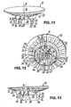
- the workpiece mounting face portion 14 that is essentially spherical in shape again, is tilted or shifted by a predetermined amount with respect to the central axis A of the basic body 12 in order to provide a defined amount of prism in the block piece 10.
- the workpiece mounting face portion 14 is tilted by 2 degrees with respect to the central axis A.
- Such prism in the geometry of the block piece 10 can be used as explained in great detail in the introductory portion of the description to which reference is made in this regard at this point.
- FIG. 16 shows a plan view of a spectacle lens blank B with its vertical axis 52 and its horizontal axis 54 corresponding to the mounting axes of the finished spectacle lens in a spectacle frame. It will be assumed that the second face cc of the spectacle lens blank B must be shaped, in relation to the blocking face cx, so as to have a predetermined prism value, measured in prismatic diopters, with a predetermined orientation of the prism axis 56 with respect to, e.g., the horizontal axis 54.
- the spectacle lens has to be given a toric configuration with a cylinder axis 58 having a predetermined orientation with respect to, e.g., the horizontal axis 54, which orientation, as a rule, differs from the orientation of the prism axis 56.
- the cylinder axis 58 is normally aligned with the cut-outs 38 in the block piece 10. This obviously cannot be done with the present PBP block piece 10. It is clear that, if a defined amount of prism shall be generated in the spectacle lens, the spectacle lens blank B must be blocked with its prism axis 56 aligned with the prism direction in the PBP block piece 10.
- the prism in the workpiece mounting face portion 14 is oriented along the line XV-XV in FIG. 14 , which in turn runs at right angles with respect to the cut-outs 38 in the basic body 12 (cf. FIG. 15 ) .
- this could be different as long as there is a defined relation between the prism orientation of the workpiece mounting face portion 14 and the block piece mounting features on the back side of the block piece 10.
- FIG. 17 shows by means of a flow chart the main process steps of a method for manufacturing spectacle lenses according to a prescription with the aid of a block piece 10 as described above.
- this method comprises the steps of: (i) blocking a spectacle lens blank B with its blocking face cx on the workpiece mounting face portion 14 of the block piece 10 with the aid of a blocking material 16, (ii) processing the blocked spectacle lens blank B on the second face cc and optionally the edge E to obtain a processed spectacle lens, and (iii) deblocking the processed spectacle lens from the block piece 10, with the characterizing feature that the spectacle lens blank B remains on the proposed block piece 10 throughout the whole processing stage or step (ii).
- the latter stage or step generally comprises the following substeps: "Generating", i.e.
- a top coating TC such as a hydrophobic and/or oleophobic and/or dust repelling coating on the second face cc; and (optionally) edging of the blocked spectacle lens blank B to give the edge E the required geometry so that the processed spectacle lens, after deblocking and final inspection, is ready for insertion into a spectacle frame or a spectacle holder. Since the single processing substeps and the equipment used in those are well known to the person skilled in the art further explanations in this respect are not required at this point.
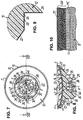
- the blocking face cx of the spectacle lens blank B is fully finished prior to the above blocking step (i), including hard coating HC, antireflection coating AR and optionally top coating TC such as (super) hydrophobic and/or oleophobic and/or dust repelling coating, i.e. the blocking face cx of the spectacle lens blank B would carry the multilayer system as shown in FIG. 10 prior to blocking.
Abstract
Description
- The present invention generally relates to a workpiece support block ("block piece") for supporting an optical workpiece during the processing thereof. In particular, the invention relates to a block piece for holding a spectacle lens for processing thereof according to the preamble portion of claim 1, as used in prescription workshops in masses, that is to say production workshops for manufacturing individual spectacle lenses from customary materials (mineral glass, polycarbonate, PMMA, CR 39, HI index, etc.) according to a prescription. The invention also concerns a method for manufacturing spectacle lenses according to a prescription, as outlined in the preamble portion of claim 11.
- An ophthalmic lens blank generally has a first face with a predetermined curvature and a second face, opposite the first face on which a desired surface contour is generated by a machining process. The overall process is generally referred to as "lens surfacing" and the overall object is to yield a finished spectacle lens so that the first and second face curvatures cooperate to yield desired optical properties. In addition to this the first and/or second faces of the lens are usually coated to provide the finished spectacle lens with an enhanced ability to resist scratching (by means of a "hard coating"), with a low residual reflection and a desired color (by means of an "antireflection coating"), and/or with certain surface properties such as hydrophobic, oleophobic and dust repelling properties (by means of a "top coating"). Usually also a further machining process takes place (the so-called "edging"), the aim of which is to finish-machine the edge of the spectacle lens in such a way that the spectacle lens may be inserted into a spectacle frame. In all these process steps the spectacle lens (blank) must somehow be held in the machining machine (s) and coating apparatus respectively.
- In more detail, hitherto the following main process steps are usually carried out in prescription workshops: Firstly, a suitable right and/or left ophthalmic lens blank is removed from a semifinished product store. The term "semifinished" is used to mean that the spectacle lens blanks, which are usually round or oval in plan view and have not yet been edged, have already been molded, machined or in another way contoured (surfaced) on one of their two optically active faces only. The spectacle lens blanks are then prepared for the blocking operation, namely by applying a suitable protective film or a suitable protective lacquer to protect the optically active face which has already been machined or contoured, i.e. the first face or blocking face.
- The so-called "blocking" of the ophthalmic lens blanks then takes place. During this, the spectacle lens blank is joined to a suitable block piece, for example a lens block according to German standard DIN 58766 or document
EP 1 593 458 A2 . To this end, the block piece is firstly brought into a predefined position with respect to the protected first face of the spectacle lens blank, and then in this position the space between block piece and spectacle lens blank is filled with a molten material (normally a metal alloy or wax) or an adhesive composition that is curable, e.g., by UV or visible light, as described in documentEP 2 011 604 A1 by the same applicant for instance. Once this material has solidified or cured, the block piece forms a holder or support for machining the second face of the spectacle lens blank. The block piece is grasped by a chuck or other suitable coupling means during lens generation to provide in particular secure mounting to the profiling machine while avoiding damage to the lens. - Lens surfacing is carried out then using profiling machines which typically have a cutter of some type that is moved across the second face of the ophthalmic lens blank to give the second face its macrogeometry according to the prescription. The spectacle lens blank may be stationary or rotating during the cutting operation, depending on the particular profiling machine which is being used. Typical machining processes for surfacing spectacle lenses include single point diamond turning (as the presently preferred fine cutting process for plastic materials and described in, e.g., document
EP 1 719 585 A2 by the same applicant), diamond tool fly-cutting, milling (as the presently preferred rough cutting process for plastic materials and described in, e.g., documentEP 0 758 571 A1 by the same applicant), and grinding processes, applied depending on the lens material. - Usually fine machining of the ophthalmic lenses then takes place, in which the pre-machined second face of the respective spectacle lens blank is given the desired microgeometry, as described, e.g., in documents
EP 1 473 116 A1 andEP 1 698 432 A2 by the same applicant. Depending on inter alia the material of the spectacle lenses, the fine machining process is divided into a fine grinding operation and a subsequent polishing operation, or includes only a polishing operation if a polishable second face has already been produced during the pre-machining stage. - Only after the polishing operation is the ophthalmic lens blank separated from the lens block ("deblocking") before cleaning steps are carried out. Then the coating process(es) take(s) place that, depending on among other things the material of the lens blank, may include spin (or dip) coating of the deblocked spectacle lens blank so as to provide at least the second face of the lens blank with a hard coating or the like, as described, e.g., in document
US 2008 0035053 A1 , wherein the spectacle lens blank is held in the spin coating apparatus by means of a lens holder that has a suction cup for instance. - At any rate coating includes vacuum coating of the deblocked spectacle lens blank so as to provide at least the second face of the lens blank with an antireflection coating and optionally a top coating serving the above mentioned purpose(s). In the vacuum coating process the spectacle lens blank is clamped to a substrate carrier of a rotary carrier device that is located in a vacuum chamber in a vertically spaced relation with respect to an evaporation source for emitting a vapor stream onto the lens blank mounted on the substrate carrier, as described, e.g., in document
EP 0 806 492 A1 . - After the coating step(s) the ophthalmic lens blank usually is edged so that the spectacle lens can be inserted into a spectacle frame. To this end, the coated spectacle lens blank is blocked again, at this time however to a different, smaller block piece by means of an adhesive film portion for instance, as described, e.g., in document
EP 1 243 381 A2 by the same applicant. The edging process may also include the forming of bores, grooves, channels and/or bevels corresponding to the respective mounting requirements in the edge area of the spectacle lens, as described, e.g., in documentEP 1 243 380 A2 by the same applicant. - Finally, after edging and a further deblocking step the spectacle lens is cleaned again and ready for inspection and insertion into / mounting to the spectacle frame.
- One disadvantage of the conventional overall process as outlined above consists in the fact that the spectacle lens blank needs to be deblocked after surfacing prior to coating, and then again blocked after coating prior to edging, for this requiring manual operations that are time-consuming and labor-intensive.
- Another problem with the conventional process in prescription workshops is associated with in particular the single point diamond turning as the presently preferred fine cutting process for spectacle lens blanks made from plastic materials. This surfacing process as such is susceptible to small, but unacceptable errors at the center of rotation of the lens blank that are typically caused by errors of machine and tool calibration, as explained in great detail in document
EP 1 719 584 A1 by the same applicant. This, coupled to certain limitations of the subsequent (flexible) polishing process, where it can be difficult to totally "clean up" or remove such center errors, have led to certain limitations in the amount of prism (i.e. surface tilt or shift with respect to the axis of rotation) permissible to cut and polish in such combined surfacing process. Experiments have shown that it can be relatively easy to cut and polish surfaces having 2 to 3 degrees of prism at the center with accurate centers, however greater amounts of prism at the center can pose problems. - A known method (see, e.g., document
US 6 913 356 B2 ) for fitting a block piece to a semifinished blank of an ophthalmic lens intended to have a particular prism generally consists of positioning the lens blank on a fixed base, in a centered and angularly defined manner, so that the finished face of the lens blank bears conjointly on a plurality of bearing points of the base, defining an orientation of the block piece relative to the lens blank, orienting the block piece in the defined manner, and fixing the block piece to the finished face while maintaining orientation, by means of a castable low melting point metal alloy as the blocking material. - Once the lens blank is blocked on the block piece with the predetermined amount of prism that the spectacle lens shall have after surfacing, there is no need to generate, i.e. cut any prism during the surfacing process. However, one disadvantage of this known approach consists in the fact that, if the lens blank is blocked with a greater amount of prism, say 7 or 8 degrees of prism, the thickness of the wedge-shaped layer of blocking material between lens blank and block piece strongly varies along the prism axis. This gives rise to a different amount of shrinkage of the blocking material in the thickness direction along the prism axis when it solidifies (or cures if an adhesive composition would be used), which shrinkage in turn may bend/distort (or even shift with respect to the block piece) the blocked lens blank - as described in document
EP 2 011 604 A1 by the same applicant - so that, again, the curve which is cut into the surface of the lens blank may become distorted when the lens blank is deblocked from the block piece and resumes its natural shape. For this reason the amount of prism permissible to be blocked is also limited in the known approach. - Document
WO 2007/017385 A2 forms the preamble portion of claim 1. - The object of the present invention is to provide a block piece for holding an optical workpiece, in particular a spectacle lens, for processing thereof, which block piece serves to solve the drawbacks previously cited of the techniques known in the art and enables in particular spectacle lenses with high optical qualities to be produced more quickly and at lower cost, without restrictions as to the lens geometries usually processed in prescription workshops. The object of the invention further encompasses the provision of a method for manufacturing spectacle lenses according to a prescription that serves the above purposes.
- The above object is solved by the features specified in claim 1 and 11, respectively. Advantageous and appropriate developments of the invention form the subject matter of claims 2 to 10, 12 and 13.
- According to the present invention there is provided a block piece for holding an optical workpiece, in particular a spectacle lens, for processing thereof, comprising a basic body that is injection molded as one piece from a plastic material and has a central axis, a workpiece mounting face portion, which is essentially spherical in shape, and against which the workpiece can be blocked by means of a blocking material, and a clamping portion via which the workpiece blocked on the basic body can be fixed in a machine or apparatus for processing of the workpiece; wherein the workpiece mounting face portion is free of cut-outs to provide full support of the blocked workpiece, and tilted or shifted by a predetermined amount with respect to the central axis of the basic body in order to provide a defined amount of prism in the block piece, wherein said plastic material of the basic body is capable of transmitting UV and VIS for curing of said blocking material, and has a water absorption of less than 1% by weight at saturation, measured in accordance with DIN EN ISO 62:1999-08, method 1.
- For instance 2 degrees of prism could be provided in the block piece by tilting the workpiece mounting face portion of the block piece by 2 degrees with respect to the central axis of the basic body. All lens blanks subsequently blocked on these "pre-blocked prism" (PBP) block pieces would therefore start with 2 degrees of prism (assuming the lens blank is blocked on the respective PBP block piece in such orientation that the prism axis of the spectacle lens to be manufactured according to the prescription is aligned with the prism direction of the PBP block piece). Knowing the orientation of the prism direction of the PBP block piece relative to the block mounting features (datums) that are usually defined by the geometry of the clamping portion of the block piece, one can calculate to increase or decrease the amount of prism cut in the final lens by adding to or subtracting from the prism in the PBP block piece. This can essentially be used to effectively decrease the total prism to be surfaced by the prism angle in the PBP block piece, in order to address the above described limitations of a combined surfacing process in which a spectacle lens blank made from a plastic material is fine cut by single point diamond turning and then polished with the aid of a flexible polishing tool.
- If for instance the maximum amount of prism that can safely be cut with no excessive center defect in such combined surfacing process would be 3 degrees, while the maximum prism that should be supported in the surfacing process would be 5.5 degrees, the PBP block piece would be provided with 2.5 degrees of pre-blocked prism. Thus, all lens blanks blocked on these PBP block pieces would have 2.5 degrees of prism tilt in a known direction. Then, this 2.5 degrees of prism could be cancelled out by cutting -2.5 degrees of prism to end up with a lens of 0 degrees of prism, or prism could be added to the 2.5 degrees of pre-blocked prism by cutting up to 3 degrees of prism to obtain a total of 5.5 degrees of prism, i.e. without cutting more than the above limit of 3 degrees of prism. As a result, any prism angle in between +/- 3 degrees could safely be cut to obtain between 0 and 5.5 degrees of prism in the final lens. In the prescription workshop the lens layout calculation program would then need to keep track of the placement of the cylinder axis according to the prescription relative to the prism axis as the PBP block piece has a fixed prism orientation, but a variable cylinder axis orientation relative to the block reference geometry (unlike the conventional surfacing technology where the cylinder axis is aligned in a fixed orientation relative to the block reference geometry, and the prism alignment is variable). This implies that such a PBP block piece is primarily used for "flexible" polishing as opposed to conventional hard lap polishing requiring a fixed cylinder axis orientation.
- In addition, such a PBP block piece also addresses the above described problems that are associated with a strong thickness variation in any wedge-shaped layer of blocking material between lens blank and block piece. It is evident that, even if the final lens shall have a greater amount of prism, say, e.g., the above 5.5 degrees of prism, with the PBP block piece the thickness of the layer of blocking material along the prism axis does not vary as strongly as would be the case if a block piece without prism in the workpiece mounting face portion was used. In the example the wedge angle between lens blank and block piece would only amount to 3 degrees with the PBP block piece having 2.5 degrees of prism in the workpiece mounting face portion, whereas it would amount to 5.5 degrees without prism in the workpiece mounting face portion of the block piece. Consequently also the risk that any shrinkage of the blocking material upon solidifying or curing will distort the blocked lens blank and/or change the desired prism is minimized by using the PBP block piece.
- In this connection an advantageous secondary effect consists in the fact that, since the gap between lens blank and block piece that must be filled with the blocking material is minimized by using the PBP block piece, also the amount of blocking material necessary for this purpose is minimized, again helping to reduce costs in prescription workshops.
- In a preferred embodiment of the block piece the clamping portion is adapted to be clamped by clamping forces that are directed essentially in a circumferential direction with respect to the central axis of the basic body, or essentially in a tangential direction at a distance with respect to the central axis of the basic body.
- The main effect of this block piece design is that, even if the block piece would be made from a rather soft plastic material, the clamping forces that are exerted on the block piece in the circumferential or tangential direction by a correspondingly adapted chuck in the surfacing or edging machine(s) do not "travel" or pass through the whole block piece as in the conventional case where a radial compression force is applied to the clamping portion of the block piece, thereby avoiding any excessive deformation of the block piece that could transfer to the workpiece blocked on the block piece and cause any undesirable distortion of the finished workpiece geometry. Again, this helps to manufacture in, e.g., prescription workshops spectacle lenses with high optical qualities.
- In one embodiment the clamping portion of the basic body may comprise at least one radially extending clamping protrusion that has two opposed side faces each facing in the circumferential direction, for application of the clamping forces. Preferably the clamping portion of the basic body comprises three radially extending clamping protrusions that are distributed over the perimeter. This could be a uniform distribution; preferred however would be a non-uniform distribution of the clamping protrusions over the perimeter so that the clamping protrusions can also serve to rotationally orient the block piece in the machining machine(s).
- It is further preferred for the clamping protrusions of the clamping portion to each have a radial outer face that is inclined with respect to the central axis of the basic body so that the radial outer faces together define an outer conical centering portion of the basic body, corresponding to German standard DIN 58766, for centering the block piece in the assigned chuck of the respective machining machine.
- Further, the clamping protrusions preferably each have an axial end portion facing away from the workpiece mounting face portion, wherein the axial end portions each have a V-shaped cross-section seen in the radial direction, again serving to facilitate the mounting of the block piece in the assigned chuck of the respective machining machine.
- In a preferred embodiment of the block piece, on a side facing away from the workpiece mounting face portion, the basic body comprises two annular portions of different diameter that are concentrically arranged about the central axis of the basic body, the radial inner annular portion protruding beyond the radial outer annular portion in the axial direction, wherein the clamping protrusions extend between the annular portions. Such design is particularly advantageous when the block piece is injection molded from a plastic material since it serves to provide for essentially uniform wall thicknesses throughout the basic body thereby avoiding shrinkage related problems in the injection molding process. In this embodiment the clamping protrusions, by extending between the annular portions or bridging across the annular gap therebetween, advantageously also serve to stiffen or reinforce the basic body of the block piece. A further advantage of this embodiment is that the block piece, owing to its "honeycombed" structure already, has a low weight so that there are lower moving masses on the workpiece side during machining of the blocked workpiece compared to conventional block pieces, e.g., the block piece according to German standard DIN 58766.
- In this instance the radial inner annular portion of the basic body may be provided with two cut-outs that are arranged on diametrically opposed sides with respect to the central axis of the basic body, for cylinder axis alignment of the block piece on a spindle of a machining machine, corresponding to German standard DIN 58766.
- In this embodiment the radial inner annular portion of the basic body may further define a central cylindrical blind hole having a flat bottom, wherein a plurality of stiffening ribs extends between the bottom and an inner circumference of the radial inner annular portion. In this instance the stiffening ribs preferably each have a radial inner face that is inclined with respect to the central axis of the basic body, wherein the radial inner faces together define an inner conical centering portion of the basic body, again corresponding to German standard DIN 58766, so that the block piece as a whole is compatible with standard chuck situations, including the reception in handling devices and in job trays (e.g. such as described in German standard DIN 58763).
- The invention also provides for a method for manufacturing spectacle lenses according to a prescription, comprising the steps of: (i) blocking a lens blank with a blocking face on a workpiece mounting face portion of a block piece with the aid of a blocking material, the lens blank having a second face, opposite the blocking face, and an edge between the blocking face and the second face, (ii) processing the blocked lens blank on the second face and, if required, the edge to obtain a processed lens, and (iii) deblocking the processed lens from the block piece; wherein one and the same block piece as described above is used on which the blocked lens blank remains throughout step (ii).
- Since the spectacle lens blank remains on the block piece throughout the whole processing step the latter can be carried out faster and more efficient with less handling effort as compared to the conventional approach where the lens blank needs to be deblocked and blocked again in the processing stage. This reduces the manufacturing costs and even allows for more automation in the prescription workshops. The approach according to the invention also serves to ensure the production of spectacle lenses with high optical qualities because one and the same geometrical relation between lens blank and block piece is maintained throughout the whole processing stage, thus any errors that are consequential on the conventional re-blocking approach where the orientation of the lens blank relative to the assigned different block pieces may unintentionally change upon re-blocking are avoided. Further, as the lens blank is always held on the block piece as standardized interface and handling means during the processing stage the risk that any operator unintentionally touches the lens blank - thereby possibly causing problems in a coating substep - is reduced. A further advantage consists in the fact that all production information can be kept on the block piece, for instance by means of a "transponder" integrated in or fixed to the block piece, as proposed in the generic document
EP 1 593 458 A2 , which offers full tracking possibility throughout the whole process. - Continuing the concept of the invention, the above processing step (ii) may comprise the following substeps: machining of the blocked lens blank to give the second face a macrogeometry according to the prescription; fine machining of the blocked lens blank to give the second face the required microgeometry; cleaning the blocked lens blank that has been machined and fine machined; if required, spin or dip coating of the blocked lens blank in order to provide the second face with a hard coating, or a primer, or a primer and a hard coating; vacuum coating of the blocked lens blank to provide an antireflection coating and, if required, a top coating such as hydrophobic and/or oleophobic and/or dust repelling coating on the second face; and, if required, edging of the blocked lens blank to give the edge the required geometry so that the processed lens is ready for insertion into a spectacle frame or a spectacle holder. Since there is no deblocking step in the processing stage any more, some processing substeps could even be carried out in a - as compared to the conventional time sequence - different sequence where a certain fixed sequence is not necessary from a product point of view, in particular all machining operations including edging could be carried out prior to the coating process(es) if desired or required.
- Finally, it is preferred for the blocking face of the lens blank to be fully finished prior to the above blocking step (i), including hard coating, antireflection coating and, if required, top coating such as hydrophobic and/or oleophobic and/or dust repelling coating. In this instance the blocked spectacle lens blank could advantageously be shipped from the lens manufacturer to the prescription workshop where only the second face and, if required, the edge of the lens blank would need to be processed to obtain a spectacle lens ready for insertion into / mounting to the spectacle frame, wherein the first face of the lens blank would be protected by the block piece until the finished spectacle lens is deblocked. This approach would also minimize the production efforts in the prescription workshop.
- Further effects and advantages of the proposed block piece and method for manufacturing spectacle lenses according to a prescription will become apparent to the skilled person from the following description of currently preferred examples of embodiment of the invention.
- Hereinbelow, the invention will be explained in more detail on the basis of preferred examples of embodiment and with reference to the appended, partially schematic drawings. In the drawings:
- FIG. 1
- shows a perspective view of a block piece, not according to the invention, obliquely from the front/top, which is shown on an enlarged scale compared to the actual size;
- FIG. 2
- shows a perspective view of the block piece of
FIG. 1 obliquely from behind/below; - FIG. 3
- shows a view from below of the block piece of
FIG. 1 ; - FIG. 4
- shows a sectional view of the block piece of
FIG. 1 along the section line IV-IV inFIG. 3 ; - FIG. 5
- shows a sectional view of the block piece of
FIG. 1 along the section line V-V inFIG. 3 ; - FIG. 6
- shows a sectional view of the block piece of
FIG. 1 along the section line VI-VI inFIG. 3 ; - FIG. 7
- shows a view from below of the block piece of
FIG. 1 on a reduced scale compared to the previous figures, with a spectacle lens blank as optical workpiece blocked thereon by means of an adhesive composition; - FIG. 8
- shows a sectional view of the block piece and of the spectacle lens blank of
FIG. 7 blocked thereon, along the section line VIII-VIII inFIG. 7 ; - FIG. 9
- is an enlarged view of detail IX in
FIG. 8 , illustrating in section a coating that may be applied to the block piece for sealing it; - FIG. 10
- is an enlarged view of detail X in
FIG. 8 , illustrating an example for a coating that may be applied to the concave and/or convex face of the spectacle lens blank; - FIG. 11
- shows a perspective view of a block piece, according to the invention, obliquely from the front/top, which is shown on a scale that nearly corresponds to the actual size;
- FIG. 12
- shows a perspective view of the block piece of
FIG. 11 obliquely from behind/below; - FIG. 13
- shows a side view of the block piece of
FIG. 11 ; - FIG. 14
- shows a view from below of the block piece of
FIG. 11 ; - FIG. 15
- is a sectional view of the block piece of
FIG. 11 along the section line XV-XV inFIG. 14 , illustrating how the essentially spherical workpiece mounting face portion of the block piece is tilted with respect to the central axis of the block piece to provide a predetermined amount of prism in the block piece; - FIG. 16
- shows a plan view of a spectacle lens blank with its horizontal and vertical mounting axes, a prescribed prism axis and a prescribed cylinder axis; and
- FIG. 17
- is a flow chart illustrating among other things the main process steps of a method for manufacturing spectacle lenses according to a prescription in accordance with the present invention.
-
FIGS. 1 to 6 show ablock piece 10 for holding an optical workpiece, in particular a spectacle lens blank B (cf.FIGS. 7 and 8 ), for processing thereof. Theblock piece 10 comprises abasic body 12 that has a workpiece mountingface portion 14 against which the spectacle lens blank B can be blocked by means of a blocking material 16 (seeFIG. 8 ), preferably a UV and/or VIS curable adhesive blocking composition as disclosed in documentEP 2 011 604 A1 by the same applicant. Thebasic body 12 of theblock piece 10 further comprises a clampingportion 18 via which the spectacle lens blank B blocked on thebasic body 12 can be fixed in a machine or apparatus for processing (i.e. surfacing, coating, edging, tinting, cleaning, etc., as the case may be) of the spectacle lens blank B. - In the examples of embodiment shown the
basic body 12 is injection molded as one piece from a plastic material that is capable of transmitting UV and VIS for the curing of the blockingmaterial 16, and has a water absorption of less than 1% by weight at saturation, measured in accordance with DIN EN ISO 62:1999-08, method 1 (determination of water content absorbed after immersion in water at 23°C). OnlyFIGS. 8 and 9 illustrate that thebasic body 12 could also be sealed by a sealing coating 20 (or tape, as the case may be) which at least partially covers the outer surface of thebasic body 12 so as to prevent or at least reduce outgassing of any water moisture trapped within the material of thebasic body 12 under vacuum conditions. It is clear thatsuch sealing coating 20, if present, should cover those surface portions of thebasic body 12 that are exposed to the "environment" in the vacuum chamber of the apparatus for coating the spectacle lens blank B. - As can be seen in particular from
FIGS. 4 to 6 and8 , the workpiece mountingface portion 14 on the front side of theblock piece 10 is essentially spherical in shape and free of cut-outs to provide full support of the blocked spectacle lens blank B, nearly up to the edge E between the (in this instance convex) first or blocking face cx and the (in this instance concave) second face cc of the blocked spectacle lens blank B. It can also be seen from these figures that thebasic body 12 as a whole is formed to be free of undercuts and narrow channels in which liquids could be trapped. - Adjoining the workpiece mounting
face portion 14 of thebasic body 12 on the outer circumference side is an essentially conical transition face 22 that leads to an essentiallyflat back face 24 on the back side of theblock piece 10. Starting from theback face 24 of thebasic body 12 the latter is provided with twoannular portions basic body 12, wherein the radial innerannular portion 28 protrudes beyond the radial outerannular portion 26 in the axial direction, as becomes apparent fromFIGS. 1 ,4 to 6 and8 in particular. - A particular feature of the
block piece 10 consists in the fact that the clampingportion 18 of thebasic body 12 is adapted to be clamped by clamping forces that are directed essentially in a circumferential direction with respect to the central axis A of thebasic body 12, or essentially in a tangential direction at a distance with respect to the central axis A of thebasic body 12. To this end the clampingportion 18 of thebasic body 12 comprises at least one, in the examples of embodiment shown three radially extending clampingprotrusions 30 that are non-uniformly distributed over the perimeter and, starting from theback face 24 of thebasic body 12, bridge across the annular gap between the radial outerannular portion 26 and the radial innerannular portion 28. Each clampingprotrusion 30 has two opposed side faces 32 each facing in the circumferential direction, for application of the above clamping forces that are schematically shown by arrows at F inFIGS. 1 to 3 and7 . It is evident that the clamping forces F cancel out each other at therespective clamping protrusion 30, without passing through the wholebasic body 12. Therefore, the clamping forces F do not bend theblock piece 10 and accordingly do not distort the workpiece mountingface portion 14 and the spectacle lens blank B blocked thereon. - Further, the clamping
protrusions 30 each have a radialouter face 34 that is inclined with respect to the central axis A of thebasic body 12, wherein the radial outer faces 34 together define an outer conical centering portion of thebasic body 12, adjoining the outer circumference of the radial outerannular portion 26. Finally, the clampingprotrusions 30 each have anaxial end portion 36 facing away from the workpiece mountingface portion 14, wherein theaxial end portions 36 each have a V-shaped cross-section seen in the radial direction to form a "roof"-shaped end, again for centering purposes in the assigned chuck (not shown) of the respective machining machine. - As can best be seen in
FIGS. 1, 2 ,4 and6 , the radial innerannular portion 28 of thebasic body 12, starting from its free end, is provided with two cut-outs 38 for cylinder axis alignment of theblock piece 10 on the spindle of the respective machining machine, corresponding to German standard DIN 58766, which cut-outs 38 are arranged on diametrically opposed sides with respect to the central axis A of thebasic body 12, and taper essentially in a V-shaped manner towards theback face 24 of thebasic body 12 to stop in the axial direction in front of the radial outerannular portion 26 as seen in a side view (cf.FIGS. 4 to 6 ). - Furthermore, the radial inner
annular portion 28 of thebasic body 12 defines a central cylindricalblind hole 40 having an essentially flat bottom 42, wherein a plurality of stiffeningribs 44 extends between the bottom 42 and aninner circumference 46 of the radial innerannular portion 28. The stiffeningribs 44 each have a radialinner face 48 that is inclined with respect to the central axis A of thebasic body 12, wherein the radial inner faces 48 together define an inner conical centering portion of thebasic body 12. As a result, when thebasic body 12 is rotated about the central axis A, the outer circumference of the radial outerannular portion 26, the radial outer faces 34 and theaxial end portions 36 of the clampingprotrusions 30, the back face of the radial innerannular portion 28 and the radial inner faces 48 of the stiffeningribs 44 together define an "envelope" body, the geometry of which basically corresponds to the geometry of the block piece according to German standard DIN 58766, although thepresent block piece 10 due to its material and its "honeycombed" structure is much lighter than the standard block piece. This geometry of thebasic body 12 together with the cut-outs 38 provided in the radial innerannular portion 28 makes theblock piece 10 compatible with standard chuck situations. - With regard to the actual blocking operation, the result of which is shown in
FIGS. 7 and 8 , explicit reference is made to documentEP 2 011 604 A1 by the same applicant, disclosing a blocking apparatus that could be used and the currently preferred approach for blocking. - The following describes the
block piece 10 according to the invention with reference toFIGS. 11 to 16 only insofar as it differs from the above block piece whereby the same reference numbers identify the same or equivalent components or parts. - The back side of the
basic body 12 of thisblock piece 10 differs from the back side of thebasic body 12 of the above block piece only in that theconical transition face 22 is provided with a plurality ofrecesses 50 that are uniformly distributed over the circumference, and serve to provide for essentially uniform wall thicknesses throughout thebasic body 12 thereby avoiding shrinkage related problems in the preferred plastic injection molding process. Basically, however, the back side of thisblock piece 10 could also be formed different, for instance as disclosed in the generic documentEP 1 593 458 A2 . - The more important difference is on the front side of the
basic body 12. As can be seen best inFIGS. 13 and15 , the workpiece mountingface portion 14 that is essentially spherical in shape again, is tilted or shifted by a predetermined amount with respect to the central axis A of thebasic body 12 in order to provide a defined amount of prism in theblock piece 10. In the example of embodiment shown the workpiece mountingface portion 14 is tilted by 2 degrees with respect to the central axis A. Such prism in the geometry of theblock piece 10 can be used as explained in great detail in the introductory portion of the description to which reference is made in this regard at this point. - As to the actual blocking operation, which basically can be carried out as described in document
EP 2 011 604 A1 by the same applicant, it should be pointed out here that theblock piece 10 with inherent prism ("pre-blocked prism" (PBP) block piece) needs a different orientation with respect to the lens blank B as compared to the conventional approach, as will be explained with reference toFIG. 16 . -
FIG. 16 shows a plan view of a spectacle lens blank B with itsvertical axis 52 and itshorizontal axis 54 corresponding to the mounting axes of the finished spectacle lens in a spectacle frame. It will be assumed that the second face cc of the spectacle lens blank B must be shaped, in relation to the blocking face cx, so as to have a predetermined prism value, measured in prismatic diopters, with a predetermined orientation of theprism axis 56 with respect to, e.g., thehorizontal axis 54. Moreover, it will be assumed that the spectacle lens has to be given a toric configuration with acylinder axis 58 having a predetermined orientation with respect to, e.g., thehorizontal axis 54, which orientation, as a rule, differs from the orientation of theprism axis 56. Now, in the conventional blocking approach, thecylinder axis 58 is normally aligned with the cut-outs 38 in theblock piece 10. This obviously cannot be done with the presentPBP block piece 10. It is clear that, if a defined amount of prism shall be generated in the spectacle lens, the spectacle lens blank B must be blocked with itsprism axis 56 aligned with the prism direction in thePBP block piece 10. In the example of embodiment shown the prism in the workpiece mountingface portion 14 is oriented along the line XV-XV inFIG. 14 , which in turn runs at right angles with respect to the cut-outs 38 in the basic body 12 (cf.FIG. 15 ) . However, this could be different as long as there is a defined relation between the prism orientation of the workpiece mountingface portion 14 and the block piece mounting features on the back side of theblock piece 10. - Finally,
FIG. 17 shows by means of a flow chart the main process steps of a method for manufacturing spectacle lenses according to a prescription with the aid of ablock piece 10 as described above. - Basically, this method comprises the steps of: (i) blocking a spectacle lens blank B with its blocking face cx on the workpiece mounting
face portion 14 of theblock piece 10 with the aid of a blockingmaterial 16, (ii) processing the blocked spectacle lens blank B on the second face cc and optionally the edge E to obtain a processed spectacle lens, and (iii) deblocking the processed spectacle lens from theblock piece 10, with the characterizing feature that the spectacle lens blank B remains on the proposedblock piece 10 throughout the whole processing stage or step (ii). According toFIG. 17 , the latter stage or step generally comprises the following substeps: "Generating", i.e. machining of the blocked spectacle lens blank B to give the second face cc a macrogeometry according to the prescription; "Polishing", i.e. fine machining of the blocked spectacle lens blank B to give the second face cc the required microgeometry; cleaning the blocked spectacle lens blank B that has been machined and fine machined; (optionally) spin (or dip) coating of the blocked spectacle lens blank B in order to provide the second face cc with a hard coating HC (seeFIG. 10 ), or a primer, or a primer and a hard coating; vacuum coating of the blocked spectacle lens blank B to provide an antireflection coating AR (normally consisting of four to seven layers made up of two to four materials with different refractive indices, as illustrated inFIG. 10 ) and (optionally) a top coating TC (cf. againFIG. 10 ) such as a hydrophobic and/or oleophobic and/or dust repelling coating on the second face cc; and (optionally) edging of the blocked spectacle lens blank B to give the edge E the required geometry so that the processed spectacle lens, after deblocking and final inspection, is ready for insertion into a spectacle frame or a spectacle holder. Since the single processing substeps and the equipment used in those are well known to the person skilled in the art further explanations in this respect are not required at this point. - As can further be seen from
FIG. 17 , for the reasons indicated in the introductory portion of the description already, it is preferred that the blocking face cx of the spectacle lens blank B is fully finished prior to the above blocking step (i), including hard coating HC, antireflection coating AR and optionally top coating TC such as (super) hydrophobic and/or oleophobic and/or dust repelling coating, i.e. the blocking face cx of the spectacle lens blank B would carry the multilayer system as shown inFIG. 10 prior to blocking. -
- 10
- block piece
- 12
- basic body
- 14
- workpiece mounting face portion
- 16
- blocking material
- 18
- clamping portion
- 20
- sealing coating
- 22
- conical transition face
- 24
- back face
- 26
- radial outer annular portion
- 28
- radial inner annular portion
- 30
- clamping protrusion
- 32
- side face
- 34
- radial outer face
- 36
- axial end portion
- 38
- cut-out
- 40
- blind hole
- 42
- bottom
- 44
- stiffening rib
- 46
- inner circumference
- 48
- radial inner face
- 50
- recess
- 52
- vertical axis
- 54
- horizontal axis
- 56
- prism axis
- 58
- cylinder axis
- A
- central axis
- B
- spectacle lens blank
- E
- edge of spectacle lens blank
- F
- clamping force
- cc
- second face of spectacle lens blank
- cx
- blocking face of spectacle lens blank
- AR
- antireflection coating
- HC
- hard coating
- TC
- top coating
Claims (13)
- A block piece (10) for holding an optical workpiece (B), in particular a spectacle lens, for processing thereof, comprising:a basic body (12) injection molded as one piece from a plastic material and havinga central axis (A),a workpiece mounting face portion (14), which is essentially spherical in shape, and against which the workpiece (B) can be blocked by means of a blocking material (16), anda clamping portion (18) via which the workpiece (B) blocked on said basic body (12) can be fixed in a machine or apparatus for processing of the workpiece (B);wherein said workpiece mounting face portion (14) is free of cut-outs to provide full support of the blocked workpiece (B), and tilted or shifted by a predetermined amount with respect to the central axis (A) of said basic body (12) in order to provide a defined amount of prism in the block piece (10), characterized in that said plastic material of said basic body (12) is capable of transmitting UV and VIS for curing of said blocking material (16), and has a water absorption of less than 1% by weight at saturation, measured in accordance with DIN EN ISO 62:1999-08, method 1.
- The block piece (10) according to claim 1, characterized in that said clamping portion (18) is adapted to be clamped by clamping forces (F) that are directed essentially in a circumferential direction with respect to the central axis (A) of said basic body (12), or essentially in a tangential direction at a distance with respect to the central axis (A) of said basic body (12).
- The block piece (10) according to claim 2, characterized in that said clamping portion (18) of said basic body (12) comprises at least one radially extending clamping protrusion (30) that has two opposed side faces (32) each facing in the circumferential direction, for application of said clamping forces (F).
- The block piece (10) according to claim 3, characterized in that said clamping portion (18) of said basic body (12) comprises three radially extending clamping protrusions (30) that are distributed over the perimeter.
- The block piece (10) according to claim 4, characterized in that said clamping protrusions (30) each have a radial outer face (34) that is inclined with respect to the central axis (A) of said basic body (12), wherein said radial outer faces (34) together define an outer conical centering portion of said basic body (12).
- The block piece (10) according to claim 4 or 5, characterized in that said clamping protrusions (30) each have an axial end portion (36) facing away from said workpiece mounting face portion (14), wherein said axial end portions (36) each have a V-shaped cross-section seen in the radial direction.
- The block piece (10) according to one of the claims 4 to 6, characterized in that, on a side facing away from said workpiece mounting face portion (14), said basic body (12) comprises two annular portions (26, 28) of different diameter that are concentrically arranged about the central axis (A) of said basic body (12), the radial inner annular portion (28) protruding beyond the radial outer annular portion (26) in the axial direction, wherein said clamping protrusions (30) extend between said annular portions (26, 28).
- The block piece (10) according to claim 7, characterized in that said radial inner annular portion (28) of said basic body (12) is provided with two cut-outs (38) that are arranged on diametrically opposed sides with respect to the central axis (A) of said basic body (12), for cylinder axis alignment of the block piece (10) on a spindle of a machining machine.
- The block piece (10) according to claim 7 or 8, characterized in that said radial inner annular portion (28) of said basic body (12) defines a central cylindrical blind hole (40) having a flat bottom (42), wherein a plurality of stiffening ribs (44) extends between said bottom (42) and an inner circumference (46) of said radial inner annular portion (28) .
- The block piece (10) according to claim 9, characterized in that said stiffening ribs (44) each have a radial inner face (48) that is inclined with respect to the central axis (A) of said basic body (12), wherein said radial inner faces (48) together define an inner conical centering portion of said basic body (12).
- A method for manufacturing spectacle lenses according to a prescription, comprising the steps of:(i) blocking a lens blank (B) with a blocking face (cx) on a workpiece mounting face portion (14) of a block piece (10) with the aid of a blocking material (16), the lens blank (B) having a second face (cc), opposite said blocking face (cx), and an edge (E) between said blocking face (cx) and said second face (cc),(ii) processing the blocked lens blank (B) on said second face (cc) and optionally said edge (E) to obtain a processed lens, and(iii) deblocking the processed lens from said block piece (10) ;characterized in that the block piece (10) according to one of the preceding claims is used on which the blocked lens blank (B) remains throughout step (ii).
- The method according to claim 11, characterized in that step (ii) comprises the following substeps:machining of the blocked lens blank (B) to give said second face (cc) a macrogeometry according to the prescription,fine machining of the blocked lens blank (B) to give said second face (cc) the required microgeometry,cleaning the blocked lens blank (B) that has been machined and fine machined,optionally spin or dip coating of the blocked lens blank (B) in order to provide said second face (cc) with a hard coating (HC), or a primer, or a primer and a hard coating,vacuum coating of the blocked lens blank (B) to provide an antireflection coating (AR) and optionally a top coating (TC) such as hydrophobic and/or oleophobic and/or dust repelling coating on said second face (cc), andoptionally edging of the blocked lens blank (B) to give said edge (E) the required geometry so that the processed lens is ready for insertion into a spectacle frame or a spectacle holder.
- The method according to claim 11 or 12, characterized in that said blocking face (cx) of the lens blank (B) is fully finished prior to step (i), including hard coating (HC), antireflection coating (AR) and optionally top coating (TC) such as hydrophobic and/or oleophobic and/or dust repelling coating.
Priority Applications (2)
| Application Number | Priority Date | Filing Date | Title |
|---|---|---|---|
| EP09714323.4A EP2259899B2 (en) | 2008-02-25 | 2009-02-24 | Block piece for holding an optical workpiece, in particular a spectacle lens, for processing thereof, and method for manufacturing spectacle lenses according to a prescription |
| EP10010958.6A EP2266753B1 (en) | 2008-02-25 | 2009-02-24 | Block piece for holding an optical workpiece, in particular a spectacle lens, for processing thereof, and method for manufacturing spectacle lenses according to a prescription |
Applications Claiming Priority (3)
| Application Number | Priority Date | Filing Date | Title |
|---|---|---|---|
| EP08003335.0A EP2093018B2 (en) | 2008-02-25 | 2008-02-25 | Block piece for holding an optical workpiece, in particular a spectacle lens, for processing thereof, and method for manufacturing spectacle lenses according to a prescription |
| PCT/EP2009/001310 WO2009106296A1 (en) | 2008-02-25 | 2009-02-24 | Block piece for holding an optical workpiece, in particular a spectacle lens, for processing thereof, and method for manufacturing spectacle lenses according to a prescription |
| EP09714323.4A EP2259899B2 (en) | 2008-02-25 | 2009-02-24 | Block piece for holding an optical workpiece, in particular a spectacle lens, for processing thereof, and method for manufacturing spectacle lenses according to a prescription |
Related Child Applications (3)
| Application Number | Title | Priority Date | Filing Date |
|---|---|---|---|
| EP10010958.6A Division EP2266753B1 (en) | 2008-02-25 | 2009-02-24 | Block piece for holding an optical workpiece, in particular a spectacle lens, for processing thereof, and method for manufacturing spectacle lenses according to a prescription |
| EP10010958.6A Division-Into EP2266753B1 (en) | 2008-02-25 | 2009-02-24 | Block piece for holding an optical workpiece, in particular a spectacle lens, for processing thereof, and method for manufacturing spectacle lenses according to a prescription |
| EP10010958.6 Division-Into | 2010-09-28 |
Publications (3)
| Publication Number | Publication Date |
|---|---|
| EP2259899A1 EP2259899A1 (en) | 2010-12-15 |
| EP2259899B1 EP2259899B1 (en) | 2013-08-14 |
| EP2259899B2 true EP2259899B2 (en) | 2017-12-13 |
Family
ID=39367657
Family Applications (3)
| Application Number | Title | Priority Date | Filing Date |
|---|---|---|---|
| EP08003335.0A Active EP2093018B2 (en) | 2008-02-25 | 2008-02-25 | Block piece for holding an optical workpiece, in particular a spectacle lens, for processing thereof, and method for manufacturing spectacle lenses according to a prescription |
| EP09714323.4A Active EP2259899B2 (en) | 2008-02-25 | 2009-02-24 | Block piece for holding an optical workpiece, in particular a spectacle lens, for processing thereof, and method for manufacturing spectacle lenses according to a prescription |
| EP10010958.6A Active EP2266753B1 (en) | 2008-02-25 | 2009-02-24 | Block piece for holding an optical workpiece, in particular a spectacle lens, for processing thereof, and method for manufacturing spectacle lenses according to a prescription |
Family Applications Before (1)
| Application Number | Title | Priority Date | Filing Date |
|---|---|---|---|
| EP08003335.0A Active EP2093018B2 (en) | 2008-02-25 | 2008-02-25 | Block piece for holding an optical workpiece, in particular a spectacle lens, for processing thereof, and method for manufacturing spectacle lenses according to a prescription |
Family Applications After (1)
| Application Number | Title | Priority Date | Filing Date |
|---|---|---|---|
| EP10010958.6A Active EP2266753B1 (en) | 2008-02-25 | 2009-02-24 | Block piece for holding an optical workpiece, in particular a spectacle lens, for processing thereof, and method for manufacturing spectacle lenses according to a prescription |
Country Status (9)
| Country | Link |
|---|---|
| US (1) | US8905388B2 (en) |
| EP (3) | EP2093018B2 (en) |
| CN (3) | CN102814712B (en) |
| AT (1) | ATE494098T1 (en) |
| BR (1) | BRPI0908534B1 (en) |
| DE (1) | DE602008004302D1 (en) |
| ES (1) | ES2357916T5 (en) |
| HK (3) | HK1174305A1 (en) |
| WO (1) | WO2009106296A1 (en) |
Families Citing this family (40)
| Publication number | Priority date | Publication date | Assignee | Title |
|---|---|---|---|---|
| ES2357916T5 (en) * | 2008-02-25 | 2018-02-22 | Satisloh Ag | Locking part for maintaining an optical workpiece, in particular a lens for glasses, for processing, and method of manufacturing glasses for glasses according to a prescription |
| DE102008023093A1 (en) | 2008-05-09 | 2009-11-12 | Satisloh Ag | Device for blocking workpieces, in particular spectacle lenses, for their processing and / or coating |
| ATE518622T1 (en) * | 2008-06-26 | 2011-08-15 | Satisloh Ag | METHOD FOR PRODUCING EYEGLASSE LENSES ACCORDING TO RECIPE |
| DE102008051833B4 (en) * | 2008-10-17 | 2012-02-09 | Satisloh Ag | Device for clamping an optical workpiece, in particular spectacle lens, blocked on a block piece, for its processing and / or coating |
| DE102009061843B3 (en) | 2009-10-07 | 2021-10-28 | Satisloh Ag | Device for blocking optical workpieces, in particular spectacle lenses |
| DE102009048590B4 (en) | 2009-10-07 | 2020-06-18 | Satisloh Ag | Device for blocking optical workpieces, in particular spectacle lenses |
| DE102010010334B4 (en) | 2010-03-04 | 2012-01-19 | Satisloh Ag | Device for blocking optical workpieces, in particular spectacle lenses |
| CN102139465B (en) * | 2010-09-16 | 2012-11-07 | 湖南大学 | High-efficiency ultra-precision machining method for parts with aspheric curved surfaces and high-efficiency ultra-precision machining device therefor |
| WO2012069661A1 (en) * | 2010-11-26 | 2012-05-31 | Schneider Gmbh & Co. Kg | Block piece |
| FR2997330B1 (en) * | 2012-10-30 | 2015-04-03 | Essilor Int | PROCESS FOR THE MANUFACTURE OF OPHTHALMIC LENSES |
| BR112015011532A8 (en) * | 2012-11-19 | 2018-08-14 | Essilor Int | METHOD FOR MANUFACTURING AN OPTICAL LENS |
| US10131029B2 (en) | 2013-01-09 | 2018-11-20 | Essilor International | Method of manufacturing ophthalmic lenses and system for the manufacturing of such ophthalmic lenses |
| EP2991802B1 (en) * | 2013-04-29 | 2017-02-01 | Essilor International (Compagnie Générale D'Optique) | Blocking calculation module |
| LU92191B1 (en) | 2013-05-06 | 2014-11-07 | Satisloh Gmbh | Multimaterial block piece |
| LU92190B1 (en) * | 2013-05-06 | 2014-11-07 | Satisloh Gmbh | Multi part blocking piece |
| US9446495B2 (en) * | 2013-09-26 | 2016-09-20 | James Gregory Goerges | Tools for lens processing |
| WO2015064148A1 (en) * | 2013-10-29 | 2015-05-07 | オリンパス株式会社 | Lens holding jig |
| DE102014003539A1 (en) * | 2014-03-12 | 2015-09-17 | Rodenstock Gmbh | Alternative blocking |
| EP2963458B1 (en) * | 2014-07-05 | 2022-02-02 | Satisloh AG | Lens blank having a temporary grip coating for a method for manufacturing spectacle lenses according to a prescription |
| USD753748S1 (en) * | 2014-08-11 | 2016-04-12 | Schneider Gmbh Co. Kg | Block piece for optical lenses |
| EP3002114B1 (en) * | 2014-09-30 | 2017-03-01 | Essilor International (Compagnie Generale D'optique) | Method for optimizing the position of an optical lens in a lens blank |
| EP3204188B1 (en) * | 2014-10-07 | 2021-09-01 | Shamir Optical Industry Ltd. | Methods and apparatus for inspection and optional rework of blocked ophthalmic lenses |
| EP3009230B1 (en) | 2014-10-15 | 2021-01-13 | Satisloh AG | Blocking unit for a block piece for a spectacle lens and process of curing |
| DE102014015200A1 (en) | 2014-10-16 | 2016-05-12 | Satisloh Ag | Device for blocking workpieces, in particular spectacle lenses, for their processing and / or coating |
| DE102015009973A1 (en) | 2015-07-31 | 2017-02-02 | Satisloh Ag | Method for processing optical workpieces, in particular spectacle lenses made of plastic |
| DE102015011031A1 (en) | 2015-08-22 | 2017-02-23 | Satisloh Ag | Device for edge processing of a lens blank and method for producing spectacle lenses |
| WO2017046803A1 (en) * | 2015-09-18 | 2017-03-23 | Shamir Optical Industry Ltd. | Methods and apparatus for repairing delaminated lenses-on-blocks |
| CN106181677A (en) * | 2016-08-29 | 2016-12-07 | 镇江视伟光学有限公司 | A kind of eyeglass vacuum fixture |
| CN107139068B (en) * | 2017-05-19 | 2019-01-25 | 东旭科技集团有限公司 | Base plate glass rotating device applicable glass support frame and glass rotating device |
| EP3415272B1 (en) * | 2017-06-12 | 2022-08-31 | Essilor International | Device for pneumatically blocking a semi-finished optical element |
| EP3470172B1 (en) * | 2017-10-13 | 2020-09-16 | Essilor International | Method of optimizing a support material for an operation of surfacing of a lens blank |
| US20200311661A1 (en) * | 2017-10-16 | 2020-10-01 | Robert Wesley Stein | Integrated system and method for manufacturing, categorizing, and dispensing eyeglasses |
| EP3480336A1 (en) | 2017-11-07 | 2019-05-08 | Satisloh AG | Optical elements holder device for a coating station |
| EP3479956A1 (en) | 2017-11-07 | 2019-05-08 | Satisloh AG | Method for manufacturing optical elements according to a prescription |
| EP3479912A1 (en) | 2017-11-07 | 2019-05-08 | Satisloh AG | Cleaning station for optical elements |
| DE102017010321A1 (en) | 2017-11-08 | 2019-05-09 | Satisloh Ag | Process for the production of individual spectacle lenses according to a recipe order |
| EP3542956A1 (en) | 2018-03-23 | 2019-09-25 | Carl Zeiss Vision International GmbH | Method for manufacturing spectacle lenses according to a prescription |
| EP3636422A1 (en) * | 2018-10-09 | 2020-04-15 | Essilor International (Compagnie Generale D'optique) | Lamination machine and method with an improved blocker support |
| CN110394713A (en) * | 2019-06-18 | 2019-11-01 | 上饶市东腾光学有限公司 | A kind of optical mirror slip cold working fixed disk |
| CN115090483B (en) * | 2022-07-11 | 2023-05-12 | 赣州锐豪机械设备有限公司 | Full-automatic production equipment for linear LED leather wire lamp |
Citations (1)
| Publication number | Priority date | Publication date | Assignee | Title |
|---|---|---|---|---|
| WO2007017385A2 (en) † | 2005-08-10 | 2007-02-15 | Schneider Gmbh & Co. Kg | Preformed block piece with three points of support |
Family Cites Families (30)
| Publication number | Priority date | Publication date | Assignee | Title |
|---|---|---|---|---|
| US3049766A (en) * | 1960-01-27 | 1962-08-21 | Textron Inc | Process and apparatus for blocking lenses |
| US3448549A (en) * | 1967-04-06 | 1969-06-10 | Textron Inc | Method of generating a lens |
| FR2576820B1 (en) * | 1985-02-01 | 1989-04-07 | Essilor Int | SUPPORT RING FOR FIXING A MOUNTING BLOCK ON THE FINISHED SIDE WITH A PROGRESSIVELY VARIABLE CURVE OF A SEMI-FINISHED BLANK OF A PALLET, SUCH AS AN OPHTHALMIC LENS OR MOLD |
| DE3712148A1 (en) † | 1986-11-28 | 1988-06-09 | Klaus Kassner | Bearing body |
| US4925518A (en) † | 1988-07-29 | 1990-05-15 | Wasserman Nelson M | Compliant lens blocks and method of using them |
| US5210695A (en) | 1990-10-26 | 1993-05-11 | Gerber Optical, Inc. | Single block mounting system for surfacing and edging of a lens blank and method therefor |
| US5372357A (en) * | 1991-03-26 | 1994-12-13 | Gfm Gesellschaft Fur Fertigungstechnik Und Maschinenbau Aktiengesellschaft | Work-supporting deck for use in machine tools, particularly in cutting machines |
| US5150547A (en) * | 1991-05-06 | 1992-09-29 | Johnson David O | Ophthalmic lens prism blocking ring |
| JP3280786B2 (en) * | 1993-12-28 | 2002-05-13 | 株式会社メニコン | Contact lens material bonding jig |
| DE19529786C1 (en) * | 1995-08-12 | 1997-03-06 | Loh Optikmaschinen Ag | Method and tool for producing a concave surface on a lens blank |
| JP3592021B2 (en) * | 1996-03-12 | 2004-11-24 | キヤノン株式会社 | Lens holding method and lens holding device |
| CH691308A5 (en) * | 1996-05-10 | 2001-06-29 | Satis Vacuum Ind Vertriebs Ag | Substrate support for vacuum coating equipment. |
| US5820116A (en) * | 1997-05-02 | 1998-10-13 | Haese; Robert W. | Suction attachable retaining clamp |
| JPH11198014A (en) * | 1998-01-09 | 1999-07-27 | Seiko Epson Corp | Manufacture of plastic lens |
| JP2001232544A (en) * | 1999-12-17 | 2001-08-28 | Canon Inc | Optical element holding device for grinding and polishing |
| DE10114238A1 (en) * | 2001-03-22 | 2002-10-02 | Loh Optikmaschinen Ag | Arrangement for blocking and tensioning optical lenses to be processed on the edge, in particular spectacle lenses |
| DE10114239A1 (en) | 2001-03-22 | 2002-10-02 | Loh Optikmaschinen Ag | Device for edge processing of optical lenses |
| FR2836409B1 (en) | 2002-02-26 | 2004-05-28 | Essilor Int | METHOD FOR APPLYING A GRIP BLOCK ON A SEMI-FINISHED OPHTHALMIC LENS BLANK |
| DE10319945A1 (en) | 2003-05-02 | 2005-01-27 | Loh Optikmaschinen Ag | Tool for fine machining of optically effective surfaces |
| US6855036B1 (en) * | 2003-08-05 | 2005-02-15 | Corning Incorporated | Part-holding fixture for grinding wedged optical flats |
| FR2865953B1 (en) * | 2004-02-10 | 2006-08-04 | Airbus France | METHOD AND DEVICE FOR PREHENDING AND LOCALLY MAINTAINING A THIN, FLEXIBLE PANEL, ESPECIALLY A COMPLEX SHAPE |
| DE102004023036A1 (en) | 2004-05-06 | 2005-12-29 | Loh Engineering Ag, Oensingen | Block piece for holding an optical workpiece, in particular a spectacle lens, for its processing |
| DE102005010583A1 (en) | 2005-03-04 | 2006-09-07 | Satisloh Gmbh | Polishing disc for a tool for fine machining of optically effective surfaces on in particular spectacle lenses |
| ATE376476T1 (en) * | 2005-05-06 | 2007-11-15 | Satisloh Gmbh | METHOD FOR THE AUTOMATIC CALIBRATION OF TOOLS IN A LATHE USED FOR THE PRODUCTION OF ESPECIALLY EYEGLASSE LENSES |
| DE102005021640B4 (en) * | 2005-05-06 | 2007-08-09 | Satisloh Gmbh | Machine for processing optical workpieces, in particular plastic spectacle lenses |
| ITBO20050376A1 (en) * | 2005-05-31 | 2006-12-01 | Jobs Spa | SUPPORT DEVICE FOR COMMITTING OEZZI IN PRODUCTION |
| EP1878522B1 (en) | 2006-07-14 | 2012-02-08 | Avioprop S.r.l. | Mass production of tridimensional articles made of intermetallic compounds |
| US7748341B2 (en) | 2006-08-10 | 2010-07-06 | Satisloh North America, Inc. | Lens coating apparatus |
| ATE515369T1 (en) | 2007-07-05 | 2011-07-15 | Satisloh Ag | METHOD FOR BLOCKING A LENS BLANK, ADHESIVE COMPOSITION AND USE THEREOF IN LENS BLOCKING |
| ES2357916T5 (en) * | 2008-02-25 | 2018-02-22 | Satisloh Ag | Locking part for maintaining an optical workpiece, in particular a lens for glasses, for processing, and method of manufacturing glasses for glasses according to a prescription |
-
2008
- 2008-02-25 ES ES08003335.0T patent/ES2357916T5/en active Active
- 2008-02-25 AT AT08003335T patent/ATE494098T1/en not_active IP Right Cessation
- 2008-02-25 DE DE602008004302T patent/DE602008004302D1/en active Active
- 2008-02-25 EP EP08003335.0A patent/EP2093018B2/en active Active
-
2009
- 2009-02-24 BR BRPI0908534-3A patent/BRPI0908534B1/en active IP Right Grant
- 2009-02-24 EP EP09714323.4A patent/EP2259899B2/en active Active
- 2009-02-24 US US12/919,328 patent/US8905388B2/en active Active
- 2009-02-24 CN CN201210292681.4A patent/CN102814712B/en active Active
- 2009-02-24 CN CN2009801054148A patent/CN101945730B/en active Active
- 2009-02-24 EP EP10010958.6A patent/EP2266753B1/en active Active
- 2009-02-24 WO PCT/EP2009/001310 patent/WO2009106296A1/en active Application Filing
- 2009-02-24 CN CN201210292774.7A patent/CN102975098B/en active Active
-
2011
- 2011-03-18 HK HK13101655.9A patent/HK1174305A1/en unknown
- 2011-03-18 HK HK11102745.1A patent/HK1148708A1/en unknown
- 2011-03-18 HK HK13109842.6A patent/HK1182358A1/en unknown
Patent Citations (1)
| Publication number | Priority date | Publication date | Assignee | Title |
|---|---|---|---|---|
| WO2007017385A2 (en) † | 2005-08-10 | 2007-02-15 | Schneider Gmbh & Co. Kg | Preformed block piece with three points of support |
Also Published As
| Publication number | Publication date |
|---|---|
| CN102975098B (en) | 2015-04-01 |
| EP2266753B1 (en) | 2019-04-24 |
| DE602008004302D1 (en) | 2011-02-17 |
| US20110033615A1 (en) | 2011-02-10 |
| EP2259899A1 (en) | 2010-12-15 |
| ES2357916T5 (en) | 2018-02-22 |
| EP2266753A1 (en) | 2010-12-29 |
| CN102975098A (en) | 2013-03-20 |
| HK1182358A1 (en) | 2013-11-29 |
| BRPI0908534B1 (en) | 2020-11-17 |
| CN101945730A (en) | 2011-01-12 |
| WO2009106296A1 (en) | 2009-09-03 |
| EP2093018B1 (en) | 2011-01-05 |
| CN102814712B (en) | 2015-07-01 |
| EP2093018B2 (en) | 2017-11-01 |
| CN101945730B (en) | 2013-04-24 |
| HK1148708A1 (en) | 2011-09-16 |
| US8905388B2 (en) | 2014-12-09 |
| EP2093018A1 (en) | 2009-08-26 |
| EP2259899B1 (en) | 2013-08-14 |
| ES2357916T3 (en) | 2011-05-03 |
| BRPI0908534A2 (en) | 2015-09-29 |
| CN102814712A (en) | 2012-12-12 |
| HK1174305A1 (en) | 2013-06-07 |
| ATE494098T1 (en) | 2011-01-15 |
Similar Documents
| Publication | Publication Date | Title |
|---|---|---|
| EP2259899B2 (en) | Block piece for holding an optical workpiece, in particular a spectacle lens, for processing thereof, and method for manufacturing spectacle lenses according to a prescription | |
| CA2591479C (en) | Polishing wheel | |
| EP2826592B1 (en) | Multi part blocking piece | |
| AU2004220409A1 (en) | Method and device for producing ophthalmic lenses and other shaped bodies with optically active surfaces | |
| EP2138271B1 (en) | Method for manufacturing spectacle lenses according to a prescription | |
| EP2801440B1 (en) | Multimaterial block piece and process using such a block piece | |
| US9409274B2 (en) | Tool for the polishing of optical surfaces | |
| US11662544B2 (en) | Lens holding block and method for blocking, unblocking an optical lens component | |
| CN115508975A (en) | Optical lens and manufacturing method thereof |
Legal Events
| Date | Code | Title | Description |
|---|---|---|---|
| PUAI | Public reference made under article 153(3) epc to a published international application that has entered the european phase |
Free format text: ORIGINAL CODE: 0009012 |
|
| 17P | Request for examination filed |
Effective date: 20100922 |
|
| AK | Designated contracting states |
Kind code of ref document: A1 Designated state(s): AT BE BG CH CY CZ DE DK EE ES FI FR GB GR HR HU IE IS IT LI LT LU LV MC MK MT NL NO PL PT RO SE SI SK TR |
|
| AX | Request for extension of the european patent |
Extension state: AL BA RS |
|
| DAX | Request for extension of the european patent (deleted) | ||
| GRAP | Despatch of communication of intention to grant a patent |
Free format text: ORIGINAL CODE: EPIDOSNIGR1 |
|
| INTG | Intention to grant announced |
Effective date: 20130423 |
|
| GRAS | Grant fee paid |
Free format text: ORIGINAL CODE: EPIDOSNIGR3 |
|
| GRAA | (expected) grant |
Free format text: ORIGINAL CODE: 0009210 |
|
| AK | Designated contracting states |
Kind code of ref document: B1 Designated state(s): AT BE BG CH CY CZ DE DK EE ES FI FR GB GR HR HU IE IS IT LI LT LU LV MC MK MT NL NO PL PT RO SE SI SK TR |
|
| REG | Reference to a national code |
Ref country code: GB Ref legal event code: FG4D |
|
| REG | Reference to a national code |
Ref country code: CH Ref legal event code: NV Representative=s name: TSWPAT LUZERN AG, CH Ref country code: CH Ref legal event code: EP Ref country code: AT Ref legal event code: REF Ref document number: 626508 Country of ref document: AT Kind code of ref document: T Effective date: 20130815 |
|
| REG | Reference to a national code |
Ref country code: IE Ref legal event code: FG4D |
|
| REG | Reference to a national code |
Ref country code: DE Ref legal event code: R096 Ref document number: 602009017967 Country of ref document: DE Effective date: 20131010 |
|
| REG | Reference to a national code |
Ref country code: NL Ref legal event code: VDEP Effective date: 20130814 Ref country code: AT Ref legal event code: MK05 Ref document number: 626508 Country of ref document: AT Kind code of ref document: T Effective date: 20130814 |
|
| REG | Reference to a national code |
Ref country code: LT Ref legal event code: MG4D |
|
| PG25 | Lapsed in a contracting state [announced via postgrant information from national office to epo] |
Ref country code: HR Free format text: LAPSE BECAUSE OF FAILURE TO SUBMIT A TRANSLATION OF THE DESCRIPTION OR TO PAY THE FEE WITHIN THE PRESCRIBED TIME-LIMIT Effective date: 20130814 Ref country code: SE Free format text: LAPSE BECAUSE OF FAILURE TO SUBMIT A TRANSLATION OF THE DESCRIPTION OR TO PAY THE FEE WITHIN THE PRESCRIBED TIME-LIMIT Effective date: 20130814 Ref country code: NO Free format text: LAPSE BECAUSE OF FAILURE TO SUBMIT A TRANSLATION OF THE DESCRIPTION OR TO PAY THE FEE WITHIN THE PRESCRIBED TIME-LIMIT Effective date: 20131114 Ref country code: PT Free format text: LAPSE BECAUSE OF FAILURE TO SUBMIT A TRANSLATION OF THE DESCRIPTION OR TO PAY THE FEE WITHIN THE PRESCRIBED TIME-LIMIT Effective date: 20131216 Ref country code: LT Free format text: LAPSE BECAUSE OF FAILURE TO SUBMIT A TRANSLATION OF THE DESCRIPTION OR TO PAY THE FEE WITHIN THE PRESCRIBED TIME-LIMIT Effective date: 20130814 Ref country code: AT Free format text: LAPSE BECAUSE OF FAILURE TO SUBMIT A TRANSLATION OF THE DESCRIPTION OR TO PAY THE FEE WITHIN THE PRESCRIBED TIME-LIMIT Effective date: 20130814 Ref country code: IS Free format text: LAPSE BECAUSE OF FAILURE TO SUBMIT A TRANSLATION OF THE DESCRIPTION OR TO PAY THE FEE WITHIN THE PRESCRIBED TIME-LIMIT Effective date: 20131214 Ref country code: CY Free format text: LAPSE BECAUSE OF FAILURE TO SUBMIT A TRANSLATION OF THE DESCRIPTION OR TO PAY THE FEE WITHIN THE PRESCRIBED TIME-LIMIT Effective date: 20130911 |
|
| PG25 | Lapsed in a contracting state [announced via postgrant information from national office to epo] |
Ref country code: LV Free format text: LAPSE BECAUSE OF FAILURE TO SUBMIT A TRANSLATION OF THE DESCRIPTION OR TO PAY THE FEE WITHIN THE PRESCRIBED TIME-LIMIT Effective date: 20130814 Ref country code: BE Free format text: LAPSE BECAUSE OF FAILURE TO SUBMIT A TRANSLATION OF THE DESCRIPTION OR TO PAY THE FEE WITHIN THE PRESCRIBED TIME-LIMIT Effective date: 20130814 Ref country code: FI Free format text: LAPSE BECAUSE OF FAILURE TO SUBMIT A TRANSLATION OF THE DESCRIPTION OR TO PAY THE FEE WITHIN THE PRESCRIBED TIME-LIMIT Effective date: 20130814 Ref country code: SI Free format text: LAPSE BECAUSE OF FAILURE TO SUBMIT A TRANSLATION OF THE DESCRIPTION OR TO PAY THE FEE WITHIN THE PRESCRIBED TIME-LIMIT Effective date: 20130814 Ref country code: GR Free format text: LAPSE BECAUSE OF FAILURE TO SUBMIT A TRANSLATION OF THE DESCRIPTION OR TO PAY THE FEE WITHIN THE PRESCRIBED TIME-LIMIT Effective date: 20131115 Ref country code: PL Free format text: LAPSE BECAUSE OF FAILURE TO SUBMIT A TRANSLATION OF THE DESCRIPTION OR TO PAY THE FEE WITHIN THE PRESCRIBED TIME-LIMIT Effective date: 20130814 |
|
| PG25 | Lapsed in a contracting state [announced via postgrant information from national office to epo] |
Ref country code: CY Free format text: LAPSE BECAUSE OF FAILURE TO SUBMIT A TRANSLATION OF THE DESCRIPTION OR TO PAY THE FEE WITHIN THE PRESCRIBED TIME-LIMIT Effective date: 20130814 |
|
| PG25 | Lapsed in a contracting state [announced via postgrant information from national office to epo] |
Ref country code: NL Free format text: LAPSE BECAUSE OF FAILURE TO SUBMIT A TRANSLATION OF THE DESCRIPTION OR TO PAY THE FEE WITHIN THE PRESCRIBED TIME-LIMIT Effective date: 20130814 Ref country code: SK Free format text: LAPSE BECAUSE OF FAILURE TO SUBMIT A TRANSLATION OF THE DESCRIPTION OR TO PAY THE FEE WITHIN THE PRESCRIBED TIME-LIMIT Effective date: 20130814 Ref country code: DK Free format text: LAPSE BECAUSE OF FAILURE TO SUBMIT A TRANSLATION OF THE DESCRIPTION OR TO PAY THE FEE WITHIN THE PRESCRIBED TIME-LIMIT Effective date: 20130814 Ref country code: CZ Free format text: LAPSE BECAUSE OF FAILURE TO SUBMIT A TRANSLATION OF THE DESCRIPTION OR TO PAY THE FEE WITHIN THE PRESCRIBED TIME-LIMIT Effective date: 20130814 Ref country code: EE Free format text: LAPSE BECAUSE OF FAILURE TO SUBMIT A TRANSLATION OF THE DESCRIPTION OR TO PAY THE FEE WITHIN THE PRESCRIBED TIME-LIMIT Effective date: 20130814 Ref country code: RO Free format text: LAPSE BECAUSE OF FAILURE TO SUBMIT A TRANSLATION OF THE DESCRIPTION OR TO PAY THE FEE WITHIN THE PRESCRIBED TIME-LIMIT Effective date: 20130814 |
|
| PLBI | Opposition filed |
Free format text: ORIGINAL CODE: 0009260 |
|
| PG25 | Lapsed in a contracting state [announced via postgrant information from national office to epo] |
Ref country code: ES Free format text: LAPSE BECAUSE OF FAILURE TO SUBMIT A TRANSLATION OF THE DESCRIPTION OR TO PAY THE FEE WITHIN THE PRESCRIBED TIME-LIMIT Effective date: 20130814 |
|
| PLAX | Notice of opposition and request to file observation + time limit sent |
Free format text: ORIGINAL CODE: EPIDOSNOBS2 |
|
| 26 | Opposition filed |
Opponent name: SCHNEIDER GMBH & CO. KG Effective date: 20140513 |
|
| REG | Reference to a national code |
Ref country code: DE Ref legal event code: R026 Ref document number: 602009017967 Country of ref document: DE Effective date: 20140513 |
|
| PG25 | Lapsed in a contracting state [announced via postgrant information from national office to epo] |
Ref country code: MC Free format text: LAPSE BECAUSE OF FAILURE TO SUBMIT A TRANSLATION OF THE DESCRIPTION OR TO PAY THE FEE WITHIN THE PRESCRIBED TIME-LIMIT Effective date: 20130814 Ref country code: LU Free format text: LAPSE BECAUSE OF FAILURE TO SUBMIT A TRANSLATION OF THE DESCRIPTION OR TO PAY THE FEE WITHIN THE PRESCRIBED TIME-LIMIT Effective date: 20140224 |
|
| PLAF | Information modified related to communication of a notice of opposition and request to file observations + time limit |
Free format text: ORIGINAL CODE: EPIDOSCOBS2 |
|
| REG | Reference to a national code |
Ref country code: IE Ref legal event code: MM4A |
|
| PLBB | Reply of patent proprietor to notice(s) of opposition received |
Free format text: ORIGINAL CODE: EPIDOSNOBS3 |
|
| PG25 | Lapsed in a contracting state [announced via postgrant information from national office to epo] |
Ref country code: IE Free format text: LAPSE BECAUSE OF NON-PAYMENT OF DUE FEES Effective date: 20140224 |
|
| REG | Reference to a national code |
Ref country code: FR Ref legal event code: PLFP Year of fee payment: 8 |
|
| PG25 | Lapsed in a contracting state [announced via postgrant information from national office to epo] |
Ref country code: MT Free format text: LAPSE BECAUSE OF FAILURE TO SUBMIT A TRANSLATION OF THE DESCRIPTION OR TO PAY THE FEE WITHIN THE PRESCRIBED TIME-LIMIT Effective date: 20130814 |
|
| PG25 | Lapsed in a contracting state [announced via postgrant information from national office to epo] |
Ref country code: BG Free format text: LAPSE BECAUSE OF FAILURE TO SUBMIT A TRANSLATION OF THE DESCRIPTION OR TO PAY THE FEE WITHIN THE PRESCRIBED TIME-LIMIT Effective date: 20130814 |
|
| PG25 | Lapsed in a contracting state [announced via postgrant information from national office to epo] |
Ref country code: HU Free format text: LAPSE BECAUSE OF FAILURE TO SUBMIT A TRANSLATION OF THE DESCRIPTION OR TO PAY THE FEE WITHIN THE PRESCRIBED TIME-LIMIT; INVALID AB INITIO Effective date: 20090224 Ref country code: TR Free format text: LAPSE BECAUSE OF FAILURE TO SUBMIT A TRANSLATION OF THE DESCRIPTION OR TO PAY THE FEE WITHIN THE PRESCRIBED TIME-LIMIT Effective date: 20130814 |
|
| REG | Reference to a national code |
Ref country code: FR Ref legal event code: PLFP Year of fee payment: 9 |
|
| APAH | Appeal reference modified |
Free format text: ORIGINAL CODE: EPIDOSCREFNO |
|
| APBM | Appeal reference recorded |
Free format text: ORIGINAL CODE: EPIDOSNREFNO |
|
| APBP | Date of receipt of notice of appeal recorded |
Free format text: ORIGINAL CODE: EPIDOSNNOA2O |
|
| APBU | Appeal procedure closed |
Free format text: ORIGINAL CODE: EPIDOSNNOA9O |
|
| RIN2 | Information on inventor provided after grant (corrected) |
Inventor name: BREME, FRANK Inventor name: SCHAEFER, STEFAN Inventor name: MCPHERSON, EDWARD Inventor name: SAVOIE, MARC Inventor name: JORDI, LAURENT |
|
| PUAH | Patent maintained in amended form |
Free format text: ORIGINAL CODE: 0009272 |
|
| STAA | Information on the status of an ep patent application or granted ep patent |
Free format text: STATUS: PATENT MAINTAINED AS AMENDED |
|
| 27A | Patent maintained in amended form |
Effective date: 20171213 |
|
| AK | Designated contracting states |
Kind code of ref document: B2 Designated state(s): AT BE BG CH CY CZ DE DK EE ES FI FR GB GR HR HU IE IS IT LI LT LU LV MC MK MT NL NO PL PT RO SE SI SK TR |
|
| REG | Reference to a national code |
Ref country code: DE Ref legal event code: R102 Ref document number: 602009017967 Country of ref document: DE |
|
| REG | Reference to a national code |
Ref country code: CH Ref legal event code: AELC |
|
| REG | Reference to a national code |
Ref country code: FR Ref legal event code: PLFP Year of fee payment: 10 |
|
| PG25 | Lapsed in a contracting state [announced via postgrant information from national office to epo] |
Ref country code: LV Free format text: LAPSE BECAUSE OF FAILURE TO SUBMIT A TRANSLATION OF THE DESCRIPTION OR TO PAY THE FEE WITHIN THE PRESCRIBED TIME-LIMIT Effective date: 20171213 |
|
| PG25 | Lapsed in a contracting state [announced via postgrant information from national office to epo] |
Ref country code: MK Free format text: LAPSE BECAUSE OF FAILURE TO SUBMIT A TRANSLATION OF THE DESCRIPTION OR TO PAY THE FEE WITHIN THE PRESCRIBED TIME-LIMIT Effective date: 20130814 |
|
| REG | Reference to a national code |
Ref country code: CH Ref legal event code: PFUS Owner name: SATISLOH AG, CH Free format text: FORMER OWNER: SATISLOH AG, CH |
|
| PGFP | Annual fee paid to national office [announced via postgrant information from national office to epo] |
Ref country code: FR Payment date: 20230223 Year of fee payment: 15 Ref country code: CH Payment date: 20230307 Year of fee payment: 15 |
|
| PGFP | Annual fee paid to national office [announced via postgrant information from national office to epo] |
Ref country code: IT Payment date: 20230221 Year of fee payment: 15 Ref country code: GB Payment date: 20230227 Year of fee payment: 15 Ref country code: DE Payment date: 20230223 Year of fee payment: 15 |
|
| P01 | Opt-out of the competence of the unified patent court (upc) registered |
Effective date: 20230525 |