EP2258618A2 - Method and device for manufacturing a packaging unit - Google Patents
Method and device for manufacturing a packaging unit Download PDFInfo
- Publication number
- EP2258618A2 EP2258618A2 EP10005751A EP10005751A EP2258618A2 EP 2258618 A2 EP2258618 A2 EP 2258618A2 EP 10005751 A EP10005751 A EP 10005751A EP 10005751 A EP10005751 A EP 10005751A EP 2258618 A2 EP2258618 A2 EP 2258618A2
- Authority
- EP
- European Patent Office
- Prior art keywords
- frame
- stack
- packaging
- stacking
- goods
- Prior art date
- Legal status (The legal status is an assumption and is not a legal conclusion. Google has not performed a legal analysis and makes no representation as to the accuracy of the status listed.)
- Granted
Links
- 238000004519 manufacturing process Methods 0.000 title claims abstract description 6
- 238000004806 packaging method and process Methods 0.000 title claims description 38
- 238000000034 method Methods 0.000 title claims description 12
- 239000011248 coating agent Substances 0.000 claims description 14
- 238000000576 coating method Methods 0.000 claims description 14
- 238000003892 spreading Methods 0.000 claims description 11
- 238000003860 storage Methods 0.000 claims description 5
- 238000012856 packing Methods 0.000 abstract 3
- 238000005096 rolling process Methods 0.000 abstract 2
- 239000000463 material Substances 0.000 description 12
- 238000003466 welding Methods 0.000 description 4
- 238000000151 deposition Methods 0.000 description 3
- 238000011161 development Methods 0.000 description 3
- 230000018109 developmental process Effects 0.000 description 3
- 238000006073 displacement reaction Methods 0.000 description 2
- 230000013011 mating Effects 0.000 description 2
- 238000011144 upstream manufacturing Methods 0.000 description 2
- 230000015572 biosynthetic process Effects 0.000 description 1
- 239000013590 bulk material Substances 0.000 description 1
- 239000004568 cement Substances 0.000 description 1
- 239000002131 composite material Substances 0.000 description 1
- 238000005520 cutting process Methods 0.000 description 1
- 230000008021 deposition Effects 0.000 description 1
- 238000007599 discharging Methods 0.000 description 1
- 239000011888 foil Substances 0.000 description 1
- 238000003780 insertion Methods 0.000 description 1
- 230000037431 insertion Effects 0.000 description 1
- 239000004033 plastic Substances 0.000 description 1
- 229920003023 plastic Polymers 0.000 description 1
- 238000003825 pressing Methods 0.000 description 1
- 238000007670 refining Methods 0.000 description 1
- 238000000926 separation method Methods 0.000 description 1
Images
Classifications
-
- B—PERFORMING OPERATIONS; TRANSPORTING
- B65—CONVEYING; PACKING; STORING; HANDLING THIN OR FILAMENTARY MATERIAL
- B65B—MACHINES, APPARATUS OR DEVICES FOR, OR METHODS OF, PACKAGING ARTICLES OR MATERIALS; UNPACKING
- B65B35/00—Supplying, feeding, arranging or orientating articles to be packaged
- B65B35/30—Arranging and feeding articles in groups
- B65B35/40—Arranging and feeding articles in groups by reciprocating or oscillatory pushers
-
- B—PERFORMING OPERATIONS; TRANSPORTING
- B65—CONVEYING; PACKING; STORING; HANDLING THIN OR FILAMENTARY MATERIAL
- B65B—MACHINES, APPARATUS OR DEVICES FOR, OR METHODS OF, PACKAGING ARTICLES OR MATERIALS; UNPACKING
- B65B35/00—Supplying, feeding, arranging or orientating articles to be packaged
- B65B35/30—Arranging and feeding articles in groups
- B65B35/50—Stacking one article, or group of articles, upon another before packaging
-
- B—PERFORMING OPERATIONS; TRANSPORTING
- B65—CONVEYING; PACKING; STORING; HANDLING THIN OR FILAMENTARY MATERIAL
- B65B—MACHINES, APPARATUS OR DEVICES FOR, OR METHODS OF, PACKAGING ARTICLES OR MATERIALS; UNPACKING
- B65B9/00—Enclosing successive articles, or quantities of material, e.g. liquids or semiliquids, in flat, folded, or tubular webs of flexible sheet material; Subdividing filled flexible tubes to form packages
- B65B9/10—Enclosing successive articles, or quantities of material, in preformed tubular webs, or in webs formed into tubes around filling nozzles, e.g. extruded tubular webs
- B65B9/13—Enclosing successive articles, or quantities of material, in preformed tubular webs, or in webs formed into tubes around filling nozzles, e.g. extruded tubular webs the preformed tubular webs being supplied in a flattened state
- B65B9/135—Enclosing successive articles, or quantities of material, in preformed tubular webs, or in webs formed into tubes around filling nozzles, e.g. extruded tubular webs the preformed tubular webs being supplied in a flattened state for palletised loads
-
- B—PERFORMING OPERATIONS; TRANSPORTING
- B65—CONVEYING; PACKING; STORING; HANDLING THIN OR FILAMENTARY MATERIAL
- B65G—TRANSPORT OR STORAGE DEVICES, e.g. CONVEYORS FOR LOADING OR TIPPING, SHOP CONVEYOR SYSTEMS OR PNEUMATIC TUBE CONVEYORS
- B65G57/00—Stacking of articles
- B65G57/02—Stacking of articles by adding to the top of the stack
- B65G57/03—Stacking of articles by adding to the top of the stack from above
- B65G57/06—Gates for releasing articles
-
- B—PERFORMING OPERATIONS; TRANSPORTING
- B65—CONVEYING; PACKING; STORING; HANDLING THIN OR FILAMENTARY MATERIAL
- B65G—TRANSPORT OR STORAGE DEVICES, e.g. CONVEYORS FOR LOADING OR TIPPING, SHOP CONVEYOR SYSTEMS OR PNEUMATIC TUBE CONVEYORS
- B65G57/00—Stacking of articles
- B65G57/02—Stacking of articles by adding to the top of the stack
- B65G57/09—Stacking of articles by adding to the top of the stack from alongside
- B65G57/10—Stacking of articles by adding to the top of the stack from alongside by devices, e.g. reciprocating, acting directly on articles for horizontal transport to the top of stack
Definitions
- the present invention relates to an apparatus for manufacturing a packaging unit comprising a plurality of packaging items stacked in a stack of goods.
- the device has a device for wrapping the stack of goods comprising a Reff issued for receiving and coating a hose cover over the stack.
- a prior art device for producing such a packaging unit is, for example, from the date of the Applicant EP 1 013 549 A1 known.
- the device for wrapping the stack usually includes a frame under which the stack is placed on a route and which above the stack of feed, separation and welding equipment to a usually held laterally on the frame as a roller endless web of for wrapping the stack of material used to cut material to length and to provide the upper side with a weld.
- the tubular hood thus formed is also stretched over conveyor belts in the upper region of the frame in such a way that the reefing fingers of the reefing device can engage from below into the underside of the open hood and grasp the open end of the hood.
- the Reff In addition to Refffingern the Reff proposed usually Reffrollen, which cooperate with a formed by the Refffinger counter surface and can clamp between this and the film material, on the one hand before the covering of the stack with the hose hood seriouslyscheffen this bellows on the Refffinger.
- the refroll When coating the hose cap over the stack, the refroll can be spaced from the film material, so that the film material automatically deducted when coating over the stack of the refusers.
- the reef rolls can also be used to build up a considerable resistance when covering the stack, so that the clamped between Refffern and Reffrollen tubular film is applied to the stack with considerable longitudinal expansion. It is conceivable, for example, the braking or counter-rotating driving the rollers when coating over the stack.
- the reefing rollers may be driven in a manner deliberately supplying tubing at a predetermined location or a predetermined area in the course of coating to the stack.
- the present invention is based on the problem to provide a device and a method by which packaging units can be produced economically.
- the device mentioned above is further developed by a frame that holds not only the Reff coupled, but also has at least one movable loading slider that can create a shelf for packaging items within the frame and in a Position can be brought laterally next to the stack.
- packaging objects held by the frame can be deposited as a stacking layer on the still unfinished stack of goods.
- the present invention therefore intends to specify a unit of palletizing machine for producing the stack of goods and wrapping machine for wrapping the stack of goods with film material. While in the prior art, the stack of goods is first stacked and then wrapped in a separate wrapping station with film material, it is possible with the present invention to carry out both method steps in producing the packaging unit at a single position.
- the frame of the device according to the invention is movable in the vertical direction, for example, to receive packaging articles to be stacked at a first position in one layer.
- This stack layer of packaging objects comes to rest on the shelf.
- a means for aligning the individual packaging items within the stack layer may be upstream.
- the stacking layer thus formed on the shelf surface is arranged by vertical movement of the frame in the case of the first layer of the stack, for example, immediately above a pallet.
- the at least one loading slide then moves out of the frame, so that the packaging objects of the stacking layer fall down from the frame, in the said embodiment, first on the pallet.
- the frame then moves to a different position to receive additional packaging items to a second stack location.
- This stack layer is deposited on the initially formed first stack layer, after the frame with its loading slider lowered is located directly above the first stack layer. In this way, all layers of the stack are stacked on top of each other.
- the attached to the frame Reff drove the hose hood, which is preferably mounted by a frame holding frame above the frame to supply in a conventional manner tubular film material, cut, welded on top and spread, so that Refffinger the reefing device can engage in the underside of the thus formed hose hood.
- This is then extensively stretched in a conventional manner by horizontally moving apart the refffinger.
- the frame then moves in the vertical direction along the stack of goods, so that it is wrapped with the first held by the frame hose hood.
- a framework within the meaning of the invention does not necessarily have to be considered a structure which is circumferentially closed.
- a frame in this sense, in particular, a machine frame is to be considered, which holds the movable loading slider in the horizontal and is sufficiently stiffened to hold a deposited on the shelf stack layer.
- the vertical mobility of the frame required for stacking is used to envelop the stacked stack of goods by moving the frame along the stack of goods.
- the frame which is in any case located in the upper area after stacking the stack, is equipped with the hose hood, which is then held on the reefing device. A renewed movement of the frame along the stack eventually leads to the wrapping of the same with the hose hood.
- the inventive device allows the creation and wrapping of the stack in a single device, whereby the investment cost for the automated production of packaging units is significantly reduced. Specifically, the already existing leadership of the vertically movable frame is used to both form the stack, as well as to wrap this.
- the loading slider is mounted transversely movable on the said frame, so that the loading slider from a loading station of the frame, on which the packaging objects are pushed onto the storage surface, in a stacking position; at which the packaging objects can be deposited over a transport path, is reciprocally movable.
- the storage surface is preferably provided such that it is provided substantially equal in height to an inlet on which a previously formed stacking layer is kept ready for the stack, wherein a pusher of the inlet path is assigned to the thus prepared stacking layer on the support surface of the To transfer loading slider by horizontal displacement.
- the frame After forming the stack layer and depositing the same on the loading slide the frame is then moved in the vertical direction and then spent the stack layer by horizontal movement of the loading slider on the transport path, waiting for example, a pallet for storing the stack layer.
- a loading slider can be provided, which is movable on the frame in the horizontal.
- the storage surface formed by the loading slide can also be fractionally formed by a plurality of loading slide elements which are movable relative to each other.
- the frame has a movable mating surface which can be moved away from the stack to the stacking position for insertion of the stack layer, so that the stack layer can be freely transferred to the stacking position, whereas the mating surface is lowered approximately to the level of the loading slider, so that the initially slightly moved with the tray surface packaging objects abut against the counter surface and the loading slider can pull away below the stack layer, so that the packaging objects fall at the stacking position of the frame and can be stored stacking.
- a spreader suitable for spreading a film web is fastened fixedly above the frame on the frame.
- This spreader constitutes the completion of a feed path of tubular film material endlessly provided on a roll, the feed means in the form of diverting and driving rollers upstream, a cutter for cutting a predetermined length of the film supply, and welding means for closing the fed sheet material for formation a hose hood has.
- the frame with its reefing device picks up the hose hood held ready on the spreading device. It is then at the very least a small path required to bring from the position of the frame after completion of stacking this frame in a position in which this detects the hose hood above the stack in the stacking position. After arrival of the hose hood this is in a conventional manner (see, eg. EP 1 013 549 A1 with further proofs) over the good stack drawn (hood stretches).
- the device according to the invention is also suitable for the shrinking of film material. In this case, the device is used to form the stack and to arrange a heat-shrinkable tube cover first encasing the stack, which is then shrunk under heat. The shrinking but usually takes place in a separate station. However, burners can also be provided on the frame which generate the heat required for shrinking.
- a hose hood in the sense of the present invention does not necessarily have to be a top-side closed structure. Sometimes it is only important to comprehend the stack of goods.
- the device comprises a lifting table, which can be lowered to the height of the transport path and in this lowered position completes the transport path and is located below the frame in its stacking position.
- the lifting table With the lifting table, the finished stack can be lifted when coating the hose hood, so that the coated from the frame hose hood can be pulled up to the bottom of the stacked stack, possibly even to the pallet of a stack of goods.
- the refining fingers are regularly in the upper region of the frame, so that they are not in the automated stacking of the packaging layers with the transport path or the like can collide.
- the lift table should have a height mobility of at least the height distance between the loading slider and the refiner of the frame.
- the transport table preferably completes the roller conveyor and accordingly has rollers on which the packaging unit can roll on the transport path.
- Selected, usually fixed rollers provided, which are part of the lifting table, are preferably driven by a motor as drive rollers.
- a method for producing a packaging unit is specified, is formed at a stacking position of the stack by superimposing layers of packaging objects and the stack thus formed is coated at the stacking position with a hose cap.
- Both process steps, i. Stacking and coating are automated in the method according to the invention. Specifically, after stacking, the stack formed remains stationary until it is coated with the hose hood. At the most, the stack can be moved in the vertical direction during stacking and / or during coating. A horizontal displacement of the stack is not required.
- a particularly rapid and therefore economical process management results from the fact that the frame forming the layers receives a tubular cover after the packaging unit has been stacked in a covering initial position above the product stack.
- This cover-home position can be identical to those positions of the frame in which this is when placing the last layer on the stack.
- the stall home position may also be slightly elevated from this highest position of the frame when stacking the stack. From the stall-starting position, only a lowering of the frame over the stack is done to cover the hose cover on the stack. In other words, the frame between the deposition of the last stack layer and the coating of the hose cover over the stack is only moved in the vertical direction.
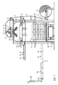
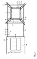
- FIGS. 1 and 2 embodiment shown comprises a device frame 1, between the vertical uprights a transport path 2 for supplying and discharging stacks of goods 3, which are each formed from a plurality of stacked piece goods, is arranged.
- a roller 4 is mounted, which is formed by wound tubular film 5.
- the side edges of the tubular film 5 are folded in the wound state.
- the tubular film 5 is fed via deflecting rollers 6 and take-off rollers 7 to a threading device which has vertically movable guide elements 8.
- the device further comprises a separating device 9 and a welding device 10.
- roof-shaped double conveyor belts 11 are arranged in a known manner on both sides of the device frame 1, the upper receiving ends are located directly below the guide elements 8 in its vertically lowered position.
- the double conveyor belts instead of the double conveyor belts, another means for opening the film may be provided.
- a vertically movable frame 12 On the four uprights of the device frame 1, a vertically movable frame 12, which is guided vertically on the uprights, is provided. This carries four Sp Dahlfinger 13 and the Sp Dahlfingern 13 associated Reffrollen 14 which are movable relative to the Sp Dahlfingern 13 and attached to the frame 12.
- the frame 12 carries guide rails 15 which project beyond the device frame 1 on one side.
- a loading slider 16 is guided horizontally movable, which is displaceable from a position laterally adjacent to the device frame 1, which is referred to as a loading position, into a position in which the loading slider 16 is located within the device frame 1 and in the To be referred to below as a stacking position.
- the loading slider 16 is slidably guided in the guide rails 15 and further provided with drive means for reciprocating the charge slider 16 between the two aforementioned positions.
- the embodiment shown in the figures has a height-adjustable lifting table 17, which completes the transport path 2 in its lowered position.
- a pallet with a stack of goods provided thereon from stacked stack layers with, for example, five bags 19 is reproduced on this lifting table 17.
- the lifting table 17 has rollers 20, of which at least one roller is driven. These rollers form a roller conveyor 20, which completes the transport path 2 in the lowered position of the lifting table 17.
- an inlet track 21 is furthermore shown, which is provided above an inlet table 22 and to which a pusher 23 is assigned.
- the pusher 23 is driven by a motor and can be moved from a position near the front edge of the feed table 22 to a retracted position remote therefrom.
- Perpendicular to the extension direction of the inlet table 22 according to FIG. 1 extends a transport path, which is associated with a device not known here and known for the predetermined arrangement of bags 19 on the transport table. With this device can occasionally the device supplied bags 19 are moved transversely to the transport direction and rotated. By this means can thus be created in the plane of the transport route, a composite of bags in a predetermined arrangement. This predetermined arrangement of sacks forms the stack layer 18 within the stack 3.
- the front edge of the inlet table 22 is located approximately at the height of the loading slider in the loading position.
- the loading slider at the loading station can be arranged in such a way that a storage surface 24 formed by the loading slider 16 is level with the plane of the inlet path 21 (cf. Fig. 1 dashed outline).
- a previously formed on the inlet track 21 stack layer ie a predetermined arrangement of bags 19 in a plane by pressing the pusher 23 is deposited on the shelf 24.
- the thus loaded loading slider 16 is then raised by moving the frame 12 relative to the device frame 1, to such an extent that the frame 12 is above the in FIG. 1 shown, not yet finished stack 3 is located.
- the frame is now lowered until the loading slide 16 is provided immediately above the uppermost layer of the stack.
- the loading slider 16 is moved from the stacking position to the loading position, wherein in this movement on the frame 12 movably provided retaining elements hold the stacking surface 24 deposited stacking layer in position. Accordingly, the charge slider 16 extends below the stack layer 18 away. This lies down on the stack 3.
- the ripper fingers 13 are moved apart together with the reefing rolls 14 in order to stretch the film elastically to a circumference which is greater than the circumference of the stack of articles 3.
- the loading slide 16 remains in the loading position, that is located laterally next to the device frame. 1
- the lifting table 17 Before or during the coating movement of the lifting table 17 is raised.
- the lifting table it is possible to provide the device frame 1 relatively close to the transport path 2 and the frame 12 to arrange relatively tightly around the outer periphery of the stack 3, whereby a space-saving device is created without the risk that in the lower portion of the coating movement the hose hood on the stack of articles 3, the parts of the device movable in the vertical direction and mounted on the frame 12 with stationary parts of the plant, especially the parts of the transport path 2 provided in the region of the device collide.
Abstract
Description
Die vorliegende Erfindung betrifft eine Vorrichtung zum Herstellen einer Verpackungseinheit, die mehrere zu einem Gutstapel gestapelte Verpackungsgegenstände umfasst. Die Vorrichtung hat eine Einrichtung zum Umhüllen des Gutstapels umfassend eine Reffeinrichtung zum Aufreffen und Überziehen einer Schlauchhaube über den Gutstapel.The present invention relates to an apparatus for manufacturing a packaging unit comprising a plurality of packaging items stacked in a stack of goods. The device has a device for wrapping the stack of goods comprising a Reffeinrichtung for receiving and coating a hose cover over the stack.
Eine vorbekannte Vorrichtung zum Herstellen einer solchen Verpackungseinheit ist beispielsweise aus der auf die Anmelderin zurückgehenden
Bei der gattungsgemäßen Vorrichtung umfasst die Einrichtung zum Umhüllen des Gutstapels üblicherweise ein Gestell, unter dem der Gutstapel auf einer Fahrstrecke angeordnet wird und welches oberhalb des Gutstapels Zuführ-, Trenn- und Schweißeinrichtungen aufweist, um eine üblicherweise seitlich an dem Gestell als Rolle gehaltene Endlosbahn des zum Umhüllen des Gutstapels verwendeten Folienmaterials auf Länge zu schneiden und oberseitig mit einer Schweißnaht zu versehen. Die so gebildete Schlauchhaube wird ebenfalls im oberen Bereich des Gestells über Transportbänder so aufgespannt, dass Refffinger der Reffeinrichtung von unten in die unterseitig offene Haube eingreifen und das offene Ende der Haube fassen können.In the generic device, the device for wrapping the stack usually includes a frame under which the stack is placed on a route and which above the stack of feed, separation and welding equipment to a usually held laterally on the frame as a roller endless web of for wrapping the stack of material used to cut material to length and to provide the upper side with a weld. The tubular hood thus formed is also stretched over conveyor belts in the upper region of the frame in such a way that the reefing fingers of the reefing device can engage from below into the underside of the open hood and grasp the open end of the hood.
Neben Refffingern weist die Reffeinrichtung üblicherweise Reffrollen auf, die mit einer durch die Refffinger gebildeten Gegenfläche zusammenwirken und zwischen dieser und sich das Folienmaterial klemmen können, um zum Einen vor dem Überziehen des Gutstapels mit der Schlauchhaube diese faltenbalgartig auf die Refffinger aufzureffen. Beim Überziehen der Schlauchhaube über den Gutstapel können die Reffrollen von dem Folienmaterial beabstandet sein, so dass sich das Folienmaterial beim Überziehen über den Gutstapel selbsttätig von den Refffingern abzieht. Die Reffrollen können aber auch eingesetzt werden, um beim Überziehen des Gutstapels einen erheblichen Widerstand aufzubauen, so dass die zwischen Refffingern und Reffrollen geklemmte Schlauchfolie mit erheblicher Längsdehnung an den Gutstapel angelegt wird. Denkbar ist beispielsweise das Bremsen oder gegenläufige Antreiben der Rollen beim Überziehen über den Gutstapel. Auch können die Reffrollen in einer Weise angetrieben werden, dass bewusst Schlauchmaterial an einer vorbestimmten Stelle oder einem vorbestimmten Bereich im Rahmen des Überziehens dem Gutstapel zugeführt wird.In addition to Refffingern the Reffeinrichtung usually Reffrollen, which cooperate with a formed by the Refffinger counter surface and can clamp between this and the film material, on the one hand before the covering of the stack with the hose hood aufzuscheffen this bellows on the Refffinger. When coating the hose cap over the stack, the refroll can be spaced from the film material, so that the film material automatically deducted when coating over the stack of the refusers. However, the reef rolls can also be used to build up a considerable resistance when covering the stack, so that the clamped between Refffern and Reffrollen tubular film is applied to the stack with considerable longitudinal expansion. It is conceivable, for example, the braking or counter-rotating driving the rollers when coating over the stack. Also, the reefing rollers may be driven in a manner deliberately supplying tubing at a predetermined location or a predetermined area in the course of coating to the stack.
Vor dem Überziehen des Gutstapels wird dieser durch Stapeln verschiedener Packungsgegenstände gebildet. Zwar können die Gutstapel unterschiedliche Verpackungsgegenstände umfassen. Häufig werden aber gattungsgemäße Verpackungseinheiten, insbesondere in der Zement- oder Kunststoffindustrie erstellt und aus jeweils identischen Gegenständen gebildet. Bei diesen handelt es sich dann häufig um Säcke aus Schüttgut.Before coating the stack of goods this is formed by stacking various items of packaging. Although the stacks can include different packaging items. Frequently, however, generic packaging units, in particular in the cement or plastics industry, are created and formed from identical objects. These are then often bags of bulk material.
Es ist bekannt, entsprechend der Verpackungseinheiten, durch automatisiertes Stapeln der einzelnen Lagen umfassend mehrere Verpackungsgegenstände auszubilden.It is known, according to the packaging units, to form a plurality of packaging articles by automated stacking of the individual layers.
Der vorliegenden Erfindung liegt das Problem zugrunde, eine Vorrichtung und ein Verfahren anzugeben, mit denen Verpackungseinheiten wirtschaftlich hergestellt werden können.The present invention is based on the problem to provide a device and a method by which packaging units can be produced economically.
Zur Lösung des vorrichtungsmäßigen Problems wird mit der vorliegenden Erfindung die eingangs genannte Vorrichtung durch einen Rahmen weitergebildet, der nicht nur die Reffeinrichtung hält, sondern der darüber hinaus wenigstens einen beweglichen Ladeschieber hat, der innerhalb des Rahmens eine Ablagefläche für Verpackungsgegenstände schaffen kann und der in eine Position seitlich neben den Gutstapel bringbar ist. So können von dem Rahmen gehaltene Verpackungsgegenstände als Stapellage auf den noch nicht fertiggestellten Gutstapel abgelegt werden.To solve the device problem with the present invention, the device mentioned above is further developed by a frame that holds not only the Reffeinrichtung, but also has at least one movable loading slider that can create a shelf for packaging items within the frame and in a Position can be brought laterally next to the stack. Thus, packaging objects held by the frame can be deposited as a stacking layer on the still unfinished stack of goods.
Die vorliegende Erfindung will daher eine Einheit aus Palettierautomat zum Herstellen des Gutstapels und Umhüllungsautomat zum Umhüllen des Gutstapels mit Folienmaterial angeben. Während indes im Stand der Technik zunächst der Gutstapel gestapelt und dann in einer separaten Umhüllungsstation mit Folienmaterial umhüllt wird, ist es mit der vorliegenden Erfindung möglich, beide Verfahrensschritte beim Herstellen der Verpackungseinheit an einer einzigen Position durchzuführen.The present invention therefore intends to specify a unit of palletizing machine for producing the stack of goods and wrapping machine for wrapping the stack of goods with film material. While in the prior art, the stack of goods is first stacked and then wrapped in a separate wrapping station with film material, it is possible with the present invention to carry out both method steps in producing the packaging unit at a single position.
Der Rahmen der erfindungsgemäßen Vorrichtung ist in vertikaler Richtung beweglich, um beispielsweise an einer ersten Position zu stapelnde Verpackungsgegenstände in einer Lage aufzunehmen. Diese Stapellage an Verpackungsgegenständen kommt auf der Ablagefläche zum Liegen. Eine Einrichtung zum Ausrichten der einzelnen Verpackungsgegenstände innerhalb der Stapellage kann vorgeschaltet sein.The frame of the device according to the invention is movable in the vertical direction, for example, to receive packaging articles to be stacked at a first position in one layer. This stack layer of packaging objects comes to rest on the shelf. A means for aligning the individual packaging items within the stack layer may be upstream.
Die so auf der Ablagefläche gebildete Stapellage wird durch vertikale Bewegung des Rahmens im Falle der ersten Lage des Gutstapels beispielsweise unmittelbar oberhalb einer Palette angeordnet. Der wenigstens eine Ladeschieber fährt danach aus dem Rahmen heraus, so dass die Verpackungsgegenstände der Stapellage nach unten aus dem Rahmen abfallen, bei dem besagten Ausführungsbeispiel zunächst auf die Palette.The stacking layer thus formed on the shelf surface is arranged by vertical movement of the frame in the case of the first layer of the stack, for example, immediately above a pallet. The at least one loading slide then moves out of the frame, so that the packaging objects of the stacking layer fall down from the frame, in the said embodiment, first on the pallet.
Der Rahmen fährt dann in eine andere Position, um weitere Verpackungsgegenstände zu einer zweiten Stapellage aufzunehmen. Diese Stapellage wird auf die zunächst gebildete erste Stapellage abgelegt, nachdem der Rahmen mit seinem Ladeschieber abgesenkt unmittelbar oberhalb der ersten Stapellage befindlich ist. Auf diese Weise werden sämtliche Lagen des Gutstapels übereinander gestapelt.The frame then moves to a different position to receive additional packaging items to a second stack location. This stack layer is deposited on the initially formed first stack layer, after the frame with its loading slider lowered is located directly above the first stack layer. In this way, all layers of the stack are stacked on top of each other.
Der auf diese Weise hergestellte Gutstapel wird nunmehr mit einer Folie umhüllt. Dazu nimmt die an dem Rahmen befestigte Reffeinrichtung die Schlauchhaube auf, die vorzugsweise durch eine an einem den Rahmen haltenden Gestell oberhalb des Rahmens montiert ist, um in an sich bekannter Weise schlauchförmiges Folienmaterial zuzuführen, abzulängen, oberseitig zu verschweißen und zu spreizen, so dass Refffinger der Reffeinrichtung unterseitig in die so gebildete Schlauchhaube eingreifen können. Diese wird dann in an sich bekannter Weise durch horizontales Auseinanderfahren der Refffinger umfänglich gedehnt. Der Rahmen bewegt sich danach in vertikaler Richtung entlang des Gutstapels, so dass dieser mit der zunächst von dem Rahmen gehaltenen Schlauchhaube umhüllt wird.The stack of goods produced in this way is now wrapped with a film. For this purpose, the attached to the frame Reffeinrichtung the hose hood, which is preferably mounted by a frame holding frame above the frame to supply in a conventional manner tubular film material, cut, welded on top and spread, so that Refffinger the reefing device can engage in the underside of the thus formed hose hood. This is then extensively stretched in a conventional manner by horizontally moving apart the refffinger. The frame then moves in the vertical direction along the stack of goods, so that it is wrapped with the first held by the frame hose hood.
Als Rahmen im Sinne der Erfindung muss nicht notwendigerweise ein Gebilde angesehen werden, welches umfänglich geschlossen ist. Als Rahmen in diesem Sinne ist insbesondere ein Maschinengestell anzusehen, welches den beweglichen Ladeschieber in der Horizontalen beweglich hält und hinreichend versteift ist, um eine auf der Ablagefläche abgelegte Stapellage zu halten. Die zum Stapeln erforderliche vertikale Beweglichkeit des Rahmens wird genutzt, um auch den fertig gestapelten Gutstapel durch Verfahren des Rahmens entlang des Gutstapels zu umhüllen. Der nach dem Stapeln des Gutstapels ohnehin im oberen Bereich befindliche Rahmen wird dazu mit der Schlauchhaube bestückt, die danach auf der Reffeinrichtung gehalten ist. Ein neuerliches Bewegen des Rahmens entlang des Gutstapels führt schließlich zum Umhüllen desselben mit der Schlauchhaube.As a framework within the meaning of the invention does not necessarily have to be considered a structure which is circumferentially closed. As a frame in this sense, in particular, a machine frame is to be considered, which holds the movable loading slider in the horizontal and is sufficiently stiffened to hold a deposited on the shelf stack layer. The vertical mobility of the frame required for stacking is used to envelop the stacked stack of goods by moving the frame along the stack of goods. The frame, which is in any case located in the upper area after stacking the stack, is equipped with the hose hood, which is then held on the reefing device. A renewed movement of the frame along the stack eventually leads to the wrapping of the same with the hose hood.
Die erfindungsgemäße Vorrichtung erlaubt das Erstellen und Umhüllen des Gutstapels in einer einheitlichen Vorrichtung, wodurch der Investitionsaufwand zum automatisierten Herstellen von Verpackungseinheiten deutlich reduziert ist. Speziell wird die ohnehin vorhandene Führung des vertikal beweglichen Rahmens genutzt, um sowohl den Gutstapel auszubilden, als auch diesen zu umhüllen.The inventive device allows the creation and wrapping of the stack in a single device, whereby the investment cost for the automated production of packaging units is significantly reduced. Specifically, the already existing leadership of the vertically movable frame is used to both form the stack, as well as to wrap this.
Gemäß einer bevorzugten Weiterbildung der vorliegenden Erfindung ist der Ladeschieber quer beweglich an dem besagten Gestell montiert, so dass der Ladeschieber von einer Beladungsstation des Rahmens, an der die Verpackungsgegenstände auf die Ablagefläche aufschiebbar sind, in eine Stapelposition; an der die Verpackungsgegenstände über einer Transportbahn ablegbar sind, hin- und her beweglich ist. Mit der Formulierung von Anspruch 2 soll zunächst zum Ausdruck gebracht werden, dass die Beladungsstation sowie die Transportbahn selbst nicht notwendigerweise Teil der Weiterbildung nach Anspruch 2 sind. Sie können indes Teil der Vorrichtung sein. In der Beladungsstation ist die Ablagefläche vorzugsweise derart vorgesehen, dass diese im Wesentlichen höhengleich zu einer Einlaufbahn vorgesehen ist, auf der eine zuvor gebildete Stapellage für den Gutstapel bereitgehalten wird, wobei ein Überschieber der Einlaufbahn zugeordnet ist, um die so bereitgehaltene Stapellage auf die Ablagefläche des Beladungsschiebers durch horizontales Verschieben zu überführen.According to a preferred embodiment of the present invention, the loading slider is mounted transversely movable on the said frame, so that the loading slider from a loading station of the frame, on which the packaging objects are pushed onto the storage surface, in a stacking position; at which the packaging objects can be deposited over a transport path, is reciprocally movable. With the wording of
Nach Bilden der Stapellage und Ablegen derselben auf dem Ladeschieber wird der Rahmen danach in vertikaler Richtung verschoben und danach die Stapellage durch horizontales Verfahren des Ladeschiebers über die Transportbahn verbracht, auf der beispielsweise eine Palette zum Ablegen der Stapellage wartet. Bei einer platzsparenden Anordnung kann beispielsweise lediglich ein Ladeschieber vorgesehen sein, der an dem Rahmen in der Horizontalen beweglich ist. Die durch den Ladeschieber gebildete Ablagefläche kann aber auch fraktioniert gebildet sein durch mehrere Ladeschieberelemente, die relativ zueinander beweglich sind. So ist es beispielsweise denkbar, die Ladeschiebersegmente zum Ablegen der Stapellage auf dem Gutstapel in unterschiedliche Richtungen zu verfahren, um mittig eine Öffnung freizugeben, durch die die Stapellage auf dem Gutstapel abgelegt werden kann. Diese Beweglichkeit des Ladeschiebers erfolgt über Führungen, die identisch, jedenfalls aber üblicherweise parallel zu den Führungen des Rahmens vorgesehen sind, um diesen zwischen der Beladungsstation und der Stapelposition hin- und her zu bewegen. Vorzugsweise weist der Rahmen eine bewegliche Gegenfläche auf, die zum Einbringen der Stapellage über die Stapel in die Stapelposition wegbewegt werden kann, so dass die Stapellage ungehindert in die Stapelposition überführt werden kann, wohingegen die Gegenfläche in etwa bis auf die Ebene des Ladeschiebers abgesenkt ist, so dass die zunächst geringfügig mit der Ablagefläche bewegten Verpackungsgegenstände gegen die Gegenfläche stoßen und sich der Ladeschieber unterhalb der Stapellage wegziehen kann, so dass die Verpackungsgegenstände an der Stapelposition aus dem Rahmen fallen und stapelnd abgelegt werden können.After forming the stack layer and depositing the same on the loading slide the frame is then moved in the vertical direction and then spent the stack layer by horizontal movement of the loading slider on the transport path, waiting for example, a pallet for storing the stack layer. In a space-saving arrangement, for example, only a loading slider can be provided, which is movable on the frame in the horizontal. The storage surface formed by the loading slide can also be fractionally formed by a plurality of loading slide elements which are movable relative to each other. Thus, it is conceivable, for example, to move the loading slide segments for depositing the stack layer on the goods stack in different directions in order to release an opening in the middle, by means of which the stack layer can be deposited on the goods stack. This mobility of the loading slider via guides that are identical, but in any case usually provided parallel to the guides of the frame to move back and forth between the loading station and the stacking position. Preferably, the frame has a movable mating surface which can be moved away from the stack to the stacking position for insertion of the stack layer, so that the stack layer can be freely transferred to the stacking position, whereas the mating surface is lowered approximately to the level of the loading slider, so that the initially slightly moved with the tray surface packaging objects abut against the counter surface and the loading slider can pull away below the stack layer, so that the packaging objects fall at the stacking position of the frame and can be stored stacking.
Gemäß einer bevorzugten Weiterbildung der vorliegenden Erfindung ist an dem Gestell eine zum Spreizen einer Folienbahn geeignete Spreizeinrichtung oberhalb des Rahmens ortsfest befestigt. Diese Spreizeinrichtung bildet den Abschluss einer Zuführstrecke von auf einer Rolle endlos bereitgestelltem schlauchförmigen Folienmaterial, die der Spreizeinrichtung vorgelagert Zuführmittel in Form von Umlenk- und Antriebsrollen, eine Schneideinrichtung zum Abschneiden eines vorbestimmten Längenstücks von dem Folienvorrat, und eine Schweißeinrichtung zum Verschließen des zugeführten Folienmaterials zur Ausbildung einer Schlauchhaube hat.According to a preferred embodiment of the present invention, a spreader suitable for spreading a film web is fastened fixedly above the frame on the frame. This spreader constitutes the completion of a feed path of tubular film material endlessly provided on a roll, the feed means in the form of diverting and driving rollers upstream, a cutter for cutting a predetermined length of the film supply, and welding means for closing the fed sheet material for formation a hose hood has.
Nach Beendigung des Stapelvorgangs nimmt der Rahmen mit seiner Reffeinrichtung die an der Spreizeinrichtung bereit gehaltene Schlauchhaube auf. Es ist danach allerhöchstens ein geringer Verfahrweg erforderlich, um von der Lage des Rahmens nach Abschluss des Stapelns diesen Rahmen in eine Position zu bringen, in welcher dieser die Schlauchhaube oberhalb des Gutstapels in der Stapelposition erfasst. Nach Aufreffen der Schlauchhaube wird diese in an sich bekannter Weise (vgl. bspw.
Eine Schlauchhaube im Sinne der vorliegenden Erfindung muss nicht notwendigerweise ein oberseitig geschlossenes Gebilde sein. Bisweilen kommt es lediglich darauf an, den Gutstapel umfänglich zu fassen.A hose hood in the sense of the present invention does not necessarily have to be a top-side closed structure. Sometimes it is only important to comprehend the stack of goods.
Gemäß einer weiteren bevorzugten Ausgestaltung der vorliegenden Erfindung umfasst die Vorrichtung einen Hubtisch, der bis auf die Höhe der Transportbahn absenkbar ist und in dieser abgesenkten Position die Transportbahn komplettiert und sich unterhalb des Rahmens in seiner Stapelposition befindet. Mit dem Hubtisch kann der fertig gestellte Gutstapel beim Überziehen der Schlauchhaube angehoben werden, so dass die von dem Rahmen übergezogene Schlauchhaube bis zu der untersteten Stapellage, gegebenenfalls auch bis unter die Palette eines Gutstapels übergezogen werden kann. Dabei ist zu beachten, dass sich die Refffinger regelmäßig im oberen Bereich des Rahmens befinden, so dass diese beim automatisierten Stapeln der Verpackungslagen nicht mit der Transportbahn oder dergleichen kollidieren können. Der Hubtisch sollte eine Höhenbeweglichkeit von wenigstens dem Höhenabstand zwischen dem Ladeschieber und den Refffingern des Rahmens haben.According to a further preferred embodiment of the present invention, the device comprises a lifting table, which can be lowered to the height of the transport path and in this lowered position completes the transport path and is located below the frame in its stacking position. With the lifting table, the finished stack can be lifted when coating the hose hood, so that the coated from the frame hose hood can be pulled up to the bottom of the stacked stack, possibly even to the pallet of a stack of goods. It should be noted that the refining fingers are regularly in the upper region of the frame, so that they are not in the automated stacking of the packaging layers with the transport path or the like can collide. The lift table should have a height mobility of at least the height distance between the loading slider and the refiner of the frame.
Der Transporttisch komplettiert vorzugsweise die Rollenbahn und hat dementsprechend Rollen, auf denen die Verpackungseinheit auf dem Transportweg rollen kann. Ausgewählte, üblicherweise ortsfest vorgesehene Rollen, die Teil des Hubtisches sind, sind vorzugsweise als Antriebsrollen motorisch angetrieben.The transport table preferably completes the roller conveyor and accordingly has rollers on which the packaging unit can roll on the transport path. Selected, usually fixed rollers provided, which are part of the lifting table, are preferably driven by a motor as drive rollers.
Zur Lösung des verfahrensmäßigen Aspektes wird mit der vorliegenden Erfindung ein Verfahren zum Herstellen einer Verpackungseinheit angegeben, bei dem an einer Stapelposition der Gutstapel durch übereinanderlegen von Lagen an Verpackungsgegenständen gebildet wird und der so gebildete Gutstapel an der Stapelposition mit einer Schlauchhaube überzogen wird. Beide Verfahrensschritte, d.h. das Stapeln und das Überziehen erfolgen bei dem erfindungsgemäßen Verfahren automatisiert. Speziell verbleibt der gebildete Gutstapel nach dem Stapeln ortsfest bis zum Überziehen mit der Schlauchhaube. Allerhöchstens kann der Gutstapel beim Stapeln und/oder während des Überziehens in der Vertikalen bewegt werden. Eine horizontale Verlagerung des Gutstapels ist nicht erforderlich.To solve the procedural aspect of the present invention, a method for producing a packaging unit is specified, is formed at a stacking position of the stack by superimposing layers of packaging objects and the stack thus formed is coated at the stacking position with a hose cap. Both process steps, i. Stacking and coating are automated in the method according to the invention. Specifically, after stacking, the stack formed remains stationary until it is coated with the hose hood. At the most, the stack can be moved in the vertical direction during stacking and / or during coating. A horizontal displacement of the stack is not required.
Die bevorzugten Weiterbildungen des erfindungsgemäßen Verfahrens sind bereits vorstehend angesprochen worden.The preferred developments of the method according to the invention have already been mentioned above.
Eine besonders rasche und daher wirtschaftliche Verfahrensführung ergibt sich dadurch, dass der die Lagen bildende Rahmen nach dem Stapeln der Verpackungseinheit in einer oberhalb des Gutstapels gegebenen Überzieh-Ausgangsstellung eine Schlauchhaube aufnimmt. Diese Überzieh-Ausgangsstellung kann identisch mit denjenigen Stellungen des Rahmens sein, in der sich dieser beim Ablegen der letzten Lage auf dem Gutstapel befindet. Die Überzieh-Ausgangsposition kann gegenüber dieser höchsten Position des Rahmens beim Stapeln des Gutstapels auch leicht erhöht sein. Aus der Überzieh-Ausgangslage erfolgt lediglich ein Absenken des Rahmens über den Gutstapel, um die Schlauchhaube auf den Gutstapel überzuziehen. Mit anderen Worten wird der Rahmen zwischen dem Ablegen der letzten Stapellage und dem Überziehen der Schlauchhaube über den Gutstapel lediglich in vertikaler Richtung bewegt.A particularly rapid and therefore economical process management results from the fact that the frame forming the layers receives a tubular cover after the packaging unit has been stacked in a covering initial position above the product stack. This cover-home position can be identical to those positions of the frame in which this is when placing the last layer on the stack. The stall home position may also be slightly elevated from this highest position of the frame when stacking the stack. From the stall-starting position, only a lowering of the frame over the stack is done to cover the hose cover on the stack. In other words, the frame between the deposition of the last stack layer and the coating of the hose cover over the stack is only moved in the vertical direction.
Bevorzugte Weiterbildungen des Verfahrens sind in den Ansprüchen 10 und 11 angegeben.Preferred developments of the method are given in
Die Erfindung wird nachfolgend unter Bezugnahme auf ein Ausführungsbeispiel in Verbindung mit der Zeichnung näher erläutert. In dieser zeigen:
- Figur 1
- eine Seitenansicht auf ein Ausführungsbeispiel der Vorrichtung und
Figur 2- eine Draufsicht auf das in
Figur 1 gezeigte Ausführungsbeispiel.
- FIG. 1
- a side view of an embodiment of the device and
- FIG. 2
- a top view of the in
FIG. 1 shown embodiment.
Das in den
Unterhalb der Leitelemente 8 sind in bekannter Weise auf beiden Seiten des Vorrichtungsgestells 1 dachförmig verlaufende Doppelförderbänder 11 angeordnet, deren obere Aufnahmeenden unmittelbar unterhalb der Leitelemente 8 in deren vertikal abgesenkter Stellung befindlich sind. Anstelle der Doppelförderbänder kann auch eine andere Einrichtung zum Öffnen der Folie vorgesehen werden.Below the
An den vier Ständern des Vorrichtungsgestells 1 ist ein vertikal beweglicher und an den Ständern vertikal geführter Rahmen 12 vorgesehen. Dieser trägt vier Spreizfinger 13 und den Spreizfingern 13 zugeordnete Reffrollen 14, die relativ zu den Spreizfingern 13 verfahrbar und an dem Rahmen 12 befestigt sind.On the four uprights of the device frame 1, a vertically
Unterhalb der Spreizfinger 13 und der Reffrollen 14 trägt der Rahmen 12 Führungsschienen 15, die das Vorrichtungsgestell 1 einseitig überragen. Über diese Führungsschienen 15 ist ein Ladeschieber 16 horizontal beweglich geführt, der von einer Position seitlich neben dem Vorrichtungsgestell 1, die im Folgenden als Beladungsposition bezeichnet wird, in eine Position verschiebbar ist, in der sich der Ladeschieber 16 innerhalb des Vorrichtungsgestells 1 befindet und die im Folgenden als Stapelposition bezeichnet werden soll. Der Ladeschieber 16 ist in den Führungsschienen 15 verschieblich geführt und darüber hinaus mit Antriebsmitteln versehen, um den Ladungsschieber 16 zwischen den beiden vorerwähnten Positionen hin- und herzuverfahren.Below the spreading
Im unteren Bereich weist das in den Figuren gezeigte Ausführungsbeispiel einen höhenbeweglichen Hubtisch 17 auf, der in seiner abgesenkten Position die Transportbahn 2 komplettiert. In der Zeichnung ist auf diesen Hubtisch 17 eine Palette mit einem darauf vorgesehenen Gutstapel gebildet aus übereinander geschichteten Stapellagen mit beispielsweise jeweils fünf Säcken 19 wiedergegeben. Der Hubtisch 17 weist Rollen 20 auf, von denen wenigstens eine Rolle angetrieben ist. Diese Rollen bilden eine Rollenbahn 20, die die Transportbahn 2 in der abgesenkten Position des Hubtisches 17 komplettiert.In the lower region, the embodiment shown in the figures has a height-adjustable lifting table 17, which completes the
Im untern Bereich der Vorrichtung ist weiterhin eine Einlaufbahn 21 gezeigt, die oberhalb eines Einlauftisches 22 vorgesehen und welcher ein Überschieber 23 zugeordnet ist. Der Überschieber 23 ist motorisch angetrieben und kann von einer nahe der vorderen Kante des Einlauftisches 22 befindlichen Position in eine davon entfernte zurückgezogene Position verfahren werden. Rechtwinklig zu der Erstreckungsrichtung des Einlauftisches 22 gemäß
Die vordere Kante des Einlauftisches 22 befindet sich in etwa auf Höhe des Ladeschiebers in der Beladungsposition. Durch Absenken des Rahmens 2 von der in
Durch alternierendes Anfahren der Beladungsstation und Ablegen der dort aufgenommenen Stapellage 18 auf den Stückgutstapel 3 wird dieser fertiggestellt. Nach dem Stapeln der letzten Lage des Stückgutstapels 3 verfährt der Rahmen 12 in Richtung auf die Spreiz- bzw. Fördereinrichtung 11 für die Schlauchfolie 5 in eine Überzieh-Ausgangsstellung. Dort wird bei zusammengefahrenen Spreizfingern 13 Folienmaterial auf die Spreizfinger gefördert. Die Reffrollen 14 klemmen die Folie zwischen sich und den Spreizfingern 13 in an sich bekannter Weise (vgl. beispielsweise
Durch Absenken des Rahmens 12 wird nunmehr die zuvor gebildete Schlauchhaube über den Gutstapel gezogen. Am Ende dieser Überziehbewegung ist die Schlauchhaube vollständig über den Gutstapel 3 einschließlich Palette gezogen.By lowering the
Vor oder während der Überziehbewegung wird der Hubtisch 17 angehoben. Durch den Hubtisch ist es möglich, das Vorrichtungsgestell 1 relativ nahe an der Transportbahn 2 vorzusehen und den Rahmen 12 relativ eng um den Außenumfang des Gutstapels 3 anzuordnen, wodurch eine raumsparende Vorrichtung geschaffen ist, ohne dass die Gefahr besteht, dass im unteren Abschnitt der Überziehbewegung der Schlauchhaube über den Stückgutstapel 3 die in vertikaler Richtung beweglichen und an dem Rahmen 12 montierten Teile der Vorrichtung mit ortsfesten Anlagenteilen, speziell den im Bereich der Vorrichtung vorgesehenen Teilen der Transportbahn 2 kollidieren.Before or during the coating movement of the lifting table 17 is raised. By the lifting table, it is possible to provide the device frame 1 relatively close to the
- 11
- Vorrichtungsgestelldevice stand
- 22
- Transportbahntransport path
- 33
- Stückgutstapelstack of packaged goods
- 44
- Rollerole
- 55
- Schlauchfolietubular film
- 66
- Umlenkrollenguide rollers
- 77
- Abzugsrollenoff rollers
- 88th
- Leitelementebaffles
- 99
- Trenneinrichtungseparator
- 1010
- Schweißeinrichtungwelding equipment
- 1111
- Doppelförderband (Spreizeinrichtung)Double conveyor belt (spreading device)
- 1212
- Rahmenframe
- 1313
- Spreizfingerspreading fingers
- 1414
- Reffrollefurling foil
- 1515
- Führungsschienenguide rails
- 1616
- Ladeschieberloading slide
- 1717
- HubtischLift table
- 1818
- Stapellagestack layer
- 1919
- Säckebags
- 2020
- Rollenbahnroller conveyor
- 2121
- Einlaufbahnentry path
- 2222
- Einlauftischinfeed table
- 2323
- Überschieberoverslide
- 2424
- Ablageflächeshelf
Claims (11)
einen die Reffeinrichtung (13, 14) haltenden Rahmen (12), an dem wenigstens ein beweglicher Ladeschieber (16) vorgesehen ist, durch den innerhalb des Rahmens (12) eine Ablagefläche (24) für Verpackungsgegenstände (19) geschaffen werden kann und der in eine Position seitlich neben den Gutstapel (3) bringbar ist.Apparatus for producing a packaging unit comprising a plurality of packaging articles (19) stacked into a stack (3), comprising means (10, 11, 13, 14) for wrapping the stack (3) comprising a reefing device (13, 14) for striking and coating a hose hood over the stack (3), characterized by
a frame (12) holding the reefing means (13, 14) on which there is provided at least one movable loading slide (16) through which a shelf (24) for packaging articles (19) can be created inside the frame (12) and which is in a position can be brought laterally next to the stack of goods (3).
Applications Claiming Priority (1)
| Application Number | Priority Date | Filing Date | Title |
|---|---|---|---|
| DE102009024002A DE102009024002B3 (en) | 2009-06-05 | 2009-06-05 | Device and method for producing a packaging unit |
Publications (3)
| Publication Number | Publication Date |
|---|---|
| EP2258618A2 true EP2258618A2 (en) | 2010-12-08 |
| EP2258618A3 EP2258618A3 (en) | 2011-10-05 |
| EP2258618B1 EP2258618B1 (en) | 2013-08-28 |
Family
ID=42732685
Family Applications (1)
| Application Number | Title | Priority Date | Filing Date |
|---|---|---|---|
| EP10005751.2A Active EP2258618B1 (en) | 2009-06-05 | 2010-06-02 | Method and device for manufacturing a packaging unit |
Country Status (3)
| Country | Link |
|---|---|
| EP (1) | EP2258618B1 (en) |
| DE (1) | DE102009024002B3 (en) |
| ES (1) | ES2435891T3 (en) |
Cited By (5)
| Publication number | Priority date | Publication date | Assignee | Title |
|---|---|---|---|---|
| WO2012072092A1 (en) * | 2010-11-30 | 2012-06-07 | Maschinenfabrik Möllers Gmbh | Apparatus and method for producing a packaging unit |
| EP2921415A1 (en) * | 2014-03-21 | 2015-09-23 | RH Montagetechnik ApS | Apparatus for packing goods or packages and a method of repairing and servicing the apparatus |
| WO2015140310A1 (en) * | 2014-03-21 | 2015-09-24 | Rh Montagetechnik Aps | Apparatus for packing goods or packages and a method of repairing and servicing the apparatus |
| EP2993134A1 (en) * | 2014-09-05 | 2016-03-09 | OFFICINA MECCANICA SESTESE S.p.A. | Hooding apparatus |
| CN106379595A (en) * | 2016-11-01 | 2017-02-08 | 桐乡市恒泰纸管有限公司 | Automatic packing device for paper pipe |
Families Citing this family (2)
| Publication number | Priority date | Publication date | Assignee | Title |
|---|---|---|---|---|
| DE102013001566A1 (en) * | 2013-01-30 | 2014-07-31 | Beumer Gmbh & Co. Kg | Method for stacking and enclosing cargo stack with e.g. sacks, on palette, involves covering film by enclosing stack, where surface is not moved in horizontal direction from beginning of stacking of stack till to ending of covering of film |
| ES2670069T3 (en) | 2016-10-18 | 2019-09-11 | Maschf Moellers Gmbh | Procedure for manufacturing a packaging unit without pallets and packaging unit manufactured according to the procedure |
Citations (1)
| Publication number | Priority date | Publication date | Assignee | Title |
|---|---|---|---|---|
| EP1013549A1 (en) | 1998-12-23 | 2000-06-28 | Maschinenfabrik Möllers GmbH u. Co. | Method and device for enveloping a stack of goods |
Family Cites Families (9)
| Publication number | Priority date | Publication date | Assignee | Title |
|---|---|---|---|---|
| JPS5190688A (en) * | 1975-02-05 | 1976-08-09 | Sekisonino mitsupuhosohoho | |
| DE2917069A1 (en) * | 1979-04-27 | 1980-11-06 | Bosch Gmbh Robert | Enclosing stacked layers of packs in foil tube - has stack lowered stepwise whilst allowing gathered-in tube top to stretch around stack |
| US4593517A (en) * | 1982-01-06 | 1986-06-10 | Jari Mattila | Method and apparatus for packing goods |
| SE470162B (en) * | 1988-03-14 | 1993-11-22 | Fmc Corp | Automatic controlled packaging and goods stacking device |
| DE3834535A1 (en) * | 1988-09-22 | 1990-03-29 | Beumer Maschf Bernhard | Method and apparatus for wrapping stacks of piece goods with plastic foil |
| DE3832557A1 (en) * | 1988-09-24 | 1990-04-05 | Beumer Maschf Bernhard | Process and apparatus for the formation of packaging units wrapped with plastic foil and packaging unit produced therewith |
| DE4032228A1 (en) * | 1990-04-03 | 1991-10-10 | Hydraulik Vertrieb Hinners Gmb | Wrapping stacks of packages in stretch film - by sticking packages on pallet which is raised by power cylinder |
| US5623808A (en) * | 1996-01-19 | 1997-04-29 | Hk Systems, Inc. | Apparatus and method for palletizing and wrapping a load |
| US5893258A (en) * | 1996-12-20 | 1999-04-13 | Lantech Technology Investment Corp. | Building and wrapping a stabilized load |
-
2009
- 2009-06-05 DE DE102009024002A patent/DE102009024002B3/en not_active Expired - Fee Related
-
2010
- 2010-06-02 ES ES10005751T patent/ES2435891T3/en active Active
- 2010-06-02 EP EP10005751.2A patent/EP2258618B1/en active Active
Patent Citations (1)
| Publication number | Priority date | Publication date | Assignee | Title |
|---|---|---|---|---|
| EP1013549A1 (en) | 1998-12-23 | 2000-06-28 | Maschinenfabrik Möllers GmbH u. Co. | Method and device for enveloping a stack of goods |
Cited By (5)
| Publication number | Priority date | Publication date | Assignee | Title |
|---|---|---|---|---|
| WO2012072092A1 (en) * | 2010-11-30 | 2012-06-07 | Maschinenfabrik Möllers Gmbh | Apparatus and method for producing a packaging unit |
| EP2921415A1 (en) * | 2014-03-21 | 2015-09-23 | RH Montagetechnik ApS | Apparatus for packing goods or packages and a method of repairing and servicing the apparatus |
| WO2015140310A1 (en) * | 2014-03-21 | 2015-09-24 | Rh Montagetechnik Aps | Apparatus for packing goods or packages and a method of repairing and servicing the apparatus |
| EP2993134A1 (en) * | 2014-09-05 | 2016-03-09 | OFFICINA MECCANICA SESTESE S.p.A. | Hooding apparatus |
| CN106379595A (en) * | 2016-11-01 | 2017-02-08 | 桐乡市恒泰纸管有限公司 | Automatic packing device for paper pipe |
Also Published As
| Publication number | Publication date |
|---|---|
| EP2258618A3 (en) | 2011-10-05 |
| DE102009024002B3 (en) | 2011-03-17 |
| ES2435891T3 (en) | 2013-12-26 |
| EP2258618B1 (en) | 2013-08-28 |
Similar Documents
| Publication | Publication Date | Title |
|---|---|---|
| EP2258618B1 (en) | Method and device for manufacturing a packaging unit | |
| EP0344815B2 (en) | Method and device for wrapping products, in particular stacks of products, in a stretchable film cover | |
| DE19732298C1 (en) | Machine for covering stacked articles with film packaging | |
| DE3906922C2 (en) | ||
| CH637342A5 (en) | METHOD AND DEVICE FOR THE AUTOMATIC FILLING OF BAGS IN A FILLING STATION. | |
| DE4207808A1 (en) | METHOD AND DEVICE FOR FEEDING INTERLAYERS TO A STACK | |
| DE4035352A1 (en) | DEVICE FOR PRODUCING BOXES AND FOR PACKING PRODUCTS IN THIS | |
| DE3120215A1 (en) | "PLANT FOR MANUFACTURING PALLETLESS, FILM-SHRINKED PIECE STACK, IN PARTICULAR BAG STACK" | |
| DE102008020486A1 (en) | Device and method for palletizing piece goods compilations | |
| EP2719627A1 (en) | Method and device for wrapping a stack of goods with a film | |
| DE2037003A1 (en) | Method and device for loading containers | |
| EP3665086B1 (en) | Packaging device and packaging method | |
| EP2322433B1 (en) | Method and device for manufacturing a packaging unit | |
| EP2714523B1 (en) | Method and device for producing a palletless packaging unit | |
| DE2636320C2 (en) | Device for the automatic palletizing of objects, in particular bottles | |
| EP3281878B1 (en) | Device for wrapping a stack of goods with a hose hood and method of changing the hose film store in such a device | |
| EP1515894B1 (en) | System for packaging a flexible web that is layered in zigzag loops, in particular a textile web | |
| DE3208544A1 (en) | METHOD AND DEVICE FOR APPLYING SHRINK FILMS ON PALLETED GOETER STACKS | |
| WO2012072092A1 (en) | Apparatus and method for producing a packaging unit | |
| DE3103130A1 (en) | PACKING MACHINE | |
| DE2743568C2 (en) | Method and device for the production of palletless packages | |
| EP1575831B1 (en) | System and method for packaging containers, particularly bottle containers | |
| DE102017203686A1 (en) | DEVICE AND METHOD FOR MAKING A PALLETIZABLE LAYER FROM A MULTIPLE GROUPED MATERIAL COMPOSITION | |
| DE1814742A1 (en) | Machine for continuous marking of packaged goods | |
| DE10303813A1 (en) | Process for applying a film cover onto a packing unit comprises guiding a film tube in a folded state above the packing unit, gripping the film tube using grippers, and moving apart the grippers to pull the foil tube over the packing unit |
Legal Events
| Date | Code | Title | Description |
|---|---|---|---|
| PUAI | Public reference made under article 153(3) epc to a published international application that has entered the european phase |
Free format text: ORIGINAL CODE: 0009012 |
|
| AK | Designated contracting states |
Kind code of ref document: A2 Designated state(s): AL AT BE BG CH CY CZ DE DK EE ES FI FR GB GR HR HU IE IS IT LI LT LU LV MC MK MT NL NO PL PT RO SE SI SK SM TR |
|
| AX | Request for extension of the european patent |
Extension state: BA ME RS |
|
| PUAL | Search report despatched |
Free format text: ORIGINAL CODE: 0009013 |
|
| AK | Designated contracting states |
Kind code of ref document: A3 Designated state(s): AL AT BE BG CH CY CZ DE DK EE ES FI FR GB GR HR HU IE IS IT LI LT LU LV MC MK MT NL NO PL PT RO SE SI SK SM TR |
|
| AX | Request for extension of the european patent |
Extension state: BA ME RS |
|
| RIC1 | Information provided on ipc code assigned before grant |
Ipc: B65B 35/40 20060101ALI20110901BHEP Ipc: B65B 9/13 20060101AFI20110901BHEP Ipc: B65G 57/06 20060101ALI20110901BHEP Ipc: B65G 57/10 20060101ALI20110901BHEP Ipc: B65B 35/50 20060101ALI20110901BHEP |
|
| 17P | Request for examination filed |
Effective date: 20111125 |
|
| 17Q | First examination report despatched |
Effective date: 20121217 |
|
| GRAP | Despatch of communication of intention to grant a patent |
Free format text: ORIGINAL CODE: EPIDOSNIGR1 |
|
| GRAS | Grant fee paid |
Free format text: ORIGINAL CODE: EPIDOSNIGR3 |
|
| GRAA | (expected) grant |
Free format text: ORIGINAL CODE: 0009210 |
|
| AK | Designated contracting states |
Kind code of ref document: B1 Designated state(s): AL AT BE BG CH CY CZ DE DK EE ES FI FR GB GR HR HU IE IS IT LI LT LU LV MC MK MT NL NO PL PT RO SE SI SK SM TR |
|
| REG | Reference to a national code |
Ref country code: GB Ref legal event code: FG4D Free format text: NOT ENGLISH |
|
| REG | Reference to a national code |
Ref country code: CH Ref legal event code: EP |
|
| REG | Reference to a national code |
Ref country code: AT Ref legal event code: REF Ref document number: 629178 Country of ref document: AT Kind code of ref document: T Effective date: 20130915 |
|
| REG | Reference to a national code |
Ref country code: IE Ref legal event code: FG4D Free format text: LANGUAGE OF EP DOCUMENT: GERMAN |
|
| REG | Reference to a national code |
Ref country code: DE Ref legal event code: R096 Ref document number: 502010004476 Country of ref document: DE Effective date: 20131024 |
|
| REG | Reference to a national code |
Ref country code: ES Ref legal event code: FG2A Ref document number: 2435891 Country of ref document: ES Kind code of ref document: T3 Effective date: 20131226 |
|
| REG | Reference to a national code |
Ref country code: LT Ref legal event code: MG4D |
|
| REG | Reference to a national code |
Ref country code: NL Ref legal event code: VDEP Effective date: 20130828 |
|
| PG25 | Lapsed in a contracting state [announced via postgrant information from national office to epo] |
Ref country code: SE Free format text: LAPSE BECAUSE OF FAILURE TO SUBMIT A TRANSLATION OF THE DESCRIPTION OR TO PAY THE FEE WITHIN THE PRESCRIBED TIME-LIMIT Effective date: 20130828 Ref country code: HR Free format text: LAPSE BECAUSE OF FAILURE TO SUBMIT A TRANSLATION OF THE DESCRIPTION OR TO PAY THE FEE WITHIN THE PRESCRIBED TIME-LIMIT Effective date: 20130828 Ref country code: IS Free format text: LAPSE BECAUSE OF FAILURE TO SUBMIT A TRANSLATION OF THE DESCRIPTION OR TO PAY THE FEE WITHIN THE PRESCRIBED TIME-LIMIT Effective date: 20131228 Ref country code: PT Free format text: LAPSE BECAUSE OF FAILURE TO SUBMIT A TRANSLATION OF THE DESCRIPTION OR TO PAY THE FEE WITHIN THE PRESCRIBED TIME-LIMIT Effective date: 20131230 Ref country code: LT Free format text: LAPSE BECAUSE OF FAILURE TO SUBMIT A TRANSLATION OF THE DESCRIPTION OR TO PAY THE FEE WITHIN THE PRESCRIBED TIME-LIMIT Effective date: 20130828 Ref country code: CY Free format text: LAPSE BECAUSE OF FAILURE TO SUBMIT A TRANSLATION OF THE DESCRIPTION OR TO PAY THE FEE WITHIN THE PRESCRIBED TIME-LIMIT Effective date: 20130911 Ref country code: NO Free format text: LAPSE BECAUSE OF FAILURE TO SUBMIT A TRANSLATION OF THE DESCRIPTION OR TO PAY THE FEE WITHIN THE PRESCRIBED TIME-LIMIT Effective date: 20131128 |
|
| REG | Reference to a national code |
Ref country code: NL Ref legal event code: VDEP Effective date: 20130828 |
|
| PG25 | Lapsed in a contracting state [announced via postgrant information from national office to epo] |
Ref country code: FI Free format text: LAPSE BECAUSE OF FAILURE TO SUBMIT A TRANSLATION OF THE DESCRIPTION OR TO PAY THE FEE WITHIN THE PRESCRIBED TIME-LIMIT Effective date: 20130828 Ref country code: SI Free format text: LAPSE BECAUSE OF FAILURE TO SUBMIT A TRANSLATION OF THE DESCRIPTION OR TO PAY THE FEE WITHIN THE PRESCRIBED TIME-LIMIT Effective date: 20130828 Ref country code: LV Free format text: LAPSE BECAUSE OF FAILURE TO SUBMIT A TRANSLATION OF THE DESCRIPTION OR TO PAY THE FEE WITHIN THE PRESCRIBED TIME-LIMIT Effective date: 20130828 Ref country code: GR Free format text: LAPSE BECAUSE OF FAILURE TO SUBMIT A TRANSLATION OF THE DESCRIPTION OR TO PAY THE FEE WITHIN THE PRESCRIBED TIME-LIMIT Effective date: 20131129 Ref country code: PL Free format text: LAPSE BECAUSE OF FAILURE TO SUBMIT A TRANSLATION OF THE DESCRIPTION OR TO PAY THE FEE WITHIN THE PRESCRIBED TIME-LIMIT Effective date: 20130828 |
|
| PG25 | Lapsed in a contracting state [announced via postgrant information from national office to epo] |
Ref country code: CY Free format text: LAPSE BECAUSE OF FAILURE TO SUBMIT A TRANSLATION OF THE DESCRIPTION OR TO PAY THE FEE WITHIN THE PRESCRIBED TIME-LIMIT Effective date: 20130828 |
|
| PG25 | Lapsed in a contracting state [announced via postgrant information from national office to epo] |
Ref country code: DK Free format text: LAPSE BECAUSE OF FAILURE TO SUBMIT A TRANSLATION OF THE DESCRIPTION OR TO PAY THE FEE WITHIN THE PRESCRIBED TIME-LIMIT Effective date: 20130828 Ref country code: EE Free format text: LAPSE BECAUSE OF FAILURE TO SUBMIT A TRANSLATION OF THE DESCRIPTION OR TO PAY THE FEE WITHIN THE PRESCRIBED TIME-LIMIT Effective date: 20130828 Ref country code: SK Free format text: LAPSE BECAUSE OF FAILURE TO SUBMIT A TRANSLATION OF THE DESCRIPTION OR TO PAY THE FEE WITHIN THE PRESCRIBED TIME-LIMIT Effective date: 20130828 Ref country code: RO Free format text: LAPSE BECAUSE OF FAILURE TO SUBMIT A TRANSLATION OF THE DESCRIPTION OR TO PAY THE FEE WITHIN THE PRESCRIBED TIME-LIMIT Effective date: 20130828 Ref country code: NL Free format text: LAPSE BECAUSE OF FAILURE TO SUBMIT A TRANSLATION OF THE DESCRIPTION OR TO PAY THE FEE WITHIN THE PRESCRIBED TIME-LIMIT Effective date: 20130828 Ref country code: CZ Free format text: LAPSE BECAUSE OF FAILURE TO SUBMIT A TRANSLATION OF THE DESCRIPTION OR TO PAY THE FEE WITHIN THE PRESCRIBED TIME-LIMIT Effective date: 20130828 |
|
| REG | Reference to a national code |
Ref country code: DE Ref legal event code: R097 Ref document number: 502010004476 Country of ref document: DE |
|
| PLBE | No opposition filed within time limit |
Free format text: ORIGINAL CODE: 0009261 |
|
| STAA | Information on the status of an ep patent application or granted ep patent |
Free format text: STATUS: NO OPPOSITION FILED WITHIN TIME LIMIT |
|
| 26N | No opposition filed |
Effective date: 20140530 |
|
| REG | Reference to a national code |
Ref country code: DE Ref legal event code: R097 Ref document number: 502010004476 Country of ref document: DE Effective date: 20140530 |
|
| PG25 | Lapsed in a contracting state [announced via postgrant information from national office to epo] |
Ref country code: LU Free format text: LAPSE BECAUSE OF FAILURE TO SUBMIT A TRANSLATION OF THE DESCRIPTION OR TO PAY THE FEE WITHIN THE PRESCRIBED TIME-LIMIT Effective date: 20140602 Ref country code: MC Free format text: LAPSE BECAUSE OF FAILURE TO SUBMIT A TRANSLATION OF THE DESCRIPTION OR TO PAY THE FEE WITHIN THE PRESCRIBED TIME-LIMIT Effective date: 20130828 |
|
| REG | Reference to a national code |
Ref country code: CH Ref legal event code: PL |
|
| REG | Reference to a national code |
Ref country code: IE Ref legal event code: MM4A |
|
| PG25 | Lapsed in a contracting state [announced via postgrant information from national office to epo] |
Ref country code: CH Free format text: LAPSE BECAUSE OF NON-PAYMENT OF DUE FEES Effective date: 20140630 Ref country code: IE Free format text: LAPSE BECAUSE OF NON-PAYMENT OF DUE FEES Effective date: 20140602 Ref country code: LI Free format text: LAPSE BECAUSE OF NON-PAYMENT OF DUE FEES Effective date: 20140630 |
|
| PG25 | Lapsed in a contracting state [announced via postgrant information from national office to epo] |
Ref country code: MT Free format text: LAPSE BECAUSE OF FAILURE TO SUBMIT A TRANSLATION OF THE DESCRIPTION OR TO PAY THE FEE WITHIN THE PRESCRIBED TIME-LIMIT Effective date: 20130828 |
|
| PG25 | Lapsed in a contracting state [announced via postgrant information from national office to epo] |
Ref country code: SM Free format text: LAPSE BECAUSE OF FAILURE TO SUBMIT A TRANSLATION OF THE DESCRIPTION OR TO PAY THE FEE WITHIN THE PRESCRIBED TIME-LIMIT Effective date: 20130828 |
|
| REG | Reference to a national code |
Ref country code: FR Ref legal event code: PLFP Year of fee payment: 7 |
|
| PG25 | Lapsed in a contracting state [announced via postgrant information from national office to epo] |
Ref country code: BG Free format text: LAPSE BECAUSE OF FAILURE TO SUBMIT A TRANSLATION OF THE DESCRIPTION OR TO PAY THE FEE WITHIN THE PRESCRIBED TIME-LIMIT Effective date: 20130828 |
|
| PG25 | Lapsed in a contracting state [announced via postgrant information from national office to epo] |
Ref country code: BE Free format text: LAPSE BECAUSE OF FAILURE TO SUBMIT A TRANSLATION OF THE DESCRIPTION OR TO PAY THE FEE WITHIN THE PRESCRIBED TIME-LIMIT Effective date: 20140630 Ref country code: TR Free format text: LAPSE BECAUSE OF FAILURE TO SUBMIT A TRANSLATION OF THE DESCRIPTION OR TO PAY THE FEE WITHIN THE PRESCRIBED TIME-LIMIT Effective date: 20130828 Ref country code: HU Free format text: LAPSE BECAUSE OF FAILURE TO SUBMIT A TRANSLATION OF THE DESCRIPTION OR TO PAY THE FEE WITHIN THE PRESCRIBED TIME-LIMIT; INVALID AB INITIO Effective date: 20100602 |
|
| REG | Reference to a national code |
Ref country code: AT Ref legal event code: MM01 Ref document number: 629178 Country of ref document: AT Kind code of ref document: T Effective date: 20150602 |
|
| PG25 | Lapsed in a contracting state [announced via postgrant information from national office to epo] |
Ref country code: AT Free format text: LAPSE BECAUSE OF NON-PAYMENT OF DUE FEES Effective date: 20150602 |
|
| REG | Reference to a national code |
Ref country code: FR Ref legal event code: PLFP Year of fee payment: 8 |
|
| REG | Reference to a national code |
Ref country code: FR Ref legal event code: PLFP Year of fee payment: 9 |
|
| PG25 | Lapsed in a contracting state [announced via postgrant information from national office to epo] |
Ref country code: MK Free format text: LAPSE BECAUSE OF FAILURE TO SUBMIT A TRANSLATION OF THE DESCRIPTION OR TO PAY THE FEE WITHIN THE PRESCRIBED TIME-LIMIT Effective date: 20130828 |
|
| PG25 | Lapsed in a contracting state [announced via postgrant information from national office to epo] |
Ref country code: AL Free format text: LAPSE BECAUSE OF FAILURE TO SUBMIT A TRANSLATION OF THE DESCRIPTION OR TO PAY THE FEE WITHIN THE PRESCRIBED TIME-LIMIT Effective date: 20130828 |
|
| REG | Reference to a national code |
Ref country code: DE Ref legal event code: R081 Ref document number: 502010004476 Country of ref document: DE Owner name: MOELLERS PACKAGING TECHNOLOGY GMBH, DE Free format text: FORMER OWNER: MASCHINENFABRIK MOELLERS GMBH, 59269 BECKUM, DE |
|
| REG | Reference to a national code |
Ref country code: GB Ref legal event code: 732E Free format text: REGISTERED BETWEEN 20220428 AND 20220504 |
|
| REG | Reference to a national code |
Ref country code: ES Ref legal event code: PC2A Owner name: MOELLERS PACKAGING TECHNOLOGY GMBH Effective date: 20220608 |
|
| PGFP | Annual fee paid to national office [announced via postgrant information from national office to epo] |
Ref country code: GB Payment date: 20220625 Year of fee payment: 13 |
|
| PGFP | Annual fee paid to national office [announced via postgrant information from national office to epo] |
Ref country code: FR Payment date: 20220625 Year of fee payment: 13 |
|
| PGFP | Annual fee paid to national office [announced via postgrant information from national office to epo] |
Ref country code: IT Payment date: 20220630 Year of fee payment: 13 Ref country code: ES Payment date: 20220701 Year of fee payment: 13 |
|
| PGFP | Annual fee paid to national office [announced via postgrant information from national office to epo] |
Ref country code: DE Payment date: 20230629 Year of fee payment: 14 |
|
| GBPC | Gb: european patent ceased through non-payment of renewal fee |
Effective date: 20230602 |