EP2256784A2 - Gehaüse, Vorrichtung und Verfahren zum Glühen von einem II-IV Halbleitermaterial - Google Patents
Gehaüse, Vorrichtung und Verfahren zum Glühen von einem II-IV Halbleitermaterial Download PDFInfo
- Publication number
- EP2256784A2 EP2256784A2 EP10354022A EP10354022A EP2256784A2 EP 2256784 A2 EP2256784 A2 EP 2256784A2 EP 10354022 A EP10354022 A EP 10354022A EP 10354022 A EP10354022 A EP 10354022A EP 2256784 A2 EP2256784 A2 EP 2256784A2
- Authority
- EP
- European Patent Office
- Prior art keywords
- zone
- enclosure
- annealing
- mercury
- group
- Prior art date
- Legal status (The legal status is an assumption and is not a legal conclusion. Google has not performed a legal analysis and makes no representation as to the accuracy of the status listed.)
- Withdrawn
Links
Images



Classifications
-
- H—ELECTRICITY
- H10—SEMICONDUCTOR DEVICES; ELECTRIC SOLID-STATE DEVICES NOT OTHERWISE PROVIDED FOR
- H10P—GENERIC PROCESSES OR APPARATUS FOR THE MANUFACTURE OR TREATMENT OF DEVICES COVERED BY CLASS H10
- H10P72/00—Handling or holding of wafers, substrates or devices during manufacture or treatment thereof
- H10P72/04—Apparatus for manufacture or treatment
- H10P72/0431—Apparatus for thermal treatment
- H10P72/0434—Apparatus for thermal treatment mainly by convection
Definitions
- the invention relates to a chamber for annealing a type II-VI semiconductor material having a first storage zone of a group II element of the periodic table and a second zone for receiving the semiconductor material of the periodic table. type II-VI.
- the invention also relates to a device for annealing a type II-VI semiconductor material comprising such an enclosure and a method for annealing a type II-VI semiconductor material in the presence of an element of the group. II of the periodic table using such a device.
- the extrinsic semiconductor materials of the p or n type serve, in particular, to create a pn or or np junction or a double npn or pnp junction of semiconductor devices, for example diodes or bipolar transistors.
- These p-type or n-type semiconductors are conventionally obtained by various doping methods.
- a heat treatment or annealing is performed to diffuse a group II element of the periodic table into the crystal lattice of a type II-VI semiconductor material in order to correct the defects of the crystal lattice of the semiconductor material of the type II-VI and in particular to improve its optoelectrical characteristics.
- Monocrystalline n-type compounds such as single crystals of cadmium telluride and mercury (HgCdTe, hereinafter referred to by the acronym MCT in English), are particularly suitable for use as intrinsic infrared detector. They are obtained by controlling the conductivity type of type II-VI semiconductor materials by adjusting the density of the extrinsic charge carriers. The conductivity characteristics of the MCT crystal can then, conventionally, be adjusted by annealing under dry pressure of mercury (Hg). Interstitial mercury atoms act as donors and mercury gaps as acceptors. The annealing induces the filling of the gaps of the MCT crystal which are then filled with mercury atoms to form an n-type HgCdTe crystal having better optoelectric characteristics than the p-type crystal.
- HgCdTe cadmium telluride and mercury
- the document JP-A-9326404 describes the heat treatment of MCT slices in the presence of mercury to improve the crystal characteristics of MCT.
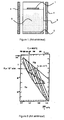
- a slice 1 of MCT and liquid mercury 2 are placed in a sealed ampoule 3.
- the ampoule 3 is then subjected to a predetermined, uniform and constant annealing temperature, generated by heating means 4, disposed around the bulb 3.
- the liquid mercury 2 is disposed in the lower part of the bulb 3 c i.e. the opposite of the MCT slice 1. It is vaporized and vapor phase mercury is applied to MCT slice 1.
- the annealing temperature is maintained during a predetermined annealing time until the gaps in the crystal lattice of the MCT wafer 1 are filled by the mercury vapor phase 5.
- the amount of liquid mercury 2 introduced into the ampoule 3 is calculated very precisely to match the desired charge carrier density.
- the pressure P r will be 10 -1 atm (1.01325.10 4 Pa) according to the phase equilibrium diagram of the figure 2 .
- the amount of liquid mercury 2 to be introduced into the ampoule 3 is then weighed exactly before being introduced into the ampoule 3.
- the ampoule 3 is then sealed.
- the weighing of liquid mercury 2 is often subject to errors with uncertainties which rise in mass generally to a few percent by weight. These uncertainties vary the annealing pressure P r of significantly and, consequently, the doping rate. Doping from such a device is not very reproducible and lacks precision. In addition, the pressure difference between the actual pressure obtained in the bulb 3 and the theoretical pressure is observed only once the thermodynamic equilibrium reached. This error can then be corrected by breaking the bulb 3 and repeating the weighing operation, sealing the bulb 3 and annealing to obtain the desired annealing pressure P r .
- the weighing of the liquid mercury 2 before loading into the ampoule 3 is often the source of contamination.
- the precise weighing of liquid mercury 2 requires several manipulations, conventionally, with a syringe and a spatula, to adjust the weighing. These successive manipulations can induce counter-doping or unwanted doping of the MCT slice 1.
- the document US Patent 3723190 describes, in particular, a process for the preparation of MCT of formula Hg 1-x Cd x Te (with 0 ⁇ x ⁇ 1) n-type from a p-type Hg 1-x Cd x Te material subjected to a temperature gradient.
- the heat treatment comprises a first treatment at a temperature below the temperature of the MCT solidus to obtain a homogeneous material and then a second treatment in the presence of an excess of mercury in order to adjust the stoichiometry of the material and, consequently, the type conductivity.
- the second heat treatment reduces the free electron concentration in the n-type material or converts the p-type material to the n-type. Nevertheless, the excess of mercury present throughout the second heat treatment fixes a part of the constituent elements of the MCT wafer and causes the dissolution or precipitation of these elements via the gas phase of mercury. This side effect affects the quality of doping.
- the purpose of the invention is to provide a chamber for annealing a type II-VI semiconductor material that overcomes the drawbacks of the prior art.
- the invention aims to provide an enclosure for doping semiconductor material type II-VI in a precise, reproducible and reliable, while reducing the risk of contamination.
- the invention also aims a device for annealing a type II-VI semiconductor material comprising this enclosure and a method of annealing in the presence of a group II element of the periodic table using such a device.
- this object is achieved by an enclosure, an annealing device and an annealing method according to the appended claims.
- the annealing device of a type II-VI semiconductor material in the presence of a group II element of the periodic table comprises an enclosure 7 for annealing the type II-VI semiconductor material, means for heating 6a and 6b and means for controlling the heating temperature.
- the chamber 7 is particularly suitable for the annealing of cadmium telluride and mercury (HgCdTe) as a semiconductor material of type II-VI.
- Cadmium mercury telluride is a compound of the general formula Hg 1-x Cd x Te where x is strictly between 0 and 1 (0 ⁇ x ⁇ 1).
- the group II element of the periodic table is advantageously mercury.
- Mercury has the advantage of having a very low steam partial pressure compared to the other elements of group II of the periodic table.
- CdTe CdTe
- GaAs GaP
- InP having an adjustable doping by annealing under steam pressure of one of their element
- the type II-VI semiconductor material is cadmium telluride and mercury and the element of group II of the periodic table is liquid mercury 2 at room temperature.
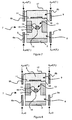
- the chamber 7 has a first zone 8 for storing the liquid mercury 2 and a second zone 9 for receiving the MCT.
- the latter is conventionally in the form of a slice of MCT.
- a grid 11 fixed to the internal walls of the enclosure 7 makes it possible to support the slice 10 of MCT while exposing the maximum area of the MCT.
- the enclosure 7 further comprises a partition wall 12 at an intermediate zone 13.
- the partition wall 12 is provided with a through hole 14 provided with a non-return flow member 15. gas to ensure the unidirectional passage of vapor phase mercury 5, from the first zone 8 to the second zone 9.
- the partition wall 12 delimits the volumes V 1 and V 2 , respectively corresponding to the first zone 8 and the second zone 9.
- the non-return gas flow member 15 may consist of a non-return valve, preferably a ball check valve ( figure 3 ).
- the non-return gas flow member 15 may be constituted by a mechanical system whose opening and / or closing is triggered manually.
- the chamber 7 has, advantageously, an internal section, reduced at the intermediate zone 13.
- the chamber 7 is preferably made of quartz, for example a quartz bulb, having a constriction at the intermediate zone 13 This structural characteristic makes it possible to reduce heat exchange between the first and second zones 8 and 9, respectively.
- the wall of the enclosure 7 preferably comprises a thermal insulation 16 at the intermediate zone 13.
- the first and second zones 8 and 9 are thermally insulated from each other.
- the entire circumference of the enclosure 7 may, for example, be surrounded at the intermediate zone 13 by rock wool constituting the thermal insulation 16.
- the chamber 7 advantageously comprises a sealing and sealing element 17 (at the upper part on the figure 3 ) which ensures the hermetic closure of the chamber 7.
- the chamber 7 can be subjected to a reduced pressure, after loading of the liquid mercury 2 in the first zone 8 by evacuation of the chamber 7, before closure of the enclosure 7 by sealing the sealing and sealing element 18.
- volume V 2 of the second zone 9 is delimited at its upper part by the sealing and sealing element 17, by the side walls of the enclosure 7 and at its lower part by the partition wall 12 and the non-return ball valve 15.
- the device for annealing a slice 10 of MCT in the presence of liquid mercury 2 comprises the enclosure 7, the heating means 6a and 6b, and control means, not shown, for controlling the heating temperature of the first zone 8 and the second zone 9, independently of one another.
- MCT slices 10 may be placed in the second zone 9 next to one another or one above the other on grids 11 spaced from one another.
- the heating means (6a and 6b on the figure 3 ) are used to independently heat the first and second zones, respectively 8 and 9, and maintain them at the same or different temperatures.
- control signals A 1 control the heating means 6a of the first zone 8
- control signals A 2 independently control the heating means 6b of the second zone 9.
- the heating means 6a and 6b may be constituted by at least two heating means respectively covering the first and second zones 8 and 9.
- Each heating means advantageously surrounds the entire circumference of the enclosure 7 around the zone corresponding, in order to obtain a homogeneous temperature.
- the heating means are arranged so that a constant and uniform temperature can be obtained in each of the zones 8 and 9 and in the intermediate zone 13. The presence of cold point must be avoided in order to prevent any condensation within the atmosphere. enclosure 7.
- the regulation of the temperature of the heating means, by the control means, also makes it possible to control the temperature gradients in the enclosure 7 by simultaneously and / or consecutively heating the first zone 8 and the second zone 9.
- the thermal insulation 16 minimizing the heat exchange between the first zone 8 and the second zone 9 improves the control of the heating and / or cooling the first and second zones, respectively 8 and 9.
- the heating means 6a and 6b and the means for controlling the heating temperature of the first zone 8 and the second zone 9, independently of one another, are advantageously constituted by a bizone oven.
- the doping of a II-VI type 10 semiconductor material in the presence of a group II element of the periodic table 2 is carried out according to an annealing method using the annealing device described above.
- the method comprises a first step of charging liquid mercury 2 at room temperature in the first zone 8 of the annealing device. During this step, the sealing and sealing element 17 is disengaged from the enclosure 7 to allow access to the first zone 8.
- an excess of liquid mercury 2 is used to supply the enclosure 7 with a doping element.
- the excess takes into account the amount of mercury 2 calculated from equation (3) above, the amount required to obtain a determined doping level of a slice of MCT.
- the doping level is a number of moles n vapor phase mercury r 5 in a volume V 2 defined in the second zone 9.
- a number of moles n r equal to 1.44 ⁇ 10 -3 mol
- a pair (T r , P r ) corresponding respectively to 400 ° C.
- the quantity of liquid mercury 2 necessary for obtaining a doping rate of 10. 17 at.cm -3 is 289 mg of mercury.
- Practically, commercially available pre-sold liquid mercury ampoules 2 can be used.
- the conditioning ampoules are then chosen to allow the introduction into the first zone 8 of the ampoule 7 of a quantity of liquid mercury 2 in excess, that is to say greater than 300 mg, preferably much greater than this value.
- the liquid mercury 2 is advantageously transferred from its initial conditioning ampoule to the first zone 8 of the chamber 7. This transfer is carried out without any manipulation or contact with objects that may be a source of liquid mercury contamination 2.
- the non-return gas flow member is a ball check valve
- the charging of the liquid mercury 2 is performed after the ball check valve 15 has been withdrawn from its housing to release the orifice. passage 14 ( figure 4 ).
- the ball check valve 15 is then replaced in its housing to close the passage opening 14.
- the slice 10 of MCT is disposed on the gate 11 and the enclosure 7 is evacuated, so to apply a pressure close to zero in the chamber 7.
- the vacuum is carried out according to any known method.
- the enclosure 7 can be placed in a vacuum chamber not shown.
- the chamber 7 prior to evacuation, the chamber 7 is cooled with liquid nitrogen to freeze the mercury during the pumping step.
- the sealing and / or sealing member 17 is then repositioned so as to make the enclosure 7 hermetic, for example by sealing.
- the heating means are controlled manually or by automatic programming by the means for controlling the heating temperature of the first zone 8 and the second zone 9, independently of one another.
- the first zone 8 and the second zone 9 are then heated to the same predetermined temperature T 1 , either simultaneously or successively, to cause the passage of mercury in the vapor phase 5 from the first zone 8 to the second zone 9 ( figure 6 ).
- the temperature T 1 is calculated to obtain a number of moles of mercury n r determined in the second zone 9.
- This number of moles n r refers to the vapor phase mercury doping level of a MCT wafer 10 having a known stoichiometry, at a given volume.
- the number of moles n r corresponds to a desired charge carrier density for the pair (T r , P r ) determined according to the diagram represented in FIG. figure 2 .
- the pair (T r , P r ) (400 ° C, 10 -1 atm) is selected for a charge carrier density of 10 17 at.cm -3 .
- the temperature T 1 is determined from the known liquid / vapor phase change diagram of the mercury represented in FIG. figure 9 (Clapeyron's law). At thermodynamic equilibrium, the vapor phase mercury is in equilibrium with the liquid mercury 2 and the vapor partial pressure P v of the mercury corresponds to the saturation vapor pressure P vs mercury.
- n r By plotting this value n r on the curve of the diagram of the figure 10 a temperature T 1 of 242 ° C is determined.
- This temperature of 242 ° C. corresponds to the temperature to which the enclosure 7, and more particularly the first zone 8 and the second zone 9, must be subjected for the partial pressure of mercury vapor P v , to thermodynamic equilibrium. , equal to the saturation vapor pressure P vs.
- the number of moles n r of mercury in the vapor phase is equal to 1.44 ⁇ 10 -3 moles for a volume V 2 of the second zone 9 of 8 ⁇ 10 -4 m 3 .
- the vapor phase mercury emitted in the first zone 8 lifts the ball check valve 15 and enters the second zone 9.
- the heating of the first and second zones at the same temperature T 1 causes the passage of the vapor phase mercury 5 from the first zone 8 to the second zone 9 until the partial pressure of the vapor P v of mercury in the entire chamber 7 reaches a value corresponding to the saturation vapor pressure P vs mercury for a desired doping level.
- the temperature is advantageously homogeneous so as to avoid the presence of cold spots, in particular in the intermediate zone 13.
- the chamber 7 may possibly be moved in the oven, during heating, to prevent the formation of cold spots located in the enclosure 7, resulting in the condensation of the mercury.
- the vapor phase mercury 5 is in equilibrium with the excess liquid mercury 2 and fills the entire chamber 7.
- the pressure in the chamber 7 is then equal to the saturation vapor pressure P vs mercury.
- the pressure is homogeneous in the first and second zones, respectively 8 and 9.
- the ball check valve 15 then falls back into its housing closing the passage opening 14.
- the slice 10 of MCT is then subjected to annealing by heating at least the second zone 9 to the annealing temperature T r , greater than T 1 .
- the annealing temperature T r defines the annealing pressure P r in a given volume ( figure 2 ).
- Mercury vapor 5 present in the second area 9 contains a number of moles of mercury n r calculated according to equation (3) corresponding to the torque (T r, P r).
- the heating of the first zone 8 is interrupted during the annealing step.
- the first zone 8 is cooled to a temperature below T 1 so as to improve the sealing of the ball check valve 15.
- the intermediate zone 13 is preferably at the temperature T 1 to prevent the formation of cold spots in the volume V 2 .
- the T r annealing temperature is maintained during annealing time typically of the order of several days necessary to achieve the desired doping level.
- a quartz bulb 7 with a diameter of 10 cm has a first zone 8 of 10 cm in height and a second zone 9 of 10 cm in height provided with a grid 11 on which is positioned a slice of Hg 0.8 Cd 0.2 Te of 10 microns thick for a surface of 36mm x 38mm.
- the ampoule 7 is filled with 5 g of liquid mercury 2 directly transferred from a conditioning ampoule.
- the intermediate zone 13 has an internal section, reduced by 1.5 cm and by 5 cm in height.
- the quartz separating partition 12 supports the quartz ball check valve 15, 1 cm in diameter.
- the bulb 7 is cooled with liquid nitrogen and placed under vacuum until a pressure of 0.1 Pa is reached.
- the ampoule 7 is hermetically sealed by sealing a quartz stopper 18 with a torch.
- the bulb 7 is then placed in a bizone halogen lamp oven marketed by the company AET Technologies, then heated according to a programmed temperature gradient.
- the first zone 8 and the second zone 9 are first heated to a temperature T 1 of 241.3 ° C until the thermodynamic equilibrium.
- the second zone 9 is heated to an annealing temperature T r of 400 ° C. for 1 day.
- the heating of the first zone 8 is interrupted during the annealing step.
- the density of the charge carriers obtained is 10 17 at.cm -3 .
- a variation of temperatures T 1 and / or T r leads a modification of n r and / or of the pressure P r and thus of the doping rate. Thanks to this annealing device, the doping of type II-VI semiconductor materials can thus be achieved solely from the control and adjustment of the temperature.
- the error margin on the number of moles ⁇ n is 10. -5 mole or 0.14% against some percent in the case of weighing.
- the gain is therefore greater than a factor of 10.
- the annealing device described above is effective and makes it possible to dispense with manipulations that may affect the quality of type II-VI semiconductor materials doped during the heat treatment. Moreover, unlike the manufacturing processes of the prior art, the annealing method according to the invention, based on the control and adjustment of the temperatures T 1 and T r is easy to implement, flexible and guarantees control doping rate with excellent reproducibility and a very low contamination rate.
Landscapes
- Crystals, And After-Treatments Of Crystals (AREA)
Applications Claiming Priority (1)
| Application Number | Priority Date | Filing Date | Title |
|---|---|---|---|
| FR0902560A FR2946184B1 (fr) | 2009-05-27 | 2009-05-27 | Enceinte, dispositif et procede de recuit d'un materiau semi-conducteur du type ii-vi |
Publications (2)
| Publication Number | Publication Date |
|---|---|
| EP2256784A2 true EP2256784A2 (de) | 2010-12-01 |
| EP2256784A3 EP2256784A3 (de) | 2017-03-22 |
Family
ID=41727565
Family Applications (1)
| Application Number | Title | Priority Date | Filing Date |
|---|---|---|---|
| EP10354022.5A Withdrawn EP2256784A3 (de) | 2009-05-27 | 2010-05-18 | Gehaüse, Vorrichtung und Verfahren zum Glühen von einem II-IV Halbleitermaterial |
Country Status (4)
| Country | Link |
|---|---|
| US (1) | US8377212B2 (de) |
| EP (1) | EP2256784A3 (de) |
| JP (1) | JP5631633B2 (de) |
| FR (1) | FR2946184B1 (de) |
Families Citing this family (3)
| Publication number | Priority date | Publication date | Assignee | Title |
|---|---|---|---|---|
| FR2946184B1 (fr) * | 2009-05-27 | 2011-07-01 | Commissariat Energie Atomique | Enceinte, dispositif et procede de recuit d'un materiau semi-conducteur du type ii-vi |
| US9419170B2 (en) * | 2014-02-06 | 2016-08-16 | Alliance For Sustainable Energy, Llc | Controlling the stoichiometry and doping of semiconductor materials |
| CN114551642B (zh) * | 2022-02-10 | 2023-09-12 | 中国科学院上海技术物理研究所 | 一种弱p型碲镉汞材料的退火方法 |
Citations (2)
| Publication number | Priority date | Publication date | Assignee | Title |
|---|---|---|---|---|
| US3723190A (en) | 1968-10-09 | 1973-03-27 | Honeywell Inc | Process for preparing mercury cadmium telluride |
| JPH09326404A (ja) | 1996-06-06 | 1997-12-16 | Fujitsu Ltd | HgCdTe結晶の製造方法 |
Family Cites Families (17)
| Publication number | Priority date | Publication date | Assignee | Title |
|---|---|---|---|---|
| US4028145A (en) * | 1975-10-29 | 1977-06-07 | Honeywell Inc. | Stoichiometric annealing of mercury cadmium telluride |
| US4439267A (en) * | 1982-09-29 | 1984-03-27 | The United States Of America As Represented By The Secretary Of The Army | Vapor-phase method for growing mercury cadmium telluride |
| GB8324531D0 (en) | 1983-09-13 | 1983-10-12 | Secr Defence | Cadmium mercury telluride |
| GB2156857B (en) * | 1983-11-30 | 1987-01-14 | Philips Electronic Associated | Method of manufacturing a semiconductor device |
| JPS6263421A (ja) * | 1985-09-13 | 1987-03-20 | Toshiba Corp | 半導体ウエ−ハ熱処理装置 |
| US5079610A (en) * | 1985-12-05 | 1992-01-07 | Santa Barbara Research Center | Structure and method of fabricating a trapping-mode |
| US5182217A (en) * | 1985-12-05 | 1993-01-26 | Santa Barbara Research Center | Method of fabricating a trapping-mode |
| JPS63117987A (ja) * | 1986-11-05 | 1988-05-21 | Sumitomo Electric Ind Ltd | 濃度均一化用坩堝 |
| JP2746497B2 (ja) * | 1992-03-03 | 1998-05-06 | 三菱電機株式会社 | 半導体装置の製造方法 |
| JPH07193003A (ja) * | 1992-08-19 | 1995-07-28 | Fujitsu Ltd | 気相成長装置および気相成長方法 |
| JPH0697080A (ja) * | 1992-09-10 | 1994-04-08 | Mitsubishi Electric Corp | 化学気相成長装置用反応室および該反応室を用いた化学気相成長装置 |
| JPH07118097A (ja) * | 1993-10-25 | 1995-05-09 | Fujitsu Ltd | HgCdTe結晶のp型キャリア濃度制御方法およびホトダイオードの製造方法 |
| JPH10311207A (ja) * | 1997-05-13 | 1998-11-24 | Tanaka Hisayoshi | 水銀発電装置 |
| JP3644011B2 (ja) * | 1999-05-14 | 2005-04-27 | 富士通株式会社 | 化合物半導体結晶のドーピング方法 |
| FR2946184B1 (fr) * | 2009-05-27 | 2011-07-01 | Commissariat Energie Atomique | Enceinte, dispositif et procede de recuit d'un materiau semi-conducteur du type ii-vi |
| CN103118607B (zh) * | 2010-07-16 | 2015-09-23 | 伊西康内外科公司 | 将胆汁从胆囊引导至肠内的装置 |
| DE102011012548A1 (de) * | 2011-02-26 | 2012-08-30 | Robert Bosch Gmbh | Ventil und Verfahren zu dessen Herstellung |
-
2009
- 2009-05-27 FR FR0902560A patent/FR2946184B1/fr active Active
-
2010
- 2010-05-18 EP EP10354022.5A patent/EP2256784A3/de not_active Withdrawn
- 2010-05-27 US US12/788,650 patent/US8377212B2/en not_active Expired - Fee Related
- 2010-05-27 JP JP2010121300A patent/JP5631633B2/ja not_active Expired - Fee Related
Patent Citations (2)
| Publication number | Priority date | Publication date | Assignee | Title |
|---|---|---|---|---|
| US3723190A (en) | 1968-10-09 | 1973-03-27 | Honeywell Inc | Process for preparing mercury cadmium telluride |
| JPH09326404A (ja) | 1996-06-06 | 1997-12-16 | Fujitsu Ltd | HgCdTe結晶の製造方法 |
Non-Patent Citations (1)
| Title |
|---|
| "Electrical Doping Of HgCdTe by Ion Implantation and Heat Treatment", JOURNAL OF CRYSTAL GROWTH, 1988, pages 700 - 722 |
Also Published As
| Publication number | Publication date |
|---|---|
| FR2946184B1 (fr) | 2011-07-01 |
| JP5631633B2 (ja) | 2014-11-26 |
| EP2256784A3 (de) | 2017-03-22 |
| JP2010283345A (ja) | 2010-12-16 |
| FR2946184A1 (fr) | 2010-12-03 |
| US20100304576A1 (en) | 2010-12-02 |
| US8377212B2 (en) | 2013-02-19 |
Similar Documents
| Publication | Publication Date | Title |
|---|---|---|
| EP2256784A2 (de) | Gehaüse, Vorrichtung und Verfahren zum Glühen von einem II-IV Halbleitermaterial | |
| US4642142A (en) | Process for making mercury cadmium telluride | |
| EP1022772A1 (de) | CdTe KRISTALL ODER CdZnTe KRISTALL UND VERFAHREN ZUR HERSTELLUNG DIESES KRISTALLES | |
| US4357620A (en) | Liquid-phase epitaxial growth of cdTe on HgCdTe | |
| Capper | Bridgman growth of CdxHg1− xTe—A review | |
| US3485685A (en) | Method and source composition for reproducible diffusion of zinc into gallium arsenide | |
| US7641733B2 (en) | Method and apparatus for growth of multi-component single crystals | |
| CN117026378A (zh) | SiC外延晶片及SiC器件 | |
| JP4022997B2 (ja) | 3−5族化合物半導体結晶へのZn拡散方法及び拡散装置 | |
| EP2581475A1 (de) | Verfahren zur Herstellung von p-dotiertem Zinkoxyd ZnO oder von p-dotiertem ZnMgO | |
| US4105472A (en) | Preparation of silicon doped mercury cadmium telluride | |
| US4105477A (en) | Doping of (hg,cd)te with a group va element | |
| EP0787839B1 (de) | Verfahren zum Kalibrieren der Temperatur eines Epitaxiereaktors | |
| TWI879820B (zh) | 固體攝像元件用之矽單晶基板及矽磊晶晶圓以及固體攝像元件 | |
| JP4172184B2 (ja) | 半導体基板への亜鉛拡散方法、半導体基板の加熱方法。 | |
| Capper | Narrow bandgap II-VI semiconductors: Growth | |
| Norton et al. | Scale-up of LPE processes for flexibility in manufacturing | |
| US4950358A (en) | Vapor phase epitaxy of semiconductor material in a quasi-open system | |
| JPH0793277B2 (ja) | InP基板中へのCd拡散方法 | |
| RU2686523C1 (ru) | Способ легирования цинком подложек или слоев фосфида индия | |
| JPH0132653B2 (de) | ||
| EP2363515A1 (de) | Herstellungsverfahren eines kristallisierten Halbleitermaterials | |
| JPS5917846B2 (ja) | 3↓−5化合物半導体への不純物の拡散方法 | |
| JP2700123B2 (ja) | HgCdTeの液相エピタキシヤル成長方法及びその装置 | |
| Capper | MCT materials aspects |
Legal Events
| Date | Code | Title | Description |
|---|---|---|---|
| PUAI | Public reference made under article 153(3) epc to a published international application that has entered the european phase |
Free format text: ORIGINAL CODE: 0009012 |
|
| AK | Designated contracting states |
Kind code of ref document: A2 Designated state(s): AL AT BE BG CH CY CZ DE DK EE ES FI FR GB GR HR HU IE IS IT LI LT LU LV MC MK MT NL NO PL PT RO SE SI SK SM TR |
|
| AX | Request for extension of the european patent |
Extension state: BA ME RS |
|
| PUAL | Search report despatched |
Free format text: ORIGINAL CODE: 0009013 |
|
| AK | Designated contracting states |
Kind code of ref document: A3 Designated state(s): AL AT BE BG CH CY CZ DE DK EE ES FI FR GB GR HR HU IE IS IT LI LT LU LV MC MK MT NL NO PL PT RO SE SI SK SM TR |
|
| AX | Request for extension of the european patent |
Extension state: BA ME RS |
|
| RIC1 | Information provided on ipc code assigned before grant |
Ipc: H01L 21/67 20060101AFI20170213BHEP |
|
| STAA | Information on the status of an ep patent application or granted ep patent |
Free format text: STATUS: THE APPLICATION HAS BEEN PUBLISHED |
|
| STAA | Information on the status of an ep patent application or granted ep patent |
Free format text: STATUS: THE APPLICATION IS DEEMED TO BE WITHDRAWN |
|
| 18D | Application deemed to be withdrawn |
Effective date: 20170923 |