EP2256253B1 - Installation à séparateur dotée d'un réservoir séparateur - Google Patents
Installation à séparateur dotée d'un réservoir séparateur Download PDFInfo
- Publication number
- EP2256253B1 EP2256253B1 EP20100005387 EP10005387A EP2256253B1 EP 2256253 B1 EP2256253 B1 EP 2256253B1 EP 20100005387 EP20100005387 EP 20100005387 EP 10005387 A EP10005387 A EP 10005387A EP 2256253 B1 EP2256253 B1 EP 2256253B1
- Authority
- EP
- European Patent Office
- Prior art keywords
- container
- valve
- separating
- opening
- valve seat
- Prior art date
- Legal status (The legal status is an assumption and is not a legal conclusion. Google has not performed a legal analysis and makes no representation as to the accuracy of the status listed.)
- Not-in-force
Links
Images


Classifications
-
- E—FIXED CONSTRUCTIONS
- E02—HYDRAULIC ENGINEERING; FOUNDATIONS; SOIL SHIFTING
- E02D—FOUNDATIONS; EXCAVATIONS; EMBANKMENTS; UNDERGROUND OR UNDERWATER STRUCTURES
- E02D29/00—Independent underground or underwater structures; Retaining walls
- E02D29/12—Manhole shafts; Other inspection or access chambers; Accessories therefor
- E02D29/14—Covers for manholes or the like; Frames for covers
- E02D29/1436—Covers for manholes or the like; Frames for covers with overflow or explosion control means, e.g. check or relief valves
-
- E—FIXED CONSTRUCTIONS
- E03—WATER SUPPLY; SEWERAGE
- E03F—SEWERS; CESSPOOLS
- E03F5/00—Sewerage structures
- E03F5/14—Devices for separating liquid or solid substances from sewage, e.g. sand or sludge traps, rakes or grates
Definitions
- a stream is understood to mean a mixture of liquid, if appropriate, with suspended solids and / or solids.
- such a mixture is also referred to as a liquid for the sake of simplification, since the liquid is the main component of the substance flow in question, whereby the presence of suspended matter and / or solids in the mixture designated as liquid is not excluded.
- the invention relates in particular to fixed, usually buried or under a traffic surface located flow tanks or containers such as. Silos, tanks or earth tanks of a separator device.
- Such containers in particular for the treatment of problem or dirty water, in which in particular liquids, solids or suspended solids are separated from the liquid or wastewater, must be freed from time to time by the accumulated in the container said substances, which usually about an opening or a manhole is made at the top of the container.
- the level of the liquid present in the container during normal operation is determined by a predetermined drainage level of the container.
- the effluent from the container drained liquid can run to a collection system for supply to a wastewater treatment plant.
- the drain level in the tank is offset at a safe distance from the tank opening.
- the container opening of the separator tank is located significantly below, for example, a trafficable traffic area, e.g. up to several meters.
- a trafficable traffic area e.g. up to several meters.
- a space for access is provided from above to the container opening.
- a so-called chess neck is created for example by successive rings.
- the free space in the shaft neck is to be separated from the surrounding earth.
- the end cap is laid on top of the chute neck.
- the object of the present invention is to provide a separator system in which a separator container is secured against undesired entry of a foreign substance.
- a separator container is secured against undesired entry of a foreign substance.
- the invention is based on a separator system comprising a separator container with a container opening at the top in the separator container, which is above a liquid level in the separator container which settles when liquid flows into the separator container via a feed during normal operation of the separator container and out of the separator container via a drain flows away, wherein above the container opening, a construction arrangement with a closable construction opening adjoins, so that in a closed philosophicalöffung the assembly separates an area above the separator from surrounding areas and open container opening is accessible from above the container opening.
- the separator is, for example, a light liquid or sludge and light liquid separator.
- the essence of the invention is that a device for securing the separator container against unwanted ingress of foreign liquid is provided in the separator through the container opening with a closure device for the container opening, wherein the container opening with the closing device against passage of liquid through the container opening is securable ,
- the container opening can be improved with respect to critical operating conditions in such a way that undesired ingress of liquid from the assembly arrangement through the container opening into the container can be absolutely reliably avoided. An increase in the liquid level in the container via a corresponding critical or maximum absorption capacity can thus not occur.
- the closing device is designed as a valve arrangement.
- a main purpose of the container opening in its present manner is directed to a regular inspection of the container interior by a person and / or a suction or removal of a substance collected in the container from the outside via an access section or the chess neck. These measures remain unimpaired by the closing device or valve arrangement according to the invention.
- the valve assembly is particularly designed so that it can be removed as needed and / or adjusted to allow the intended use of the container opening, for example, as if no valve assembly available.
- a three-part basic structure In separator systems and the like, in particular a three-part basic structure is known.
- the possibly provided with a sludge trap container or separator body itself is usually constructed monolithic and tested by the manufacturer, in particular on tightness of the walls and mechanical stability.
- at least one connection or mounting part can be present, for example an annular component which is reliably sealed with seals to the adjacent container body and which also remains permanently tight, since it is not exposed to any critical mechanical stresses in the installed state.
- a chess neck with equalizing rings or shaft-forming rings is provided in almost all cases up to a surface or traffic area.
- the separator container comprises a connection or construction part or manhole.
- the shaft closure may, for example, comprise a manhole cover which fits onto an opening in the traffic area closing off at the top.
- the chute neck is due to the height to be bridged or the external loads from the critical part in terms of system leaks.
- the near-surface area of the compensating rings with the manhole cover can be affected by eg traffic and frost effect, etc. gets leaky with time. Even with unaffected manhole, it is not possible that, for example, in strongly rising surface water or flood the manhole cover or the area of the compensating rings is absolutely tight.
- liquid entering the chute neck can enter the container via the container opening and thus extraneous water can lead to an increase in the liquid in the container or separator with the problems explained above.
- valve arrangement With a valve arrangement according to the invention these problems are prevented.
- the system components can be designed as before and modified accordingly or advantageously existing systems can also be retrofitted on site with a valve arrangement according to the invention.
- a corresponding sludge trap or separator system including body parts can thus be legal or e.g. Fully comply with DIN specifications.
- the container or the entire arrangement can be absolutely sure, especially in flood, heavy rain or flood situations against leakage of critical substances from the container into the environment to be protected if the container also has an inlet and backstop.
- the valve arrangement can be realized from the basic structure in many different configurations, for example automatically as a shut-off valve or as a safety valve. Particularly simple and robust, a flap valve can be used.
- the closing device is designed such that in the case of liquid protruding above the container opening outside the container, the closing device automatically blocks the passage of liquid through the container opening.
- a self-closing valve such as a particularly simple and robust flapper valve
- passage for liquid from the throat into the container can be prevented at precisely the time critical situations occur.
- the valve assembly may be in a different switching state. It is thereby achieved that the valve arrangement then closes when extraneous water penetrates into the shaft neck. It is not excluded that the valve assembly is designed so that it already closes safely in time, before extraneous water is present at this. The foreign water kept away from the container interior can accumulate above the valve arrangement in the shaft neck.
- the closing device is designed to allow a gas exchange between the interior of the container and the area above the container when no liquid is present outside the container above the container opening.
- a gas exchange or air exchange can be ensured at least from the interior of the container to the outside.
- This is advantageous with regard to a critical gas composition in the container region above the drainage level or a possible danger of explosion due to a corresponding air-gas mixture in the container above the liquid level.
- the floating light liquid such. Pass gasoline through its comparatively low vapor pressure in such quantities in the overlying gas phase and mix with existing air oxygen that an explosive gas-air mixture is present.
- valve arrangement can be designed so that the gas or gas-air mixture can escaped outwards into the throat.
- provision must be made that e.g. When opening the manhole cover a ventilation of the manhole takes place in order to exclude an explosion there.
- valve arrangement comprises a valve seat arranged in a positionally fixed manner and a movable valve body cooperating with the valve seat, wherein the valve seat comprises a flat material angled in cross-section.
- valve seat is designed as a mechanically robust and easy-to-mount angled flat material, for example as a continuous circumferential round or polygonal profile steel frame, for example in section angular, T or U-shaped, each with a free leg directed upwards forms the actual valve seat, which cooperates with the valve body.
- both free legs may form the valve seat, for example, oriented upwardly for providing two sealing lines.
- the valve arrangement has a valve body designed to be movable against a valve seat, wherein in the closed valve arrangement, if there is no liquid outside of the separator tank above the closing device, the valve body on the valve seat is tight only by the weight of the valve body and gas exchange is possible by the valve body can lift off the valve seat.
- the valve assembly can be made simple and robust.
- the container opening can be opened at any time or immediately without further measures or aids by a person, in particular by hand, for example in the case of an inspection of the separator system.
- the valve body is advantageously particularly simple. In particular, since the valve body is present in a harsh environment in the manhole area and z. B. is exposed to changing temperatures and / or humidity or is subject to corrosion. A simply designed valve body is therefore a prerequisite for its optimal functioning. It is particularly advantageous if the valve assembly or the valve body is formed without additional elements such as closing means or spring means for applying an additional closing force.
- valve body is lid-like, on which a sealing portion of a sealing material is present, which comes to provide a sealing effect with the valve seat in abutment.
- This can be particularly effective over the sealing portion or the nature and design of the sealing material at an example. formed as a cover element valve body, the sealing effect in the interaction of the sealing portion are influenced and optimized with the valve seat.
- valve body is movably received via a pivot axis relative to the valve seat movable.
- pivoting the valve body it can be defined or brought exactly and as often repeatable in a closed position with the valve assembly closed and back to an open position. This is advantageous for a tight fit of the valve body on the valve seat.
- the valve body can be captively received via the pivot axis connection.
- valve body In addition to a pivot bearing and other types of storage of the valve body are advantageously possible, for example, a sliding bearing with a sliding seat of the valve body.
- the valve body may be designed separately and formed separately from the valve seat. Thus, the valve body is not mounted on the valve seat or adjacent sections. This can possibly be particularly space-saving.
- valve assembly is thus possibly easier to train.
- the valve seat is designed as a closed frame, which is positioned in the region of the container opening or an extension of the container opening, in particular in the area around the container opening is positioned around. This can be achieved that the entire container opening is acted upon by the valve assembly or no gap in terms of the sealing effect of Valve arrangement with respect to the container opening occurs.
- the valve assembly is present outside a region formed by the clear width of the container opening or its extension.
- the accessibility or the mounting and the available space is advantageous with respect to an arrangement of the valve arrangement present on the inside of the container in the container opening, which is in principle not excluded.
- valve arrangement may be present within a region formed by a clear width of the passage opening.
- the container opening may be suitable, in particular in the case of a depth of the container opening extending in the passage direction, to completely or almost completely accommodate the valve arrangement, which is particularly space-saving.
- the valve assembly may be at least largely accommodated or recessed in the container opening without projecting substantially beyond the container opening.
- valve seat is provided on a mounting part which is formed on the container and which adjoins the container opening.
- the valve seat and thus the valve assembly can be positioned over, for example, a mounting ring provided on the container, e.g. is designed as a separate component.
- a mounting ring provided on the container, e.g. is designed as a separate component.
- valve body of the valve assembly it is advantageous for example for the inspection of the container interior, that in the valve body of the valve assembly, an additional valve is present, which from outside the container with the valve assembly closed is operable.
- the likewise closed additional valve can be opened by actuation and the residual fluid quantity are discharged into the container when it is brought into a normal operating state or in particular no backflow prevails. Subsequently, the valve assembly can be opened and the container opening is freely accessible.
- FIGS. 1 to 8 are executed in a highly schematic manner, partly with the omission of individual components.
- the same reference numerals are sometimes used for corresponding parts.
- the container in question is not shown with a container opening for a liquid itself.
- the locking device according to the invention is according to Figure 1 to 7 arranged on an adjoining the container opening body part 2 with an opening 4, wherein the opening 4 connects directly to the container opening and is aligned therewith.
- FIG. 8 shows a separator system with inventive locking device above a container opening only schematically without further details z. B. a body part. It is not excluded that the locking device is also present directly on the container opening or in particular without body part.
- FIG. 1 schematically shows a designed as a valve assembly 1 Sch healthyeinrichzung invention.
- the valve arrangement 1 is arranged on the built-up part 2, which is installed above a separator or sludge trap, not shown.
- the body part 2, which is also referred to as a cover plate, can be designed, for example, as an annular body 3 made of concrete, which does not have an opening 4 for access from outside or upwards into the interior of the body Having shown separator.
- the opening 4 in particular has the same diameter as the container opening, not shown.
- the separator system, not shown, with a separator tank can follow below the body part 2.
- the body part 2 is arranged with appropriate seals or other measures close to the separator.
- a cleaning and / or control opening on the separator container is extended upward via the opening 4.
- FIG. 1 shown arrangement close to elements of a chess neck, in particular compensating rings, so that upwards an opening is provided in the underlying chess neck area.
- This opening is closed by a corresponding arrangement, in particular a seated in a receiving ring manhole cover.
- the manhole cover with receiving ring is often part of a traffic area and correspondingly heavily loaded mechanically. Therefore, this arrangement is often not permanently sealed, so that again and again, especially in heavy rain or flood situations, water can penetrate into the manhole area and into the separator from above.
- the valve arrangement 1 has a cover-like, for example, round disk-shaped cover element 5.
- the cover 5 is pivotally movable relative to the mounting part 2 and an annular valve seat 8 of the valve assembly 1 fixed thereto via a hinge arrangement 6 which provides a pivot axis S for the cover element 5.
- the cover element 5, which is designed, for example, as a plastic or steel element, will be through Dead weight in the in FIG. 1 shown closed valve assembly 1 with a corresponding contact force against the valve seat 8 pressed tightly.
- Cover member 5 is devisnalb the opening 4 and covers it completely sealed. In particular, the cover member 5 projects outwardly beyond an inner wall 4a of the opening 4.
- a closed around circumferential flat seal 7 is present at a directed to the opening 4 bottom 5a of the cover 5.
- the seal 7 may, for example, be glued to the underside 5 a and is formed, for example, of an elastomeric material, for example designed as a rubber flat ring.
- the valve seat 8 is designed here as a closed round frame made of steel, which is L- or T-shaped in section as a narrow support web for the seal 7 is used.
- valve assembly 1 In the state shown in accordance with FIG. 1 the valve assembly 1 is closed. If no accumulated water in the shaft neck above the valve assembly 1 is present, the cover 5 is only with its own weight on the valve seat 8.
- the valve arrangement 1 is designed in such a way that in this state a certain small gas exchange is possible via the sealing area formed with the seal 7 and the valve seat 8 or a valve seat web 8a.
- the cover 5 is possibly raised slightly and so a gas exchange made possible by the cover with the seal 7 briefly lifts off the valve seat web 8a.
- FIG. 2 the opened valve arrangement 1 is shown.
- the cover 5 is pivoted about 90 degrees about the pivot axis S counterclockwise, so that the opening 4 is freely accessible.
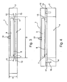
- FIG. 3 An alternative arrangement of the valve arrangement 1 according to the invention FIG. 3 , which has a Abheeileckel 9 with a handle member 10.
- the handle element 10 for example, manually from the top of the Abheeileckel 9 of the in FIG. 3 shown closed position or be placed back on a valve seat 8 which is mounted on an anchoring part 11.
- the anchoring part 11 is designed here as an inner diameter D of an opening 4 in the body part 2.
- the anchoring part 11 may have anchoring elements 12, 13, which engage in the structural part 2 for fixing the anchoring part 11 in this, for example, are cast.
- FIG. 3 It can be seen that advantageously a very space-saving arrangement of the valve arrangement 1 in the region of a height H of the body part 2 is possible.
- the valve assembly 1 is almost completely housed within the height H of the opening 4 in the forward direction.
- FIG. 4 Another inventive valve assembly 1 in an alternative arrangement shows FIG. 4 , In this case, the valve assembly 1 with a lift-off lid 9 according to the embodiment according to FIG. 3 designed.
- the Abheeileckel 9 also includes a handle member 10, arranged centrally on the upper side.
- valve seat receptacle 15 Above the body part 2 with the interposition of a circumferential rubber-round seal 14, a valve seat receptacle 15 is provided, which is followed by another mounting part 16 above.
- the valve seat receptacle 15 is firmly fixed to the body part 2 from above, greatly simplified indicated by a screw connection with a screw 17 and a dowel 18 in the body part 2.
- FIG. 4 at the valve seat seat 15 of the valve seat 8 available.
- FIG. 1 shows alternative arrangement with a pivotable cover 5 on a body part 2 in the closed state FIG. 5 ,
- the pivoting movement takes place about a hinge arrangement 6 about the pivot axis S.
- the valve arrangement comprises a seal 7, which cooperates with a valve seat 8.
- an additional valve 19 is formed, which serves to provide a self-closing opening in the cover 5, which allows improved gas exchange with the valve assembly 1 closed at not above the valve assembly 1 pending liquid.
- the closed additional valve 19 is shown.
- This comprises a downwardly conically tapered valve body 20.
- the valve body 20 is inserted in a correspondingly conical round hole, which serves as a valve seat 21.
- the valve seat 21 comprises a valve seat opening 21a provided centrally in the cover element 5.
- a pull cable 22 for acting on the valve body 20 is present at the top of the valve body 20.
- FIG. 7 shows the arrangement according to FIG. 5
- the valve body 20 when the auxiliary valve 19 is open, the valve body 20 is not accommodated fitting in the valve seat opening 21, so that over a remaining circular gap 23 an air exchange is possible. If fluid builds up in the chute neck above the cover element 5 due to the ingress of external water, the valve body 20 will be ejected from the in FIG. 7 shown open position by the hydrostatic pressure of the liquid pressed down. In this case, the valve body 20 reaches the position according to FIG. 5 and is firmly pressed into the valve seat opening 21a.
- an absolutely air- or water-tight closing of the additional valve 19 is ensured and it can also in a previously controlled via the open additional valve 19 possible gas exchange between Schachthals Scheme and container interior no extraneous water in the Container over the opening 4 penetrate.
- FIG. 6 shows the arrangement 'according to FIG. 5 with open cover 5, which is pivoted about the pivot axis S in the open position.
- open cover 5 which is pivoted about the pivot axis S in the open position.
- At the bottom of the valve body 20 also has a stop element 24 is present.
- the stop member 24 prevents complete withdrawal of the valve body 20 from the valve seat opening 21a by the stop member 24 abuts the underside of the cover 5 when pulling on the pull cable 22.
- FIG. 8 shows a highly schematic of a buried separator system 25 according to the invention, which comprises a separator tank 26 with a connection or mounting part designed as a structural arrangement 27, which is also referred to as a shaft neck.
- the separator system 25 is highly modified or schematized and simplified, partially omitting details, in particular in the interior of the separator tank 26.
- the separator tank 26 can be designed as a separate component, for example as a plastic container.
- the densely produced separator tank 26 according to FIG. 8 is formed of a separator body 28 with subsequent thereto top-up elements 29, 30.
- the separator body 28 and the structural elements 29 and 30 are interconnected absolutely tightly together.
- the upper structural element 30 tapers conically upwards and comprises a in the installed state according to FIG.
- the separator 25 comprises an inlet 32 with a feed pipe 33, a drain 34 with a drain pipe 35. Das Inlet pipe 33 is angled down and the drain pipe 35 two times at right angles and upwards and then vertically angled and leads from the interior of the separator tank 26 through a wall 28a of the separator body 28 to the outside.
- an automatic float body 36 is provided within a tubular float body guide 37.
- the body assembly 27 is according to FIG. 8 from three mounting rings 27a to 27c.
- the mounting rings 27a to 27c are, for example, prefabricated concrete rings or other types of rings which, above the structural element 30 in the ground, separate a free region 38 above the container opening 31 from the surrounding soil 39.
- the body assembly 27 is releasably closed with a lid 40 shown schematically placed.
- the lid 40 may be formed, for example, in the manner of a gully or manhole cover and be part of a fixed surface, for example, a vehicle-accessible floor surface.
- the region of the opening 31 is provided according to the invention with a closing device, in particular with an arrangement according to the.
- FIGS. 1 to 7 The locking device is in FIG. 8 only schematically and not shown in detail, and has a cover member 41 received on the structural member 30 and a valve seat 42.
- the cover element 41 is provided primarily to prevent the entry of particular liquids or water from the region 38 through the opening 31 into the interior of the separator tank 26.
- the invention proposes separating the shaft neck or the assembly 27 from the rest of the structure or the remaining part of the separator 25.
- the separation is designed in particular as a hydraulic separation.
- the dense lower part or the dense separator container 26 is separated from the leaky upper part or the chute neck or the assembly 27.
- pending dammed water can be pumped out of the area 38, for example, after lifting the lid 40, so that subsequently the cover 41 can be removed or swung open and access into the interior of the separator 25 and des Separator container 26 consists.
- a liquid level F in the separator tank 26 or in the separator body 28 is shown in dashed lines. This corresponds to a maximum liquid level in the separator system 25 during normal operation.
Landscapes
- Engineering & Computer Science (AREA)
- Life Sciences & Earth Sciences (AREA)
- Structural Engineering (AREA)
- Paleontology (AREA)
- General Engineering & Computer Science (AREA)
- Civil Engineering (AREA)
- Environmental & Geological Engineering (AREA)
- General Life Sciences & Earth Sciences (AREA)
- Mining & Mineral Resources (AREA)
- Hydrology & Water Resources (AREA)
- Water Supply & Treatment (AREA)
- Public Health (AREA)
- Health & Medical Sciences (AREA)
- Lift Valve (AREA)
- Catching Or Destruction (AREA)
- Supply Devices, Intensifiers, Converters, And Telemotors (AREA)
- Devices For Dispensing Beverages (AREA)
- Closures For Containers (AREA)
Claims (13)
- Installation à séparateur (25) comprenant un réservoir de séparateur (26) pourvu d'une ouverture (31) située dans la partie supérieure du réservoir de séparateur (26), ladite ouverture étant placée au-dessus d'un niveau de liquide dans le réservoir de séparateur (26) obtenu lorsque du liquide, quand le réservoir de séparateur (26) fonctionnement normalement, afflue dans le réservoir de séparateur (26) par une arrivée (32) et s'écoule hors du réservoir de séparateur (26) par une évacuation (34), une superstructure (27), pourvue d'une ouverture pouvant être fermée, étant placée dans le prolongement de l'ouverture de réservoir (31), au-dessus de celle-ci, de sorte que lorsque l'ouverture de la superstructure est fermée, la superstructure (27) sépare une zone (38) située au-dessus du réservoir de séparateur (26) des zones environnantes (39) et, lorsque l'ouverture de la superstructure est ouverte, l'ouverture (31) du réservoir est accessible par le haut, caractérisée en ce qu'il est prévu un dispositif pour protéger le réservoir de séparateur (26) contre la pénétration non souhaitée de liquides étrangers dans le réservoir de séparateur (26) en passant par l'ouverture (31) du réservoir, lequel dispositif est pourvu d'un dispositif de fermeture (41, 42) pour l'ouverture (31) du réservoir avec lequel l'ouverture (31) du réservoir peut être protégée contre le passage d'un liquide par l'ouverture (31) du réservoir.
- Installation à séparateur selon la revendication 1, caractérisée en ce que le dispositif de fermeture est conçu comme un dispositif à soupape (1).
- Installation à séparateur selon la revendication 1 ou 2, caractérisée en ce que le dispositif de fermeture est conçu de telle sorte que lorsqu'un liquide est présent à l'extérieur du réservoir de séparateur (26) au-dessus de l'ouverture (31) du réservoir, le dispositif de fermeture (41, 42) bloque automatiquement le passage de liquide par l'ouverture (31) du réservoir.
- Installation à séparateur selon l'une des revendications précédentes, caractérisée en ce que le dispositif de fermeture (41, 42) est conçu pour permettre un échange de gaz entre l'intérieur du réservoir de séparateur (26) et la zone (38) située au-dessus du réservoir de séparateur (26) lorsque aucun liquide n'est présent à l'extérieur du réservoir de séparateur (26) au-dessus du dispositif de fermeture (41, 42).
- Installation à séparateur selon la revendication 2, caractérisée en ce que le dispositif à soupape (1) comprend un siège de soupape (8) monté en position fixe et un corps de soupape (5, 9) mobile coopérant avec le siège de soupape (8), le siège de soupape (8) comprenant un matériau plat coudé en section transversale.
- Installation à séparateur selon la revendication 2 ou 5, caractérisée en ce que le dispositif à soupape (1) est muni d'un corps de soupape (5, 9) librement mobile par rapport à un siège de soupape (8, 42), le corps de soupape (5, 9, 41), lorsque le dispositif à soupape (1) est fermé et qu'aucun liquide n'est présent à l'extérieur du réservoir de séparateur (26) au-dessus du dispositif de fermeture (41, 42), ne s'appliquant de manière étanche contre le siège de soupape (8, 42) que grâce au poids propre du corps de soupape (9, 41) et un échange de gaz étant possible par le fait que le corps de soupape (9, 41) peut se soulever du siège de soupape (8, 42).
- Installation à séparateur selon la revendication 5 ou 6, caractérisée en ce que le corps de soupape (5, 9, 41) est conçu sous la forme d'un couvercle sur lequel une partie étanche (7) constituée d'un matériau étanche est présente et vient en appui contre le siège de soupape (8, 42) pour assurer un effet d'étanchéité.
- Installation à séparateur selon l'une des revendications 5 à 7, caractérisée en ce que le corps de soupape (5) est mobile par rapport au siège de soupape (8) par l'intermédiaire d'un axe de pivotement S.
- Installation à séparateur selon l'une des revendications 5 à 8, caractérisée en ce que le siège de soupape (8) est conçu sous la forme d'un cadre fermé positionné dans la zone de l'ouverture du réservoir.
- Installation à séparateur selon l'une des revendications 5 à 9, caractérisée en ce que le dispositif à soupape (1) est disposé à l'extérieur d'une zone formée par le passage de l'ouverture du réservoir ou de son prolongement.
- Installation à séparateur selon l'une des revendications 5 à 9, caractérisée en ce que le dispositif à soupape (1) est disposé à l'intérieur d'une zone formée par le passage de l'ouverture du réservoir.
- Installation à séparateur selon l'une des revendications 5 à 11, caractérisée en ce que le siège de soupape (8) est disposé sur une partie de structure (2) formée sur le réservoir de séparateur et située dans le prolongement de l'ouverture du réservoir.
- Installation à séparateur selon l'une des revendications 5 à 12, caractérisée en ce qu'une soupape supplémentaire (19) pouvant être actionnée de l'extérieur du réservoir de séparateur, lorsque le dispositif à soupape (1) est fermé, est disposée dans le corps de soupape (5) du dispositif à soupape (1).
Applications Claiming Priority (1)
| Application Number | Priority Date | Filing Date | Title |
|---|---|---|---|
| DE102009022524 | 2009-05-25 |
Publications (3)
| Publication Number | Publication Date |
|---|---|
| EP2256253A2 EP2256253A2 (fr) | 2010-12-01 |
| EP2256253A3 EP2256253A3 (fr) | 2012-07-04 |
| EP2256253B1 true EP2256253B1 (fr) | 2013-08-14 |
Family
ID=42671663
Family Applications (1)
| Application Number | Title | Priority Date | Filing Date |
|---|---|---|---|
| EP20100005387 Not-in-force EP2256253B1 (fr) | 2009-05-25 | 2010-05-25 | Installation à séparateur dotée d'un réservoir séparateur |
Country Status (2)
| Country | Link |
|---|---|
| EP (1) | EP2256253B1 (fr) |
| DE (1) | DE102010021441A1 (fr) |
Family Cites Families (3)
| Publication number | Priority date | Publication date | Assignee | Title |
|---|---|---|---|---|
| DE4215565C2 (de) * | 1992-05-12 | 1994-12-22 | Bernhard Kessel | Abscheider |
| DE4232346C2 (de) * | 1992-09-26 | 1994-09-29 | Konstanzer Michael Dipl Ing Fh | Vorrichtung zum Messen von Füllstandshöhen von in Abscheiderbecken befindlichen Medien |
| DE19726488A1 (de) * | 1997-06-21 | 1998-12-24 | Michael Benkeser | Flüssigkeitsabscheider |
-
2010
- 2010-05-25 DE DE102010021441A patent/DE102010021441A1/de not_active Withdrawn
- 2010-05-25 EP EP20100005387 patent/EP2256253B1/fr not_active Not-in-force
Also Published As
| Publication number | Publication date |
|---|---|
| DE102010021441A1 (de) | 2010-12-02 |
| EP2256253A3 (fr) | 2012-07-04 |
| EP2256253A2 (fr) | 2010-12-01 |
Similar Documents
| Publication | Publication Date | Title |
|---|---|---|
| DE2522424B2 (de) | Bausatz zum erstellen eines keller-, wasser- oder regenablaufs | |
| EP2256253B1 (fr) | Installation à séparateur dotée d'un réservoir séparateur | |
| EP2157252A2 (fr) | Branchement ou siphon amélioré doté d'un dispositif de soutien pour liquides légers | |
| DE102009009707B4 (de) | Entwässerungsvorrichtung | |
| EP3026185B1 (fr) | Fermeture de retenue | |
| DE202006003408U1 (de) | Schachtabdeckung mit gegossener Buchse für eine Einstiegshilfe | |
| EP2256575B1 (fr) | Dispositif de fermeture automatique d'une alimentation d'un récipient destiné à la réception d'un liquide et dispositif de séparation | |
| WO2011063960A1 (fr) | Dispositif d'aération pour un corps volumique | |
| DE2851881A1 (de) | Absperrvorrichtung fuer gruben | |
| DE102009053803B4 (de) | Lagerbehälter für wassergefährdende Fluide | |
| DE2337853C2 (de) | Rückstau- und Geruchsverschluß für Flüssigkelten, Insbesondere Abwässer | |
| DE202018102697U1 (de) | Geruchsverschluss für Schachtbauwerke | |
| DE102004053699A1 (de) | Sicherungssystem für geschlossene Lagerbehälter insbesondere für wassergefährdende Stoffe | |
| EP1507045A1 (fr) | Bouche d'égout dans le sol ou la chaussée avec un dispositif de retenue de liquides legères | |
| DE9310645U1 (de) | Abflußrohr mit einer eingebauten Rückschlagklappe als Ratten- und Ungeziefersperre | |
| DE10240906B4 (de) | Kanalschacht für Abwasser-Kanalisation | |
| DE102007010774B4 (de) | Anordnung mit einem vertikalen zylindrischen Ablaufrohr | |
| DE4206768A1 (de) | Aufsetzbarer kanalisationsverschluss | |
| DE202004012641U1 (de) | Straßen- oder Bodeneinlauf mit Rückhalteeinrichtung für Leichtflüssigkeiten | |
| DE202020003298U1 (de) | Wasserablaufeinrichtung | |
| DE29519396U1 (de) | Schachtabdeckung | |
| EP2208667B1 (fr) | Ponton doté d'un dispositif d'aération et de drainage | |
| DE1941891A1 (de) | Abscheider oder Sperre fuer Fluessigkeiten mit einem spezifischen Gewicht unter dem des Wassers | |
| DE202007009991U1 (de) | Stauanlage, insbesondere Fertigteilstauanlage | |
| EP2204226B1 (fr) | Dispositif de protection d'un récipient contre le reflux d' un liquide et dispositif de séparation muni de cette protection |
Legal Events
| Date | Code | Title | Description |
|---|---|---|---|
| PUAI | Public reference made under article 153(3) epc to a published international application that has entered the european phase |
Free format text: ORIGINAL CODE: 0009012 |
|
| AK | Designated contracting states |
Kind code of ref document: A2 Designated state(s): AL AT BE BG CH CY CZ DE DK EE ES FI FR GB GR HR HU IE IS IT LI LT LU LV MC MK MT NL NO PL PT RO SE SI SK SM TR |
|
| AX | Request for extension of the european patent |
Extension state: BA ME RS |
|
| PUAL | Search report despatched |
Free format text: ORIGINAL CODE: 0009013 |
|
| AK | Designated contracting states |
Kind code of ref document: A3 Designated state(s): AL AT BE BG CH CY CZ DE DK EE ES FI FR GB GR HR HU IE IS IT LI LT LU LV MC MK MT NL NO PL PT RO SE SI SK SM TR |
|
| AX | Request for extension of the european patent |
Extension state: BA ME RS |
|
| RIC1 | Information provided on ipc code assigned before grant |
Ipc: E02D 29/14 20060101ALI20120529BHEP Ipc: E03F 5/042 20060101ALI20120529BHEP Ipc: E02D 29/12 20060101AFI20120529BHEP |
|
| 17P | Request for examination filed |
Effective date: 20121128 |
|
| GRAP | Despatch of communication of intention to grant a patent |
Free format text: ORIGINAL CODE: EPIDOSNIGR1 |
|
| GRAS | Grant fee paid |
Free format text: ORIGINAL CODE: EPIDOSNIGR3 |
|
| GRAA | (expected) grant |
Free format text: ORIGINAL CODE: 0009210 |
|
| AK | Designated contracting states |
Kind code of ref document: B1 Designated state(s): AL AT BE BG CH CY CZ DE DK EE ES FI FR GB GR HR HU IE IS IT LI LT LU LV MC MK MT NL NO PL PT RO SE SI SK SM TR |
|
| REG | Reference to a national code |
Ref country code: GB Ref legal event code: FG4D Free format text: NOT ENGLISH |
|
| REG | Reference to a national code |
Ref country code: CH Ref legal event code: EP Ref country code: AT Ref legal event code: REF Ref document number: 626975 Country of ref document: AT Kind code of ref document: T Effective date: 20130815 |
|
| REG | Reference to a national code |
Ref country code: IE Ref legal event code: FG4D Free format text: LANGUAGE OF EP DOCUMENT: GERMAN |
|
| REG | Reference to a national code |
Ref country code: DE Ref legal event code: R096 Ref document number: 502010004313 Country of ref document: DE Effective date: 20131017 |
|
| REG | Reference to a national code |
Ref country code: NL Ref legal event code: VDEP Effective date: 20130814 |
|
| REG | Reference to a national code |
Ref country code: LT Ref legal event code: MG4D |
|
| PG25 | Lapsed in a contracting state [announced via postgrant information from national office to epo] |
Ref country code: LT Free format text: LAPSE BECAUSE OF FAILURE TO SUBMIT A TRANSLATION OF THE DESCRIPTION OR TO PAY THE FEE WITHIN THE PRESCRIBED TIME-LIMIT Effective date: 20130814 Ref country code: SE Free format text: LAPSE BECAUSE OF FAILURE TO SUBMIT A TRANSLATION OF THE DESCRIPTION OR TO PAY THE FEE WITHIN THE PRESCRIBED TIME-LIMIT Effective date: 20130814 Ref country code: IS Free format text: LAPSE BECAUSE OF FAILURE TO SUBMIT A TRANSLATION OF THE DESCRIPTION OR TO PAY THE FEE WITHIN THE PRESCRIBED TIME-LIMIT Effective date: 20131214 Ref country code: NO Free format text: LAPSE BECAUSE OF FAILURE TO SUBMIT A TRANSLATION OF THE DESCRIPTION OR TO PAY THE FEE WITHIN THE PRESCRIBED TIME-LIMIT Effective date: 20131114 Ref country code: CY Free format text: LAPSE BECAUSE OF FAILURE TO SUBMIT A TRANSLATION OF THE DESCRIPTION OR TO PAY THE FEE WITHIN THE PRESCRIBED TIME-LIMIT Effective date: 20130911 Ref country code: HR Free format text: LAPSE BECAUSE OF FAILURE TO SUBMIT A TRANSLATION OF THE DESCRIPTION OR TO PAY THE FEE WITHIN THE PRESCRIBED TIME-LIMIT Effective date: 20130814 Ref country code: PT Free format text: LAPSE BECAUSE OF FAILURE TO SUBMIT A TRANSLATION OF THE DESCRIPTION OR TO PAY THE FEE WITHIN THE PRESCRIBED TIME-LIMIT Effective date: 20131216 |
|
| PG25 | Lapsed in a contracting state [announced via postgrant information from national office to epo] |
Ref country code: FI Free format text: LAPSE BECAUSE OF FAILURE TO SUBMIT A TRANSLATION OF THE DESCRIPTION OR TO PAY THE FEE WITHIN THE PRESCRIBED TIME-LIMIT Effective date: 20130814 Ref country code: LV Free format text: LAPSE BECAUSE OF FAILURE TO SUBMIT A TRANSLATION OF THE DESCRIPTION OR TO PAY THE FEE WITHIN THE PRESCRIBED TIME-LIMIT Effective date: 20130814 Ref country code: PL Free format text: LAPSE BECAUSE OF FAILURE TO SUBMIT A TRANSLATION OF THE DESCRIPTION OR TO PAY THE FEE WITHIN THE PRESCRIBED TIME-LIMIT Effective date: 20130814 Ref country code: GR Free format text: LAPSE BECAUSE OF FAILURE TO SUBMIT A TRANSLATION OF THE DESCRIPTION OR TO PAY THE FEE WITHIN THE PRESCRIBED TIME-LIMIT Effective date: 20131115 Ref country code: SI Free format text: LAPSE BECAUSE OF FAILURE TO SUBMIT A TRANSLATION OF THE DESCRIPTION OR TO PAY THE FEE WITHIN THE PRESCRIBED TIME-LIMIT Effective date: 20130814 |
|
| PG25 | Lapsed in a contracting state [announced via postgrant information from national office to epo] |
Ref country code: CY Free format text: LAPSE BECAUSE OF FAILURE TO SUBMIT A TRANSLATION OF THE DESCRIPTION OR TO PAY THE FEE WITHIN THE PRESCRIBED TIME-LIMIT Effective date: 20130814 |
|
| PG25 | Lapsed in a contracting state [announced via postgrant information from national office to epo] |
Ref country code: RO Free format text: LAPSE BECAUSE OF FAILURE TO SUBMIT A TRANSLATION OF THE DESCRIPTION OR TO PAY THE FEE WITHIN THE PRESCRIBED TIME-LIMIT Effective date: 20130814 Ref country code: EE Free format text: LAPSE BECAUSE OF FAILURE TO SUBMIT A TRANSLATION OF THE DESCRIPTION OR TO PAY THE FEE WITHIN THE PRESCRIBED TIME-LIMIT Effective date: 20130814 Ref country code: DK Free format text: LAPSE BECAUSE OF FAILURE TO SUBMIT A TRANSLATION OF THE DESCRIPTION OR TO PAY THE FEE WITHIN THE PRESCRIBED TIME-LIMIT Effective date: 20130814 Ref country code: SK Free format text: LAPSE BECAUSE OF FAILURE TO SUBMIT A TRANSLATION OF THE DESCRIPTION OR TO PAY THE FEE WITHIN THE PRESCRIBED TIME-LIMIT Effective date: 20130814 Ref country code: NL Free format text: LAPSE BECAUSE OF FAILURE TO SUBMIT A TRANSLATION OF THE DESCRIPTION OR TO PAY THE FEE WITHIN THE PRESCRIBED TIME-LIMIT Effective date: 20130814 Ref country code: CZ Free format text: LAPSE BECAUSE OF FAILURE TO SUBMIT A TRANSLATION OF THE DESCRIPTION OR TO PAY THE FEE WITHIN THE PRESCRIBED TIME-LIMIT Effective date: 20130814 |
|
| PG25 | Lapsed in a contracting state [announced via postgrant information from national office to epo] |
Ref country code: ES Free format text: LAPSE BECAUSE OF FAILURE TO SUBMIT A TRANSLATION OF THE DESCRIPTION OR TO PAY THE FEE WITHIN THE PRESCRIBED TIME-LIMIT Effective date: 20130814 Ref country code: IT Free format text: LAPSE BECAUSE OF FAILURE TO SUBMIT A TRANSLATION OF THE DESCRIPTION OR TO PAY THE FEE WITHIN THE PRESCRIBED TIME-LIMIT Effective date: 20130814 |
|
| PLBE | No opposition filed within time limit |
Free format text: ORIGINAL CODE: 0009261 |
|
| STAA | Information on the status of an ep patent application or granted ep patent |
Free format text: STATUS: NO OPPOSITION FILED WITHIN TIME LIMIT |
|
| 26N | No opposition filed |
Effective date: 20140515 |
|
| REG | Reference to a national code |
Ref country code: DE Ref legal event code: R097 Ref document number: 502010004313 Country of ref document: DE Effective date: 20140515 |
|
| PG25 | Lapsed in a contracting state [announced via postgrant information from national office to epo] |
Ref country code: LU Free format text: LAPSE BECAUSE OF FAILURE TO SUBMIT A TRANSLATION OF THE DESCRIPTION OR TO PAY THE FEE WITHIN THE PRESCRIBED TIME-LIMIT Effective date: 20140525 |
|
| REG | Reference to a national code |
Ref country code: CH Ref legal event code: PL |
|
| GBPC | Gb: european patent ceased through non-payment of renewal fee |
Effective date: 20140525 |
|
| PG25 | Lapsed in a contracting state [announced via postgrant information from national office to epo] |
Ref country code: MC Free format text: LAPSE BECAUSE OF FAILURE TO SUBMIT A TRANSLATION OF THE DESCRIPTION OR TO PAY THE FEE WITHIN THE PRESCRIBED TIME-LIMIT Effective date: 20130814 Ref country code: LI Free format text: LAPSE BECAUSE OF NON-PAYMENT OF DUE FEES Effective date: 20140531 Ref country code: CH Free format text: LAPSE BECAUSE OF NON-PAYMENT OF DUE FEES Effective date: 20140531 |
|
| REG | Reference to a national code |
Ref country code: IE Ref legal event code: MM4A |
|
| REG | Reference to a national code |
Ref country code: FR Ref legal event code: ST Effective date: 20150130 |
|
| PG25 | Lapsed in a contracting state [announced via postgrant information from national office to epo] |
Ref country code: IE Free format text: LAPSE BECAUSE OF NON-PAYMENT OF DUE FEES Effective date: 20140525 |
|
| PG25 | Lapsed in a contracting state [announced via postgrant information from national office to epo] |
Ref country code: FR Free format text: LAPSE BECAUSE OF NON-PAYMENT OF DUE FEES Effective date: 20140602 Ref country code: GB Free format text: LAPSE BECAUSE OF NON-PAYMENT OF DUE FEES Effective date: 20140525 |
|
| PG25 | Lapsed in a contracting state [announced via postgrant information from national office to epo] |
Ref country code: MT Free format text: LAPSE BECAUSE OF FAILURE TO SUBMIT A TRANSLATION OF THE DESCRIPTION OR TO PAY THE FEE WITHIN THE PRESCRIBED TIME-LIMIT Effective date: 20130814 |
|
| PG25 | Lapsed in a contracting state [announced via postgrant information from national office to epo] |
Ref country code: SM Free format text: LAPSE BECAUSE OF FAILURE TO SUBMIT A TRANSLATION OF THE DESCRIPTION OR TO PAY THE FEE WITHIN THE PRESCRIBED TIME-LIMIT Effective date: 20130814 |
|
| PG25 | Lapsed in a contracting state [announced via postgrant information from national office to epo] |
Ref country code: BG Free format text: LAPSE BECAUSE OF FAILURE TO SUBMIT A TRANSLATION OF THE DESCRIPTION OR TO PAY THE FEE WITHIN THE PRESCRIBED TIME-LIMIT Effective date: 20130814 |
|
| PG25 | Lapsed in a contracting state [announced via postgrant information from national office to epo] |
Ref country code: HU Free format text: LAPSE BECAUSE OF FAILURE TO SUBMIT A TRANSLATION OF THE DESCRIPTION OR TO PAY THE FEE WITHIN THE PRESCRIBED TIME-LIMIT; INVALID AB INITIO Effective date: 20100525 Ref country code: BE Free format text: LAPSE BECAUSE OF FAILURE TO SUBMIT A TRANSLATION OF THE DESCRIPTION OR TO PAY THE FEE WITHIN THE PRESCRIBED TIME-LIMIT Effective date: 20140531 Ref country code: TR Free format text: LAPSE BECAUSE OF FAILURE TO SUBMIT A TRANSLATION OF THE DESCRIPTION OR TO PAY THE FEE WITHIN THE PRESCRIBED TIME-LIMIT Effective date: 20130814 |
|
| PG25 | Lapsed in a contracting state [announced via postgrant information from national office to epo] |
Ref country code: MK Free format text: LAPSE BECAUSE OF FAILURE TO SUBMIT A TRANSLATION OF THE DESCRIPTION OR TO PAY THE FEE WITHIN THE PRESCRIBED TIME-LIMIT Effective date: 20130814 |
|
| PGFP | Annual fee paid to national office [announced via postgrant information from national office to epo] |
Ref country code: AT Payment date: 20180518 Year of fee payment: 9 |
|
| PG25 | Lapsed in a contracting state [announced via postgrant information from national office to epo] |
Ref country code: AL Free format text: LAPSE BECAUSE OF FAILURE TO SUBMIT A TRANSLATION OF THE DESCRIPTION OR TO PAY THE FEE WITHIN THE PRESCRIBED TIME-LIMIT Effective date: 20130814 |
|
| REG | Reference to a national code |
Ref country code: AT Ref legal event code: MM01 Ref document number: 626975 Country of ref document: AT Kind code of ref document: T Effective date: 20190525 |
|
| PG25 | Lapsed in a contracting state [announced via postgrant information from national office to epo] |
Ref country code: AT Free format text: LAPSE BECAUSE OF NON-PAYMENT OF DUE FEES Effective date: 20190525 |
|
| PGFP | Annual fee paid to national office [announced via postgrant information from national office to epo] |
Ref country code: DE Payment date: 20200622 Year of fee payment: 11 |
|
| REG | Reference to a national code |
Ref country code: DE Ref legal event code: R119 Ref document number: 502010004313 Country of ref document: DE |
|
| PG25 | Lapsed in a contracting state [announced via postgrant information from national office to epo] |
Ref country code: DE Free format text: LAPSE BECAUSE OF NON-PAYMENT OF DUE FEES Effective date: 20211201 |