EP2255902A2 - Système de coupe pour machines de travail de fil métallique - Google Patents
Système de coupe pour machines de travail de fil métallique Download PDFInfo
- Publication number
- EP2255902A2 EP2255902A2 EP20100002713 EP10002713A EP2255902A2 EP 2255902 A2 EP2255902 A2 EP 2255902A2 EP 20100002713 EP20100002713 EP 20100002713 EP 10002713 A EP10002713 A EP 10002713A EP 2255902 A2 EP2255902 A2 EP 2255902A2
- Authority
- EP
- European Patent Office
- Prior art keywords
- cutting
- crankshaft
- cutting system
- flywheel
- asynchronous motor
- Prior art date
- Legal status (The legal status is an assumption and is not a legal conclusion. Google has not performed a legal analysis and makes no representation as to the accuracy of the status listed.)
- Withdrawn
Links
- 238000005520 cutting process Methods 0.000 title claims abstract description 78
- 230000033001 locomotion Effects 0.000 claims description 8
- 230000006698 induction Effects 0.000 claims description 7
- 238000012545 processing Methods 0.000 claims description 6
- 230000005540 biological transmission Effects 0.000 description 7
- 230000001133 acceleration Effects 0.000 description 6
- 238000013461 design Methods 0.000 description 4
- 238000004519 manufacturing process Methods 0.000 description 3
- 230000001360 synchronised effect Effects 0.000 description 3
- 238000013016 damping Methods 0.000 description 2
- 238000010586 diagram Methods 0.000 description 2
- 230000001939 inductive effect Effects 0.000 description 2
- 230000002411 adverse Effects 0.000 description 1
- 238000005452 bending Methods 0.000 description 1
- 238000010276 construction Methods 0.000 description 1
- 230000001419 dependent effect Effects 0.000 description 1
- 230000008030 elimination Effects 0.000 description 1
- 238000003379 elimination reaction Methods 0.000 description 1
- 238000007654 immersion Methods 0.000 description 1
- 238000005259 measurement Methods 0.000 description 1
- 238000005457 optimization Methods 0.000 description 1
- 238000005096 rolling process Methods 0.000 description 1
- 238000000926 separation method Methods 0.000 description 1
- 238000013519 translation Methods 0.000 description 1
Images

Classifications
-
- B—PERFORMING OPERATIONS; TRANSPORTING
- B26—HAND CUTTING TOOLS; CUTTING; SEVERING
- B26D—CUTTING; DETAILS COMMON TO MACHINES FOR PERFORATING, PUNCHING, CUTTING-OUT, STAMPING-OUT OR SEVERING
- B26D5/00—Arrangements for operating and controlling machines or devices for cutting, cutting-out, stamping-out, punching, perforating, or severing by means other than cutting
- B26D5/08—Means for actuating the cutting member to effect the cut
- B26D5/14—Crank and pin means
-
- B—PERFORMING OPERATIONS; TRANSPORTING
- B21—MECHANICAL METAL-WORKING WITHOUT ESSENTIALLY REMOVING MATERIAL; PUNCHING METAL
- B21F—WORKING OR PROCESSING OF METAL WIRE
- B21F3/00—Coiling wire into particular forms
- B21F3/02—Coiling wire into particular forms helically
-
- B—PERFORMING OPERATIONS; TRANSPORTING
- B21—MECHANICAL METAL-WORKING WITHOUT ESSENTIALLY REMOVING MATERIAL; PUNCHING METAL
- B21F—WORKING OR PROCESSING OF METAL WIRE
- B21F11/00—Cutting wire
-
- Y—GENERAL TAGGING OF NEW TECHNOLOGICAL DEVELOPMENTS; GENERAL TAGGING OF CROSS-SECTIONAL TECHNOLOGIES SPANNING OVER SEVERAL SECTIONS OF THE IPC; TECHNICAL SUBJECTS COVERED BY FORMER USPC CROSS-REFERENCE ART COLLECTIONS [XRACs] AND DIGESTS
- Y10—TECHNICAL SUBJECTS COVERED BY FORMER USPC
- Y10T—TECHNICAL SUBJECTS COVERED BY FORMER US CLASSIFICATION
- Y10T83/00—Cutting
- Y10T83/04—Processes
-
- Y—GENERAL TAGGING OF NEW TECHNOLOGICAL DEVELOPMENTS; GENERAL TAGGING OF CROSS-SECTIONAL TECHNOLOGIES SPANNING OVER SEVERAL SECTIONS OF THE IPC; TECHNICAL SUBJECTS COVERED BY FORMER USPC CROSS-REFERENCE ART COLLECTIONS [XRACs] AND DIGESTS
- Y10—TECHNICAL SUBJECTS COVERED BY FORMER USPC
- Y10T—TECHNICAL SUBJECTS COVERED BY FORMER US CLASSIFICATION
- Y10T83/00—Cutting
- Y10T83/869—Means to drive or to guide tool
- Y10T83/8821—With simple rectilinear reciprocating motion only
- Y10T83/8827—Means to vary force on, or speed of, tool during stroke
-
- Y—GENERAL TAGGING OF NEW TECHNOLOGICAL DEVELOPMENTS; GENERAL TAGGING OF CROSS-SECTIONAL TECHNOLOGIES SPANNING OVER SEVERAL SECTIONS OF THE IPC; TECHNICAL SUBJECTS COVERED BY FORMER USPC CROSS-REFERENCE ART COLLECTIONS [XRACs] AND DIGESTS
- Y10—TECHNICAL SUBJECTS COVERED BY FORMER USPC
- Y10T—TECHNICAL SUBJECTS COVERED BY FORMER US CLASSIFICATION
- Y10T83/00—Cutting
- Y10T83/869—Means to drive or to guide tool
- Y10T83/8821—With simple rectilinear reciprocating motion only
- Y10T83/8841—Tool driver movable relative to tool support
- Y10T83/8843—Cam or eccentric revolving about fixed axis
Definitions
- the invention relates to a cutting system for wire processing machines, with a knife holder which carries a cooperating in the cut with a stationary counter cutting tool knife and is connected to perform a reciprocating motion by means of connecting means to an eccentric pin or a cam on a crankshaft, the In turn, it is driven by an electric motor, wherein the knife holder slides in its reciprocating motion in a guide which is stationary or, in rigid connection of connecting means and knife holder, can be freely pivoted about an axis parallel to the axis of rotation of the crankshaft.
- crankshaft is driven directly by an induction motor to which a flywheel is connected, the kinetic energy is released when hitting the blade on the wire as cutting force, the asynchronous motor per cutting cycle exactly one revolution (360 °) and is controlled so that it accelerates only until the beginning of the cut and braked after cutting.
- the cutting system according to the invention allows the use of simple external encoder systems and does not have to work (as usual with synchronous servo motors) with sensitive encoders integrated into the motor. It can be used for position control of the asynchronous preferred cam or proximity switch, which are simple, shock-insensitive switching elements that can be used near the rigid machine wall and thus are exposed to lower acceleration forces.
- These external, motor-independent encoders which include magnetic encoders, inductive encoders or the like, are robust, and despite the impact of cutting, the risk of failure compared to that of the highly sensitive gerber systems when using high-speed servomotors, is considerably lower.
- the flywheel mass can be formed by the rotor of the asynchronous motor, if this is of sufficient mass.
- flywheel is formed by the crankshaft, in the design of a sufficient mass can be realized without difficulty.
- a further preferred embodiment of the invention also consists in that a separate flywheel is used as the flywheel.
- the drive of the cutting system according to the invention is preferably carried out such that the induction motor, starting from a Kurwellenwellengnagnagnagnagnagna thoroughly of 0 °, accelerated in the range of 0 ° to 180 ° and braked again in the subsequent range to 360 °, wherein in the range of 160 ° to 180 ° the cut is made while the kinetic energy of the flywheel is released when the blade hits the wire in the form of the cutting force again.
- the acceleration of the cutting system according to the invention is carried out by a vector control, which is made possible by means of an internal measurement of current and voltage as well as the known motor data of the asynchronous motor.
- the vector control leads to a higher power (greater dynamics) of a frequency converter used for the operation of the asynchronous motor and therefore at the same time to a higher dynamics of the asynchronous motor itself.
- a connecting means between the knife holder and eccentric pin of the crankshaft all suitable for the implementation of the rotational movement of the crankshaft in a reciprocating movement of the knife holder facilities can be used.
- the connecting means in the form of a connecting rod or a co-operating with the eccentric pin of the crank shaft slotted guide are formed.
- z. B. suitable cam drives can be used, in which on the crankshaft, a cam is provided with a control cam and the connecting means as cooperating with the cam, at her and in each angular position thereof in abutting contact held scanning elements (eg., In the form of on the cam surface rolling guide rollers) are formed.
- Fig. 1 and 2 show in a purely schematic representation of a cutting system 1, wherein Fig. 1 this in front view and Fig. 2 in side view.
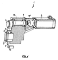
- the cutting system 1 comprises an asynchronous motor 2 which directly, ie without the interposition of a transmission gear, a crankshaft 3 drives (see the partially sectioned view of the cutting system 1 in a perspective view in FIG Fig. 4 ).
- crankshaft 3 is provided at its axial end opposite the asynchronous motor 2 with an eccentric pin 4, to which a connecting rod 5 is articulated, which is articulated at its end facing away from the eccentric pin 4 on a knife holder 6, which in turn is provided with a knife 7 for the execution of Cut is fitted on the wire.
- the knife holder 6 runs in a serving as a bearing guide 8, which in the Fig. 1 and 2 only indicated very schematically and in which it is z. B. act to a carriage guide can. But other suitable possibilities of a bearing or a guide 8 can be considered.
- the guide 8 consists of a frame-fixed fixed bearing element, performs at a rotation of the crankshaft 3 of the knife holder 6 with the knife attached to him 7 a reciprocating, pure translational movement (straight cut).
- the guide 8 is rotatably arranged about a pivot axis 9, as in Fig. 2 is indicated, and connecting rod 5 and knife holder 6 are rigidly connected to each other, in this case leads to a rotation of the crankshaft 3, the knife holder 6 with the knife 7 a superimposed pivotal and translational movement, resulting in a eilipsenförmigen trajectory of the blade 7 (rotating Cut).
- the asynchronous motor 2 drives a flywheel 10 whose kinetic energy is released again when the blade 7 strikes the wire 11 to be cut in the form of the cutting force.
- the wire 11 is severed by the knife 7 in cooperation with a counter cutting tool 12 in the form of a mandrel. If the separation of the wire 11 is carried out, the remaining kinetic energy of the flywheel 10 must be decelerated again, which is done by braking the asynchronous motor 2.
- the cutting energy needed to cut the wire 11 depends on the diameter and tensile strength of the wire 11 to be cut. From this cutting energy and the inertial mass of the entire cutting system 1, the necessary speed to which the flywheel 10 must be accelerated before the cut can be determined.
- flywheel 10 can be z. B. use a separate flywheel. In the embodiment of the Fig. 1, 2 and 4 is used as a flywheel 10 but equal to the crankshaft 3. It would also be possible to use directly the rotor of the induction motor 2 as a flywheel 10. However, the size of the inertia mass 10 used must be so large that the required cutting energy is available with a lying in the speed range of the asynchronous motor 2 speed in the form of kinetic energy available.
- a non-contact encoder system 15 is provided, in which it is quite fundamentally z. B. can be a magnetic incremental encoder or an inductive sensor o. ⁇ .
- a switching cam is used, which defines the zero position of the induction motor 2.
- further switching cam can be provided, for. B. one before immersion of the blade 7 in the wire path and another switching cam after the emergence of the blade 7 from the wire path through which harmonization or optimization of the spring manufacturing cycles is possible without much effort.
- the asynchronous motor 2 is activated by a pulse (energized), wherein after passing through the respectively corresponding switching element, the energization stopped and the cutting system 1 is braked by braking the asynchronous motor 2.
- a pulse energized
- the energization stopped and the cutting system 1 is braked by braking the asynchronous motor 2.
- the asynchronous motor 2 which does not require a high-precision encoder system, it also allows to use simple encoder systems near the (rigid) machine wall, whereby the used sensors are subjected to only lower acceleration forces.
- Fig. 3 shows a diagram of the course of the speed U of the induction motor 2 for a revolution thereof, plotted against the time t.
- the angular positions of the crankshaft 3 at 160 ° and 180 ° and 360 ° corresponding times are given.
- the total duration of this rotation is 320 ms.
- Fig. 3 As can be seen, the cutting system executes exactly one revolution of 360 ° per cutting cycle. During this revolution, only 20% is needed to sever the wire 11. The cut takes place within one revolution of the asynchronous motor 2 at a crankshaft position of 160 ° to 180 ° and does not require any separate transmission. In the range between 0 ° and 180 °, the asynchronous motor is accelerated and then decelerated to 360 °.
Landscapes
- Engineering & Computer Science (AREA)
- Mechanical Engineering (AREA)
- Life Sciences & Earth Sciences (AREA)
- Forests & Forestry (AREA)
- Shearing Machines (AREA)
- Wire Processing (AREA)
Applications Claiming Priority (1)
| Application Number | Priority Date | Filing Date | Title |
|---|---|---|---|
| DE102009022969.8A DE102009022969B4 (de) | 2009-05-28 | 2009-05-28 | Schnittsystem für Drahtbearbeitungsmaschinen |
Publications (2)
| Publication Number | Publication Date |
|---|---|
| EP2255902A2 true EP2255902A2 (fr) | 2010-12-01 |
| EP2255902A3 EP2255902A3 (fr) | 2012-06-06 |
Family
ID=42542880
Family Applications (1)
| Application Number | Title | Priority Date | Filing Date |
|---|---|---|---|
| EP20100002713 Withdrawn EP2255902A3 (fr) | 2009-05-28 | 2010-03-15 | Système de coupe pour machines de travail de fil métallique |
Country Status (3)
| Country | Link |
|---|---|
| US (2) | US20100300254A1 (fr) |
| EP (1) | EP2255902A3 (fr) |
| DE (1) | DE102009022969B4 (fr) |
Cited By (11)
| Publication number | Priority date | Publication date | Assignee | Title |
|---|---|---|---|---|
| CN102284656A (zh) * | 2011-08-19 | 2011-12-21 | 福建水力消防成套设备有限公司 | 一种剪线工具 |
| CN102962510A (zh) * | 2011-08-29 | 2013-03-13 | 张安心 | 多剪速剪板机 |
| CN106040917A (zh) * | 2015-06-05 | 2016-10-26 | 陈仁杰 | 电脑弹簧机刀座驱动机构 |
| CN106077371A (zh) * | 2016-08-11 | 2016-11-09 | 桂林电子科技大学 | 可移动式线缆剪切装置 |
| CN106424900A (zh) * | 2016-11-24 | 2017-02-22 | 无锡市伟丰印刷机械厂 | 一种铝管专用节能型快速切割装置 |
| CN107570635A (zh) * | 2017-08-16 | 2018-01-12 | 建科机械(天津)股份有限公司 | 用于剪切钢筋或钢丝的剪切机构 |
| CN109500311A (zh) * | 2018-12-07 | 2019-03-22 | 韩超 | 一种桥梁施工用钢筋切断机 |
| CN111633432A (zh) * | 2020-06-12 | 2020-09-08 | 杭州丰衡机电有限公司 | 一种机箱数控加工装置 |
| CN112332288A (zh) * | 2020-10-22 | 2021-02-05 | 怀化宇隆电工材料有限公司 | 一种电缆安装用便携电缆截断装置 |
| CN112743435A (zh) * | 2021-01-18 | 2021-05-04 | 上海论车电子科技有限公司 | 一种基于导电性质的可调长度的钢筋切断装置 |
| CN118417442A (zh) * | 2024-07-03 | 2024-08-02 | 常州顺高机械有限公司 | 一种冲压机废料回收设备 |
Families Citing this family (14)
| Publication number | Priority date | Publication date | Assignee | Title |
|---|---|---|---|---|
| US20100269664A1 (en) * | 2009-04-22 | 2010-10-28 | Mike Majchrowski | Servo pouch knife assembly |
| CN103121127A (zh) * | 2011-11-18 | 2013-05-29 | 莱恩精机(深圳)有限公司 | 一种剪切机 |
| DE102013207028B3 (de) * | 2013-04-18 | 2014-06-26 | Wafios Ag | Federwindemaschine mit einstellbarer Schnitteinrichtung |
| CN103341573A (zh) * | 2013-07-05 | 2013-10-09 | 太仓苏晟电气技术科技有限公司 | 一种自动化型材切断装置 |
| CN103480777B (zh) * | 2013-09-04 | 2015-08-19 | 福建省苍乐电子企业有限公司 | 节能灯灯头引脚的加工装置 |
| CN105013978A (zh) * | 2015-08-05 | 2015-11-04 | 河南省四达仙龙实业有限公司 | 一种折弯机的传动机构 |
| CN106180867B (zh) * | 2016-08-09 | 2018-09-21 | 开平力蒲卫浴有限公司 | 一种五金钢管高效率切割装置 |
| CN107755845B (zh) * | 2016-08-22 | 2023-06-30 | 中国石油天然气集团公司 | 一种用于多点焊机的剪丝系统及多点焊机 |
| CN108787948B (zh) * | 2018-06-20 | 2020-04-10 | 佛山市程显科技有限公司 | 一种电子器件引脚剪切装置 |
| CN109910075A (zh) * | 2019-03-29 | 2019-06-21 | 中山市中科智能制造研究院有限公司 | 一种往复式切刀机构 |
| CN111873009A (zh) * | 2020-06-16 | 2020-11-03 | 安徽五优食品有限责任公司 | 一种改进型发糕生产用切割装置 |
| CN111691047A (zh) * | 2020-07-01 | 2020-09-22 | 海宁艾力针织有限公司 | 一种可调节距离的在动绒线切割设备 |
| CN114378874A (zh) * | 2022-02-28 | 2022-04-22 | 安徽汉邦智汇科技有限公司 | 一种大功率调频振动切割装置 |
| DE102023113100A1 (de) * | 2023-05-17 | 2024-11-21 | Wafios Aktiengesellschaft | Mehrteiliges Schnittwerkzeug für Drahtverarbeitungsmaschine |
Citations (4)
| Publication number | Priority date | Publication date | Assignee | Title |
|---|---|---|---|---|
| DE4040659C1 (en) | 1990-12-19 | 1992-02-20 | Wafios Maschinenfabrik Gmbh & Co Kg, 7410 Reutlingen, De | Metal spring coiling machine - incorporates wire feed, coiling tools and cutter |
| DE4138896C2 (fr) | 1990-12-19 | 1993-03-25 | Wafios Maschinenfabrik Gmbh & Co Kg, 7410 Reutlingen, De | |
| EP0798058B1 (fr) | 1996-03-25 | 2000-12-06 | WAFIOS Maschinenfabrik GmbH & Co. Kommanditgesellschaft | Appareil de formage de fil. en particulier machine universelle d'enroulement de ressorts avec dispositif de coupage |
| JP2007069251A (ja) | 2005-09-07 | 2007-03-22 | Asahi-Seiki Mfg Co Ltd | 線材切断装置 |
Family Cites Families (5)
| Publication number | Priority date | Publication date | Assignee | Title |
|---|---|---|---|---|
| US4112721A (en) * | 1976-04-07 | 1978-09-12 | Nhk Spring Co., Ltd. | Nc coil spring manufacturing apparatus |
| US4122721A (en) * | 1977-01-17 | 1978-10-31 | Theodore Zubricki | Water sampling bucket |
| DE3372205D1 (en) * | 1982-07-09 | 1987-07-30 | Emhart Ind | Feeder mechanism for supplying gobs of plastic material |
| US6708591B1 (en) * | 1999-05-03 | 2004-03-23 | Rockford Manufacturing Group, Inc. | Clutchless wire cutting apparatus |
| US6951160B2 (en) * | 2003-07-22 | 2005-10-04 | David Wu | Cutting device for spring manufacturing machines |
-
2009
- 2009-05-28 DE DE102009022969.8A patent/DE102009022969B4/de not_active Expired - Fee Related
-
2010
- 2010-03-15 EP EP20100002713 patent/EP2255902A3/fr not_active Withdrawn
- 2010-05-17 US US12/781,653 patent/US20100300254A1/en not_active Abandoned
-
2014
- 2014-05-12 US US14/275,310 patent/US20140318334A1/en not_active Abandoned
Patent Citations (4)
| Publication number | Priority date | Publication date | Assignee | Title |
|---|---|---|---|---|
| DE4040659C1 (en) | 1990-12-19 | 1992-02-20 | Wafios Maschinenfabrik Gmbh & Co Kg, 7410 Reutlingen, De | Metal spring coiling machine - incorporates wire feed, coiling tools and cutter |
| DE4138896C2 (fr) | 1990-12-19 | 1993-03-25 | Wafios Maschinenfabrik Gmbh & Co Kg, 7410 Reutlingen, De | |
| EP0798058B1 (fr) | 1996-03-25 | 2000-12-06 | WAFIOS Maschinenfabrik GmbH & Co. Kommanditgesellschaft | Appareil de formage de fil. en particulier machine universelle d'enroulement de ressorts avec dispositif de coupage |
| JP2007069251A (ja) | 2005-09-07 | 2007-03-22 | Asahi-Seiki Mfg Co Ltd | 線材切断装置 |
Cited By (14)
| Publication number | Priority date | Publication date | Assignee | Title |
|---|---|---|---|---|
| CN102284656A (zh) * | 2011-08-19 | 2011-12-21 | 福建水力消防成套设备有限公司 | 一种剪线工具 |
| CN102962510A (zh) * | 2011-08-29 | 2013-03-13 | 张安心 | 多剪速剪板机 |
| CN106040917A (zh) * | 2015-06-05 | 2016-10-26 | 陈仁杰 | 电脑弹簧机刀座驱动机构 |
| CN106077371A (zh) * | 2016-08-11 | 2016-11-09 | 桂林电子科技大学 | 可移动式线缆剪切装置 |
| CN106424900B (zh) * | 2016-11-24 | 2018-03-09 | 无锡市伟丰印刷机械厂 | 一种铝管专用节能型快速切割装置 |
| CN106424900A (zh) * | 2016-11-24 | 2017-02-22 | 无锡市伟丰印刷机械厂 | 一种铝管专用节能型快速切割装置 |
| CN107570635A (zh) * | 2017-08-16 | 2018-01-12 | 建科机械(天津)股份有限公司 | 用于剪切钢筋或钢丝的剪切机构 |
| CN107570635B (zh) * | 2017-08-16 | 2023-12-05 | 建科机械(天津)股份有限公司 | 用于剪切钢筋或钢丝的剪切机构 |
| CN109500311A (zh) * | 2018-12-07 | 2019-03-22 | 韩超 | 一种桥梁施工用钢筋切断机 |
| CN111633432A (zh) * | 2020-06-12 | 2020-09-08 | 杭州丰衡机电有限公司 | 一种机箱数控加工装置 |
| CN112332288A (zh) * | 2020-10-22 | 2021-02-05 | 怀化宇隆电工材料有限公司 | 一种电缆安装用便携电缆截断装置 |
| CN112332288B (zh) * | 2020-10-22 | 2021-12-14 | 湖南金缆电工科技有限责任公司 | 一种电缆安装用便携电缆截断装置 |
| CN112743435A (zh) * | 2021-01-18 | 2021-05-04 | 上海论车电子科技有限公司 | 一种基于导电性质的可调长度的钢筋切断装置 |
| CN118417442A (zh) * | 2024-07-03 | 2024-08-02 | 常州顺高机械有限公司 | 一种冲压机废料回收设备 |
Also Published As
| Publication number | Publication date |
|---|---|
| DE102009022969A1 (de) | 2010-12-02 |
| US20100300254A1 (en) | 2010-12-02 |
| US20140318334A1 (en) | 2014-10-30 |
| EP2255902A3 (fr) | 2012-06-06 |
| DE102009022969B4 (de) | 2016-08-04 |
Similar Documents
| Publication | Publication Date | Title |
|---|---|---|
| DE102009022969B4 (de) | Schnittsystem für Drahtbearbeitungsmaschinen | |
| DE102008028652B3 (de) | Pressendirektantrieb | |
| DE10020968B4 (de) | Drahtschneideinrichtung | |
| DE3900734C2 (de) | Vorrichtung zum Richten und Abschneiden von Runddraht oder dergleichen | |
| DE3042897C2 (fr) | ||
| DE102009032231B4 (de) | Presse | |
| EP1759820B1 (fr) | Dispositif pour la découpe de produits sur trois cotés | |
| DE102020103085A1 (de) | Aufschneidevorrichtung mit leerschnittfunktion | |
| DE102012207304A1 (de) | Antriebsvorrichtung | |
| EP2319635B1 (fr) | Entraînement de presse et procédé de production d'un mouvement de levée d'un support d'outils à l'aide d'un entraînement de presses | |
| WO2011023256A1 (fr) | Moteur d'entraînement | |
| EP1344858B1 (fr) | Machine à coudre | |
| EP2764963A2 (fr) | Dispositif destiné à l'ébarbage sur trois côtés de produits | |
| DE3546252A1 (de) | Werkzeugmaschine und deren betriebsverfahren | |
| DE102014106341A1 (de) | Vorrichtung zum Aufschneiden von Lebensmittelprodukten | |
| EP3013494A1 (fr) | Dispositif et procédé de formage de corps cylindriques creux | |
| EP1588813B1 (fr) | Appareil de brochage avec dispositif d' alimentation pour au moins un fil à brocher sans fin | |
| DE817586C (de) | Nagelmaschine | |
| DE959905C (de) | Verfahren und Einrichtung zum Scheren von Textilgeweben | |
| AT270344B (de) | Verfahren und Vorrichtung zum Stanzen von Rotor- und Statorblechen für Elektromotore, vorzugsweise mit konischen Rotoren und Statoren | |
| DE935291C (de) | Maschine zum Herstellen tiefer Ausnehmungen in Werkstuecken, insbesondere tiefer Schlitze in Pleuelstangen | |
| EP2281643A1 (fr) | Dispositif de pliage de pièces tubulaires | |
| DE1165969B (de) | Vorschubeinrichtung fuer mitlaufende Trennmaschinen | |
| DE102006026347B4 (de) | Bürstenherstellungsmaschine | |
| EP2497632B1 (fr) | Unité d'entraînement pour une machine automatique de découpage ou une presse |
Legal Events
| Date | Code | Title | Description |
|---|---|---|---|
| PUAI | Public reference made under article 153(3) epc to a published international application that has entered the european phase |
Free format text: ORIGINAL CODE: 0009012 |
|
| AK | Designated contracting states |
Kind code of ref document: A2 Designated state(s): AT BE BG CH CY CZ DE DK EE ES FI FR GB GR HR HU IE IS IT LI LT LU LV MC MK MT NL NO PL PT RO SE SI SK SM TR |
|
| AX | Request for extension of the european patent |
Extension state: AL BA ME RS |
|
| PUAL | Search report despatched |
Free format text: ORIGINAL CODE: 0009013 |
|
| AK | Designated contracting states |
Kind code of ref document: A3 Designated state(s): AT BE BG CH CY CZ DE DK EE ES FI FR GB GR HR HU IE IS IT LI LT LU LV MC MK MT NL NO PL PT RO SE SI SK SM TR |
|
| AX | Request for extension of the european patent |
Extension state: AL BA ME RS |
|
| RIC1 | Information provided on ipc code assigned before grant |
Ipc: B21F 11/00 20060101ALI20120503BHEP Ipc: B23D 15/02 20060101ALI20120503BHEP Ipc: B21F 3/02 20060101AFI20120503BHEP |
|
| 17P | Request for examination filed |
Effective date: 20121010 |
|
| 17Q | First examination report despatched |
Effective date: 20171018 |
|
| STAA | Information on the status of an ep patent application or granted ep patent |
Free format text: STATUS: THE APPLICATION IS DEEMED TO BE WITHDRAWN |
|
| 18D | Application deemed to be withdrawn |
Effective date: 20190528 |