EP2255293B1 - Apparatuses and methods for evaluating a person for a sleep system - Google Patents
Apparatuses and methods for evaluating a person for a sleep system Download PDFInfo
- Publication number
- EP2255293B1 EP2255293B1 EP08872303A EP08872303A EP2255293B1 EP 2255293 B1 EP2255293 B1 EP 2255293B1 EP 08872303 A EP08872303 A EP 08872303A EP 08872303 A EP08872303 A EP 08872303A EP 2255293 B1 EP2255293 B1 EP 2255293B1
- Authority
- EP
- European Patent Office
- Prior art keywords
- person
- support
- comfort
- layer
- pressure
- Prior art date
- Legal status (The legal status is an assumption and is not a legal conclusion. Google has not performed a legal analysis and makes no representation as to the accuracy of the status listed.)
- Active
Links
- 238000000034 method Methods 0.000 title claims description 37
- 238000012360 testing method Methods 0.000 description 67
- 238000005259 measurement Methods 0.000 description 48
- 238000003384 imaging method Methods 0.000 description 8
- 238000004458 analytical method Methods 0.000 description 6
- 230000000694 effects Effects 0.000 description 6
- 239000000463 material Substances 0.000 description 6
- 238000011156 evaluation Methods 0.000 description 5
- 238000009826 distribution Methods 0.000 description 4
- 239000006260 foam Substances 0.000 description 3
- 230000037396 body weight Effects 0.000 description 2
- 239000006185 dispersion Substances 0.000 description 2
- 239000012530 fluid Substances 0.000 description 2
- 239000004033 plastic Substances 0.000 description 2
- 229920003023 plastic Polymers 0.000 description 2
- 239000004793 Polystyrene Substances 0.000 description 1
- 238000004026 adhesive bonding Methods 0.000 description 1
- 230000036772 blood pressure Effects 0.000 description 1
- -1 but not limited to Substances 0.000 description 1
- 210000000085 cashmere Anatomy 0.000 description 1
- 238000013461 design Methods 0.000 description 1
- 238000010586 diagram Methods 0.000 description 1
- 229920001971 elastomer Polymers 0.000 description 1
- 239000002657 fibrous material Substances 0.000 description 1
- 239000004619 high density foam Substances 0.000 description 1
- 230000007774 longterm Effects 0.000 description 1
- 239000004620 low density foam Substances 0.000 description 1
- 239000004745 nonwoven fabric Substances 0.000 description 1
- 238000010606 normalization Methods 0.000 description 1
- 238000000053 physical method Methods 0.000 description 1
- 229920001084 poly(chloroprene) Polymers 0.000 description 1
- 229920002223 polystyrene Polymers 0.000 description 1
- 230000001144 postural effect Effects 0.000 description 1
- 230000029058 respiratory gaseous exchange Effects 0.000 description 1
- 230000004044 response Effects 0.000 description 1
- 238000009958 sewing Methods 0.000 description 1
- 239000007779 soft material Substances 0.000 description 1
- 238000007619 statistical method Methods 0.000 description 1
- 125000000391 vinyl group Chemical group [H]C([*])=C([H])[H] 0.000 description 1
- 229920002554 vinyl polymer Polymers 0.000 description 1
- 210000002268 wool Anatomy 0.000 description 1
Images


Classifications
-
- A—HUMAN NECESSITIES
- A61—MEDICAL OR VETERINARY SCIENCE; HYGIENE
- A61B—DIAGNOSIS; SURGERY; IDENTIFICATION
- A61B5/00—Measuring for diagnostic purposes; Identification of persons
- A61B5/48—Other medical applications
- A61B5/4806—Sleep evaluation
-
- A—HUMAN NECESSITIES
- A47—FURNITURE; DOMESTIC ARTICLES OR APPLIANCES; COFFEE MILLS; SPICE MILLS; SUCTION CLEANERS IN GENERAL
- A47C—CHAIRS; SOFAS; BEDS
- A47C31/00—Details or accessories for chairs, beds, or the like, not provided for in other groups of this subclass, e.g. upholstery fasteners, mattress protectors, stretching devices for mattress nets
- A47C31/12—Means, e.g. measuring means for adapting chairs, beds or mattresses to the shape or weight of persons
- A47C31/123—Means, e.g. measuring means for adapting chairs, beds or mattresses to the shape or weight of persons for beds or mattresses
-
- G—PHYSICS
- G16—INFORMATION AND COMMUNICATION TECHNOLOGY [ICT] SPECIALLY ADAPTED FOR SPECIFIC APPLICATION FIELDS
- G16Z—INFORMATION AND COMMUNICATION TECHNOLOGY [ICT] SPECIALLY ADAPTED FOR SPECIFIC APPLICATION FIELDS, NOT OTHERWISE PROVIDED FOR
- G16Z99/00—Subject matter not provided for in other main groups of this subclass
-
- A—HUMAN NECESSITIES
- A61—MEDICAL OR VETERINARY SCIENCE; HYGIENE
- A61B—DIAGNOSIS; SURGERY; IDENTIFICATION
- A61B2562/00—Details of sensors; Constructional details of sensor housings or probes; Accessories for sensors
- A61B2562/02—Details of sensors specially adapted for in-vivo measurements
- A61B2562/0247—Pressure sensors
Definitions
- Methods and apparatuses consistent with the present invention relate generally to the evaluation of a person that is positioned on a sleep system. More particularly, these methods and apparatuses relate to the measurement and analysis of characteristics of a particular person for a sleep system, to determining the sleep system characteristics that are most suitable for the person, and to providing a recommendation for a sleep system that is most suitable for the person.
- sleep systems may comprise all aspects of a bedding assembly including, but not limited to, mattresses, box springs, foundation units, bed frames, pillows, mattress pads, linens and, more generally, to any type of sleep product that influences a person's sleep.
- each respective sleep system may be suitable for some persons but not suitable for others persons.
- the characteristics of a suitable sleep system for a person depend on a number of factors including, but not limited to, the physical attributes of the person (e.g., weight, height, body dimensions, weight distribution, etc.), preferred sleeping positions (e.g., sleeping on back, side, front, etc.), sleeping habits and so on.
- a sleep system delivers support to a person by holding the person in a proper postural alignment, while evenly redistributing the person's body weight across a wide area so as to relieve interface pressure.
- a mattress may deliver support through the resistance provided by innersprings to the downward force applied due to the person's body weight.
- a sleep system delivers comfort to a person's body through the use of comfort materials layered on a top region of the sleep surface. For instance, by layering firming pads and harder, high density foam on top of the innersprings, a mattress can be manufactured to provide varying levels of hardness or firmness. On the other hand, by layering soft materials over the innersprings like convoluted foam, low density foam and/or fiber materials like wool, silk or cashmere, a mattress can be manufactured to provide varying levels of softness or a more plush feel.
- the sleep system that is most suitable for a particular person is that sleep system which provides the best possible combination of comfort and support to the person. Further, suitable sleep systems will vary considerably based on a person's physical attributes, sleeping habits, etc.
- the number of factors that influence the suitability of a sleep system for a person are vast and interrelated.
- the selection of a suitable sleep system can be a complicated and difficult process for a person.
- the sleep system that a person selects for themselves based on what sleep system feels most appealing to the person during a showroom testing of the sleep system may not be the most suitable sleep system for the person. Rather, it may require several weeks of sleeping on a given sleep system for a person to determine the long-term suitability of the sleep system.
- prospective sleep system purchasers are generally limited to such brief showroom testing.
- Methods and apparatuses consistent with the present invention relate to the evaluation of a person for a sleep system, the measurement and analysis of physical characteristics of a person on a sleep system, the determination of sleep system characteristics that are most suitable for the person, and the recommendation of a sleep system that is most suitable for the person. Methods and apparatuses consistent with the present invention also relate to measuring and analyzing the effect of a person on a mattress and a foundation and to providing a recommendation for a suitable sleep system using such an analysis.
- a method for evaluating a person for a sleep system comprising: while the person is not positioned on an evaluating member, adjusting a pressure of a comfort layer inflatable member disposed within a comfort layer of the evaluating member to an initial comfort value; positioning the person on the evaluating member in a first position; while the person is positioned on the evaluating member in the first position, measuring a pressure of the comfort layer inflatable member as a first measured comfort value; calculating a difference between the first measured comfort value and the initial comfort value as ⁇ COMFORT PRESSURE 1 ; calculating a first optimal pressure level for the comfort layer inflatable member using ⁇ COMFORT PRESSURE 1 ; and recommending a sleep support member for the person using the calculated first optimal pressure level for the comfort layer inflatable member and using data measuring quality of sleep, and adjusting the comfort layer inflatable member to the calculated first optimal pressure level for the comfort layer inflatable member.
- a method for evaluating a person for a sleep system comprising: while the person is not positioned on an evaluating member: adjusting a pressure of a comfort layer inflatable member disposed within a comfort layer of the evaluating member to a initial comfort value; and adjusting a pressure of a support layer inflatable member disposed within a support layer of the evaluating member to an initial support value; positioning the person on the evaluating member in a first position; while the person is positioned on the evaluating member in the first position: measuring a pressure of the comfort layer inflatable member as a first measured comfort value; and measuring a pressure of the support layer inflatable member as a first measured support value; calculating a difference between the first measured comfort value and the initial comfort value as ⁇ COMFORT PRESSURE 1 ; calculating a difference between the first measured support value and the initial support value as ⁇ SUPPORT PRESSURE 1 ; calculating a first optimal pressure level for the comfort layer inflatable member using ⁇ COMFORT PRESS
- FIG. 1 illustrates a cross-sectional view of an apparatus for evaluating a person for a sleep system according to an illustrative embodiment of the present invention
- FIG. 2 illustrates a perspective view of an apparatus for evaluating a person for a sleep system according to an illustrative embodiment of the present invention
- FIG. 3 illustrates a schematic diagram of a sense and control unit according to an illustrative embodiment of the present invention
- FIG. 4 illustrates a flow chart for a method of evaluating a person for a sleep system according to an illustrative embodiment of the present invention
- FIG. 5 illustrates a second flow chart for a method of evaluating a person for a sleep system according to an illustrative embodiment of the present invention
- FIG. 6 illustrates a view of an inflatable member according to an illustrative embodiment of the present invention
- FIG. 7A illustrates a cross-sectional view of an apparatus for evaluating a person for a sleep system comprising a third force dispersing cover according to an illustrative embodiment of the present invention
- FIG. 7B illustrates a cross-sectional view of an apparatus for evaluating a person for a sleep system having a third force dispersing cover according to an illustrative embodiment of the present invention
- FIG. 8 illustrates a cross-sectional view of an apparatus for evaluating a person for a sleep system wherein a group S1 of support layer inflatable members are inflated according to an illustrative embodiment of the present invention
- FIG. 9A illustrates a side view of one end of an inflatable member according to an illustrative embodiment of the present invention.
- FIG. 9B illustrates a top view of an inflatable member according to an illustrative embodiment of the present invention.
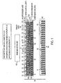
- FIG. 1 illustrates a cross-sectional view of an apparatus for evaluating a person for a sleep system consistent with an illustrative embodiment of the present invention.
- a test bed 101 for evaluating a person for a sleep system comprises a mattress layer 102 and a foundation layer 103, which is disposed below the mattress layer 102.
- the test bed 101 is an apparatus designed to simulate various components of a sleep system and to evaluate the characteristics of a person positioned on the test bed 101.
- the test bed 101 is connected to a sense and control unit 150.
- the test bed 101 may be employed in a bedding store showroom to assist purchasers in the selection of sleep system components such as a mattress, a box spring unit, or a pillow.
- the test bed 101 may also be employed to assist salespersons in providing recommendations to purchasers regarding the suitability of particular sleep system components currently in stock.
- the test bed 101 may be employed to measure and analyze the particular characteristics of a person so that a customized sleep system may be designed and manufactured for the person.
- the foundation layer 103 is configured to simulate a box spring of a sleep system.
- the foundation layer 103 comprises a plurality of foundation coils 104.
- the layer of foundation coils 104 is arranged in rows of coils that extend in a longitudinal direction of the test bed 101 (i.e., the rows of coils extend from the head of the test bed 101 to the foot of the test bed 101).
- the present invention is not limited to this illustrative configuration of coils and the rows of coils comprising the layer of foundation coils 104 may extend laterally across the width of the test bed 101 consistent with the present invention. More generally, the rows of coils comprising the layer of foundation coils 104 may comprise any arrangement of coils and the present invention is not limited to any specific configuration of coils.
- the foundation layer 103 further comprises a plurality of foundation sensors 105, which are configured to measure the amount of pressure applied to the foundation sensors 105.
- each of the foundation sensors 105 is configured to provide real time measurements relating to the amount of pressure applied by the mattress layer 102 to various positions on the foundation layer 103. Such pressure may be applied, for example, as a result of a person positioned on the mattress layer 102.
- the foundation layer 103 comprises eight foundation sensors 105, but the present invention is not limited to this configuration and a larger or smaller number of foundation sensors 105 may be employed consistent with the present invention.
- the plurality of foundation sensors 105 are grouped into two groups, F1 and F2, but the present invention is not limited to this configuration and a wide variety of groupings of the foundation sensors 105 may be employed, or the foundation sensors 105 need not be grouped at all. Consistent with the present invention, measurements obtained by the foundation sensors 105 allow for, among other things, evaluation of a person that is positioned on the test bed 101.
- the foundation sensors 105 allow an evaluation of the pressure applied to the foundation layer 103. Measurements obtained by the foundation sensors 105 also allow for the identification of the foundation or box spring unit that is most suitable for the person.
- the mattress layer 102 is configured to simulate a typical mattress of a sleep system. As shown in FIG. 1 , the mattress layer 102 comprises a comfort measurement/adjustment layer 120 and a support measurement/adjustment layer 130 that is disposed below the comfort measurement/adjustment layer 120.
- the comfort measurement/adjustment layer 120 and the support measurement/adjustment layer 130 are configured to allow measurement and adjustment of (among a wide variety of other measurements) the two primary components of sleep systems mentioned above that affect a person's overall sleep experience, namely, comfort and support.
- the comfort measurement/adjustment layer 120 is configured to measure and adjust the pressure applied to a top region of the test bed 101 at various regions of the person's body while a person is positioned on the test bed 101. More particularly, the comfort measurement/adjustment layer 120 is configured to allow immediate measurements and adjustments to the region of a sleep system that typically delivers comfort to a person's body through the use of comfort layers at a top region of the sleep surface. The comfort measurement/adjustment layer 120 is configured to simulate varying types of such comfort layers.
- the support measurement/adjustment layer 130 is configured to measure and adjust the pressure applied to a region of the test bed 101 below the comfort measurement/adjustment layer 120 at various regions of the person's body while a person is positioned on the test bed 101. More particularly, the support measurement/adjustment layer 130 is configured to allow immediate measurements and adjustments to the region of a sleep system that typically delivers support to a person's body through the resistance provided by the innersprings. The support measurement/adjustment layer 130 is configured to simulate varying levels of support that can be provided by a sleep system.
- the support measurement/adjustment layer 130 comprises a layer of mattress upper coils 131 and a layer of mattress lower coils 132.
- the layer of mattress upper coils 131 and the layer of mattress lower coils 132 are arranged in rows of coils that extend in a longitudinal direction of the test bed 101 (i.e., the rows of coils extend from the head of the test bed 101 to the foot of the test bed 101).
- the present invention is not limited to this illustrative configuration of coils and the rows of coils comprising the layer of mattress upper coils 131 and the layer of mattress lower coils 132 may extend laterally across the width of the test bed 101 consistent with the present invention. More generally, the rows of coils comprising the layer of mattress upper coils 131 and the layer of mattress lower coils 132 may comprise any arrangement of coils and the present invention is not limited to any specific configuration of coils.
- the coils comprising the layer of mattress upper coils 131 and the layer of mattress lower coils 132 comprise what is known in the industry as pocketed coil springs in which each spring is individually enclosed within a pocket of material.
- the present invention is not limited to a configuration employing pocketed coils and a wide variety of support devices can be used consistent with the present invention, including, but not limited to, layers of plastic based materials or other engineered support systems.
- the coils comprising the layer of mattress upper coils 131 are formed of a higher gauge material than the coils comprising the layer of mattress lower coils 132.
- the coils comprising the layer of mattress upper coils 131 may be formed of 16 gauge wire (i.e., softer coils), whereas the coils comprising the layer of mattress lower coils 132 may be formed of 14 gauge wire (i.e., firmer coils).
- the coils comprising the layer of mattress upper coils 131 compress more easily than the coils comprising the layer of mattress lower coils 132.
- a plurality of support layer inflatable members or bladders 134 are disposed between the layer of mattress upper coils 131 and the layer of mattress lower coils 132. As shown in FIG. 1 , there are three groups of support layer inflatable members 134, which are respectively referenced as S1, S2 and S3. However, the present invention is not limited to the configuration shown in FIG. 1 and any number of groups of support layer inflatable members 134 may be employed. According to the illustrative embodiment shown in FIG. 1 , the support layer inflatable members 134 are pneumatic and are connected to a pump/vacuum unit 310 (shown in FIG. 3 ) via pneumatic tubes.
- the present invention is not limited to this illustrative configuration and other gasses or fluids besides air may be used to inflate / deflate the support layer inflatable members 134 to a desired pressure.
- the support layer inflatable members 134 may be constructed of a variety of materials including, but not limited to plastic, vinyl, neoprene, rubber and the like. According to the illustrative embodiment shown in FIG. 1 , the support layer inflatable members 134 extend in a lateral direction across the width of the test bed 101.
- the support layer inflatable members 134 are configured such that, when inflated, the support layer inflatable members 134 apply forces to the layer of mattress upper coils 131 and to the layer of mattress lower coils 132.
- FIG. 1 illustrates a cross-sectional view of the test bed 101 wherein a group S1 of support layer inflatable members 134 are deflated.
- FIG. 8 illustrates a cross-sectional view of the test bed 101 wherein the group of inflatable members S1 is inflated.
- the support characteristics of the test bed 101 can be adjusted. For example, if it is desired to provide more support for the person's lower back region, then the support layer inflatable members 134 disposed under the person's lower back region can be controlled to further inflate. Consequently, the support layer inflatable members 134 apply greater forces to the coils within the layer of mattress upper coils 131 and the layer of mattress lower coils 132 that are disposed under the person's lower back region, causing the aforementioned coils to further compress and, in turn, apply greater support to the person's lower back region.
- the test bed 101 is connected to a sense and control unit 150.
- a detailed illustration of the sense and control unit 150 is shown in FIG. 3 .
- the sense and control unit 150 comprises a plurality of comfort layer sensors 128, which are respectively associated with the comfort layer inflatable members 124, which are respectively referenced as C1, C2, C3, C4, C5, C6, C7, C8, C9, C10, C11, C12, C13, C14 and C15.
- the sense and control unit 150 further comprises a plurality of support layer sensors 138, which are respectively associated with the groups S1, S2 and S3 of support layer inflatable members 134.
- the sense and control unit 150 also comprises a plurality of foundation layer sensors 105, which are respectively referenced as F1 and F2.
- the sense and control unit 150 comprises an embedded control unit 300, a pump/vacuum unit 310 and an auxiliary exhaust unit 320.
- the embedded control unit further comprises a processor 330.
- the pump/vacuum unit 310 may be controlled by the embedded control unit 300 to pump or suck air as desired to/from the support layer inflatable members 134 and the comfort layer inflatable members 124.
- the auxiliary exhaust unit 320 actively or passively exhausts gas or fluid from the support layer inflatable members 134 and the comfort layer inflatable members 124.
- each of the plurality of support layer sensors 138 are connected to a respective group of the support layer inflatable members 134.
- a group of five support layer inflatable members 134 on the left region of the test bed 101, as shown in FIG. 1 is connected to the support layer sensor S1, as shown in FIGS. 1 and 3 .
- a group of five support layer inflatable members 134 in the center region of the test bed 101, as shown in FIG. 1 is connected to the support layer sensor S2.
- a group of five support layer inflatable members 134 on the right side of the test bed 101, as shown in FIG. 1 is connected to the support layer sensor S3.
- the present invention is not limited to the specific configuration shown in FIGS. 1 and 3 and a wide variety of groupings of the support layer sensors 138 may be used consistent with the present invention.
- each of the plurality of support layer sensors 138 can be connected to a respective one of the support layer inflatable members 134.
- Each of the support layer sensors 138 is configured to provide real time measurements relating to the pressure of a respective support layer inflatable member 134 or a respective group of support layer inflatable members 134. As such, when a person is positioned on the test bed 101 measurements relating to the pressure of respective support layer inflatable members 134 can be acquired and analyzed. Using such measurements, a support layer pressure profile of the person can be obtained and used to determine the most suitable sleep system support layer characteristics for the person.
- the support measurement/adjustment layer 130 comprises fifteen support layer inflatable members 134, but the present invention is not limited to this configuration and a larger or smaller number of support layer inflatable members 134 may be employed consistent with the present invention.
- each support layer inflatable member 134 is configured to apply forces to a plurality of rows of mattress upper coils 131 and to a plurality of rows of mattress lower coils 132. That is, each support layer inflatable member 134 is aligned with more than one row of coils.
- each support layer inflatable member 134 can be positioned without regard to the position of the individual coils of the layer of mattress upper coils 131 and the layer of mattress lower coils 132.
- the support layer inflatable members 134 may be attached to the coils of the layer of mattress upper coils 131 and to the layer of mattress lower coils 132, for example, by gluing each support layer inflatable member 134 to the coils.
- a first force dispersing cover 135 may be disposed between the support layer inflatable members 134 and the coils of the layer of mattress upper coils 131.
- the first force dispersing cover 135 facilitates the dispersion of the force applied by each support layer inflatable member 134 among a plurality of rows of mattress upper coils 131.
- the first force dispersing cover 135 may be comprised of a wide variety of materials including, but not limited to, non-woven fabric, polystyrene, etc.
- a second force dispersing cover 136 may be disposed between the support layer inflatable members 134 and the layer of mattress lower coils 132.
- the second force dispersing cover 136 facilitates the dispersion of the force applied by each support layer inflatable member 134 among a plurality of rows of mattress lower coils 132.
- the first force dispersing cover 135 may be glued to the coils of the layer of mattress upper coils 131 and the second force dispersing cover 136 may be glued to the layer of mattress lower coils 132.
- the first and second force dispersing covers 135 and 136 may be glued to the coils of the layer of mattress upper coils 131 and the second force dispersing cover 136 may be glued to the layer of mattress lower coils 132.
- FIG. 1 also shows an illustrative embodiment wherein the layer of mattress upper coils 131, the layer of mattress lower coils 132 and the support layer inflatable members 134 are enclosed by a foam encasement 180.
- an upper buildup layer 190 is disposed above the layer of mattress upper coils 131.
- the upper buildup layer 190 comprises a plurality of comfort layer inflatable members 124 that are disposed above the layer of mattress upper coils 131 and below a topmost layer 195.
- the configuration of each of the respective comfort layer inflatable members 124 is similar to the configuration of the support layer inflatable members 134, discussed above.
- the comfort layer inflatable members 124 are configured such that, when inflated, the comfort layer inflatable members 124 apply forces to the layer of mattress upper coils 131, to the upper buildup layer 190 and to the topmost layer 195. Accordingly, by controlling the inflation / deflation of the comfort layer inflatable members 124 the comfort characteristics of the test bed 101 can be adjusted. For instance, the inflation / deflation of the comfort layer inflatable members 124 can be controlled to change the comfort level of the test bed 101 by making the comfort measurement/adjustment layer 120 either firmer or softer. That is, inflating or deflating a respective one of the comfort layer inflatable members 124 has the effect of compressing or decompressing upper buildup layer 190 and thereby creating a different interface profile (or feel) for the occupant of the test bed 101.
- the sense and control unit 150 determines to make the comfort measurement/adjustment layer 120 firmer under the shoulder region of the person, then the respective comfort layer inflatable member(s) 124 under the person's shoulder region is/are further inflated.
- the sense and control unit 150 determines to make the comfort measurement/adjustment layer 120 softer under the shoulder region of the person, then the respective comfort layer inflatable member(s) 124 under the person's shoulder region is/are further deflated so as to have more cushion in those areas.
- each of a plurality of comfort layer sensors 128 are connected to a respective one of the comfort layer inflatable members 124.
- Each of the comfort layer sensors 128 is configured to provide real time measurements relating to the pressure of a respective comfort layer inflatable member 124.
- the fifteen comfort layer inflatable members 124 are connected to fifteen comfort layer sensors 128.
- the present invention is not limited to this configuration and a larger or smaller number of comfort layer sensors 128 may be employed consistent with the present invention.
- each of the comfort layer inflatable members 124 is aligned with a respective one of the support layer inflatable members 134, however, such alignment is not necessary and illustrative embodiments of the invention my comprise configurations of comfort layer inflatable members 124 and support layer inflatable members 134 that are not aligned.
- the comfort layer inflatable members 124 need not be aligned with a respective row of the mattress upper coils 131. Indeed, a respective comfort layer inflatable member 124 may be aligned with more than one of the rows of mattress upper coils 131. Alternatively, the comfort layer inflatable members 124 can be positioned without regard to the position of the individual mattress upper coils 131.
- measurements relating to the pressure of respective comfort layer inflatable members 124 can be acquired and analyzed. Using such measurements, a comfort layer pressure profile of the person can be obtained and used to determine the most suitable sleep system comfort layer characteristics for the person.
- the support layer sensors 138 and the comfort layer sensors 128 provide the ability to measure a wide variety of data. For example, when a person is positioned on the test bed 101, data provided by the support layer sensors 138 and the comfort layer sensors 128 can be analyzed to determine, among other things, the person's weight, weight distribution, breathing rate, heart rate, state of sleep, etc.
- the illustrative embodiment shown in FIG. 1 comprises a foundation layer 103, a comfort measurement/adjustment layer 120 and a support measurement/adjustment layer 130
- the present invention is not limited to this configuration.
- illustrative embodiments of the present invention may include only the foundation layer 103, or only the comfort measurement/adjustment layer 120, or only the support measurement/adjustment layer 130, or may include any combination of the aforementioned layers.
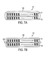
- the test bed 101 may comprise a third force dispersing cover 600, which is wrapped around the layer of mattress upper coils 131 and the layer of mattress lower coils 132.
- the third force dispersing cover 600 extends the length of the test bed 101, but does not extend over the head or the foot of the test bed 101.
- the third force dispersing cover 600 is, for illustrative purposes, shown as loosely surrounding the layer of upper coils 131 and the layer of lower coils 132.
- illustrative embodiments of the present invention may comprise a third force dispersing cover 600 that is tightly wrapped around the layer of upper coils 131 and the layer of lower coils 132.
- the third force dispersing cover 600 disperses the forces applied by the mattress upper coils 131 and the layer of mattress lower coils 132 over a greater area of the foam encasement layer 180 (shown in FIG. 1 ) and, thus, helps to prevent a crowning effect that may occur at the top surface of the test bed 101.
- the third force dispersing cover 600 is attached to a bottom border of the test bed 101 (e.g., border wire) and does not extend below the layer of lower coils 132.
- the third force dispersing cover 600 extends below the layer of lower coils 132. Further, as shown in FIG. 7B , two opposing portions of the third force dispersing cover 600 are attached together at attachment portion 604. For example, the two opposing portions of the third force dispersing cover 600 may be attached via an ultrasonic weld, sewing, staples, etc.
- the present invention is not limited to the two exemplary configurations shown in FIGS. 7A and 7B and the third force dispersing cover 600 may assume a wide variety of configurations.
- FIG. 2 shows a perspective view of an apparatus for evaluating a person for a sleep system according to an illustrative embodiment of the present invention.
- the support layer inflatable members 134, the support layer sensors 138, the comfort layer inflatable members 124, and the comfort layer sensors 128 are all connected to a sense and control unit 150.
- a display 250 is connected to the sense and control unit 150 and a database 200 is connected to the sense and control unit 150.
- a digital imaging device 260 is positioned near the test bed 101 so as to acquire a digital image of a person positioned on the test bed 101.
- the digital imaging device 260 is connected to the sense and control unit 150.
- the digital imaging device 260 is configured to acquire a digital image of a person positioned on the test bed 101.
- the sense and control unit 150 then controls the processor 330 to process the acquired digital image.
- a digital imaging device 260 to acquire a digital image of a person positioned on the test bed 101
- the present invention is not limited to this configuration. Indeed, any other device capable of measuring physical attributes of the person positioned on the test bed 101 may be used consistent with the present invention.
- measurements regarding the physical attributes of the user can also be obtained by embedding additional sensors in the test bed 101 or by eliciting responses from the person to questions relating to their physical attributes.
- illustrative embodiments of the present invention may employ scientific or statistical analysis techniques in place of the digital imaging device 260.
- FIG. 4 shows a flow chart for a method of evaluating a person for a sleep system according to an illustrative embodiment of the present invention.
- the sense and control unit 150 first initiates a calibration mode by inflating /deflating each of the respective support layer inflatable members 134 and comfort layer inflatable members 124 until the pressures of each of the inflatable members 134 and 124 are set to a predetermined state.
- a person lies down on the test bed 101 and the person positions themselves in a particular position.
- the person can position themselves on the test bed 101 lying on their back in a supine position, on their front, on their side or, more generally, any possible position.
- the sense and control unit 150 acquires measurement data from each of the foundation sensors 105, the support layer sensors 138, and the comfort layer sensors 128. Then, the processor 330 calculates a change in pressure ( ⁇ Pressure ) for each of the respective foundation sensors 105, support layer sensors 138, and comfort layer sensors 128. By applying various algorithms to the calculated change in pressure ( ⁇ Pressure ), the processor 330 can determine a variety of useful analytical measurements of the person.
- the general body dimensions and weight distribution (among other things) of a person disposed on the test bed 101 can be statistically predicted.
- the processor 330 can use these statistically predicted values to determine the best combinations of zoned support and zoned comfort provided by the test bed 101 that is needed to produce a healthy sleep system. More generally, the processor 330 can analyze the overall effect of the person's body on various points on the mattress layer 102 and the foundation layer 103 using the measurement data acquired from each of the foundation sensors 105, the support layer sensors 138, and the comfort layer sensors 128.
- the digital imaging device 260 acquires a digital image of the person as the person is positioned on the test bed 101.
- the acquired digital image is then processed by the processor 330 and, using various analytical algorithms, a variety of the person's physical attributes can be determined.
- the processor 330 can determine the height of the person, the width of the person's shoulders, waist, hip and head, the distance from the person's head to shoulders, and the person's position on the test bed 101.
- all of the support layer inflatable members 134 and comfort layer inflatable members 124 are hyper-inflated while the person remains in a stable position on the test bed 101.
- This hyper-inflation causes the test bed 101 to "fill-in” or help learn the person's body while also preparing for the normalization process (discussed in detail below).
- Hyper inflation is basically a maximum pressure that may be varied depending on initial readings (much like a blood pressure device).
- the optimal pressure levels for each of the respective support layer inflatable members 134 and comfort layer inflatable members 124 at which the test bed 101 provides optimal comfort and support characteristics to the person are calculated using the ⁇ Pressure and the acquired digital image.
- illustrative embodiments of the present invention may also calculate the optimal pressure levels for each of the respective support layer inflatable members 134 and comfort layer inflatable members 124 without using the acquired digital image. For instance, other means of physical measurement may be used or the optimal pressure levels can be calculated using the ⁇ Pressure alone.
- Optimal comfort and support characteristics for respective persons can be determined, for example, by analyzing data obtained by observing a plurality of different persons of varying physical attributes (e.g., persons of different heights, weights, weight distributions, waist widths, shoulder widths, etc.) as they are positioned on a variety of different sleep systems, in a variety of different sleeping positions and by recording observed data in the database 200.
- a correspondence between particular physical attributes of persons and suitable sleep systems can be established and stored in the database 200.
- test beds acquire pressure reading data for a plurality of zones and such data are processed to recommend one of a plurality of mattresses based on the closest fit of the data.
- a system allows a retail mattress store to collect data from a sensor pad positioned on top of a support surface to generate a pressure profile for that person. The pressure profile and other information are used to generate specific mattress design parameters or coefficients which are then utilized in designing a specific mattress uniquely customized for that person.
- the '192 patent, the '950 patent, the '425 patent and the '328 patent are merely examples of analysis systems and the present invention is not limited to these examples.
- the optimal comfort and support characteristics for respective persons can be determined using anthropometric data.
- anthropometric data are provided by the publications " Humanscale 1/2/3" by Niels Diffrient et al., MIT Press, copyright 1974 , " Humanscale 4/5/6” by Niels Diffrient et al., MIT Press, copyright 1981 , " The Measure of Man & Women,” Revised Edition, Alvin R. Tilley, John Wiley & Sons, Inc., copyright 2002 .
- the processor 330 adjusts and normalizes each of the support layer inflatable members 134 and comfort layer inflatable members 124 to the calculated optimal pressure levels so that the test bed 101 provides optimal comfort and support characteristics to the person.
- the sense and control unit 150 causes recommendations to be provided to the person via the display 250 regarding suitable sleep system products that provide the optimal comfort and support characteristics that were calculated in operation S406.
- suitable sleep system products that provide the optimal comfort and support characteristics that were calculated in operation S406.
- recommendations can be provided regarding the pillow size and pillow type that is most suitable for the person.
- recommendations can be provided regarding the most suitable variable support and variable comfort settings to which a variable support / variable comfort sleep system can be adjusted.
- a variable support / variable comfort sleep system has been developed by the inventors of the present application, as set forth in a related U. S. Provisional Application No. 61/028,591 entitled, "Apparatuses and Methods Providing Variable Support and Variable Comfort Control of a Sleep System and Automatic Adjustment Thereof.”
- Recommendations can also be provided regarding a customized non-adjustable mattress than can be custom manufactured for the person.
- recommendations can be provided regarding which type of conventional mattresses currently in the showroom will provide the most suitable support and comfort characteristics to the person.
- FIG. 5 illustrates a second flow chart for a method of evaluating a person for a sleep system according to an illustrative embodiment of the present invention.
- the operations S501, S502, S503, S504, S505, S506, S507 and S508 are analogous to operations S401, S402, S403, S404, S405, S406, S407 and S408 discussed above with reference to FIG. 4 .
- the flow chart illustrated in FIG. 5 differs from FIG.
- operation S516 is performed.
- operation S510 is performed, wherein the person moves to a preferred sleeping position. For example, if the person typically prefers to sleep on their side, then the person moves to a position on their side. On the other hand, if the person typically prefers to sleep on their front, for instance, then the person moves to a position on their front in a prone position.
- the sense and control unit 150 initiates a reset calibration mode by inflating / deflating each of the respective support layer inflatable members 134 and comfort layer inflatable members 124 until the pressures of each of the inflatable members 134 and 124 are set to a predetermined state.
- the sense and control unit 150 acquires measurement data from each of the foundation sensors 105, the support layer sensors 138, and the comfort layer sensors 128.
- the processor 330 again analyzes the overall effect of the person's body on various points on the mattress layer 102 and the foundation layer 103.
- the processor 330 adjusts and normalizes each of the support layer inflatable members 134 and comfort layer inflatable members 124 to the calculated optimal pressure levels so that the test bed 101 provides optimal comfort and support characteristics to the person, while the person is positioned in their preferred sleeping position.
- operation S517 is performed, wherein the support layer inflatable members 134 and comfort layer inflatable members 124, located in regions corresponding to the neck and upper back region of the person, are hyper-inflated while the person remains in a stable position on the test bed 101.
- the processor 330 adjusts and normalizes each of the support layer inflatable members 134 and comfort layer inflatable members 124, located in areas corresponding to the neck and upper back region of the person, to the calculated optimal pressure levels so that the test bed 101 provides optimal comfort and support characteristics to the person in areas corresponding to the neck and upper back region of the person.
- operation S508 is performed and recommendations are provided to the person via the display 250 regarding suitable sleep system products that provide the optimal comfort and support characteristics that were calculated by the processor 330 in operation S506, in operation S514, and in operation S518.
- the present invention can also be employed to evaluate multiple persons for a sleep system.
- apparatuses and methods consistent with the present invention may be used to evaluate a person and a sleeping partner on a sleep system.
- the test bed 101 may comprise two separate testing surfaces so that one or two persons can be evaluated at the same time.
- apparatuses and methods consistent with the present invention can recommend a sleep system that provides optimal comfort and support characteristics to both a person and their sleeping partner.
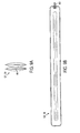
- FIG. 6 illustrates a view of an inflatable member 124 or 134 according to an illustrative embodiment of the present invention.
- the inflatable members 124 and 134 may assume other shapes and configurations consistent with the present invention.
- the comfort layer inflatable members 124 may assume shapes and/or configurations that are different from the shapes and/or configurations of the support layer inflatable members 134.
- each of the inflatable members comprises a valve 401.
- FIG. 9A illustrates a side view of one end of an inflatable member 124 or 134 according to an illustrative embodiment of the present invention.
- FIG. 9B illustrates a top view of an inflatable member 124 or 134 according to an illustrative embodiment of the present invention.
Priority Applications (2)
| Application Number | Priority Date | Filing Date | Title |
|---|---|---|---|
| PL08872303T PL2255293T3 (pl) | 2008-02-14 | 2008-11-14 | Urządzenia i sposoby do ewaluacji osoby dla systemu sypialnianego |
| EP12185566.2A EP2540194B1 (en) | 2008-02-14 | 2008-11-14 | Apparatuses and methods for evaluating a person for a sleep system |
Applications Claiming Priority (2)
| Application Number | Priority Date | Filing Date | Title |
|---|---|---|---|
| US2857808P | 2008-02-14 | 2008-02-14 | |
| PCT/US2008/083633 WO2009102362A1 (en) | 2008-02-14 | 2008-11-14 | Apparatuses and methods for evaluating a person for a sleep system |
Related Child Applications (2)
| Application Number | Title | Priority Date | Filing Date |
|---|---|---|---|
| EP12185566.2A Division EP2540194B1 (en) | 2008-02-14 | 2008-11-14 | Apparatuses and methods for evaluating a person for a sleep system |
| EP12185566.2 Division-Into | 2012-09-21 |
Publications (3)
| Publication Number | Publication Date |
|---|---|
| EP2255293A1 EP2255293A1 (en) | 2010-12-01 |
| EP2255293A4 EP2255293A4 (en) | 2011-10-12 |
| EP2255293B1 true EP2255293B1 (en) | 2012-10-31 |
Family
ID=40957215
Family Applications (2)
| Application Number | Title | Priority Date | Filing Date |
|---|---|---|---|
| EP12185566.2A Active EP2540194B1 (en) | 2008-02-14 | 2008-11-14 | Apparatuses and methods for evaluating a person for a sleep system |
| EP08872303A Active EP2255293B1 (en) | 2008-02-14 | 2008-11-14 | Apparatuses and methods for evaluating a person for a sleep system |
Family Applications Before (1)
| Application Number | Title | Priority Date | Filing Date |
|---|---|---|---|
| EP12185566.2A Active EP2540194B1 (en) | 2008-02-14 | 2008-11-14 | Apparatuses and methods for evaluating a person for a sleep system |
Country Status (16)
| Country | Link |
|---|---|
| US (1) | US8620615B2 (es) |
| EP (2) | EP2540194B1 (es) |
| JP (1) | JP5467058B2 (es) |
| KR (1) | KR101483692B1 (es) |
| CN (2) | CN105808922A (es) |
| AU (1) | AU2008350278B2 (es) |
| BR (1) | BRPI0822374A2 (es) |
| CA (1) | CA2715369C (es) |
| DK (1) | DK2255293T3 (es) |
| ES (1) | ES2397001T3 (es) |
| IL (1) | IL207594A0 (es) |
| MX (1) | MX2010008952A (es) |
| PL (1) | PL2255293T3 (es) |
| RU (2) | RU2463936C2 (es) |
| WO (1) | WO2009102362A1 (es) |
| ZA (1) | ZA201005871B (es) |
Cited By (1)
| Publication number | Priority date | Publication date | Assignee | Title |
|---|---|---|---|---|
| WO2021237258A1 (de) | 2020-05-25 | 2021-12-02 | Hans Malzl | Verfahren und vorrichtung zur individuellen anpassung der stützfunktion einer liegematratze |
Families Citing this family (61)
| Publication number | Priority date | Publication date | Assignee | Title |
|---|---|---|---|---|
| US10512575B2 (en) * | 2007-02-06 | 2019-12-24 | Deka Products Limited Partnership | Dynamic support apparatus |
| US20080077020A1 (en) | 2006-09-22 | 2008-03-27 | Bam Labs, Inc. | Method and apparatus for monitoring vital signs remotely |
| US8770020B2 (en) * | 2008-02-14 | 2014-07-08 | Kingsdown, Inc. | Methods and apparatuses for testing a sleep support member |
| WO2009102936A1 (en) * | 2008-02-14 | 2009-08-20 | Kingsdown, Inc. | Apparatuses and methods for single-sided zoned mattress rotation |
| AU2008350277B2 (en) * | 2008-02-14 | 2012-05-31 | Kingsdown, Inc. | Apparatuses and methods providing variable support and variable comfort control of a sleep system and automatic adjustment thereof |
| US8341784B2 (en) * | 2008-02-14 | 2013-01-01 | Kingsdown, Inc. | Apparatuses and methods for automatic pillow adjustment |
| WO2009108228A1 (en) * | 2008-02-25 | 2009-09-03 | Kingsdown, Inc. | Systems and methods for controlling a bedroom environment and for providing sleep data |
| US20110010249A1 (en) * | 2008-03-21 | 2011-01-13 | Oexman Robert D | Methods and apparatuses for providing a sleep system having customized zoned support and zoned comfort |
| MX2010014564A (es) * | 2008-06-26 | 2011-02-15 | Kingsdown Inc | Metodos y aparatos para el analisis de la comodidad/soporte de un miembro de soporte para dormir. |
| US9592005B2 (en) * | 2010-01-29 | 2017-03-14 | Dreamwell, Ltd. | Systems and methods for bedding with sleep diagnostics |
| US8458042B1 (en) | 2011-03-02 | 2013-06-04 | King Koil Licensing Company, Inc. | Methods for selecting a bedding mattress |
| WO2013079118A1 (en) * | 2011-12-01 | 2013-06-06 | Kayfoam Woolfson | A system for determining optimal mattress characteristics for individuals |
| US20150128353A1 (en) * | 2012-09-10 | 2015-05-14 | Boyd Thomas Kildey | Sleep monitoring system and method |
| DK2745745T3 (da) * | 2012-12-19 | 2020-01-20 | Starsprings Ab | Seng med automatisk justerbare egenskaber |
| US9566031B2 (en) | 2013-01-30 | 2017-02-14 | Kingsdown, Inc. | Apparatuses and methods for measured sleep alarm signaling |
| US8984687B2 (en) | 2013-03-14 | 2015-03-24 | Select Comfort Corporation | Partner snore feature for adjustable bed foundation |
| EP2967224B2 (en) | 2013-03-14 | 2023-02-22 | Select Comfort Corporation | Inflatable air mattress system with detection techniques |
| CN105517464B (zh) | 2013-03-14 | 2018-12-21 | 数眠公司 | 充气式空气床垫打鼾检测和响应 |
| US9844275B2 (en) | 2013-03-14 | 2017-12-19 | Select Comfort Corporation | Inflatable air mattress with light and voice controls |
| CA2905987C (en) | 2013-03-14 | 2018-02-13 | Select Comfort Corporation | Inflatable air mattress autofill and off bed pressure adjustment |
| EP2967226B1 (en) | 2013-03-14 | 2018-06-27 | Select Comfort Corporation | Inflatable air mattress alert and monitoring system |
| WO2014152793A1 (en) | 2013-03-14 | 2014-09-25 | Nunn Rob | Inflatable air mattress system architecture |
| GB201305316D0 (en) * | 2013-03-22 | 2013-05-08 | Kit For Kids Ltd | Mattress |
| US9504416B2 (en) | 2013-07-03 | 2016-11-29 | Sleepiq Labs Inc. | Smart seat monitoring system |
| US9445751B2 (en) | 2013-07-18 | 2016-09-20 | Sleepiq Labs, Inc. | Device and method of monitoring a position and predicting an exit of a subject on or from a substrate |
| US10674832B2 (en) | 2013-12-30 | 2020-06-09 | Sleep Number Corporation | Inflatable air mattress with integrated control |
| CA2945694C (en) | 2013-12-30 | 2022-10-25 | Select Comfort Corporation | Inflatable air mattress with integrated control |
| BE1022380B1 (nl) | 2014-03-17 | 2016-03-18 | Custom8 Nv | Slaapsysteem |
| EP2923610B1 (en) * | 2014-03-26 | 2020-03-18 | Starsprings AB | Mattress arrangement, such as a bed, having adjustable firmness |
| US10314407B1 (en) * | 2014-04-30 | 2019-06-11 | Xsensor Technology Corporation | Intelligent sleep ecosystem |
| CN103919387B (zh) * | 2014-05-06 | 2016-03-30 | 许昌学院 | 一种坐垫、座椅与人体坐姿检测装置 |
| CA2955365C (en) | 2014-07-18 | 2023-04-04 | Select Comfort Corporation | Automatic sensing and adjustment of a bed system |
| US10448749B2 (en) | 2014-10-10 | 2019-10-22 | Sleep Number Corporation | Bed having logic controller |
| EP3242576A4 (en) | 2015-01-05 | 2018-07-25 | Select Comfort Corporation | Bed with user occupancy tracking |
| US20160244319A1 (en) * | 2015-02-19 | 2016-08-25 | Hanseatic Bedding Products, Inc. | Method of custom fitting a mattress |
| WO2016148661A1 (en) * | 2015-03-13 | 2016-09-22 | Iskeçeli Çelik Yay Tel Yan Ürünleri Sanayi Ve Ticaret Limited Şirketi | Advanced spring system for spring bearings |
| CN104799613B (zh) * | 2015-03-25 | 2017-10-24 | 安徽农业大学 | 一种无干扰识别和记录睡眠行为的健康分区床垫及应用 |
| US10149549B2 (en) | 2015-08-06 | 2018-12-11 | Sleep Number Corporation | Diagnostics of bed and bedroom environment |
| CN105117007B (zh) * | 2015-08-20 | 2019-02-12 | 小米科技有限责任公司 | 显示设备的控制方法、装置及智能垫体 |
| CN105203417A (zh) * | 2015-09-23 | 2015-12-30 | 成都多力多新材料有限公司 | 一种沙发硬度定制检测装置 |
| JP6229983B2 (ja) * | 2015-12-16 | 2017-11-15 | 株式会社エムール | 寝具選択システム及び寝具物性認識システム |
| US10561253B2 (en) * | 2016-07-29 | 2020-02-18 | Bryte, Inc. | Adaptive sleep system using data analytics and learning techniques to improve individual sleep conditions |
| ES2610795B1 (es) * | 2016-10-17 | 2017-10-30 | Descansare Sleep Lab, S.L. | Método y sistema de mejora de la calidad del sueño, y colchón que comprende el sistema |
| BE1024394B1 (nl) | 2016-12-14 | 2018-02-07 | Custom8 Nv | Steunmodule voor een adaptief slaapsysteem en adaptief slaapsysteem |
| EP3403540B1 (en) * | 2017-05-15 | 2020-03-18 | Starsprings AB | Mattress arrangement, such as a bed, having adjustable firmness |
| CN108309233B (zh) * | 2017-12-21 | 2020-07-10 | 速眠创新科技(深圳)有限公司 | 睡眠质量监测方法、系统、计算机设备和存储介质 |
| US11737938B2 (en) | 2017-12-28 | 2023-08-29 | Sleep Number Corporation | Snore sensing bed |
| EP3735155A4 (en) * | 2018-01-04 | 2021-10-06 | IKEA Supply AG | REINFORCED POCKET SPRING MATTRESS |
| RU188577U1 (ru) * | 2018-03-21 | 2019-04-17 | Общество С Ограниченной Ответственностью "Овис" | Устройство для очистки и регенерации воздуха |
| CN108648039A (zh) * | 2018-04-20 | 2018-10-12 | 麒盛科技股份有限公司 | 一种电动床智能体验推荐方法及其应用系统 |
| CN110533493A (zh) * | 2018-05-23 | 2019-12-03 | 佛山市黛富妮家饰用品有限公司 | 床垫选择方法及其电子装置 |
| DE102018127734A1 (de) * | 2018-11-07 | 2020-05-07 | Sven Oliver Maier | Verfahren zur Herstellung einer personenspezifischen Matratze |
| KR102115501B1 (ko) * | 2018-12-04 | 2020-05-26 | 김정은 | 바디케어 모션 트래킹 장치 및 이를 이용한 바디케어 관리 방법 |
| JP6976387B2 (ja) * | 2019-04-19 | 2021-12-08 | パラマウントベッド株式会社 | 評価装置及びプログラム |
| CN110515308A (zh) * | 2019-09-26 | 2019-11-29 | 深圳市酷开网络科技有限公司 | 寝具控制方法、寝具控制装置和可读存储介质 |
| CN110991113B (zh) * | 2019-11-29 | 2023-03-31 | 大自然科技股份有限公司 | 一种棕床垫轻量化双层结构的设计方法 |
| CN110991035B (zh) * | 2019-11-29 | 2023-05-05 | 大自然科技股份有限公司 | 一种棕床垫轻量化结构的设计方法 |
| CN110990970B (zh) * | 2019-11-29 | 2023-04-18 | 大自然科技股份有限公司 | 一种棕床垫轻量化结构的设计及检测方法 |
| US11627911B2 (en) * | 2020-04-03 | 2023-04-18 | The Hong Kong Research Institute Of Textiles And Apparel Limited | System for evaluating sleeping comfort of bedding system |
| CN111887866B (zh) * | 2020-06-11 | 2022-09-23 | 杭州师范大学 | 坐垫式实时多动症监测系统及方法 |
| CN113796851B (zh) * | 2021-09-30 | 2024-03-22 | 喜临门家具股份有限公司 | 一种呼吸正异常识别方法及装置 |
Family Cites Families (75)
| Publication number | Priority date | Publication date | Assignee | Title |
|---|---|---|---|---|
| US3462778A (en) * | 1966-02-25 | 1969-08-26 | Gaymar Ind Inc | Inflatable mattress and pressure system |
| US3786676A (en) * | 1972-10-18 | 1974-01-22 | Goodrich Co B F | Compression testing machine |
| US4466385A (en) * | 1983-10-03 | 1984-08-21 | Combustion Engineering, Inc. | Support for in-bed heat exchanger |
| US4501034A (en) | 1983-10-27 | 1985-02-26 | Greenawalt Monte H | Inflatable pillow |
| JPS60258884A (ja) * | 1984-06-06 | 1985-12-20 | 松下電器産業株式会社 | 就寝用採暖具 |
| US4827763A (en) * | 1986-04-11 | 1989-05-09 | Purdue Research Foundation | Pressure mapping system with capacitive measuring pad |
| US4982466A (en) * | 1988-10-12 | 1991-01-08 | Leggett & Platt, Incorporated | Body support system |
| JP2933173B2 (ja) * | 1990-01-30 | 1999-08-09 | 高木産業株式会社 | 寝具選定方法及びその装置 |
| US5062169A (en) * | 1990-03-09 | 1991-11-05 | Leggett & Platt, Incorporated | Clinical bed |
| US5060174A (en) * | 1990-04-18 | 1991-10-22 | Biomechanics Corporation Of America | Method and apparatus for evaluating a load bearing surface such as a seat |
| US5105488A (en) * | 1990-04-18 | 1992-04-21 | Simmons Company | Bedding configuration having variable support characteristics |
| WO1992008398A1 (en) * | 1990-11-13 | 1992-05-29 | Leggett & Platt, Incorporated | Bedding system |
| US5170364A (en) * | 1990-12-06 | 1992-12-08 | Biomechanics Corporation Of America | Feedback system for load bearing surface |
| US5148706A (en) * | 1991-05-29 | 1992-09-22 | France Bed Co., Ltd. | Apparatus for selecting mattress |
| RU2009660C1 (ru) * | 1992-06-30 | 1994-03-30 | Александр Михайлович Зеленин | Кушетка |
| CA2073424A1 (en) * | 1992-07-08 | 1994-01-09 | Robert D. J. Gabelhouse | Equilibrium bed |
| GB9320864D0 (en) * | 1993-10-11 | 1993-12-01 | Scales John T | Assessment of patient support systems |
| CA2156685C (en) * | 1995-08-22 | 1997-12-23 | Yu Chun Hsia | Temperature and pressure control means for water bed |
| US5636396A (en) * | 1995-10-04 | 1997-06-10 | L&P Property Management Company | Inner spring border firmness adjuster |
| US6115861A (en) * | 1997-10-09 | 2000-09-12 | Patmark Company, Inc. | Mattress structure |
| US5848450A (en) * | 1996-03-05 | 1998-12-15 | L&P Property Management Company | Air bed control |
| US5989258A (en) * | 1997-09-16 | 1999-11-23 | Hattori; Morihiro | Apparatus for and method of bone drilling |
| AU3463199A (en) * | 1998-03-31 | 1999-10-18 | Hill-Rom, Inc. | Air-over-foam mattress |
| US5948303A (en) * | 1998-05-04 | 1999-09-07 | Larson; Lynn D. | Temperature control for a bed |
| DE69905165T2 (de) * | 1998-06-03 | 2003-11-27 | Magna Interior Sys Inc | Verfahren zur flächenhaften druckerfassung für die bestimmung des komforts von fahrzeugsitzen |
| US6226792B1 (en) * | 1998-10-14 | 2001-05-01 | Unisys Corporation | Object management system supporting the use of application domain knowledge mapped to technology domain knowledge |
| US5987675A (en) * | 1998-10-15 | 1999-11-23 | Kim; Susan Young-Sook | Spinal support and stretch pillow system |
| JP2000189472A (ja) | 1998-10-22 | 2000-07-11 | Denso Corp | 床ずれ防止装置 |
| GB9905005D0 (en) | 1999-03-05 | 1999-04-28 | Bain Duncan S | Portable device for the assessment of mattresses |
| AU4215200A (en) * | 1999-04-07 | 2000-10-23 | L&P Property Management Company | Customized mattress system |
| US6269505B1 (en) * | 1999-04-20 | 2001-08-07 | M.P.L. Ltd. | Inflatable cushioning device with manifold system |
| DE29917813U1 (de) * | 1999-10-08 | 2001-02-22 | Westmont Technik Gmbh & Co Kg | Verstellvorrichtung für Betten, Matratzen, Sessel u.dgl. |
| US6327725B1 (en) * | 1999-12-14 | 2001-12-11 | S.V.M. Orthopedic Solutions Inc. | Pillow with adjustable neck support |
| US6468234B1 (en) * | 2000-07-14 | 2002-10-22 | The Board Of Trustees Of The Leland Stanford Junior University | SleepSmart |
| WO2002019872A1 (en) * | 2000-09-05 | 2002-03-14 | Levy Zur | Pressure relief pneumatic area support device |
| US6571192B1 (en) | 2000-11-28 | 2003-05-27 | W. Eric Hinshaw | Automatic mattress selection system |
| TW526056B (en) | 2001-03-15 | 2003-04-01 | Huntleigh Technology Plc | Inflatable support |
| US6698046B1 (en) * | 2001-03-26 | 2004-03-02 | Sunflower Medical, L.L.C. | Air mattress control unit |
| US6916236B2 (en) * | 2001-06-13 | 2005-07-12 | Terpstra Enterprises Pty Ltd. | Extraction apparatus |
| US6984427B2 (en) | 2002-01-10 | 2006-01-10 | 3M Innovative Properties Company | Microstructed release liner |
| NL1022279C1 (nl) * | 2002-03-04 | 2003-09-05 | Jan Koops | Hoofdkussen voor het tegengaan van snurken. |
| US6662393B2 (en) * | 2002-03-19 | 2003-12-16 | Dennis Boyd | Composite mattress |
| EP1492434A1 (en) | 2002-04-11 | 2005-01-05 | CHAFFEE, Robert B. | Body support surface comfort device |
| US7036172B2 (en) * | 2002-06-01 | 2006-05-02 | Sleepadvantage, Lc | Bed having low body pressure and alignment |
| US20040139549A1 (en) * | 2002-10-28 | 2004-07-22 | Hassan Mohrekesh | Automatically adjustable pillow |
| US6878121B2 (en) * | 2002-11-01 | 2005-04-12 | David T. Krausman | Sleep scoring apparatus and method |
| CN100376187C (zh) * | 2003-03-12 | 2008-03-26 | 镇泰有限公司 | 可调节的床垫和枕垫系统 |
| US7524279B2 (en) | 2003-12-31 | 2009-04-28 | Raphael Auphan | Sleep and environment control method and system |
| US7127758B2 (en) * | 2004-03-02 | 2006-10-31 | Gabbay Daniel S | Active head/neck positioning device for endotracheal intubation |
| WO2005104904A1 (en) | 2004-04-30 | 2005-11-10 | Tactex Controls Inc. | Body support apparatus having automatic pressure control and related methods |
| US20070235036A1 (en) | 2004-04-30 | 2007-10-11 | Bobey John A | Patient support |
| DE102004022284B3 (de) * | 2004-05-04 | 2005-12-22 | Daryoush Bazargani | Individuell ergonomisch einstellbares Kopfkissen |
| US6986182B2 (en) * | 2004-06-10 | 2006-01-17 | L&P Property Management Company | Pocketed bedding or seating product having inflatable members |
| AU2005277535A1 (en) | 2004-08-16 | 2006-03-02 | John P. Biondo | Dynamic cellular person support surface |
| US7716763B2 (en) * | 2005-02-16 | 2010-05-18 | Nissen Ipad, Llc | Apparatus and method to position a patient for airway management and endotracheal intubation |
| US20060236460A1 (en) * | 2005-03-31 | 2006-10-26 | Mark Hooper | Apparatus and method for determining an individuals pillow type |
| NZ548621A (en) * | 2005-07-19 | 2007-11-30 | Dennis M Boyd | System and method for selecting a mattress and a pillow |
| US7467058B2 (en) * | 2006-04-06 | 2008-12-16 | Dennis M. Boyd | Method and system for selecting a mattress |
| US20070021965A1 (en) | 2005-07-19 | 2007-01-25 | Boyd Dennis M | System and method for selecting a pillow |
| US7536739B2 (en) | 2005-08-10 | 2009-05-26 | Kreg Medical, Inc. | Therapeutic mattress |
| US20070056112A1 (en) * | 2005-09-09 | 2007-03-15 | Graebe Robert H | Zoned cellular cushion with fail safe inflation zones |
| TWI309343B (en) * | 2005-09-14 | 2009-05-01 | Ind Tech Res Inst | Enviromental controlling system and method thereof |
| WO2007053150A1 (en) | 2005-11-07 | 2007-05-10 | Kingsdown, Incorporated | Automatic mattress selection system |
| KR100738510B1 (ko) | 2006-02-14 | 2007-07-11 | 원광대학교산학협력단 | 수면제어장치 및 그 제어방법 |
| US20070199154A1 (en) * | 2006-02-24 | 2007-08-30 | Escaross Essam B | System and method for adjusting pressure in pockets or zones |
| CA2648001C (en) * | 2006-04-04 | 2014-12-09 | Robert B. Chaffee | Method and apparatus for monitoring and controlling pressure in an inflatable device |
| DE102006019748B4 (de) * | 2006-04-28 | 2009-11-26 | Dräger Medical AG & Co. KG | Patientenfläche zum Transportieren und/oder Lagern eines Patienten |
| US20070266497A1 (en) * | 2006-05-22 | 2007-11-22 | Shoe Kenmochi | Method of producing "one's pillows" with characteristics for a restful and restorative sleep is based on scientific basis of observing human occlusion |
| JP4905043B2 (ja) | 2006-10-12 | 2012-03-28 | アイシン精機株式会社 | ベッド装置 |
| US20090240514A1 (en) * | 2007-06-28 | 2009-09-24 | L & P Property Management Company | System and Method for Recommending a Bedding Product |
| WO2009036077A1 (en) * | 2007-09-10 | 2009-03-19 | Amerigon, Inc. | Operational control schemes for ventilated seat or bed assemblies |
| AU2008350277B2 (en) * | 2008-02-14 | 2012-05-31 | Kingsdown, Inc. | Apparatuses and methods providing variable support and variable comfort control of a sleep system and automatic adjustment thereof |
| US8341784B2 (en) * | 2008-02-14 | 2013-01-01 | Kingsdown, Inc. | Apparatuses and methods for automatic pillow adjustment |
| WO2009108228A1 (en) | 2008-02-25 | 2009-09-03 | Kingsdown, Inc. | Systems and methods for controlling a bedroom environment and for providing sleep data |
| US20110010249A1 (en) * | 2008-03-21 | 2011-01-13 | Oexman Robert D | Methods and apparatuses for providing a sleep system having customized zoned support and zoned comfort |
-
2008
- 2008-11-14 JP JP2010546748A patent/JP5467058B2/ja active Active
- 2008-11-14 RU RU2010135586/12A patent/RU2463936C2/ru active
- 2008-11-14 KR KR1020107018089A patent/KR101483692B1/ko active IP Right Grant
- 2008-11-14 CN CN201610112496.0A patent/CN105808922A/zh active Pending
- 2008-11-14 EP EP12185566.2A patent/EP2540194B1/en active Active
- 2008-11-14 PL PL08872303T patent/PL2255293T3/pl unknown
- 2008-11-14 CN CN2008801285843A patent/CN102007481A/zh active Pending
- 2008-11-14 BR BRPI0822374A patent/BRPI0822374A2/pt not_active Application Discontinuation
- 2008-11-14 US US12/867,740 patent/US8620615B2/en active Active
- 2008-11-14 ES ES08872303T patent/ES2397001T3/es active Active
- 2008-11-14 MX MX2010008952A patent/MX2010008952A/es active IP Right Grant
- 2008-11-14 AU AU2008350278A patent/AU2008350278B2/en active Active
- 2008-11-14 CA CA2715369A patent/CA2715369C/en active Active
- 2008-11-14 EP EP08872303A patent/EP2255293B1/en active Active
- 2008-11-14 WO PCT/US2008/083633 patent/WO2009102362A1/en active Application Filing
- 2008-11-14 DK DK08872303.6T patent/DK2255293T3/da active
-
2010
- 2010-08-12 IL IL207594A patent/IL207594A0/en active IP Right Grant
- 2010-08-17 ZA ZA2010/05871A patent/ZA201005871B/en unknown
-
2012
- 2012-06-25 RU RU2012126377/12A patent/RU2591109C2/ru active
Cited By (1)
| Publication number | Priority date | Publication date | Assignee | Title |
|---|---|---|---|---|
| WO2021237258A1 (de) | 2020-05-25 | 2021-12-02 | Hans Malzl | Verfahren und vorrichtung zur individuellen anpassung der stützfunktion einer liegematratze |
Also Published As
| Publication number | Publication date |
|---|---|
| AU2008350278B2 (en) | 2012-03-29 |
| PL2255293T3 (pl) | 2013-03-29 |
| EP2540194B1 (en) | 2014-04-30 |
| ES2397001T3 (es) | 2013-03-01 |
| EP2540194A1 (en) | 2013-01-02 |
| ZA201005871B (en) | 2011-04-28 |
| CA2715369A1 (en) | 2009-08-20 |
| EP2255293A4 (en) | 2011-10-12 |
| JP5467058B2 (ja) | 2014-04-09 |
| RU2012126377A (ru) | 2013-12-27 |
| MX2010008952A (es) | 2011-03-04 |
| AU2008350278A1 (en) | 2009-08-20 |
| WO2009102362A1 (en) | 2009-08-20 |
| CA2715369C (en) | 2019-01-15 |
| CN102007481A (zh) | 2011-04-06 |
| KR101483692B1 (ko) | 2015-01-16 |
| RU2463936C2 (ru) | 2012-10-20 |
| KR20100130593A (ko) | 2010-12-13 |
| DK2255293T3 (da) | 2012-12-03 |
| JP2011512192A (ja) | 2011-04-21 |
| IL207594A0 (en) | 2010-12-30 |
| BRPI0822374A2 (pt) | 2017-12-12 |
| RU2010135586A (ru) | 2012-03-20 |
| EP2255293A1 (en) | 2010-12-01 |
| CN105808922A (zh) | 2016-07-27 |
| RU2591109C2 (ru) | 2016-07-10 |
| US20100317930A1 (en) | 2010-12-16 |
| US8620615B2 (en) | 2013-12-31 |
Similar Documents
| Publication | Publication Date | Title |
|---|---|---|
| EP2255293B1 (en) | Apparatuses and methods for evaluating a person for a sleep system | |
| CA2715368C (en) | Apparatuses and methods providing variable support and variable comfort control of a sleep system and automatic adjustment thereof | |
| AU2012203791B2 (en) | Apparatuses and methods for evaluating a person for a sleep system | |
| AU2012216600B2 (en) | Apparatuses and methods providing variable support and variable comfort control of a sleep system and automatic adjustment thereof |
Legal Events
| Date | Code | Title | Description |
|---|---|---|---|
| PUAI | Public reference made under article 153(3) epc to a published international application that has entered the european phase |
Free format text: ORIGINAL CODE: 0009012 |
|
| 17P | Request for examination filed |
Effective date: 20100914 |
|
| AK | Designated contracting states |
Kind code of ref document: A1 Designated state(s): AT BE BG CH CY CZ DE DK EE ES FI FR GB GR HR HU IE IS IT LI LT LU LV MC MT NL NO PL PT RO SE SI SK TR |
|
| AX | Request for extension of the european patent |
Extension state: AL BA MK RS |
|
| DAX | Request for extension of the european patent (deleted) | ||
| A4 | Supplementary search report drawn up and despatched |
Effective date: 20110912 |
|
| RIC1 | Information provided on ipc code assigned before grant |
Ipc: G06F 15/00 20060101AFI20110906BHEP |
|
| GRAP | Despatch of communication of intention to grant a patent |
Free format text: ORIGINAL CODE: EPIDOSNIGR1 |
|
| GRAS | Grant fee paid |
Free format text: ORIGINAL CODE: EPIDOSNIGR3 |
|
| GRAA | (expected) grant |
Free format text: ORIGINAL CODE: 0009210 |
|
| AK | Designated contracting states |
Kind code of ref document: B1 Designated state(s): AT BE BG CH CY CZ DE DK EE ES FI FR GB GR HR HU IE IS IT LI LT LU LV MC MT NL NO PL PT RO SE SI SK TR |
|
| REG | Reference to a national code |
Ref country code: GB Ref legal event code: FG4D Ref country code: CH Ref legal event code: EP |
|
| REG | Reference to a national code |
Ref country code: AT Ref legal event code: REF Ref document number: 582353 Country of ref document: AT Kind code of ref document: T Effective date: 20121115 |
|
| REG | Reference to a national code |
Ref country code: RO Ref legal event code: EPE |
|
| REG | Reference to a national code |
Ref country code: DK Ref legal event code: T3 |
|
| REG | Reference to a national code |
Ref country code: NL Ref legal event code: T3 Ref country code: IE Ref legal event code: FG4D |
|
| REG | Reference to a national code |
Ref country code: SE Ref legal event code: TRGR |
|
| REG | Reference to a national code |
Ref country code: DE Ref legal event code: R096 Ref document number: 602008019881 Country of ref document: DE Effective date: 20121227 |
|
| REG | Reference to a national code |
Ref country code: NO Ref legal event code: T2 Effective date: 20121031 |
|
| REG | Reference to a national code |
Ref country code: ES Ref legal event code: FG2A Ref document number: 2397001 Country of ref document: ES Kind code of ref document: T3 Effective date: 20130301 |
|
| REG | Reference to a national code |
Ref country code: LT Ref legal event code: MG4D |
|
| REG | Reference to a national code |
Ref country code: PL Ref legal event code: T3 |
|
| PG25 | Lapsed in a contracting state [announced via postgrant information from national office to epo] |
Ref country code: HR Free format text: LAPSE BECAUSE OF FAILURE TO SUBMIT A TRANSLATION OF THE DESCRIPTION OR TO PAY THE FEE WITHIN THE PRESCRIBED TIME-LIMIT Effective date: 20121031 Ref country code: LT Free format text: LAPSE BECAUSE OF FAILURE TO SUBMIT A TRANSLATION OF THE DESCRIPTION OR TO PAY THE FEE WITHIN THE PRESCRIBED TIME-LIMIT Effective date: 20121031 |
|
| PG25 | Lapsed in a contracting state [announced via postgrant information from national office to epo] |
Ref country code: PT Free format text: LAPSE BECAUSE OF FAILURE TO SUBMIT A TRANSLATION OF THE DESCRIPTION OR TO PAY THE FEE WITHIN THE PRESCRIBED TIME-LIMIT Effective date: 20130228 Ref country code: SI Free format text: LAPSE BECAUSE OF FAILURE TO SUBMIT A TRANSLATION OF THE DESCRIPTION OR TO PAY THE FEE WITHIN THE PRESCRIBED TIME-LIMIT Effective date: 20121031 Ref country code: LV Free format text: LAPSE BECAUSE OF FAILURE TO SUBMIT A TRANSLATION OF THE DESCRIPTION OR TO PAY THE FEE WITHIN THE PRESCRIBED TIME-LIMIT Effective date: 20121031 Ref country code: GR Free format text: LAPSE BECAUSE OF FAILURE TO SUBMIT A TRANSLATION OF THE DESCRIPTION OR TO PAY THE FEE WITHIN THE PRESCRIBED TIME-LIMIT Effective date: 20130201 |
|
| PG25 | Lapsed in a contracting state [announced via postgrant information from national office to epo] |
Ref country code: SK Free format text: LAPSE BECAUSE OF FAILURE TO SUBMIT A TRANSLATION OF THE DESCRIPTION OR TO PAY THE FEE WITHIN THE PRESCRIBED TIME-LIMIT Effective date: 20121031 Ref country code: BG Free format text: LAPSE BECAUSE OF FAILURE TO SUBMIT A TRANSLATION OF THE DESCRIPTION OR TO PAY THE FEE WITHIN THE PRESCRIBED TIME-LIMIT Effective date: 20130131 Ref country code: EE Free format text: LAPSE BECAUSE OF FAILURE TO SUBMIT A TRANSLATION OF THE DESCRIPTION OR TO PAY THE FEE WITHIN THE PRESCRIBED TIME-LIMIT Effective date: 20121031 |
|
| PLBE | No opposition filed within time limit |
Free format text: ORIGINAL CODE: 0009261 |
|
| STAA | Information on the status of an ep patent application or granted ep patent |
Free format text: STATUS: NO OPPOSITION FILED WITHIN TIME LIMIT |
|
| 26N | No opposition filed |
Effective date: 20130801 |
|
| REG | Reference to a national code |
Ref country code: HU Ref legal event code: AG4A Ref document number: E016885 Country of ref document: HU |
|
| REG | Reference to a national code |
Ref country code: DE Ref legal event code: R097 Ref document number: 602008019881 Country of ref document: DE Effective date: 20130801 |
|
| PG25 | Lapsed in a contracting state [announced via postgrant information from national office to epo] |
Ref country code: MT Free format text: LAPSE BECAUSE OF FAILURE TO SUBMIT A TRANSLATION OF THE DESCRIPTION OR TO PAY THE FEE WITHIN THE PRESCRIBED TIME-LIMIT Effective date: 20121031 Ref country code: CY Free format text: LAPSE BECAUSE OF FAILURE TO SUBMIT A TRANSLATION OF THE DESCRIPTION OR TO PAY THE FEE WITHIN THE PRESCRIBED TIME-LIMIT Effective date: 20121031 |
|
| PG25 | Lapsed in a contracting state [announced via postgrant information from national office to epo] |
Ref country code: MC Free format text: LAPSE BECAUSE OF NON-PAYMENT OF DUE FEES Effective date: 20121130 |
|
| REG | Reference to a national code |
Ref country code: FR Ref legal event code: PLFP Year of fee payment: 8 |
|
| REG | Reference to a national code |
Ref country code: FR Ref legal event code: PLFP Year of fee payment: 9 |
|
| REG | Reference to a national code |
Ref country code: FR Ref legal event code: PLFP Year of fee payment: 10 |
|
| PGFP | Annual fee paid to national office [announced via postgrant information from national office to epo] |
Ref country code: ES Payment date: 20230125 Year of fee payment: 15 |
|
| P01 | Opt-out of the competence of the unified patent court (upc) registered |
Effective date: 20230530 |
|
| PGFP | Annual fee paid to national office [announced via postgrant information from national office to epo] |
Ref country code: NL Payment date: 20231120 Year of fee payment: 16 Ref country code: LU Payment date: 20231120 Year of fee payment: 16 |
|
| PGFP | Annual fee paid to national office [announced via postgrant information from national office to epo] |
Ref country code: GB Payment date: 20231123 Year of fee payment: 16 |
|
| PGFP | Annual fee paid to national office [announced via postgrant information from national office to epo] |
Ref country code: IS Payment date: 20231110 Year of fee payment: 16 |
|
| PGFP | Annual fee paid to national office [announced via postgrant information from national office to epo] |
Ref country code: TR Payment date: 20231113 Year of fee payment: 16 Ref country code: SE Payment date: 20231120 Year of fee payment: 16 Ref country code: RO Payment date: 20231102 Year of fee payment: 16 Ref country code: NO Payment date: 20231124 Year of fee payment: 16 Ref country code: IT Payment date: 20231124 Year of fee payment: 16 Ref country code: IE Payment date: 20231017 Year of fee payment: 16 Ref country code: HU Payment date: 20231122 Year of fee payment: 16 Ref country code: FR Payment date: 20231120 Year of fee payment: 16 Ref country code: FI Payment date: 20231121 Year of fee payment: 16 Ref country code: DK Payment date: 20231124 Year of fee payment: 16 Ref country code: DE Payment date: 20231121 Year of fee payment: 16 Ref country code: CZ Payment date: 20231106 Year of fee payment: 16 Ref country code: CH Payment date: 20231201 Year of fee payment: 16 Ref country code: AT Payment date: 20231121 Year of fee payment: 16 |
|
| PGFP | Annual fee paid to national office [announced via postgrant information from national office to epo] |
Ref country code: PL Payment date: 20231103 Year of fee payment: 16 Ref country code: BE Payment date: 20231120 Year of fee payment: 16 |
|
| PGFP | Annual fee paid to national office [announced via postgrant information from national office to epo] |
Ref country code: ES Payment date: 20240126 Year of fee payment: 16 |