EP2255154B1 - Verfahren zur herstellung einer patrone mit einem treibkäfiggeschoss hergestellt nach diesem verfahren - Google Patents
Verfahren zur herstellung einer patrone mit einem treibkäfiggeschoss hergestellt nach diesem verfahren Download PDFInfo
- Publication number
- EP2255154B1 EP2255154B1 EP09721311A EP09721311A EP2255154B1 EP 2255154 B1 EP2255154 B1 EP 2255154B1 EP 09721311 A EP09721311 A EP 09721311A EP 09721311 A EP09721311 A EP 09721311A EP 2255154 B1 EP2255154 B1 EP 2255154B1
- Authority
- EP
- European Patent Office
- Prior art keywords
- projectile
- sealing ring
- casing cover
- casing
- area
- Prior art date
- Legal status (The legal status is an assumption and is not a legal conclusion. Google has not performed a legal analysis and makes no representation as to the accuracy of the status listed.)
- Active
Links
Images
Classifications
-
- F—MECHANICAL ENGINEERING; LIGHTING; HEATING; WEAPONS; BLASTING
- F42—AMMUNITION; BLASTING
- F42B—EXPLOSIVE CHARGES, e.g. FOR BLASTING, FIREWORKS, AMMUNITION
- F42B5/00—Cartridge ammunition, e.g. separately-loaded propellant charges
- F42B5/02—Cartridges, i.e. cases with charge and missile
- F42B5/18—Caseless ammunition; Cartridges having combustible cases
- F42B5/188—Manufacturing processes therefor
-
- F—MECHANICAL ENGINEERING; LIGHTING; HEATING; WEAPONS; BLASTING
- F42—AMMUNITION; BLASTING
- F42B—EXPLOSIVE CHARGES, e.g. FOR BLASTING, FIREWORKS, AMMUNITION
- F42B5/00—Cartridge ammunition, e.g. separately-loaded propellant charges
- F42B5/02—Cartridges, i.e. cases with charge and missile
- F42B5/18—Caseless ammunition; Cartridges having combustible cases
- F42B5/181—Caseless ammunition; Cartridges having combustible cases consisting of a combustible casing wall and a metal base; Connectors therefor
-
- F—MECHANICAL ENGINEERING; LIGHTING; HEATING; WEAPONS; BLASTING
- F42—AMMUNITION; BLASTING
- F42B—EXPLOSIVE CHARGES, e.g. FOR BLASTING, FIREWORKS, AMMUNITION
- F42B5/00—Cartridge ammunition, e.g. separately-loaded propellant charges
- F42B5/02—Cartridges, i.e. cases with charge and missile
- F42B5/18—Caseless ammunition; Cartridges having combustible cases
- F42B5/192—Cartridge cases characterised by the material of the casing wall
Definitions
- the invention relates to a method for producing a cartridge having a projectile and a combustible propellant charge sleeve and a sleeve cover connecting the propellant charge sleeve to the projectile, the projectile having a sealing ring adjacent to the sleeve cover.
- the invention further relates to a cartridge with a sabot projectile made by this method. Such a method is known from EP 1 586 852 A1 ,
- a sleeve cover which may consist of a combustible material (for example nitrated plastic-impregnated cardboard) or an inert material (for example non-nitrated plastic-impregnated cardboard).
- tank ammunition requires a ductile sealing tape to prevent any propellant gases from passing the missile as it passes through the corresponding gun barrel.
- the sleeve cover is connected, for example via a screw or an adhesive connection with the rear-side portion of the projectile body, while the metal or plastic existing separate sealing ring is either pressed or injected into a designated annular groove of the projectile and then has to be post-treated.
- the invention has for its object to provide a method of the type mentioned, which compared to comparable known methods for the preparation of Cartridges with sleeve cover allows a more cost-effective installation.
- a cartridge with a sabot projectile to be disclosed which is produced by this method.
- the invention is based essentially on the idea to produce the sleeve cover as an injection molded part made of an elastic plastic, wherein the projectile facing the front side portion of the sleeve cover forms the sealing ring of the projectile.
- the integration of the sealing ring in the sleeve cover not only a simple assembly of the cartridge is possible, but by replacing the used in known cartridges, relatively brittle and abrasion-sensitive material for the sleeve cover by an elastic plastic is also the whole of sleeve cover, projectile and propellant charge existing arrangement with environmental pollution less prone to breakage and cracking than corresponding known arrangements, since the elastic plastic absorbs deformation energy.
- there is no inadvertent ignition of the sleeve cover when a sleeve cover made of plastic if this is rubbed during loading and unloading of parts of the corresponding weapon.
- a required in known sleeve covers protective coating can be omitted as a rule.
- the sleeve cover should preferably be provided with an annular predetermined breaking point between the region serving as a sealing ring and the region adjoining it at the rear, so that upon firing the sleeve cover during threading of the projectile into the caliber region of a corresponding weapon barrel is separated along the predetermined breaking points. The remains of the sleeve cover remaining in the charge space region of the weapon barrel are then expelled from the tube by the propellant charge gases on the outlet side.
- the serving as a sealing ring portion of the sleeve cover can be pressed or shrunk onto the projectile or attached by means of an adhesive bond to the projectile.
- the serving as a sealing ring portion of the sleeve cover is fixed to the projectile by a lock nut.
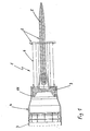
- Fig. 1 1 denotes a cartridge which can be fired from a large-caliber smooth-bore gun and which comprises a sabot projectile 2, a propellant charge sleeve 3 indicated only by dashed lines and a sleeve cover 4 connecting the propellant charge shell 3 and the sabot 2.
- the sabot projectile 2 essentially consists of a subcaliber penetrator 5 and a disposable sabot 6.
- the sabot 6 in this exemplary embodiment is a shock-absorbing cage with a plate-shaped driving element 7 acting on the rear side of the subcaliber penetrator 5.
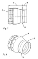
- the sleeve cover 4 is an injection-molded part made of an elastic plastic whose front-side region 8 (FIG. Fig. 2 ) surrounds the drive element 7 of the sabot 6 on the outside and forms the sealing ring of the sabot projectile 2.
- annular predetermined breaking point 10 is provided between the sealing ring 8 and the adjoining rear region 9. This is advantageously arranged so that it is in loaded in a gun barrel cartridge 1 in the region of the cone transition to the cargo space of the corresponding weapon, so that when firing the sleeve cover 4 when threading the sabot projectile 2 in the caliber area of the corresponding gun barrel along the predetermined breaking points 10 separated becomes. The remains of the sleeve cover 4 remaining in the charge space region of the weapon barrel are subsequently expelled from the tube by the propellant charge gases on the outlet side.
- the sleeve cover 4 is attached to the sabot floor 2 by a screwed onto the plate-shaped driving element 7 rear side lock nut 11.
- the cartridge does not necessarily have to be one with a stator-stabilized sabot projectile.
- the method according to the invention can also be used, for example, in cartridges with guide-stabilized bullet-shaped bodies.
- the attachment of serving as a sealing ring portion of the sleeve cover can be done on the usually conically shaped portion of the projectile body facing Leitmaschinens.
Landscapes
- Engineering & Computer Science (AREA)
- General Engineering & Computer Science (AREA)
- Manufacturing & Machinery (AREA)
- Aiming, Guidance, Guns With A Light Source, Armor, Camouflage, And Targets (AREA)
- Injection Moulding Of Plastics Or The Like (AREA)
- Portable Nailing Machines And Staplers (AREA)
Description
- Die Erfindung betrifft ein Verfahren zur Herstellung einer Patrone mit einem Geschoss und einer verbrennbaren Treibladungshülse sowie einem die Treibladungshülse mit dem Geschoss verbindenden Hülsendeckel, wobei das Geschoss einen dem Hülsendeckel benachbarten Dichtungsring aufweist. Die Erfindung bezieht sich ferner auf eine Patrone mit einem Treibkäfiggeschoss, hergestellt nach diesem Verfahren. Ein solches Verfahren ist bekannt aus
EP 1 586 852 - A1 . - Insbesondere bei großkalibriger Panzermunition mit verbrennbarer Treibladungshülse erfolgt die Anbindung der Treibladungshülse an das Geschoss üblicherweise mittels eines Hülsendeckels, der aus einem verbrennbaren Material (beispielsweise nitrierter kunststoffgetränkter Pappe) oder einem inerten Material (beispielsweise nicht nitrierter kunststoffgetränkter Pappe) bestehen kann. Außerdem erfordert Panzermunition ein verformbares Dichtungsband, damit an dem Geschoss bei seinem Durchgang durch das entsprechende Waffenrohr keine Treibladungsgase vorbeiströmen.
- Nachteilig ist bei den bekannten Verfahren unter anderem, dass die Montage der Patronen relativ zeit- und kostenaufwendig ist, da für die Montage des Hülsendeckels und die Montage des Dichtungsringes separate Fertigungslinien erforderlich sind. So wird der Hülsendeckel beispielsweise über eine Verschraubung oder eine Klebeverbindung mit dem heckseitigen Bereich des Geschosskörpers verbunden, während der aus Metall oder Kunststoff bestehende separate Dichtring entweder in eine hierfür vorgesehene Ringnut des Geschosses eingepresst oder eingespritzt wird und anschließend nachbehandelt werden muss.
- Der Erfindung liegt die Aufgabe zugrunde, ein Verfahren der eingangs erwähnten Art anzugeben, welches gegenüber vergleichbaren bekannten Verfahren zur Herstellung von Patronen mit Hülsendeckel eine kostengünstigere Montage ermöglicht. Außerdem soll eine Patrone mit einem Treibkäfiggeschoss offenbart werden, die nach diesem Verfahren hergestellt wird.
- Diese Aufgabe wird erfindungsgemäß hinsichtlich des Verfahrens durch die Merkmale des Anspruchs 1 und hinsichtlich der Patrone durch die Merkmale des Anspruchs 3 gelöst. Weitere, besonders vorteilhafte Ausgestaltungen der Erfindung offenbaren die Unteransprüche.
- Die Erfindung beruht im Wesentlichen auf dem Gedanken, den Hülsendeckel als Spritzgussteil aus einem elastischen Kunststoff herzustellen, wobei der dem Geschoss zugewandte vorderseitige Bereich des Hülsendeckels den Dichtungsring des Geschosses bildet.
- Durch die Integration des Dichtungsringes in den Hülsendeckel wird nicht nur eine einfache Montage der Patrone ermöglicht, sondern durch das Ersetzen des bei bekannten Patronen benutzten, relativ spröden und abriebempfindlichen Materials für den Hülsendeckel durch einen elastischen Kunststoff ist auch die gesamte aus Hülsendeckel, Geschoss und Treibladungshülse bestehende Anordnung bei Umweltbelastungen weniger bruch- und rissanfällig als entsprechende bekannte Anordnungen, da der elastische Kunststoff Verformungsenergie aufnimmt. Außerdem erfolgt bei einem aus Kunststoff bestehenden Hülsendeckel keine unbeabsichtigte Entzündung des Hülsendeckels, wenn dieser beim Laden und Entladen an Teilen der entsprechenden Waffe gerieben wird. Ferner kann eine bei bekannten Hülsendeckeln benötigte Schutzlackierung in der Regel entfallen.
- Vorzugsweise sollte der Hülsendeckel zwischen dem als Dichtungsring dienenden Bereich und dem sich daran heckseitig anschließenden Bereich mit einer ringförmigen Sollbruchstelle versehen werden, damit bei Schussabgabe der Hülsendeckel beim Einfädeln des Geschosses in den Kaliberbereich eines entsprechenden Waffenrohres entlang der Sollbruchstellen getrennt wird. Die im Ladungsraumbereich des Waffenrohres dabei verbleibenden Reste des Hülsendeckels werden anschließend durch die Treibladungsgase mündungsseitig aus dem Rohr herausgestoßen.
- Der als Dichtungsring dienende Bereich des Hülsendeckels kann auf das Geschoss aufgepresst oder aufgeschrumpft oder mittels einer Klebeverbindung an dem Geschoss befestigt werden.
- Es kann auch vorgesehen werden, dass der als Dichtungsring dienende Bereich des Hülsendeckels an dem Geschoss durch eine Kontermutter befestigt wird.
- Weitere Einzelheiten und Vorteile der Erfindung ergeben sich aus den folgenden, anhand von Figuren erläuterten Ausführungsbeispielen. Es zeigen:
- Fig. 1
- den Längsschnitt durch den geschossseitigen Teil einer erfindungsgemäßen Patrone mit einem Treibkäfiggeschoss und einem Hülsendeckel;
- Fig. 2
- eine vergrößerte Ansicht des in
Fig. 1 dargestellten Hülsendeckels und - Fig. 3
- eine perspektivische Ansicht des in
Fig. 2 dargestellten Hülsendeckels. - In
Fig. 1 ist mit 1 eine aus einer großkalibrigen Glattrohrkanone verschießbare Patrone bezeichnet, die ein Treibkäfiggeschoss 2, eine nur gestrichelt angedeutete Treibladungshülse 3 und einen die Treibladungshülse 3 und das Treibkäfiggeschoss 2 verbindenden Hülsendeckel 4 umfasst. Dabei setzt sich das Treibkäfiggeschoss 2 im Wesentlichen aus einem unterkalibrigen Penetrator 5 und einem abwerfbaren Treibkäfig 6 zusammen. Bei dem Treibkäfig 6 handelt es sich bei diesem Ausführungsbeispiel um einen Stoßtreibkäfig mit einem heckseitig auf den unterkalibrigen Penetrator 5 wirkenden plattenförmigen Treibelement 7. - Erfindungsgemäß handelt es sich bei dem Hülsendeckel 4 um ein Spritzgussteil aus einem elastischen Kunststoff, dessen vorderseitiger Bereich 8 (
Fig. 2 ) das Treibelement 7 des Treibkäfigs 6 außenseitig umschließt und den Dichtungsring des Treibkäfiggeschosses 2 bildet. - Um bei Schussabgabe ein definiertes Ablösen des Treibkäfiggeschosses 2 von der Treibladungshülse 3 sicherzustellen, ist zwischen dem Dichtungsring 8 und dem sich daran anschließenden heckseitigen Bereich 9 eine ringförmige Sollbruchstelle 10 vorgesehen. Diese wird vorteilhafterweise derart angeordnet, dass sie sich bei in einer Rohrwaffe geladenen Patrone 1 im Bereich des Konusüberganges zum Ladungsraum der entsprechenden Waffe befindet, so dass bei Schussabgabe der Hülsendeckel 4 beim Einfädeln des Treibkäfiggeschosses 2 in den Kaliberbereich des entsprechenden Waffenrohres entlang der Sollbruchstellen 10 getrennt wird. Die im Ladungsraumbereich des Waffenrohres dabei verbleibenden Reste des Hülsendeckels 4 werden anschließend durch die Treibladungsgase mündungsseitig aus dem Rohr herausgestoßen.
- Wie
Fig. 1 entnehmbar, ist bei dem dargestellten Ausführungsbeispiel der Hülsendeckel 4 an dem Treibkäfiggeschoss 2 durch eine auf das plattenförmige Treibelement 7 heckseitig aufgeschraubte Kontermutter 11 befestigt. - Die Erfindung ist selbstverständlich nicht auf das vorstehend beschriebene Ausführungsbeispiel beschränkt. So muss es sich bei der Patrone nicht zwingend um eine solche mit leitwerkstabilisiertem Treibkäfiggeschoss handeln. Vielmehr kann das erfindungsgemäße Verfahren beispielsweise auch bei Patronen mit leitwerkstabilisiertem kalibergleichen Geschosskörper verwendet werden. In diesem Fall kann die Befestigung des als Dichtungsring dienenden Bereiches des Hülsendeckels an dem üblicherweise kegelförmig ausgebildeten Bereich des dem Geschosskörper zugewandten Leitwerkträgers erfolgen.
-
- 1
- Patrone
- 2
- Treibkäfiggeschoss, Geschoss
- 3
- Treibladungshülse
- 4
- Hülsendeckel, Spritzgussteil
- 5
- Penetrator
- 6
- Treibkäfig
- 7
- Treibelement
- 8
- Bereich, Dichtungsring
- 9
- heckseitige Bereich
- 10
- Sollbruchstelle
- 11
- Kontermutter
Claims (4)
- Verfahren zur Herstellung einer Patrone (1) mit einem Geschoss (2) und einer verbrennbaren Treibladungshülse (3) sowie einem die Treibladungshülse (3) mit dem Geschoss (2) verbindenden Hülsendeckel (4), wobei das Geschoss (2) einen dem Hülsendeckel (4) benachbarten Dichtungsring (8) aufweist, mit den Schritten• Herstellung des Hülsendeckels (4) durch Spritzgießen mit einem elastischen Kunststoff, wobei der Dichtungsring durch den dem Geschoss (2) zugewandten vorderseitigen Bereich (8) des Hülsendeckels (4) gebildet wird,• verbinden des Hülsendeckel (4) mit der Treibladungshülse (3) und dem Geschoss (2), wobei• der Hülsendeckel (4) zwischen dem den Dichtungsring bildenden Bereich (8) und dem sich daran anschließenden heckseitigen Bereich (9) mit einer ringförmigen Sollbruchstelle (10) versehen wird, und• der als Dichtungsring dienende Bereich (8) des Hülsendeckels (4) auf das Geschoss (2) aufgepresst oder aufgeschrumpft wird oder mittels einer Klebeverbindung an dem Geschoss (2) befestigt wird.
- Verfahren nach Anspruch 1, dadurch gekennzeichnet, dass der als Dichtungsring dienende Bereich (8) des Hülsendeckels (4) an dem Geschoss (2) durch eine Kontermutter (11) befestigt wird.
- Patrone mit einem aus einem unterkalibrigen Penetrator (5) und einem abwerfbaren Treibkäfig (6) bestehenden Geschoss (2), mit einer verbrennbaren Treibladungshülse (3) sowie einem die Treibladungshülse (3) mit dem Treibkäfig (6) verbindenden Hülsendeckel (4), wobei• der Treibkäfig (6) einen dem Hülsendeckel (4) benachbarten Dichtungsring (8) umfasst und es sich bei dem Dichtungsring um den vorderen Bereich (8) des Hülsendeckels (4) handelt,• der Hülsendeckel (4) aus einem Spritzgusssteil aus einem elastischen Kunststoff besteht und zwischen dem den Dichtungsring bildenden Bereich (8) und dem sich daran anschließenden heckseitigen Bereich (9) mit einer ringförmigen Sollbruchstelle (10) versehen ist und• und der als Dichtungsring dienende Bereich (8) des Hülsendeckels (4) auf das Geschoss (2) aufgepresst oder aufgeschrumpft oder mittels einer Klebeverbindung an dem Geschoss (2) befestigt ist.
- Patrone nach Anspruch 3, dadurch gekennzeichnet, dass es sich bei dem Treibkäfig (6) um einen Stoßtreibkäfig mit einem heckseitig auf den unterkalibrigen Penetrator (5) wirkenden plattenförmigen Treibelement (7) handelt, wobei der als Dichtungsring dienende Bereich (8) des Hülsendeckels (4) das Treibelement (7) außenseitig umschließt.
Applications Claiming Priority (2)
| Application Number | Priority Date | Filing Date | Title |
|---|---|---|---|
| DE102008015421A DE102008015421A1 (de) | 2008-03-20 | 2008-03-20 | Verfahren zur Herstellung einer Patrone und Patrone mit einem Treibkäfiggeschoss, hergestellt nach diesem Verfahren |
| PCT/EP2009/001599 WO2009115199A1 (de) | 2008-03-20 | 2009-03-06 | Verfahren zur herstellung einer patrone mit einem treibkäfiggeschoss hergestellt nach diesem verfahren |
Publications (2)
| Publication Number | Publication Date |
|---|---|
| EP2255154A1 EP2255154A1 (de) | 2010-12-01 |
| EP2255154B1 true EP2255154B1 (de) | 2011-09-28 |
Family
ID=40834544
Family Applications (1)
| Application Number | Title | Priority Date | Filing Date |
|---|---|---|---|
| EP09721311A Active EP2255154B1 (de) | 2008-03-20 | 2009-03-06 | Verfahren zur herstellung einer patrone mit einem treibkäfiggeschoss hergestellt nach diesem verfahren |
Country Status (6)
| Country | Link |
|---|---|
| US (1) | US8522683B2 (de) |
| EP (1) | EP2255154B1 (de) |
| AT (1) | ATE526553T1 (de) |
| DE (1) | DE102008015421A1 (de) |
| ES (1) | ES2374374T3 (de) |
| WO (1) | WO2009115199A1 (de) |
Families Citing this family (13)
| Publication number | Priority date | Publication date | Assignee | Title |
|---|---|---|---|---|
| DE102010034333B4 (de) | 2010-07-06 | 2014-12-11 | Rheinmetall Waffe Munition Gmbh | Vollkaliber-Übungsmunition |
| US8807008B2 (en) | 2011-01-14 | 2014-08-19 | Pcp Tactical, Llc | Polymer-based machine gun belt links and cartridge casings and manufacturing method |
| US8763535B2 (en) | 2011-01-14 | 2014-07-01 | Pcp Tactical, Llc | Narrowing high strength polymer-based cartridge casing for blank and subsonic ammunition |
| US12247819B2 (en) | 2010-07-30 | 2025-03-11 | Pcp Tactical, Llc | Two-piece insert and/or flash tube for polymer ammunition cartridges |
| US10197366B2 (en) | 2011-01-14 | 2019-02-05 | Pcp Tactical, Llc | Polymer-based cartridge casing for blank and subsonic ammunition |
| AU2012205378B2 (en) | 2011-01-14 | 2015-12-03 | Pcp Tactical, Llc | High strength polymer-based cartridge casing and manufacturing method |
| US8869702B2 (en) | 2011-01-14 | 2014-10-28 | Pcp Tactical, Llc | Variable inside shoulder polymer cartridge |
| USD682979S1 (en) * | 2012-01-07 | 2013-05-21 | William Dirk MacTavish | Fluted sabot |
| USD715888S1 (en) | 2012-01-13 | 2014-10-21 | Pcp Tactical, Llc | Radiused insert |
| DE102012020540A1 (de) | 2012-10-19 | 2014-04-24 | Rheinmetall Waffe Munition Gmbh | Patrone und Verfahren zu seiner Herstellung |
| DE102012020541A1 (de) | 2012-10-19 | 2014-04-24 | Rheinmetall Waffe Munition Gmbh | Patrone und Verfahren zu seiner Herstellung |
| WO2020028182A1 (en) | 2018-07-30 | 2020-02-06 | Pcp Tactical, Llc | Polymer ammunition article designed for use across a wide temperature range |
| IL312453B2 (en) | 2018-07-30 | 2026-04-01 | Pcp Tactical Llc | Polymer cartridge with metal insert for improved click and thickness ratios |
Family Cites Families (23)
| Publication number | Priority date | Publication date | Assignee | Title |
|---|---|---|---|---|
| US3447466A (en) * | 1967-09-05 | 1969-06-03 | Oerlikon Buhrie Holding Ltd | Sabot projectile with core guiding means |
| US3658008A (en) * | 1970-04-17 | 1972-04-25 | Dow Corning | Integrated round with combustible cartridge |
| DE2828251C1 (de) * | 1978-06-28 | 1985-10-03 | Rheinmetall GmbH, 4000 Düsseldorf | Patronierte Munition mit Geschoss und verbrennbarer oder teilverbrennbarer Huelse |
| FR2445509A1 (fr) * | 1978-12-28 | 1980-07-25 | Thomson Brandt | Mecanisme de lancement d'un projectile sous-calibre |
| US4384529A (en) * | 1981-02-02 | 1983-05-24 | The United States Of America As Represented By The Secretary Of The Army | Projectile seal |
| US4444113A (en) * | 1981-04-06 | 1984-04-24 | The United States Of America As Represented By The Secretary Of The Army | High-pressure self-sealing obturator in sabot discard projectile |
| FR2620214B1 (fr) * | 1987-09-09 | 1990-04-13 | France Etat Armement | Bague de liaison entre un projectile et une douille |
| US5155295A (en) * | 1989-10-19 | 1992-10-13 | Olin Corporation | Cartridge assembly |
| FR2665761B1 (fr) * | 1990-08-13 | 1994-09-16 | Giat Ind Sa | Ceinture d'etancheite pour projectile fleche. |
| US5138949A (en) * | 1990-09-20 | 1992-08-18 | Olin Corporation | Combustible ammunition cartridge case |
| US5359938A (en) * | 1990-10-24 | 1994-11-01 | Olin Corporation | Ultra light weight sabot |
| US5090323A (en) * | 1990-10-31 | 1992-02-25 | 501 Alliant Techsytems Inc. | Two-piece ammunition propellant containment bag |
| US5183961A (en) * | 1991-12-09 | 1993-02-02 | Olin Corporation | Extended charge cartridge assembly |
| US5841062A (en) * | 1996-01-29 | 1998-11-24 | The United States Of America As Represented By The Secretary Of The Army | Tank cartridge |
| FR2763392B1 (fr) * | 1997-05-15 | 1999-06-11 | Giat Ind Sa | Boitier pour charge propulsive |
| US6295934B1 (en) * | 1999-06-29 | 2001-10-02 | Raytheon Company | Mid-body obturator for a gun-launched projectile |
| FR2801667B1 (fr) * | 1999-11-25 | 2002-01-18 | Giat Ind Sa | Dispositif de liaison entre une douille et un projectile et procede de montage d'une ceinture sur un projectile mettant en oeuvre un tel dispositif de liaison |
| DE10055068B4 (de) * | 2000-11-07 | 2006-08-17 | Rheinmetall Waffe Munition Gmbh | Patrone |
| US6748870B2 (en) * | 2001-10-22 | 2004-06-15 | Armtec Defense Products Company | Ammunition round assembly with combustible cartridge case |
| US6626113B1 (en) * | 2002-02-19 | 2003-09-30 | The United States Of America As Represented By The Secretary Of The Army | Long range training cartridge |
| US6988450B1 (en) * | 2002-09-25 | 2006-01-24 | The United States Of America As Represented By The Secretary Of The Army | Anti-personnel ammunition |
| FR2869101B1 (fr) * | 2004-04-15 | 2006-06-02 | Giat Ind Sa | Munition sans douille et procede de montage d'une telle munition |
| FR2878025B1 (fr) * | 2004-11-12 | 2009-05-15 | Giat Ind Sa | Munition sans douille et procede de montage d'une telle munition |
-
2008
- 2008-03-20 DE DE102008015421A patent/DE102008015421A1/de not_active Withdrawn
-
2009
- 2009-03-06 WO PCT/EP2009/001599 patent/WO2009115199A1/de not_active Ceased
- 2009-03-06 EP EP09721311A patent/EP2255154B1/de active Active
- 2009-03-06 AT AT09721311T patent/ATE526553T1/de active
- 2009-03-06 ES ES09721311T patent/ES2374374T3/es active Active
- 2009-03-20 US US12/408,055 patent/US8522683B2/en active Active
Also Published As
| Publication number | Publication date |
|---|---|
| EP2255154A1 (de) | 2010-12-01 |
| ES2374374T3 (es) | 2012-02-16 |
| US8522683B2 (en) | 2013-09-03 |
| WO2009115199A1 (de) | 2009-09-24 |
| DE102008015421A1 (de) | 2009-09-24 |
| ATE526553T1 (de) | 2011-10-15 |
| US20110000391A1 (en) | 2011-01-06 |
Similar Documents
| Publication | Publication Date | Title |
|---|---|---|
| EP2255154B1 (de) | Verfahren zur herstellung einer patrone mit einem treibkäfiggeschoss hergestellt nach diesem verfahren | |
| DE8812000U1 (de) | Granatengeschoß | |
| EP0107767B1 (de) | Übungspatrone mit Kunststoff-Geschoss | |
| DE3238269A1 (de) | Uebungspatrone mit plastik-geschoss oder -geschossnachbildung | |
| EP2179246A1 (de) | Verfahren zur herstellung eines geschosses sowie geschoss | |
| DE3332023A1 (de) | Treibspiegel fuer unterkalibrige geschosse | |
| DE102007037738A1 (de) | Geschoss mit einem Führungskäfig und Pusherplatte mit beschleunigungsoptimierter Öffnung | |
| EP1475600B1 (de) | Abwerfbarer Treibkäfig | |
| DE102010034332A1 (de) | Vollkaliber-Übungspatrone | |
| DE102012006892B3 (de) | Leitwerkstabilisiertes Vollkaliber-Übungsgeschoss und Verfahren zu seiner Herstellung | |
| EP1617167B1 (de) | Artilleriegeschoss | |
| EP2828609B1 (de) | Leitwerkstabilisiertes vollkaliber-übungsgeschoss | |
| EP2828607B1 (de) | Leitwerkstabilisiertes vollkaliber-übungsgeschoss | |
| EP1853872B1 (de) | Munition, insbesondere programmierbare grosskalibrige munition | |
| DE19806958B4 (de) | Geschoßkopf | |
| DE102012006894B4 (de) | Leitwerkstabilisiertes Vollkaliber-Übungsgeschoss und Verfahren zu seiner Herstellung | |
| DE102007037699B4 (de) | Verfahren zur Verbindung des an einem Geschoss angeordneten Hülsendeckels an dem Hülsenmantel einer Patrone | |
| EP2828606B1 (de) | Leitwerkstabilisiertes vollkaliber-übungsgeschoss | |
| DE19650741C2 (de) | Verfahren zur Herstellung eines unterkalibrigen Geschosses | |
| DE10161726A1 (de) | Patrone | |
| WO2010025891A1 (de) | Mörsergranate | |
| DE102007048992A1 (de) | Patrone für eine Schusswaffe | |
| WO2014060237A1 (de) | Patrone und verfahren zu seiner herstellung | |
| EP2834591A1 (de) | Leitwerkstabilisiertes vollkaliber-übungsgeschoss |
Legal Events
| Date | Code | Title | Description |
|---|---|---|---|
| PUAI | Public reference made under article 153(3) epc to a published international application that has entered the european phase |
Free format text: ORIGINAL CODE: 0009012 |
|
| 17P | Request for examination filed |
Effective date: 20100915 |
|
| AK | Designated contracting states |
Kind code of ref document: A1 Designated state(s): AT BE BG CH CY CZ DE DK EE ES FI FR GB GR HR HU IE IS IT LI LT LU LV MC MK MT NL NO PL PT RO SE SI SK TR |
|
| AX | Request for extension of the european patent |
Extension state: AL BA RS |
|
| GRAP | Despatch of communication of intention to grant a patent |
Free format text: ORIGINAL CODE: EPIDOSNIGR1 |
|
| DAX | Request for extension of the european patent (deleted) | ||
| GRAS | Grant fee paid |
Free format text: ORIGINAL CODE: EPIDOSNIGR3 |
|
| GRAA | (expected) grant |
Free format text: ORIGINAL CODE: 0009210 |
|
| AK | Designated contracting states |
Kind code of ref document: B1 Designated state(s): AT BE BG CH CY CZ DE DK EE ES FI FR GB GR HR HU IE IS IT LI LT LU LV MC MK MT NL NO PL PT RO SE SI SK TR |
|
| REG | Reference to a national code |
Ref country code: GB Ref legal event code: FG4D Free format text: NOT ENGLISH |
|
| REG | Reference to a national code |
Ref country code: CH Ref legal event code: EP |
|
| REG | Reference to a national code |
Ref country code: IE Ref legal event code: FG4D |
|
| REG | Reference to a national code |
Ref country code: DE Ref legal event code: R096 Ref document number: 502009001478 Country of ref document: DE Effective date: 20111124 |
|
| REG | Reference to a national code |
Ref country code: CH Ref legal event code: NV Representative=s name: KELLER & PARTNER PATENTANWAELTE AG |
|
| REG | Reference to a national code |
Ref country code: SE Ref legal event code: TRGR |
|
| REG | Reference to a national code |
Ref country code: NL Ref legal event code: T3 |
|
| PG25 | Lapsed in a contracting state [announced via postgrant information from national office to epo] |
Ref country code: HR Free format text: LAPSE BECAUSE OF FAILURE TO SUBMIT A TRANSLATION OF THE DESCRIPTION OR TO PAY THE FEE WITHIN THE PRESCRIBED TIME-LIMIT Effective date: 20110928 Ref country code: LT Free format text: LAPSE BECAUSE OF FAILURE TO SUBMIT A TRANSLATION OF THE DESCRIPTION OR TO PAY THE FEE WITHIN THE PRESCRIBED TIME-LIMIT Effective date: 20110928 Ref country code: NO Free format text: LAPSE BECAUSE OF FAILURE TO SUBMIT A TRANSLATION OF THE DESCRIPTION OR TO PAY THE FEE WITHIN THE PRESCRIBED TIME-LIMIT Effective date: 20111228 Ref country code: FI Free format text: LAPSE BECAUSE OF FAILURE TO SUBMIT A TRANSLATION OF THE DESCRIPTION OR TO PAY THE FEE WITHIN THE PRESCRIBED TIME-LIMIT Effective date: 20110928 |
|
| REG | Reference to a national code |
Ref country code: ES Ref legal event code: FG2A Ref document number: 2374374 Country of ref document: ES Kind code of ref document: T3 Effective date: 20120216 |
|
| LTIE | Lt: invalidation of european patent or patent extension |
Effective date: 20110928 |
|
| PG25 | Lapsed in a contracting state [announced via postgrant information from national office to epo] |
Ref country code: CY Free format text: LAPSE BECAUSE OF FAILURE TO SUBMIT A TRANSLATION OF THE DESCRIPTION OR TO PAY THE FEE WITHIN THE PRESCRIBED TIME-LIMIT Effective date: 20110928 Ref country code: LV Free format text: LAPSE BECAUSE OF FAILURE TO SUBMIT A TRANSLATION OF THE DESCRIPTION OR TO PAY THE FEE WITHIN THE PRESCRIBED TIME-LIMIT Effective date: 20110928 Ref country code: SI Free format text: LAPSE BECAUSE OF FAILURE TO SUBMIT A TRANSLATION OF THE DESCRIPTION OR TO PAY THE FEE WITHIN THE PRESCRIBED TIME-LIMIT Effective date: 20110928 Ref country code: GR Free format text: LAPSE BECAUSE OF FAILURE TO SUBMIT A TRANSLATION OF THE DESCRIPTION OR TO PAY THE FEE WITHIN THE PRESCRIBED TIME-LIMIT Effective date: 20111229 |
|
| REG | Reference to a national code |
Ref country code: IE Ref legal event code: FD4D |
|
| PG25 | Lapsed in a contracting state [announced via postgrant information from national office to epo] |
Ref country code: SK Free format text: LAPSE BECAUSE OF FAILURE TO SUBMIT A TRANSLATION OF THE DESCRIPTION OR TO PAY THE FEE WITHIN THE PRESCRIBED TIME-LIMIT Effective date: 20110928 Ref country code: CZ Free format text: LAPSE BECAUSE OF FAILURE TO SUBMIT A TRANSLATION OF THE DESCRIPTION OR TO PAY THE FEE WITHIN THE PRESCRIBED TIME-LIMIT Effective date: 20110928 Ref country code: IS Free format text: LAPSE BECAUSE OF FAILURE TO SUBMIT A TRANSLATION OF THE DESCRIPTION OR TO PAY THE FEE WITHIN THE PRESCRIBED TIME-LIMIT Effective date: 20120128 |
|
| PG25 | Lapsed in a contracting state [announced via postgrant information from national office to epo] |
Ref country code: RO Free format text: LAPSE BECAUSE OF FAILURE TO SUBMIT A TRANSLATION OF THE DESCRIPTION OR TO PAY THE FEE WITHIN THE PRESCRIBED TIME-LIMIT Effective date: 20110928 Ref country code: IT Free format text: LAPSE BECAUSE OF FAILURE TO SUBMIT A TRANSLATION OF THE DESCRIPTION OR TO PAY THE FEE WITHIN THE PRESCRIBED TIME-LIMIT Effective date: 20110928 Ref country code: EE Free format text: LAPSE BECAUSE OF FAILURE TO SUBMIT A TRANSLATION OF THE DESCRIPTION OR TO PAY THE FEE WITHIN THE PRESCRIBED TIME-LIMIT Effective date: 20110928 Ref country code: PT Free format text: LAPSE BECAUSE OF FAILURE TO SUBMIT A TRANSLATION OF THE DESCRIPTION OR TO PAY THE FEE WITHIN THE PRESCRIBED TIME-LIMIT Effective date: 20120130 |
|
| PG25 | Lapsed in a contracting state [announced via postgrant information from national office to epo] |
Ref country code: IE Free format text: LAPSE BECAUSE OF FAILURE TO SUBMIT A TRANSLATION OF THE DESCRIPTION OR TO PAY THE FEE WITHIN THE PRESCRIBED TIME-LIMIT Effective date: 20110928 Ref country code: DK Free format text: LAPSE BECAUSE OF FAILURE TO SUBMIT A TRANSLATION OF THE DESCRIPTION OR TO PAY THE FEE WITHIN THE PRESCRIBED TIME-LIMIT Effective date: 20110928 |
|
| PLBE | No opposition filed within time limit |
Free format text: ORIGINAL CODE: 0009261 |
|
| STAA | Information on the status of an ep patent application or granted ep patent |
Free format text: STATUS: NO OPPOSITION FILED WITHIN TIME LIMIT |
|
| PG25 | Lapsed in a contracting state [announced via postgrant information from national office to epo] |
Ref country code: PL Free format text: LAPSE BECAUSE OF FAILURE TO SUBMIT A TRANSLATION OF THE DESCRIPTION OR TO PAY THE FEE WITHIN THE PRESCRIBED TIME-LIMIT Effective date: 20110928 |
|
| 26N | No opposition filed |
Effective date: 20120629 |
|
| BERE | Be: lapsed |
Owner name: RHEINMETALL WAFFE MUNITION G.M.B.H. Effective date: 20120331 |
|
| REG | Reference to a national code |
Ref country code: DE Ref legal event code: R097 Ref document number: 502009001478 Country of ref document: DE Effective date: 20120629 |
|
| PG25 | Lapsed in a contracting state [announced via postgrant information from national office to epo] |
Ref country code: MC Free format text: LAPSE BECAUSE OF NON-PAYMENT OF DUE FEES Effective date: 20120331 |
|
| PG25 | Lapsed in a contracting state [announced via postgrant information from national office to epo] |
Ref country code: BE Free format text: LAPSE BECAUSE OF NON-PAYMENT OF DUE FEES Effective date: 20120331 |
|
| PG25 | Lapsed in a contracting state [announced via postgrant information from national office to epo] |
Ref country code: MK Free format text: LAPSE BECAUSE OF FAILURE TO SUBMIT A TRANSLATION OF THE DESCRIPTION OR TO PAY THE FEE WITHIN THE PRESCRIBED TIME-LIMIT Effective date: 20110928 |
|
| PG25 | Lapsed in a contracting state [announced via postgrant information from national office to epo] |
Ref country code: BG Free format text: LAPSE BECAUSE OF FAILURE TO SUBMIT A TRANSLATION OF THE DESCRIPTION OR TO PAY THE FEE WITHIN THE PRESCRIBED TIME-LIMIT Effective date: 20111228 |
|
| PG25 | Lapsed in a contracting state [announced via postgrant information from national office to epo] |
Ref country code: MT Free format text: LAPSE BECAUSE OF FAILURE TO SUBMIT A TRANSLATION OF THE DESCRIPTION OR TO PAY THE FEE WITHIN THE PRESCRIBED TIME-LIMIT Effective date: 20110928 |
|
| PG25 | Lapsed in a contracting state [announced via postgrant information from national office to epo] |
Ref country code: TR Free format text: LAPSE BECAUSE OF FAILURE TO SUBMIT A TRANSLATION OF THE DESCRIPTION OR TO PAY THE FEE WITHIN THE PRESCRIBED TIME-LIMIT Effective date: 20110928 |
|
| PG25 | Lapsed in a contracting state [announced via postgrant information from national office to epo] |
Ref country code: LU Free format text: LAPSE BECAUSE OF NON-PAYMENT OF DUE FEES Effective date: 20120306 |
|
| PG25 | Lapsed in a contracting state [announced via postgrant information from national office to epo] |
Ref country code: HU Free format text: LAPSE BECAUSE OF FAILURE TO SUBMIT A TRANSLATION OF THE DESCRIPTION OR TO PAY THE FEE WITHIN THE PRESCRIBED TIME-LIMIT Effective date: 20090306 |
|
| REG | Reference to a national code |
Ref country code: CH Ref legal event code: PCAR Free format text: NEW ADDRESS: EIGERSTRASSE 2 POSTFACH, 3000 BERN 14 (CH) |
|
| PGFP | Annual fee paid to national office [announced via postgrant information from national office to epo] |
Ref country code: NL Payment date: 20150319 Year of fee payment: 7 Ref country code: CH Payment date: 20150319 Year of fee payment: 7 |
|
| PGFP | Annual fee paid to national office [announced via postgrant information from national office to epo] |
Ref country code: SE Payment date: 20150319 Year of fee payment: 7 Ref country code: AT Payment date: 20150320 Year of fee payment: 7 |
|
| REG | Reference to a national code |
Ref country code: FR Ref legal event code: PLFP Year of fee payment: 8 |
|
| REG | Reference to a national code |
Ref country code: CH Ref legal event code: PL |
|
| REG | Reference to a national code |
Ref country code: SE Ref legal event code: EUG |
|
| REG | Reference to a national code |
Ref country code: AT Ref legal event code: MM01 Ref document number: 526553 Country of ref document: AT Kind code of ref document: T Effective date: 20160306 |
|
| REG | Reference to a national code |
Ref country code: NL Ref legal event code: MM Effective date: 20160401 |
|
| PG25 | Lapsed in a contracting state [announced via postgrant information from national office to epo] |
Ref country code: SE Free format text: LAPSE BECAUSE OF NON-PAYMENT OF DUE FEES Effective date: 20160307 |
|
| PG25 | Lapsed in a contracting state [announced via postgrant information from national office to epo] |
Ref country code: CH Free format text: LAPSE BECAUSE OF NON-PAYMENT OF DUE FEES Effective date: 20160331 Ref country code: NL Free format text: LAPSE BECAUSE OF NON-PAYMENT OF DUE FEES Effective date: 20160401 Ref country code: LI Free format text: LAPSE BECAUSE OF NON-PAYMENT OF DUE FEES Effective date: 20160331 |
|
| PG25 | Lapsed in a contracting state [announced via postgrant information from national office to epo] |
Ref country code: AT Free format text: LAPSE BECAUSE OF NON-PAYMENT OF DUE FEES Effective date: 20160306 |
|
| REG | Reference to a national code |
Ref country code: FR Ref legal event code: PLFP Year of fee payment: 9 |
|
| REG | Reference to a national code |
Ref country code: FR Ref legal event code: PLFP Year of fee payment: 10 |
|
| REG | Reference to a national code |
Ref country code: DE Ref legal event code: R082 Ref document number: 502009001478 Country of ref document: DE Representative=s name: DREISS PATENTANWAELTE PARTG MBB, DE |
|
| REG | Reference to a national code |
Ref country code: DE Ref legal event code: R082 Ref document number: 502009001478 Country of ref document: DE Representative=s name: DREISS PATENTANWAELTE PARTG MBB, DE |
|
| PGFP | Annual fee paid to national office [announced via postgrant information from national office to epo] |
Ref country code: ES Payment date: 20250425 Year of fee payment: 17 |
|
| PGFP | Annual fee paid to national office [announced via postgrant information from national office to epo] |
Ref country code: GB Payment date: 20260324 Year of fee payment: 18 |
|
| PGFP | Annual fee paid to national office [announced via postgrant information from national office to epo] |
Ref country code: DE Payment date: 20260319 Year of fee payment: 18 |
|
| PGFP | Annual fee paid to national office [announced via postgrant information from national office to epo] |
Ref country code: FR Payment date: 20260320 Year of fee payment: 18 |